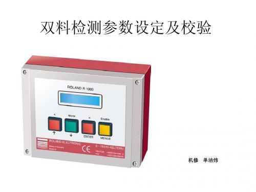
双料检测
- 格式:ppt
- 大小:2.94 MB
- 文档页数:20

对中台双料检测设定摘要:一、引言二、中台双料检测的定义和作用三、中台双料检测的具体流程1.原材料检测2.生产过程检测3.成品检测四、中台双料检测的重要性1.保障产品质量2.提高生产效率3.降低企业风险五、中台双料检测的未来发展趋势1.技术创新2.智能化发展3.行业标准完善正文:一、引言在我国制造业中,中台双料检测作为一种质量控制手段,越来越受到企业的重视。
本文将对中台双料检测进行详细介绍,以帮助大家更好地理解这一检测方式。
二、中台双料检测的定义和作用中台双料检测,是指在生产过程中,对原材料、生产过程和成品进行两次以上的检测。
通过这一检测方式,可以确保产品质量和生产过程的稳定,为企业带来良好的经济效益。
三、中台双料检测的具体流程1.原材料检测原材料检测是确保产品质量的第一道关卡。
企业需要对原材料的性能、成分、规格等进行严格检测,以确保原材料符合生产要求。
2.生产过程检测在生产过程中,企业需要对各个生产环节进行实时监控,确保生产过程符合预定标准。
这一环节的检测,有助于发现生产过程中的问题,并及时进行调整。
3.成品检测成品检测是对产品质量的最后把关。
企业需要对成品进行全面的检测,包括性能、外观、安全性等方面,确保产品合格。
四、中台双料检测的重要性1.保障产品质量通过中台双料检测,企业可以确保产品符合相关质量标准,提高客户满意度,提升企业品牌形象。
2.提高生产效率通过对生产过程的实时监控和调整,企业可以减少生产中的问题,提高生产效率,降低生产成本。
3.降低企业风险中台双料检测有助于企业及时发现潜在的质量问题和安全隐患,从而采取相应措施,降低企业风险。
五、中台双料检测的未来发展趋势1.技术创新随着科技的不断发展,新的检测技术和设备不断涌现,中台双料检测将更加精确、高效。
2.智能化发展在大数据、人工智能等技术的支持下,中台双料检测将实现智能化,为企业提供更精准的决策依据。

罗兰双料检测报警代码摘要:1.罗兰双料检测报警代码概述2.罗兰双料检测报警代码的工作原理3.罗兰双料检测报警代码的应用场景4.罗兰双料检测报警代码的优势与不足5.总结正文:1.罗兰双料检测报警代码概述罗兰双料检测报警代码是一种用于检测设备状态的编码系统,它可以同时检测两个参数,并通过报警代码的方式,将检测结果传递给用户。
这种编码系统广泛应用于各种工业生产场景,如机器制造、化工生产等。
2.罗兰双料检测报警代码的工作原理罗兰双料检测报警代码的工作原理是,首先通过传感器等设备,实时检测生产设备的状态,如温度、压力等。
然后,将检测到的数据进行处理,生成对应的报警代码。
最后,通过报警器等设备,将报警代码传递给用户,以便用户及时了解设备状态,并采取相应的措施。
3.罗兰双料检测报警代码的应用场景罗兰双料检测报警代码在各种工业生产场景中都有广泛的应用。
例如,在机器制造场景中,可以通过罗兰双料检测报警代码,实时监测机器的运行状态,如温度、压力等,一旦检测到异常,就可以及时报警,避免设备损坏。
在化工生产场景中,罗兰双料检测报警代码可以检测设备的泄漏、压力异常等,确保生产过程的安全。
4.罗兰双料检测报警代码的优势与不足罗兰双料检测报警代码的优势在于,可以实时监测设备的状态,及时发现异常,并通过报警代码的方式,将异常信息传递给用户,提高了生产的安全性和效率。
此外,罗兰双料检测报警代码的使用,也降低了人工巡检的工作量。
然而,罗兰双料检测报警代码也存在一些不足。
例如,对于复杂的设备状态,可能需要多个报警代码来进行描述,这会增加用户的理解难度。
此外,罗兰双料检测报警代码的设备和系统,也需要定期进行维护和更新,以保证其正常工作。
5.总结总的来说,罗兰双料检测报警代码是一种重要的工业生产设备监测手段,它可以实时监测设备的状态,并通过报警代码的方式,将异常信息传递给用户,提高了生产的安全性和效率。
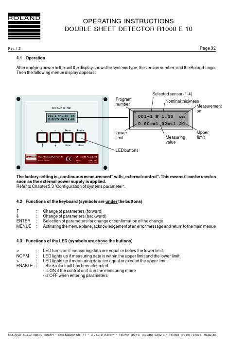
OPERA TING INSTRUCTIONSDOUBLE SHEET DETECTOR R1000 E 10Rev. 1.2ROLAND Page 324.1OperationAfter applying power to the unit the display shows the systems type, the version number, and the Roland-Logo.Then the following menue display appears:The factory setting is …continuous measurement“ with …external control“. This means it can be used as soon as the external power supply is applied.Refer to Chapter 5.3 ”Configuration of systems parameter“.4.2Functions of the keyboard (symbols are under the buttons)↑:Change of parameters (forward)↓:Change of parameters (backward)ENTER:Selection of parameters for change or confirmation of the change MENUE :Activating the menue plane, acknowledgement of an error message and return to the main menue4.3Functions of the LED (symbols are above the buttons)<:LED turns on if measuring data are equal or below the lower limit.NORM:LED lights up if measuring data is within the upper limit and the lower limit.>:LED lights up if measuring data are equal or exceed the upper limit.ENABLE :- Blinks if a fault has been detected- is ON if the control unit is in the measuring mode- is OFF when entering parameters001-1 N=1.00 on0.80<=1.02=>1.20Program number Nominal t hicknessMeasurement on 001-1 N=1.00 on0.80<=1.02=>1.20Measuring value Upper limitLowerlimitLED buttons Selected sensor (1-4)OPERA TING INSTRUCTIONSDOUBLE SHEET DETECTOR R1000 E 10Rev. 1.2ROLAND Page 335.Control unit configuration 5.1 Menue structurw E 10Menue buttonChange of parametersis not possibleLanguage German / English / ItalianP 75P 42P 36Dimensionsmm / inch / %(mm) / % (inch)Measuring modeSingle measurement (external)Continuous measurementControlinternalexternal300 / 600 / 1200 / 2400 /CLR Parameter (Clear Programm Parameter)offonPasswordyesnoOutput 0-1-2 Sheet0 V active24 V active External Adjustment (Teach-In and Zero adjust) possible (not with Version A)yesno)Number of sensors (Version 4P only)1 - 4Sensor selection v ia:Program changeInputs A and BFactory setting: Do not change! Parameter Parameter Back Up(Version C only)Parameter Back Up mode Sensor number 1-4 (at Version 4P) not available (in Standard-Version)Nominal thickness (0,03 - 2,5 mm) at P 36(0,03 - 4,0 mm) at P 42(0,03 - 6,0 mm) at P 75TO% (100-150%) and absolute TU% (0-100%) and absolute Zero adjust off on Teach-In off onOPERA TING INSTRUCTIONSDOUBLE SHEET DETECTOR R1000 E 10Rev. 1.2ROLAND Page 345.2General informationIn order to select and change parameters it is necessary to push the menue button. This activates the menue for keying-in the password.Press the ENTER button in order to activate the password. The first digit blinks and can be changed with the ARROW keys. Confirm the input with ENTER. The next digit blinks to enable and confirm the input of the number.Continue in the same manner to the 4th digit. The next menue appears after the correct password has been entered in. Otherwise the program returns to the first digit and the input must be repeated.The procedure described above:-selection of a parameter with ENTER-changing of a parameter with the up and down arrow keys (↑ higher values, ↓ lower values) and confirmation of the input with ENTER is the same in all menue points.The control unit leaves the menue level by pressing the menue key again.After confirmation of the last parameter point the program returns to the first parameter point.After leaving the menue level the password stays active for about 5 min. If the menue key is pressed during this time, it is possible to return into the menue without entering the password again. This simplifies the selection andconfirmation of the necessary parameters. If the password is not entered, it is possible to review the parameters of the active measuring programs but it is not possible to change the parameters.The program returns automatically into the measuring mode after 5 min without pressing any keys on the menue level (this is the same effect as pressing the menue button).Important:Depending on the version of the control unit some of the following menue points may notbe available. The description points this out.In this menue point the input of either Systems parameters (general adjustments such as language), Program parameters (specific selections such as nominal thickness) and Data backup (Version C only) are determined.The menue level can only be left by pressing the menue button again.After the last parameter item the program jumps automatically to the first item.The password is 4711Password ****configurationProg. ParameterOPERA TING INSTRUCTIONSDOUBLE SHEET DETECTOR R1000 E 10Rev. 1.2ROLAND Page 355.3Configuration of systems parameterNext picture:Selection of the dialogue language.Currently German, English, Italian, French and Spanish are available.Next picture:In this menu the sensor is selected which will be connected to the unit.Available are sensors P 36, P 42 and P 75.Important:If parameter sets have already been stored for any of the sensors, then they are deleted, if a newsensor is selected. The display "Clear parameters" appears.Example:Parameter programs have been stored for the P 42 sensor. Now the P 75 is selected. The existing parameter sets are now deleted because the new sensor has a different linearized curve and the previously stored parameters are not valid for the newly selected sensors.Next picture:This menue tells the unit whether dimensions should be mm, inch, % [mm] or % [inch].Special operating mode …percent“:When selected the dimensions as percent it is possible to choose as approximate value mm (%[mm]) or inch (%[inch]) This feature allows a Teach-In without manually entering actual sheet thickness in mm or inch.In the Teach-In process the sheet in front of the sensor is recorded as 100%. In order to give the operating personnel an indication of thickness the approximate value is displayed in mm or inch as selected in the configuration procedure.Next picture:This menue point allows the selection between "single" or "continuous" measurement.Single measurement:If a signal is put to terminal 5 "measurement start" then the control unit initiates onemeasurement. Each measurement must be started anew.Continuous measurement:As long as a signal is active on terminal 5 the unit measures continuously.The menue point is not accessible in the single measurement mode.config. item 1language: englishconfig. item 2Sensor typ: P42config. item 3unit : mmconfig. item 4mode: singleOPERA TING INSTRUCTIONSDOUBLE SHEET DETECTOR R1000 E 10Rev. 1.2ROLAND Page 36In this menue point the type of control for the continuous measurement mode is configured.Internal:The control unit measures continuously as soon as power in applied.No external signal ”measurement start“ is necessary.This is the standard factory setting.External:The control unit measures continuously as soon as the signal ”measurement start“ is applied toterminal 5.This makes is possible to start the measurement at defined times e.g. as soon as the sensor is reliably placed on the sheet and before the sensor is removed.Version ”C“ only Selection of the baud rate of the RS232 interface. Depending on the connected PLC, baud rates between 300and 19200 can be selected.CLR = clear parameters. It is possible to delete all measuring programs with this function. The valuee for nominal thickness is set automatically to 0.03 mm or 0.001 inch. Default values are as follows:Default values for upper limit in % are 120 % and for lower limit in % are 80 %.At this point the password can be activated or deactivated.Under this item the characteristics of the outputs 0-sheet,1-sheet and 2-sheets are selected:+ 24 V =as shown at the timing diagrams (see chap. 6 following)0 V =the switching level in the timing diagrams at OUT1, OUT2, OUT3 is reversed; this means that theapplicable signals in the timing diagrams are also reversed.Attention:The output ENABLE is not affected.config. item 5control: internalconfig. item 6baud rate: 9600config. item 7CLR Param.: ausconfig. item 8Password: yesconfig. item 9Level 0-1-2: 24 VOPERA TING INSTRUCTIONSDOUBLE SHEET DETECTOR R1000 E 10Rev. 1.2ROLAND Page 37yes:- Teach-In at IN1 is possible. The signal IN1 can be used to execute the Teach-In function.- Zero adjust at IN2 is possible. The signal IN2 can beused to execute the Zero adjust function.no:Teach-In or zero adjust cannot be executed via inputs IN1 or IN2.In this menue the unit version is displayed.This setting is factory adjusted and must not be changed .In this menue point the number of sensors to be connected are entered. A reduction of the number of sensors erases the program parameters of the sensors deleted.In this menue point the sensor switching procedure is configured:Ext.:The switching is accomplished via the external PLC cables Sensor selection A and B (see chap. 7.3)This configuration results in a quicker sensor switching procedure.Prog.:Sensor switching is accomplished via the program selection (see chap. 7.2).A sensor is assigned to each program.The advantage of this configuration is lower programming effort.This menue displays the hardware (HW) and software (SW) versions.config. item 10ext. adj.: noconfig. item 11version: 4P COHW-V.: E10-7SW-Version: 28config. item 13sel. sensor:ext.Unit version 4P onlyconfig. item 12number sensors: 4Unit version 4P onlyOPERA TING INSTRUCTIONSDOUBLE SHEET DETECTOR R1000 E 10Rev. 1.2ROLAND Page 385.4Configuration of program parameterThe program parameters are necessary data for each measuring program.First menue point:This denotes the measuring program for which the parameters are to be selected..Next menue point:Here the measuring sensor can be selected (1, 2, 3 or 4).Next menue point:Here it is possible to enter the nominal thickness.The maximum is described in the sensor diagrams (see chap. 2.6).In the following four menue points the values for the upper limit and the lower limit can be entered either as percentages or in absolute terms. If a measuring value reaches of falls below the lower limit, the ZERO SHEET output is activated. If reaching or exceeding the upper limit, the 2-sheet output is activated. Percentages always refer to the nominal sheet thickness.The absolute limit and the percentage limits are recalculated each time a change is made either as percentage or in absolute terms and vice versa.Next menue point:Here the percent or absolute switching limit for the upper switching threshold is adjusted. Values between 100and 150% are possible. In addition the absolute value of the switching limit is displayed.Here the percent or absolute switching limit for the lower switching threshold is adjusted. Values between 0 and 100% are possible. In addition, the absolute value of the switching limit is displayed.Parameter 1Program No.: 1Parameter 3nominal: 1.00 mm Parameter 4UP: 120% 1.20 mmParameter 5LOW: 80% 0.80 mmThis parameter is not available if teaching dimension is …percent“(Config. item 3: unit)Parameter 2sensor number:1Version 4P only and if Systems parameter 12 is set to…sel. sensor: prog.“Rev. 1.2Page 39Parameter 6Zero adjust: offThis function enables zero adjust in order to compensate for environmental factors of the control unit, cable length and the mounting of the sensor.Important:During zero adjust the sensor must not be covered by sheet metal.The minimum sheet distance has to be 10 mm.Otherwise, the error code "25 zero adjust " is issued.A zero adjust should be activated before each teach in. For exact timing compare diagram (see attachment).Parameter 7Teach-In: offThis menue serves the Teach-In function. After the start of Teach-In the following display appears:Parameter 8TI-value: 0.97 mmThis parameter shows the result of the Teach-In procedure. This value can be accepted or -if necessary -changed in order to calibrate the unit (Change is not possible if teaching dimension is …percent“; config. item 3).Important:The measured value can differ by a maximum of 25% from nominal value. Otherwise the error message 30 …Teach-In error“ appears (This note is not valid if teaching dimensionis …percent“, config. item 3).If the Teach-In signal is issued externally via the parallel or the RS 232 interface then the control unit transforms the measured Teach-In value into the nominal value. (This note is not valid if teaching dimension is …percent“, config. item 3).See attachment …Teach-In“ for the appropriate timing diagram.5.5Parameter backup (Version C only)Data back upactiveThe special Roland Electronic software RPP (Operating system DOS) enable the user, via the RS 232 interface to make back up copies of the systems configuration and the parameters. If the control unit faults out the parameters can be down loaded to a spare parts control unit.Rev. 1.2Page 253.9Wiring diagram PLC-cable, sensor cable and power supply(Version B, Opto coupler outputs)Complete wiring is necessary only if all options are to be used.The description within the grey areas is relevant for version 4P only.seeattachment。
双料检测传感器的原理
双料检测传感器是一种能在生产过程中,将物料的重量信息转换为电信号输出的传感器。
这种传感器的结构特点是:在双料检测传感器内设有两个金属电极,一个检测料斗中物料的重量,另一个检测料斗中物料的速度。
当两个电极之间产生的电位差大于一定数值时,输出信号为高电平;反之,当两个电极之间产生的电位差小于一定数值时,输出信号为低电平。
两个金属电极之间的距离d等于两个传感器之间的距离d。
该传感器主要用于计量系统中各种物料的重量、速度和流量。
可用于各种给料装置中进行给料控制。
双料检测传感器按其检测原理可分为电容式、磁致伸缩式和电磁感应式三种。
按其结构又可分为插装式、插拔式和固定式三种。
双料检测传感器是一种在连续生产线上使用的物料重量和速度的测量仪表,主要用于计量系统中各种物料的重量、速度和流量,能自动完成给料、计量、称重、报警等多种功能,而且具有体积小、重量轻、无电磁干扰、精度高、性能稳定等特点。
—— 1 —1 —。
对中台双料检测设定【原创实用版】目录1.对中台双料检测设定的概述2.中台双料检测设定的必要性3.中台双料检测设定的具体实施步骤4.中台双料检测设定的优势和可能的问题5.结论正文一、对中台双料检测设定的概述中台双料检测设定是一种用于检测产品品质的方法,它通过同时对产品进行两次检测,以确保产品的质量符合标准。
这种方法不仅可以提高检测的准确性,还可以有效地避免因单一检测导致的误判。
二、中台双料检测设定的必要性在产品生产过程中,品质检测是至关重要的环节。
然而,单一的检测方式往往存在一定的误差,可能会导致一些不合格的产品被误判为合格,从而流入市场。
中台双料检测设定正是为了解决这个问题,通过两次检测,可以有效地减少误判的可能性,提高产品的品质。
三、中台双料检测设定的具体实施步骤中台双料检测设定的具体实施步骤可以分为以下几个步骤:1.首先,确定需要检测的产品和检测标准。
2.然后,选择合适的检测方法和设备,对产品进行第一次检测。
3.在第一次检测完成后,对检测结果进行分析,如果合格,则进行第二次检测;如果不合格,则可以进行修复或重新生产。
4.第二次检测完成后,再次对检测结果进行分析,如果两次检测结果一致,则可以确定产品合格;如果结果不一致,则需要重新检测或请教专家。
四、中台双料检测设定的优势和可能的问题中台双料检测设定的优势主要表现在以下几个方面:1.可以有效地提高检测的准确性,减少误判的可能性。
2.可以提高产品的品质,提升客户满意度。
3.可以有效地避免因单一检测导致的误判,从而降低生产成本。
然而,中台双料检测设定也可能存在一些问题,例如,两次检测的设备和方法可能存在差异,导致检测结果不一致;此外,中台双料检测设定需要投入更多的人力和物力,可能会增加生产成本。
五、结论总的来说,中台双料检测设定是一种有效的产品品质检测方法,它可以提高检测的准确性,提高产品的品质,提升客户满意度。