薄膜电容器规格书
- 格式:doc
- 大小:250.50 KB
- 文档页数:4
美的制冷家用空调国内事业部电子元器件规格书供方名称:厦门法拉电子股份有限公司器件名称:薄膜电容型号规格:参见第六项表格物料编码:参见第六项表格厂家型号:MKP62-275VAC-104TSSKP15MKP62-275VAC-274TSSMP22.5MKP62-275VAC-105TSSMP22.5MKP62-275VAC-224KP15MKP62-275VAC-474MP22.5MKP62-275VAC-105MP22.5MKP62-275VAC-335KP27.5MKP62-275VAC-155MP22.5编制:审核:供方会签:日期:版本:V1.0注意事项:1、本规格书双方签字后正式生效,本规格书连封面合共6页;2、本规格书一式两份,版本由使用方与供方共同维护;任何对内容的改动必须经双方同意,并以书面文件的形式发布。
规格书更新纪录:一厂家品牌中英文:厦门法拉电子股份有限公司(鹭岛牌)Xiamen Faratronic Co.,Ltd.,()二产地(国内的写工厂地址):中国厦门市金桥路101号三厂家型号及型号含义:F15B3.7 :F15表示电容器引线成型(弯脚)15mm,B3.7表示电容器引线成型(弯脚)15mm后,剪短引线长度为3.7mm。
3. 引线形状及间距图:Note: W±0.4 H±0.4 T±0.4五安全认证说明:●六 外观尺寸及关键参数对照表:P=7.5 or 10.0mm P ≥15.0mm and C R ≤1.0μF符号说明Marking Introduction :七、内部结构图:九关键电性能参数及可靠性能:1、全系列产品全部符合ROHS要求2、短路充放电实验方法:给安规电容器两端施加220V AC,0.5S通/0.5S断,1000次。
技术要求:容量变化不超过±20%,损耗角正切值变化量≤0.0015,绝缘电阻仍符合规格书所规定的3、损耗角正切4、耐电压、绝缘电阻5、电性能特性图表(在这里粘贴温度特性、)6、其余测试项目参考美的企业标准《QMN-J52.056-2005安规电容.doc》要求十、厂家关键控制要点1、所有薄膜来料必须经过检验合格后入仓,分切后薄膜必须真空包装放置在温度小于25度,湿度小于60%的环境下贮存,并在进行规范管理。
薄膜电容器的使用要求和电性能参数电磁加热设备把工频的交流电或纯直流电 , 通过半桥 /全桥逆变技术 , 变为高频交流电 (1KHz— 1MHz. 高频交流电通过各种电感性负载后会产生高频交变磁场 . 当金属物体处于高频交变磁场中 , 金属分子会产生无数小涡流 . 涡流使金属分子高速无规则运动 , 金属分子间互相碰撞、磨擦而产生热能 , 最终达到把电能转换为热能的目的 . 电磁加热设备在我们的工作和生活中大量的频繁的使用 . 例如电磁炉 /电磁茶炉 , 电磁炉 , 高频淬火机 , 封口机 , 工业熔炼炉等等 . 本文以三相大功率电磁灶为例 , 浅析薄膜电容器在电磁加热设备中的应用 .一电磁灶三相全桥电路拓扑图二 C1— C6功能说明C1/C2:三相交流输入滤波、纹波吸收 , 提高设备抗电网干扰的能力C1,C2和三相共模电感组成 Pi 型滤波 , 在设备中起电磁干扰抑制和吸收的作用 . 该电路一方面抑制 IGBT 由于高速开关而产生的电磁干扰通过电源线传送到三相工频电网中 , 影响其他并网设备的正常使用 . 另一方面防止同一电网中其他设备产生的电磁干扰信号通过电源线传送到三相工频电网中 , 影响电磁加热设备自身的正常使用 .(对内抑制自身产生的干扰 , 对外抵抗其他设备产生的干扰 , 具有双面性EMC=EMI+EMS在实际使用中 ,C1可以选择 MKP-X2型 (抑制电磁干扰用固定电容器 , 容量范围在 3µF-10µF之间 , 额定电压为 275V.AC -300V.AC. 采用 Y 型接法 , 公共端悬空不接地 . C2可以选择 MKP 型金属化薄膜电容器 , 容量范围在 3µF-10µF之间 , 额定电压为 450V.AC -500V.AC ,采用三角形接法 .新晨阳C1和 C2原则上选用的电容量越大 , 那么对于电磁干扰的抑制和吸收效果越好 . 但是电容量越大 , 那么设备待机时的无功电流就越大 . 耐压方面要根据设备使用地域的电网情况而合理保留一定的余量 , 防止夜间用电量非常小的时候 , 电网电压过高而导致电容器电压击穿或寿命受到一定的影响 .C3: 整流后平滑滤波、直流支撑 (DC-Link,吸收纹波和完成交流分量的回路。
3000v高压薄膜电容22nf下载温馨提示:该文档是我店铺精心编制而成,希望大家下载以后,能够帮助大家解决实际的问题。
此文下载后可定制随意修改,请根据实际需要进行相应的调整和使用。
并且,本店铺为大家提供各种各样类型的实用资料,如教育随笔、日记赏析、句子摘抄、古诗大全、经典美文、话题作文、工作总结、词语解析、文案摘录、其他资料等等,如想了解不同资料格式和写法,敬请关注!Downloaded tips: This document is carefully compiled by the editor. I hope that after you download them, they can help you solve practical problems. The documents can be customized and modified after downloading, please adjust and use it according to actual needs, thank you!In addition, our shop provides you with various types of practical materials, such as educational essays, diary appreciation, sentence excerpts, ancient poems, classic articles, topic composition, work summary, word parsing, copy excerpts, other materials and so on, want to know different data formats and writing methods, please pay attention!3000V高压薄膜电容22nF的详细演示。
薄膜电容产品手册解释说明以及概述1. 引言1.1 概述本手册旨在提供关于薄膜电容产品的详尽信息和指南。
作为一种重要的电子元件,薄膜电容产品在各个领域都有广泛的应用。
了解其基本原理、分类特点以及制造工艺等关键内容,对于正确选择和使用薄膜电容产品至关重要。
1.2 文章结构本文主要分为五个部分。
引言部分将介绍文章的目的和结构,以便读者能够更好地理解全文内容。
正文部分将深入探讨薄膜电容产品的基本原理、分类与特点以及应用领域。
接下来,详细解释与说明部分将涵盖制造工艺与材料选择、性能指标解读与测试方法,以及使用注意事项及故障排除方法。
手册编写与更新维护流程将在第四部分进行介绍,包括手册撰写流程、更新维护流程以及发布与分发方式的选择。
最后,在结论与总结部分将再次强调薄膜电容产品手册的重要性。
1.3 目的编写这本“薄膜电容产品手册”的目的是为了提供一个详细且实用的参考指南,帮助读者更好地了解薄膜电容产品的特性、应用和使用。
通过阅读本手册,读者将能够更有效地选择适合自己需求的薄膜电容产品,并掌握正确的使用方法和故障排除技巧。
此外,本手册还将介绍撰写和更新维护手册的流程,以确保手册内容始终保持最新和准确。
请根据上述内容撰写“1. 引言”部分的文字。
2. 正文:2.1 薄膜电容产品的基本原理:薄膜电容产品是一种利用薄膜材料作为介电体的电容器。
它包括两个主要部分:电极和介电层。
通常,金属或导电聚合物被应用于作为电极,而介电层则由薄膜材料构成。
通过在不同的表面施加正负电荷来改变两个电极之间的感应电压,从而实现对信号的传递和存储。
此外,由于薄膜材料具有很高的绝缘性能,使得这种类型的电容器具有较低的漏失率和较高的绝缘强度。
2.2 薄膜电容产品的分类与特点:根据使用材料以及制造工艺不同,薄膜电容产品可以分为多个类别。
其中常见的包括铝箔式、聚酯式、聚酰亚胺式等。
每种类型都有其特定的特点和优势。
例如,铝箔式具有较高的频率响应和较低噪音级别;聚酯式则具有良好的耐温性能和长寿命;聚酰亚胺式则具有较高的温度稳定性和抗振动能力。
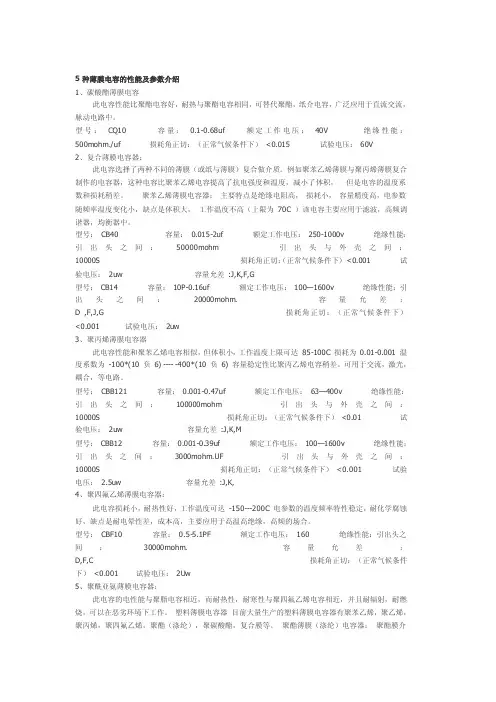
5种薄膜电容的性能及参数介绍1、碳酸酯薄膜电容此电容性能比聚酯电容好,耐热与聚酯电容相同,可替代聚酯,纸介电容,广泛应用于直流交流,脉动电路中。
型号:CQ10 容量:0.1-0.68uf 额定工作电压:40V 绝缘性能:500mohm./uf 损耗角正切:(正常气候条件下)<0.015 试验电压: 60V2、复合薄膜电容器:此电容选择了两种不同的薄膜(或纸与薄膜)复合做介质。
例如聚苯乙烯薄膜与聚丙烯薄膜复合制作的电容器,这种电容比聚苯乙烯电容提高了抗电强度和温度,减小了体积,但是电容的温度系数和损耗稍差。
聚苯乙烯薄膜电容器:主要特点是绝缘电阻高,损耗小,容量精度高,电参数随频率温度变化小,缺点是体积大,工作温度不高(上限为70C )该电容主要应用于滤波,高频调谐器,均衡器中。
型号:CB40 容量:0.015-2uf 额定工作电压: 250-1000v 绝缘性能:引出头之间:50000mohm 引出头与外壳之间:10000S 损耗角正切:(正常气候条件下)<0.001 试验电压:2uw 容量允差:J,K,F,G型号:CB14 容量:10P-0.16uf 额定工作电压: 100—1600v 绝缘性能:引出头之间:20000mohm. 容量允差:D ,F,J,G 损耗角正切:(正常气候条件下)<0.001 试验电压:2uw3、聚丙烯薄膜电容器此电容性能和聚苯乙烯电容相似,但体积小,工作温度上限可达85-100C 损耗为 0.01-0.001 温度系数为-100*(10 负6) ---- -400*(10 负6) 容量稳定性比聚丙乙烯电容稍差。
可用于交流,激光,耦合,等电路。
型号:CBB121 容量: 0.001-0.47uf 额定工作电压:63—400v 绝缘性能:引出头之间:100000mohm 引出头与外壳之间:10000S 损耗角正切:(正常气候条件下)<0.01 试验电压:2uw 容量允差:J,K,M型号:CBB12 容量:0.001-0.39uf 额定工作电压:100—1600v 绝缘性能:引出头之间:3000mohm.UF 引出头与外壳之间:10000S 损耗角正切:(正常气候条件下)<0.001 试验电压: 2.5uw 容量允差:J,K,4、聚四氟乙烯薄膜电容器:此电容损耗小,耐热性好,工作温度可达-150---200C 电参数的温度频率特性稳定,耐化学腐蚀好,缺点是耐电晕性差,成本高,主要应用于高温高绝缘,高频的场合。
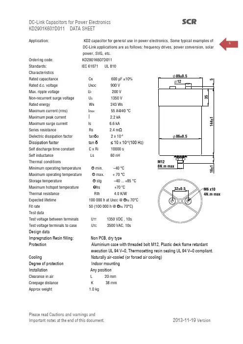
1Application: KD2 capacitor for general use in power electronics, Some typical examples ofDC-Link applications are as follows: frequency drives, power conversion, solar power, SVG, etc.Ordering code: KD2901K607D011 Standards: IEC 61071 UL 810 CharacteristicsRated capacitance C N 600 μF ±10% Rated d.c. voltage U NDC 900 V Max. ripple voltage U r 200 V Non-recurrent surge voltage U s 1350 V Rated energy W N 243 Ws Maximum current (rms) I max 55 A@40 °C Maximum peak current Î 2.2 kAMaximum surge current Is 6.6 kA Series resistance Rs 2.4 m Ω Dielectric dissipation factor tan δo 2 x 10⁻⁴Dissipation factor tan δ ≤ 10 x 10-4(100 Hz)Self discharge time constant C x Ri 10000 s Self inductance Ls 60 nH Thermal conditionsMinimum operating temperature Θmin. –40 °C Maximum operating temperature Θmax. + 70 °C Storage temperature Θstg –40 ... +85 °C Maximum hotspot temperature Θhs +70 ºC Thermal resistance Rth 4.0 K/W Expected lifetime 100 000 h at U NDC @ Θhs 70°C Fit rate 50 (100 000 h @ Θhs 70°C) Test dataTest voltage between terminals U TT 1350 VDC , 10s Test voltage terminals to case U TC 3500 VAC, 10sDesign dataImpregnation Resin filling: Non PCB, dry typeProtection Aluminium case with threaded bolt M12, Plastic deck flame retardantexecution UL 94 V –0, Thermosetting resin sealing UL 94 V –0 compliant.Cooling Naturally air-cooled (or forced air cooling) Degree of protection Indoor mounting Installation Any positionClearance in air L 20 mm Creepage distance K 38 mm Approx weight 1.0 kg2Lifetime statements vs. Failure rateIn the lifetime expectancy graphic, statements for more than 200,000 hrs are cut off as they are technically unreasonable. For higher hotspot temperatures, no statements are made regarding operation at overvoltage: the simultaneous operation at limit values results in unpredictable conditions. Here, the statement of a FIT rate - that reflects the growing risk at such extreme conditions - would be of far better use. Lifetime Expectancy GraphsFIT rates (Failures In Time):By reflecting the probability (in other words: risk) of failures during the operating period under selected operating conditions, it provides information on what effects to expect when de-rating (or over-loading) a capacitor. The failure probability of a component is a statistical value which is described by a log-normal distribution:N = N o × e ¯λtN = number of functional components after period t N o = total number of components at time t = 0 λ = failure rateλ is the failure rate, which alternatively is also stated as the so-called FIT-rate (FIT = Failures In Time = λ×109). Service cycles may be calculated based on the so-called MTBF value (mean time between failures): MTBF = 1/λ. The failure rate is very closely linked with the operating temperature and the operating voltage applied to the capacitor. As standard, our FIT rates are related to a realistic (from a technical and statistical point of view) operating interval of t=100,000 hours, assuming a capacitor hotspot temperature of 70°C. Hotspot is the only reliable criterion in relation to the capacitor’s temperature stress. The outside temperatures may be comparably low, however with high electrical stress the temperature rise in the capacitor may be substantial due to the power dissipation losses produced inside. This could result in the same temperature stress as a generally high ambient temperature.3The simultaneous operation of capacitors at highest permissible voltage and operating temperature should be avoided; otherwise, failure rates may increase beyond reasonable technical reliability.In fact, a FIT rate of 50 would mean, for example: “If 10,000 capacitors are operated simultaneously for 100,000 hours at rated voltage and with a hotspot temperature of no more than 70°C, then out of this batch no more than 50 pcs may fail during the entire period.” Any period during which the hotspot temperature is lower than 70°C, or the voltage is less than rated voltage, will contribute to a reduction of the 50 FIT. After the reference interval, the capacitors will continue operating; however the probability of failures may change. It shall be noted that the statements on FIT rates are based mainly on long-year empirical experience; at SCR, we are conducting numerous and regular reliability tests to verify and back up our empiricalknowledge. However dedicated studies designed to prove FIT rates would require the test of thousands of capacitors, over hundreds of thousands of hours, which is technically and commercially impossible. Even the use of statistical methods and accelerated ageing factors encounters physical and chemical limits. Hence lifetime formulas such asLifetime (U) = L N x (U rated /U working )8and Lifetime (Θ) = L N x 2(Θrated-Θworking)/7should not be used to calculate absolute figures of expected lifetime. These rules and formulas are mainly designed to give an approximate feeling for the importance of voltage and temperature.All standard items of SCR are designed and dimensioned to comply with their FIT rate as stated in the catalogue or special data sheet. FIT rate statements related to longer reference intervals can be made on request. Further, capacitor designs can be adapted on request to achieve lower FIT at the intended operating conditions.Based on our current state of knowledge derived from test data and experience, we quote the following FIT rates for our standard products at the a.m. conditions: KD series Failure Quota Graphs4Rated capacitance C NCapacitance value rated at 20°C / 50 Hz. Rated AC voltage U NMaximum operating peak recurrent voltage of either polarity of a reversing type waveform for which the capacitor has been designed. Rated DC voltage U NDCMaximum operating peak voltage of either polarity but of a non-reversing type waveform,for which the capacitor has been designed,for continuous operation. Ripple voltage U rMaximum value of the peak-to-peak alternating component of the unidirectional voltage. This value is stated only for DC-capacitors. The peak-to-peak value of AC- and AC/DC-types is always 2 × U NAC . Non-recurrent surge voltage U sPeak voltage induced by a switching or any other disturbance of the system which is allowed for a limited number of times and duration.- Maximum duration: 50 ms / pulse. Maximum number of occurrences: 1000 (during load) Insulation voltage U iRms rated value of the insulation voltage of capacitive elements and terminals to case or earth. rms voltage UrmsRoot mean square of max. permissible value of sinusoidal AC voltage in continuous operation. In power electronics, the RMS voltage is usually not the rated voltage value of the capacitor. Maximum current I maxMaximum rms current for continuous operation. Maximum rate of voltage rise (du/dt)maxMaximum permissible repetitive rate of voltage rise of the operational voltage. Maximum peak current ÎMaximum permissible repetitive current amplitude during continuous operation.Maximum peak current (Î) and maximum rate of voltage rise (du/dt)max on a capacitor are related as follows:Î = C × (du/dt)maxMaximum non-repetitive rate of voltage rise (du/dt)SPeak rate of voltage rise that may occur non-repetitively and briefly in the event of a fault. Maximum surge current Î sAdmissible peak current induced by a switching or any other disturbance of the system which is allowed for a limited number of times (1000 times) and duration (50 ms / pulse).Îs = C × (du/dt)sAmbient temperature ΘATemperature of the surrounding air, measured at 10 cm distance and 2/3 of the case height of the capacitor. Lowest operating temperature ΘminLowest permitted ambient temperature at which a capacitor may be energized. Maximum operating temperature ΘmaxHighest permitted capacitor temperature during operation, i.e. temperature at the hottest point of the case. It is, however, not sufficient to monitor the surface temperature. Life-span and safe operation crucially depend on the observance of the hotspot temperature.5Hot-spot temperature ΘhsTemperature zone inside of the capacitor at hottest spot. It has to be noted that,depending on the thermal power dissipation generated inside the capacitor,there is always a temperature difference between hotspot and surface. As the hotspot is usually not accessible for measurement, Θhs must be calculated based on the data stated in the catalogue or data sheet:Θhs =ΘA + Irms 2x ESR x R thImportant: No thermal dissipation losses are admissible when operating a capacitor at an ambienttemperature equal to the upper category temperature,i.e. Irms and Q shall be zero (operation at pure DC voltage) !Dielectric dissipation factor tan δ0Constant dissipation factor of the dielectric material for all capacitors at their rated frequency.The typical loss factor of pp film is tan δ0 = 2 x 10⁻⁴. Dissipation factor tan δLoss factor of the capacitor at sinusoidal ac voltage and applied frequency.It is calculated as follows:tan δ (ƒ) = tan δ0 + R S x 2πƒ x C N Series resistance R sThe sum of all Ohmic resistances occurring inside the capacitor. Equivalent Series Resistance ESRRepresents the sum of all loss resistances occurring in the capacitor. It depends on frequency and is essential for the calculation of the capacitor’s total power losses.ESR = R S +tan δ0 /(2πƒ x C N ) Thermal resistance R thThe thermal resistance indicates by how many degrees the capacitor temperature at the hot spot rises in relation to the dissipation losses. Maximum power loss P maxMaximum permissible power dissipation for the capacitor’s operation.P max =(Θhs – ΘA )/R th Self inductance LsThe sum of all inductive elements which are contained in a capacitor. Resonance frequency frThe lowest frequency at which the impedance of the capacitor becomes minimum.fr = 1/(2π Ls x C N ) Rated energy contents W NEnergy stored in the capacitor when charged at rated voltage.W N =1/2C N × U N ² Clearance in air LThe shortest distance between conducting parts of the terminals or between terminals and case. In this catalogue, we state only the shorter. Creepage distance KThe shortest distance along an insulated surface between conducting parts of the terminals or between terminals and case. In this catalogue, again we state only the shorter.6Cautions and warnings_ In case of dents of more than 1 mm depth or any other mechanical damage, capacitors must not be used at all._ Check tightness of the connections/terminals periodically._ The energy stored in capacitors may be lethal. To prevent any chance of shock, discharge and short-circuit the capacitor before handling._ Failure to follow cautions may result, worst case, in premature failures, bursting and fire._ SCR is not responsible for any kind of possible damages to persons or things due to improper installation and application of capacitors for power electronics. Safety_ Electrical or mechanical misapplication of capacitors may be hazardous. Personal injury or property damage may result from bursting of the capacitor or from expulsion of oil or melted material due to mechanical disruption of the capacitor._ Ensure good, effective grounding for capacitor enclosures._ Observe appropriate safety precautions during operation (self-recharging phenomena and the high energy contained in capacitors)._ Handle capacitors carefully, because they may still be charged even after disconnection._ The terminals of capacitors, connected bus bars and cables as well as other devices may also be energized. _ Follow good engineering practice. Thermal loadAfter installation of the capacitor it is necessary to verify that maximum hot-spot temperature is not exceeded at extreme service conditions. Mechanical protectionThe capacitor has to be installed in a way that mechanical damages and dents in the aluminum can are avoided.Storage and operating conditionsDo not use or store capacitors in corrosive atmosphere, especially where chloride gas, sulfide gas, acid, alkali, salt or the like are present. In dusty environments regular maintenance and cleaning especially of the terminals is required to avoid conductive path between phases and/or phases and ground.The maximum storage temperature is 85 °C. Service life expectancyElectrical components do not have an unlimited service life expectancy; this applies to self-healing capacitors, too. The maximum service life expectancy may vary depending on the application the capacitor is used in.7The following applies to all products named in this publication:1. Some parts of this publication contain statements about the suitability of our products for certain areas of application. These statements are based on our knowledge of typical requirements that are often placed on our products in the areas of application concerned. We nevertheless expressly point out that such statements cannot be regarded as binding statements about the suitability of our products for a particular customerapplication. As a rule, SCR is either unfamiliar with individual customer applications or less familiar with them than the customers themselves. For these reasons, it is always ultimately incumbent on the customer to check and decide whether an SCR product with the properties described in the product specification is suitable for use in a particular customer application.2. We also point out that in individual cases, a malfunction of passive electronic components or failure before the end of their usual service life cannot be completely ruled out in the current state of the art, even if they are operated as specified. In customer applications requiring a very high level of operational safety and especially in customer applications in which the malfunction or failure of a passive electronic component could endanger human life or health (e.g. in accident prevention or life-saving systems), it must therefore beensured by means of suitable design of the customer application or other action taken by the customer (e.g. installation of protective circuitry or redundancy) that no injury or damage is sustained by third parties in the event of malfunction or failure of a passive electronic component.3. The warnings, cautions and product-specific notes must be observed.4. In order to satisfy certain technical requirements, some of the products described in this publication may contain substances subject to restrictions in certain jurisdictions (e.g. because they are classed as“hazardous”). Useful information on this will be found in our Material Data Sheets on the Internet. Should you have any more detailed questions, please contact our sales offices.5. We constantly strive to improve our products. Consequently, the products described in this publication may change from time to time. The same is true of the corresponding product specifications. Please check therefore to what extent product descriptions and specifications contained in this publication are still applicable before or when you place an order. We also reserve the right to discontinue production and delivery of products. Consequently, we cannot guarantee that all products named in this publication will always be available.。
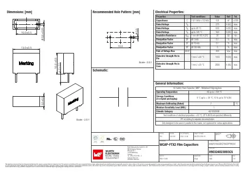
Dimensions: [mm]MX2P010682K275ACPP55004890324023003CSMX2P010682K275ACPP55004 890324023003CSMX2P010682K275ACPP55004 890324023003CSMX2P010682K275ACPP55004 890324023003CSMX2P010682K275ACPP55004 890324023003CST e m p e r a t u r eT T T MX2P010682K275ACPP55004890324023003CSCautions and Warnings:The following conditions apply to all goods within the product series of Film Capacitors of Würth Elektronik eiSos GmbH & Co. KG:General:•This electronic component is designed and manufactured for use in general electronic equipment.•Würth Elektronik must be asked for a written approval (following the certain PPAP level procedure) before incorporating the components into any equipment in the field such as military, aerospace, aviation, nuclear control, submarine, transportation (automotive control, train control, ship control), transportation signal, disaster prevention, medical, public information network etc. where higher safety and reliability are especially required and/or if there is the possibility of direct damage or human injury.•Electronic components that will be used in safety-critical or high-reliability applications, should be pre-evaluated by the customer. •Direct mechanical impact to the product shall be prevented as material of the body, pins or termination could flake or in the worst case it could break.•Avoid any water or heavy dust on capacitors surface, which may cause electrical leakage, damage, overheating or corrosion.•Würth Elektronik products are qualified according to international standards, which are listed in each product reliability report. Würth Elektronik does not warrant any customer qualified product characteristic, beyond Würth Elektronik specifications, for its validity and sustainability over time.•The customer is responsible for the functionality of his or her own products. All technical specifications for standard products also apply to customer specific products.•The component is designed and manufactured to be used within the datasheet specified values. If the usage and operation conditions specified in the datasheet are not met, the body, pins or termination may be damaged or dissolved.•Do not apply any kind of flexural or compressive force onto soldered or unsoldered component.•The capacitance tolerance as specified within the datasheet is only valid on the date of delivery and according specified measurement criteria.Product specificStorage conditions• A storage of Würth Elektronik products for longer than 12 months is not recommended. Within other effects, the terminals may suffer degradation, resulting in bad solderability. Therefore, all products shall be used within the period of 12 months based on the day of shipment.•Do not expose the components into direct sunlight.•The storage condition in the original packaging is defined according to DIN EN 61760-2.•The environment in which the capacitors are operated and stored has to have atmospheric characteristics and must be free of dew condensation and toxic gases (e.g. chlorine, ammonia, sulfur, hydrogen sulphide and hydrogen sulfate).•Do not expose the capacitor to environments with hazardous gas, ozone, ultraviolet rays or any kind of radiation. Avoid any contact of the capacitor with direct sunshine, saltwater, spray of water or types of oil during storage. •The storage conditions stated in the original packaging apply to the storage time and not to the transportation time of the components. Operating climatic conditions•Do not exceed the lower nor the upper specified temperature under no circumstances.•Do not use the capacitors under high humidity, high temperature or under high or low atmospheric pressure which may affect capacitors reliability.•Surface temperature including self-heating must be kept below the maximum operating temperature.Operating load conditions•Due to self-heating the reliability of the capacitor may be reduced, if high frequency AC or pulse is applied.•Consider carefully possible specific changes of electrical characteristics like capacitance over temperature, voltage and time as well as the specific performance over frequency for the actual use conditions.•Avoid any overvoltage and do not apply a continuous overvoltage. If an overvoltage is applied to the capacitor, the leakage current can increase drastically. The applied working voltage is not allowed to exceed the rated working voltage of the specific capacitor.•If film capacitors with safety approvals are operated with a DC voltage exceeding the specified AC voltage, the approvals given on the basis of IEC 60384-14 are no longer valid.Packaging:•The packaging specifications apply only to purchase orders comprising whole packaging units. If the ordered quantity exceeds or is lower than the specified packaging unit, packaging in accordance with the packaging specifications cannot be ensured. Soldering•The solder profile must comply with the Würth Elektronik technical soldering specification. All other profiles will void the warranty. •All other soldering methods are at the customer’s own risk.•Strong forces which may affect the coplanarity of the component’s electrical connection with the PCB (i.e. pins), can damage the part, resulting in void of the warranty.•Customer needs to ensure that the applied solder paste, the paste thickness and solder conditions are enough to guarantee a sufficient solder result according to the relevant criteria of IPC-A-610.•Excessive amount of solder may lead to higher tensile force and chip cracking. Insufficient amount of solder may detach the capacitor due to defective contacts.•Do not use excessive nor insufficient flux.Cleaning•Do not use any other cleaning solvents for box-typed capacitors except: ethanol, isopropanol, n-propanol - water mixtures. After cleaning a drying process with temperatures not exceeding 65°C and not longer than 4 hours is mandatory to prevent any kind ofelectrical damage.Würth Elektronik eiSos GmbH & Co. KGEMC & Inductive SolutionsMax-Eyth-Str. 174638 WaldenburgGermanyCHECKED REVISION DATE (YYYY-MM-DD)GENERAL TOLERANCE PROJECTIONMETHODFPu003.0002022-10-08DIN ISO 2768-1mDESCRIPTION TECHNICAL REFERENCEWCAP-FTX2 Film Capacitors MX2P010682K275ACPP55004ORDER CODE890324023003CSSIZE/TYPE BUSINESS UNIT STATUS PAGECoating, molding and potting of the PCB•If the product is potted in the costumer’s application, the potting material might shrink or expand during and after hardening. Shrinking could lead to an incomplete seal, allowing contaminants into the body and termination. Expansion could damage the body or termination. We recommend a manual inspection after potting to avoid these effects.•If final assemblies will be placed completely in any plastic resin, physical, chemical and thermal influences must be considered. •When coating and molding the PCB, verify the quality influence on the capacitor.•Verify the curing temperature and assure that there is no harmful decomposing or reaction gas emission during curing. •Do not exceed the specified max. self-heating.Vibration resistance•Do not exceed the vibration limits given by IEC60068-2-6.Handling•After soldering, please pay attention not to bend, twist or distort the PCB in handling and storage. •Avoid excessive pressure during the functional check of the PCB. •Avoid bending stress while breaking the PCB.•WCAP-FTXX and WCAP-FTX2 capacitors are not designed and not recommended to be used in series connection to the mains. •The temperature rise of the component must be taken into consideration. The operating temperature is comprised of ambient temperature and temperature rise of the component.The operating temperature of the component shall not exceed the maximum temperature specified.Flammability•Avoid any external energy or open fire (passive flammability).These cautions and warnings comply with the state of the scientific and technical knowledge and are believed to be accurate and reliable.However, no responsibility is assumed for inaccuracies or incompleteness.(V2.2)Würth Elektronik eiSos GmbH & Co. KG EMC & Inductive Solutions Max-Eyth-Str. 174638 Waldenburg GermanyCHECKED REVISION DATE (YYYY-MM-DD)GENERAL TOLERANCEPROJECTION METHODFPu003.0002022-10-08DIN ISO 2768-1mDESCRIPTIONTECHNICAL REFERENCEWCAP-FTX2 Film CapacitorsMX2P010682K275ACPP55004ORDER CODE890324023003CSSIZE/TYPEBUSINESS UNITSTATUSPAGEImportant NotesThe following conditions apply to all goods within the product range of Würth Elektronik eiSos GmbH & Co. KG:1. General Customer ResponsibilitySome goods within the product range of Würth Elektronik eiSos GmbH & Co. KG contain statements regarding general suitability for certain application areas. These statements about suitability are based on our knowledge and experience of typical requirements concerning the areas, serve as general guidance and cannot be estimated as binding statements about the suitability for a customer application. The responsibility for the applicability and use in a particular customer design is always solely within the authority of the customer. Due to this fact it is up to the customer to evaluate, where appropriate to investigate and decide whether the device with the specific product characteristics described in the product specification is valid and suitable for the respective customer application or not.2. Customer Responsibility related to Specific, in particular Safety-Relevant ApplicationsIt has to be clearly pointed out that the possibility of a malfunction of electronic components or failure before the end of the usual lifetime cannot be completely eliminated in the current state of the art, even if the products are operated within the range of the specifications.In certain customer applications requiring a very high level of safety and especially in customer applications in which the malfunction or failure of an electronic component could endanger human life or health it must be ensured by most advanced technological aid of suitable design of the customer application that no injury or damage is caused to third parties in the event of malfunction or failure of an electronic component. Therefore, customer is cautioned to verify that data sheets are current before placing orders. The current data sheets can be downloaded at .3. Best Care and AttentionAny product-specific notes, cautions and warnings must be strictly observed. Any disregard will result in the loss of warranty.4. Customer Support for Product SpecificationsSome products within the product range may contain substances which are subject to restrictions in certain jurisdictions in order to serve specific technical requirements. Necessary information is available on request. In this case the field sales engineer or the internal sales person in charge should be contacted who will be happy to support in this matter.5. Product R&DDue to constant product improvement product specifications may change from time to time. As a standard reporting procedure of the Product Change Notification (PCN) according to the JEDEC-Standard inform about minor and major changes. In case of further queries regarding the PCN, the field sales engineer or the internal sales person in charge should be contacted. The basic responsibility of the customer as per Section 1 and 2 remains unaffected.6. Product Life CycleDue to technical progress and economical evaluation we also reserve the right to discontinue production and delivery of products. As a standard reporting procedure of the Product Termination Notification (PTN) according to the JEDEC-Standard we will inform at an early stage about inevitable product discontinuance. According to this we cannot guarantee that all products within our product range will always be available. Therefore it needs to be verified with the field sales engineer or the internal sales person in charge about the current product availability expectancy before or when the product for application design-in disposal is considered. The approach named above does not apply in the case of individual agreements deviating from the foregoing for customer-specific products.7. Property RightsAll the rights for contractual products produced by Würth Elektronik eiSos GmbH & Co. KG on the basis of ideas, development contracts as well as models or templates that are subject to copyright, patent or commercial protection supplied to the customer will remain with Würth Elektronik eiSos GmbH & Co. KG. Würth Elektronik eiSos GmbH & Co. KG does not warrant or represent that any license, either expressed or implied, is granted under any patent right, copyright, mask work right, or other intellectual property right relating to any combination, application, or process in which Würth Elektronik eiSos GmbH & Co. KG components or services are used.8. General Terms and ConditionsUnless otherwise agreed in individual contracts, all orders are subject to the current version of the “General Terms and Conditions of Würth Elektronik eiSos Group”, last version available at .Würth Elektronik eiSos GmbH & Co. KGEMC & Inductive SolutionsMax-Eyth-Str. 174638 WaldenburgGermanyCHECKED REVISION DATE (YYYY-MM-DD)GENERAL TOLERANCE PROJECTIONMETHODFPu003.0002022-10-08DIN ISO 2768-1mDESCRIPTION TECHNICAL REFERENCEWCAP-FTX2 Film Capacitors MX2P010682K275ACPP55004ORDER CODE890324023003CSSIZE/TYPE BUSINESS UNIT STATUS PAGE。
产品规格承认书Product Spec Certification客户名:品名:金属化聚丙烯抗干扰电容(X2)型号:MPX-224K275VAC-B-C3-35客户料号:C2856310日期:批准审核拟制产品外形尺寸客户料号容量(μF )容量误差(%)额定电压(VAC )1KDF (%)尺寸加工方式制造商料号W ±0.5MM H ±0.5MM T ±0.5MM P ±0.5MM L±0.3MM d ∮±0.05C28563100.22102750.113126103.50.6AMPX-224K275VAC-B-C3-35芯通电子科技有限公司拟定审核批准编码规则MPX 0.22μF K 275VAC 13*12*6mm P=10mm1、电容器型别2、电容量代码表示方法用电容单位法拉表达,前面两位代表容量大小,第三位数要制定跟随以下101=0.0001μF 104=0.1μF 102=0.001μF 105=1.0μF 103=0.01μF 106=10.0μF 3、电容量偏差4、额定电压代码025002750300030506301000120016002000类型250V275V 300V 305V 630V 1000V 1200V 1600V 2000V5、额定电压别6、脚距(mm)7、内部识别码外壳型号代码PEI-MPX-CBB22-CBB21-CL21-CL22-CBB81-类型PEIMPXCBB22CBB21CL21CL22CBB81代码G J K M 电容量偏差±2.5%±5%±10%±20%代码V VAC 类型DCAC代码AA A B C D E F G H I 类型≦57.510152022.52526.527.531.5MPX -224K 275V AC -B -C3-351234567金属化聚丙烯膜抗干扰电容器TYPE:MPX产生说明书Rev.11、应用本规范涵盖了金属化聚丙烯介质固定的要求。
CL21金属化聚酯膜电容器产品确认书1-1类型CL21型电容器,使用金属化聚脂薄膜作为主要的电介质。
1-2属性分类额定电压,标称电容量,电容量误差,以及附图。
1-3使用温度: -40°C+120°C1-4标准试验温度:20°C湿度:60%正常情况下:温度:+5°C----+35°C湿度:45%-------85%2、外观,结构,形状和尺寸2-1尺寸,参看附图2-2电介质:金属化聚酯薄膜2-3外表:环氧树脂浸涂2-4引线:CP线3、性能电容器的各种性能列于表14、标记标称电容量,电容量误差,额定电压表-11-1、额定电压1-2、耐压:175%额定电压:1分钟250%额定电压:2秒钟1-3、电容量:温度:20°C+/-2°C频率:1000Hz+/-200Hz1-4、电容量误差温度:20°C+/-2°C频率:1000Hz+/-200Hz1-5绝缘电阻温度:20°C+/-2°C充电:100V、DC1分钟9000M欧姆及以上(C〈0.33μF〉3000欧姆F以上(C>=0.33μF)1-6电介质损耗角正切温度:20°C+/-2°C频率:1000Hz+/-200Hz; 0.6%以下1-7使用温度: -40°C-+120°C1-8耐干热性能在+85°C+/-2°C电容量变化-2%-+5%绝缘电阻:900M欧姆以上(C<0.33μF)300欧姆以上(C≥0.33μF)1-9耐寒性能在-25°C+/-2°C,电容量变化为-7%---+0%1-10耐潮热性能(稳定热)在+40°C+/-2°C,相对湿度90%-95%,240+/-8小时在标准条件下16小时电容量变化:+/-10%绝缘电阻:2700M欧姆以上(C〈0.33μF〉:900欧F以上(C≥0.33μF)电介质损耗角正切小于0.8%.1-11、潮热负荷性能:在40°C+/-2°C相对湿度90%-95%、100%额定电压500 +24小时-0小时在标准条件下16小时电容量变化为+/-10%绝缘电阻:2700M欧姆及以上(C〈0.33μF〉900欧姆F以上(C>0.33μF)电介质损耗角正切:0.8%及以下1-12干热负荷性能在85°C+/-3°C 125%额定电压下1000+48小时在标准条件下16小时电容量变化:+/-7%绝缘电阻:2700M欧姆及以上(C〈0.33μF〉:900欧姆F以上(C≥0.33μF)电介质损失角正切:0.8%及以下1-13引线抗张强度平行于引线施加1.0kg张力,承受30秒垂直于引线施加0.5KG张力,承受30秒.弯曲一周无电流中断1-14:可焊接性能引线在熔融树脂(温度230℃)浸入2秒,粘接引线直径3/4以上.CL21—型电容器结构W±1.5MM H±1.5MM T±1.5MM P±1.5MM。
CL21型金属化聚脂膜电容器Type CL21 Metallized Polyester Film Capacitor天正容光达■ 、技术参数 Technical Specifications项目 Items 性能要求 Characteristics 气候类别 Climatic Category 55/085/21额定电压 Rated Voltage 100V 、160V/250V 、400V 、630V 电容量范围 Capacitance Range 0.01μF ~1.0μF电容量偏差Capacitance Tolerance ±5%(J );±10%(K );±20%(M ) 耐电压 Voltage Proof 1.6Ur绝缘电阻Insulation ResistanceU R > 100V C R ≤ 0.33 μF ≥ 7500 M Ω C R > 0.33 μF ≥ 5000 SU R ≤ 100V C R ≤ 0.33 μF ≥ 3750 M Ω C R > 0.33 μF ≥ 1250 S损耗角正切 Dissipation FactorC R ≤1.0uF ≤8×10⁻³C R >1.0uF≤10×10-3●结构: 采用金属化聚脂膜卷绕而成,端头喷涂锡锌焊料,阻燃环氧树脂包封。
●特点: 具有良好自愈性、寿命长,体积小、可靠性高。
●用途: 广泛用于广播电视产品,各种仪器和通讯设备的直流及脉动电路中。
● Structure : Winding with metallizedpolyester film, Sn-Zn solder sprayedterminal, flame resistant epoxy resin dip sealed.● Feature :Long life due to self-healing effect,Small size and good reliability. ● Uses :Applicable to DC and pulse circuits of broadcasting and TV sets,all kinds of instruments and communication equipments.CL21型金属化聚脂膜电容器Type CL21 Metallized Polyester Film Capacitor 天正容光达■外形图Outline drawing■外形尺寸Dimensions(mm)电容量 F100V 160V/250VWmax Hmax Tmax D P Wmax Hmax Tmax D P0.01 7.3 7.0 4.0 0.5 5.0 11.5 9.5 6.0 0.6 7.5 0.012 7.3 7.0 4.0 0.5 5.0 11.5 10.0 6.0 0.6 7.5 0.015 7.3 7.0 4.0 0.5 5.0 11.5 10.0 6.5 0.6 7.5 0.018 7.3 7.0 4.0 0.5 5.0 11.5 10.5 6.5 0.6 7.5 0.022 7.3 7.0 4.0 0.5 5.0 11.5 10.0 6.5 0.6 7.5 0.027 7.3 7.0 4.0 0.5 5.0 11.5 8.5 6.5 0.6 7.5 0.033 7.3 7.5 4.5 0.5 5.0 11.5 9.0 6.0 0.6 7.5 0.039 7.3 7.5 4.5 0.5 5.0 11.5 9.5 6.0 0.6 7.5 0.047 7.3 7.5 4.5 0.5 5.0 11.5 10.0 6.0 0.6 7.5 0.056 7.3 8.0 4.5 0.5 5.0 11.5 10.5 6.5 0.6 7.5 0.068 7.3 8.0 4.5 0.5 5.0 11.5 10.5 6.5 0.6 7.5 0.082 7.3 8.0 4.5 0.5 5.0 11.5 11.0 6.5 0.6 7.5 0.1 11.5 10.0 5.5 0.6 7.5 13.5 10.5 6.5 0.6 10.0 0.12 11.5 10.5 6.0 0.6 7.5 13.5 11.0 6.5 0.6 10.0 0.15 12.5 11.0 6.0 0.6 9.0 13.5 11.5 7.0 0.6 10.0 0.18 12.5 12.0 6.5 0.6 9.0 13.5 12.5 7.5 0.6 10.00.22 12.5 12.0 7.0 0.6 9.0 13.5 13.5 8.0 0.6 10.0 19.0 13.0 7.0 0.6 15.00.27 13.5 11.5 6.5 0.6 10.0 19.0 13.0 7.0 0.6 15.0 0.33 13.5 12.0 7.0 0.6 10.0 13.5 14.0 7.0 0.8 11.0CL21型金属化聚脂膜电容器Type CL21 Metallized Polyester Film Capacitor天正容光达19.0 13.5 8.0 0.6 15.0 0.39 13.5 12.5 7.5 0.6 10.0 19.0 14.0 8.5 0.6 15.0 0.47 13.5 13.5 8.0 0.6 10.0 19.0 14.5 9.5 0.8 15.0 0.56 13.5 14.0 8.5 0.6 10.0 19.0 15.0 10.0 0.8 15.0 0.68 19.0 13.5 8.0 0.6 15.0 19.0 15.5 10.5 0.8 15.00.82 19.0 14.0 8.5 0.6 15.0 19.0 16.5 11.0 0.8 15.01.0 19.0 15.0 9.0 0.6 15.0 24.5 17.0 10.0 0.8 20.0 1.2 19.0 15.5 10.0 0.8 15.0 24.5 18.0 10.5 0.8 20.0 1.5 19.0 16.5 10.5 0.8 15.0 24.5 19.0 11.5 0.8 20.01.8 19.0 17.5 11.5 0.8 15.0 24.5 20.0 12.5 0.8 20.02.2 25.0 18.5 11.0 0.8 20.0 24.5 22.0 13.5 0.8 20.02.7 25.0 20.0 12.0 0.8 20.0 24.5 23.5 15.0 0.8 20.03.3 25.0 21.0 14.0 0.8 20.0 24.5 24.0 15.5 0.8 20.03.9 25.0 21.5 14.5 0.8 20.0 30.0 23.5 14.5 0.8 25.04.7 30.0 21.0 12.5 0.8 25.0 30.0 25.0 15.5 0.8 25.05.6 30.0 22.0 13.5 0.8 25.0 30.0 26.5 17.0 0.8 25.06.8 36.0 23.5 14.5 0.8 30.0 36.0 28.0 18.5 0.8 30.0 8.2 36.0 25.5 16.0 0.8 30.0 36.0 30.0 20.5 0.8 30.0 10.0 36.0 26.5 17.0 0.8 30.0 36.0 32.0 22.5 0.8 30.0电容量 F400V 630VWmax Hmax Tmax D P Wmax Hmax Tmax D P0.01 11.5 9.5 5.5 0.6 7.5 11.5 10.0 6.0 0.6 7.5 0.012 11.5 9.5 5.5 0.6 7.5 11.5 10.0 6.5 0.6 7.5 0.015 11.5 10.0 5.5 0.6 7.5 11.5 10.5 7.0 0.6 7.5 0.018 11.5 10.0 5.5 0.6 7.5 11.5 11.0 7.5 0.6 7.5 0.022 11.5 10.0 6.0 0.6 7.5 11.5 11.5 8.0 0.6 7.5 0.027 11.5 9.0 6.5 0.6 7.5 13.5 12.0 8.0 0.6 10.0 0.033 11.5 9.5 7.0 0.6 7.5 13.5 12.5 8.5 0.6 10.0 0.039 11.5 9.5 7.5 0.6 7.5 13.5 12.5 9.0 0.6 10.00.047 11.5 9.5 7.0 0.6 7.513.5 13.0 9.5 0.6 10.0 13.5 9.5 7.5 0.6 10.00.056 11.5 10.5 8.0 0.6 7.5 13.5 13.5 9.5 0.6 10.0 0.068 13.5 11.5 7.0 0.6 10.0 19.0 13.0 9.0 0.6 15.0CL21型金属化聚脂膜电容器Type CL21 Metallized Polyester Film Capacitor天正容光达0.082 13.5 11.5 7.5 0.6 10.0 19.0 13.5 9.5 0.6 15.00.1 13.5 12.0 7.5 0.6 10.019.0 14.0 9.5 0.8 15.0 13.5 11.5 7.5 0.6 10.00.12 13.5 12.0 7.5 0.6 10.0 19.0 14.5 10.0 0.8 15.0 0.15 19.0 13.5 8.5 0.6 15.0 19.0 16.0 10.0 0.8 15.0 0.18 19.0 14.0 8.5 0.6 15.0 19.0 16.5 10.0 0.8 15.00.22 13.5 13.5 9.0 0.6 10.019.0 17.0 10.0 0.8 15.0 19.0 15.0 9.5 0.6 15.00.27 19.0 15.5 9.5 0.6 15.0 25.0 17.5 10.5 0.8 20.0 0.33 19.0 16.0 9.5 0.8 15.0 25.0 18.0 11.0 0.8 20.0 0.39 19.0 16.5 10.0 0.8 15.0 25.0 18.0 11.5 0.8 20.00.47 19.0 16.5 10.5 0.8 15.025.0 19.0 11.5 0.8 20.0 25.0 15.5 8.0 0.8 20.00.56 25.0 19.5 12.0 0.8 20.0 25.0 20.0 12.0 0.8 20.00.68 25.0 20.0 12.5 0.8 20.0 25.0 22.0 13.0 0.8 20.00.82 25.0 21.5 13.5 0.8 20.0 25.0 24.0 15.0 0.8 20.01.0 25.0 22.5 14.5 0.8 20.0 30.0 25.5 16.0 0.8 25.01.2 25.0 23.0 15.0 0.8 20.0 30.0 27.0 17.5 0.8 25.01.5 30.0 23.0 14.0 0.8 25.0 30.0 28.0 18.5 0.8 25.01.8 30.0 24.0 15.5 0.8 25.0 30.0 28.5 19.5 0.8 25.02.2 30.0 24.5 16.0 0.8 25.0 36.0 30.0 22.0 0.8 30.02.7 30.0 26.0 17.5 0.8 25.03.3 36.0 27.5 19.5 0.8 30.03.9 36.0 29.5 21.5 0.8 30.04.7 36.0 31.0 23.0 0.8 30.0备注:特殊需要可根据客户要求另行设计。
规格承认书SPECIFICATION FOR APPROV AL产品名称:金属化聚丙烯薄膜介质电容器Product Name:Metallized polypropylene film dielectric capacitor产品型号:MPBHProduct Type:MPBH产品编码:Product Code:客户名称:深圳华秋电子有限公司Customers Name:客户编码:Customers Code:日期:2019.07.31Issue Date:2019.07.31浙江七星电子股份有限公司Zhejiang Qixing Electronics Corp.,Ltd.地址:中国浙江省长兴县煤山镇发展大道50号No.50,Development Avenue,Meishan Town,Changxing County,Zhejiang Province,P.R.ChinaTel:************Fax:************CBB21/22CBB21/22金属化聚丙烯薄膜介质电容器CBB21/22Metallized polypropylene film dielectric capacitor■特点●金属化聚丙烯膜■Characteristic:●Metallized polypropylene film.●高频损耗小●内部温升小●Low loss at high frequency.●Internal temperature rise ■主要用途●广泛用于高频、直流、交流和脉冲电流中●适用于大屏幕显示器的S 校正电路●适用于各种高频、大电流场合■Main purpose●Widely used in high frequency,dc,ac and pulsecurrent.●S correction circuit for large screen display.●Suitable for high frequency and large currentmotor suppression interference■技术要求Technical requirements 引用标准Reference criteriaGB/T 10190〔IEC 60384-16〕气候类别Climate category 40/105/21额定温度Rated temperature 85℃工作温度Operating temperature -40℃~105℃〔+85℃to+105℃:decreasing factor 1.25%per ℃for Ur(dc)〕额定电压Rated voltage100V ;250v ;400v ;630v ;1000V ;1250V 电容量范围Electricity capacity range 0.001μF~3.3μF电容量偏差Capacitance deviation ±5%〔J 〕,±10%〔K 〕,±20%〔M 〕耐电压Voltage resistance 1.6Ur 〔5s 〕损耗角正切值Loss angle tangent≤8×10⁻⁴(+20℃±5℃,1kH z )≤15×10-4(+20℃±5℃,10kH z )绝缘电阻Insulation resistanceR ≥30000M Ω,C N ≤0.33μF(20℃,100V,1min )RC N ≥10000S ,C N >0.33μF最大脉冲爬升:Maximum Pulse Climbing Rate :若实际工作电压U 比额定电压Ur 低,电容器可工作在更高的dv/dt 场合,这样dv/dt 允许值应为右表值乘以Ur/UIf the actual working voltage U is lower than the rated voltage Or,the capacitor can work in a higher dv/dt case so that the dv/dt allowed value should be multiplied by the right table value Ur/UPattern IIUr 〔V 〕dV/dt 〔V/μs 〕P=7.5P=10P=15P=22.5250V 660560310130400V 900780600300630V 150012009004001250V25002200--■电容器外形尺寸Capacitor dimensionsMPBH系列100VDC100VDC〔63VAC〕/250VDC〔160VAC〕电容量CAP电容器外形尺寸Capacitordimensions电容器代码Part number电容量CAP电容器外形尺寸Capacitordimensions电容器代码Part number T H W PΦd T H W PΦd0.2 3.58.09.57.50.5MPB0100V204J*0.010 4.07.79.87.50.6B210***V103*** 0.25 4.07.89.57.50.5MPB0100V254J*0.015 4.27.89.87.50.6B210***V153*** 0.3 3.78.49.77.50.5MPB0100V304J*0.022 4.88.49.87.50.6B210***V223*** 0.33 3.79.79.77.50.5MPB0100V334J*0.033 4.27.99.87.50.6B210***V333*** 0.35 3.79.49.57.50.5MPB0100V354J*0.047 4.88.59.87.50.6B210***V473*** 0.39 4.310.39.57.50.5MPB0100V394J*0.068 4.88.512.5100.6B210***V683*** 0.4 4.010.610.57.50.5MPB0100V404J*0.10 4.78.312.5100.6B210***V104*** 0.42 4.010.59.57.50.5MPB0100V424J*0.15 5.28.912.5100.6B210***V154*** 0.4 3.51012.5100.5MPB0100V404J*0.22 6.19.812.5100.6B210***V224***0.33 5.81117.5150.6B210***V334***0.47 6.61217.5150.6B210***V474***0.567.212.417.5150.6B210***V564***0.687.813.517.5150.8B210***V684***0.828.514.217.5150.8B210***V824***1.09.315.017.5150.8B210***V105***1.27.514.825.222.50.8B210***V125***1.58.315.625.222.50.8B210***V155***2.29.918.325.222.50.8B210***V225***3.312.120.525.222.50.8B210***V335***400VDC〔200VAC〕630VDC〔220VAC〕电容量CAP电容器外形尺寸Capacitor dimensions电容器代码Part number电容量CAP电容器外形尺寸Capacitor dimensions电容器代码Part number T H W PΦd T H W PΦd0.010 4.17.89.87.50.6B210400V103***0.001 4.37.9107.50.6B210630V102*** 0.015 4.78.49.87.50.6B210400V153***0.01 4.17.812.5100.6B210630V103*** 0.022 5.59.19.87.50.6B210400V223***0.015 4.78.312.5100.6B210630V153*** 0.033 4.88.512.3100.6B210400V333***0.022 5.38.912.5100.6B210630V223*** 0.047 5.49.012.5100.6B210400V473***0.033 6.29.912.5100.6B210630V333*** 0.068 5.49.112.5100.6B210400V683***0.047 5.610.817.5150.6B210630V473*** 0.10 6.41012.5100.6B210400V104***0.068 6.511.717.5150.6B210630V683*** 0.15 6.011.217.5150.6B210400V154***0.107.612.817.5150.8B210630V104*** 0.227.012.217.5150.6B210400V224***0.159.014.717.5150.8B210630V154*** 0.338.414.117.5150.8B210400V334***0.227.915.225.222.50.8B210630V224*** 0.479.815.517.5150.8B210400V474***0.331016.825.222.50.8B210630V334*** 0.567.915.225.222.50.8B210400V564***0.4711.818.625.222.50.8B210630V474*** 0.689.115.925.222.50.8B210400V684***0.5612.819.625.222.50.8B210630V564***0.821016.725.222.50.8B210400V824***1.010.917.725.222.50.8B210400V105***■承认规格登记表Size and specification●尺寸(mm)(T*H*W)max---最大宽度Hmax---最大高度Tmax---最大厚度P-----脚距±0.5L-----脚长±2.0●.规格Specification:序号NO客户料号CustomerNO 七星料号Spec NO规格型号Specification尺寸SizeT*H*W*P线径Line脚长Length备注Note1-MPB0100V204J7ABLTY**MPBH-100V204J 3.8*8.0*9.8*7.50.524镀锡铜线2-MPB0100V204J10BLTY**MPBH-100V204J 3.6*6.8*12.5*100.524镀锡铜线-MPB0100V334J7ABLTY**MPBH-100V334J 3.7*9.7*9.8*7.50.524镀锡铜线-MPB0100V334J10BLTY**MPBH-100V334J 3.6*9.0*12.5*100.524镀锡铜线-MPB0100V404J7ABLTY**MPBH-100V404J 4.0*10.6*9.8*7.50.524镀锡铜线-MPB0100V404J10BLTY**MPBH-100V404J 3.5*10*12.5*100.524镀锡铜线■电容器编码说明Capacitor coding specification●20位电容器代码如下:The code of the20-bit capacitor at the center is as follows:CBB21/22■特性曲线图Characteristic curve电容量随温度变化的曲线﹝1KHz ﹞电容量随频率变化的曲线Is the temperature curve of the capacitance Capacitance may vary in frequency损耗角正切值随温度变化的曲线﹝1KHz ﹞损耗角正切值随频率变化的曲线The curve of the tangent of loss Angle with temperatureCurve of the change of the tangent value of the loss angle with frequency绝缘电阻随温度变化的曲线﹝1KHz ﹞The curve of insulation resistance totemperature电容量随温度变化的曲线(1KHz)电容量随频率变化的曲线损耗角正切值随温度变化的曲线(1KHz)损耗角正切值随频率变化的曲线绝缘电阻随温度变化的曲线(1KHz)■性能及测试方法Performance and test methodsNo项目Item性能与判据Performance and criteria测试方法Test method(IEC60384-2)1电容量允许偏差Capacitance tolerance±5%〔J〕,±10%〔K〕,±20%〔M〕2损耗角的正切Tangent of the loss angle tgδ≤0.0008〔1KHz〕tgδ≤0.0015〔10KHz〕典型测量频率:1KHzTypical measuringfrequency:1KHz3耐电压Dielectric strength无飞弧或击穿There shall be no breakdown or flashover1.4Ur2sec4绝缘电阻Insulation resistance R≥30000MΩ,Cn≤0.33μFIR≥10000S Cn>0.33μF充电电压Ur<500V Charging voltage100v环境温度20℃,测量时间60S充电电压Ur>500V Charging voltage500v环境温度20℃,测量时间60S5可焊性Solder ability Good quality of tinning镀锡良好锡炉温度Soldre temperature245℃±5℃浸渍时间Immersion time2.S±0.5S6初始测量Initialmeasurement电容量与损耗Capacitance&tgδ〔10KHz〕引线抗拉强度强度Terminal strength外观无可见损伤There shall be no visible damage拉力试验Tension Ual:拉力Pull:φd=0.5mm5Nφd=0.6mm10N弯曲试验bend Ub:弯力The qull of bendφd=0.5mm2.5Nφd=0.6mm5N端子应向每个方向弯曲2次The terminals shall be bent2times in each direction耐焊接热Resistance to solder heat无可见损伤There shall be no visible damage锡炉温度Soldre temperature260℃±5℃浸渍时间Immersion time10.S±1S最后的测量Final measurementΔC/C≤±2%相对于初始值Relative to the initialvalue.tgδ≤0.0015〔10KHz〕7初始测量Initial measurement电容量与损耗Capacitance&tgδ〔10KHz〕温度快速变化Rapid change of temperature外观无可见损伤There shall be no visible damageΘa=-55℃Θb=+125℃持续的时间=30分钟■最大电压﹝Vr.m.s〕/频率表〔正弦波形/环境温度≤40°C﹞MAX.VOLTAGE(Vr.m.s.)VERSUS FREQUENCY(sinusoidal wave-form/Th≤40°C)●径向编带包装箱尺寸Box sizes for Ammo-packA=48±3;B=260±3;C=330±3■波峰焊接Wave soldering电容器的内部温度必须保持如下:聚酯:预热温度+125°C 聚丙烯:预热温度+100°C 单波峰焊接焊接浴温度:T=260°C停留时间:5秒双波峰焊接焊接浴温度:T=260°C停留时间:5秒由于不同的焊接工艺和热量要求图形仅作为推荐Internal temperature of the capacitor mustbe kept as follows:Polyester:preheating:T max.T125°CPolypropylene:preheating:T max.T100°CSingle wave solderingSoldering bath temperature:T260°CDwell time:t5secDouble wave solderingSoldering bath temperature:T260°CDwell time:St5secDue to different soldering processes andheat requirements the graphs are to beregarded as a recommendation only.双波焊接的典型温度/时间图Typical temperature/time graph for double wave soldering。
CL21型金属化聚脂膜电容器Type CL21 Metallized Polyester Film Capacitor天正容光达■ 、技术参数 Technical Specifications项目 Items 性能要求 Characteristics 气候类别 Climatic Category 55/085/21额定电压 Rated Voltage 100V 、160V/250V 、400V 、630V 电容量范围 Capacitance Range 0.01μF ~1.0μF电容量偏差Capacitance Tolerance ±5%(J );±10%(K );±20%(M ) 耐电压 Voltage Proof 1.6Ur绝缘电阻Insulation ResistanceU R > 100V C R ≤ 0.33 μF ≥ 7500 M Ω C R > 0.33 μF ≥ 5000 SU R ≤ 100V C R ≤ 0.33 μF ≥ 3750 M Ω C R > 0.33 μF ≥ 1250 S损耗角正切 Dissipation FactorC R ≤1.0uF ≤8×10⁻³C R >1.0uF≤10×10-3●结构: 采用金属化聚脂膜卷绕而成,端头喷涂锡锌焊料,阻燃环氧树脂包封。
●特点: 具有良好自愈性、寿命长,体积小、可靠性高。
●用途: 广泛用于广播电视产品,各种仪器和通讯设备的直流及脉动电路中。
● Structure : Winding with metallizedpolyester film, Sn-Zn solder sprayedterminal, flame resistant epoxy resin dip sealed.● Feature :Long life due to self-healing effect,Small size and good reliability. ● Uses :Applicable to DC and pulse circuits of broadcasting and TV sets,all kinds of instruments and communication equipments.CL21型金属化聚脂膜电容器Type CL21 Metallized Polyester Film Capacitor 天正容光达■外形图Outline drawing■外形尺寸Dimensions(mm)电容量 F100V 160V/250VWmax Hmax Tmax D P Wmax Hmax Tmax D P0.01 7.3 7.0 4.0 0.5 5.0 11.5 9.5 6.0 0.6 7.5 0.012 7.3 7.0 4.0 0.5 5.0 11.5 10.0 6.0 0.6 7.5 0.015 7.3 7.0 4.0 0.5 5.0 11.5 10.0 6.5 0.6 7.5 0.018 7.3 7.0 4.0 0.5 5.0 11.5 10.5 6.5 0.6 7.5 0.022 7.3 7.0 4.0 0.5 5.0 11.5 10.0 6.5 0.6 7.5 0.027 7.3 7.0 4.0 0.5 5.0 11.5 8.5 6.5 0.6 7.5 0.033 7.3 7.5 4.5 0.5 5.0 11.5 9.0 6.0 0.6 7.5 0.039 7.3 7.5 4.5 0.5 5.0 11.5 9.5 6.0 0.6 7.5 0.047 7.3 7.5 4.5 0.5 5.0 11.5 10.0 6.0 0.6 7.5 0.056 7.3 8.0 4.5 0.5 5.0 11.5 10.5 6.5 0.6 7.5 0.068 7.3 8.0 4.5 0.5 5.0 11.5 10.5 6.5 0.6 7.5 0.082 7.3 8.0 4.5 0.5 5.0 11.5 11.0 6.5 0.6 7.5 0.1 11.5 10.0 5.5 0.6 7.5 13.5 10.5 6.5 0.6 10.0 0.12 11.5 10.5 6.0 0.6 7.5 13.5 11.0 6.5 0.6 10.0 0.15 12.5 11.0 6.0 0.6 9.0 13.5 11.5 7.0 0.6 10.0 0.18 12.5 12.0 6.5 0.6 9.0 13.5 12.5 7.5 0.6 10.00.22 12.5 12.0 7.0 0.6 9.0 13.5 13.5 8.0 0.6 10.0 19.0 13.0 7.0 0.6 15.00.27 13.5 11.5 6.5 0.6 10.0 19.0 13.0 7.0 0.6 15.0 0.33 13.5 12.0 7.0 0.6 10.0 13.5 14.0 7.0 0.8 11.0CL21型金属化聚脂膜电容器Type CL21 Metallized Polyester Film Capacitor天正容光达19.0 13.5 8.0 0.6 15.0 0.39 13.5 12.5 7.5 0.6 10.0 19.0 14.0 8.5 0.6 15.0 0.47 13.5 13.5 8.0 0.6 10.0 19.0 14.5 9.5 0.8 15.0 0.56 13.5 14.0 8.5 0.6 10.0 19.0 15.0 10.0 0.8 15.0 0.68 19.0 13.5 8.0 0.6 15.0 19.0 15.5 10.5 0.8 15.00.82 19.0 14.0 8.5 0.6 15.0 19.0 16.5 11.0 0.8 15.01.0 19.0 15.0 9.0 0.6 15.0 24.5 17.0 10.0 0.8 20.0 1.2 19.0 15.5 10.0 0.8 15.0 24.5 18.0 10.5 0.8 20.0 1.5 19.0 16.5 10.5 0.8 15.0 24.5 19.0 11.5 0.8 20.01.8 19.0 17.5 11.5 0.8 15.0 24.5 20.0 12.5 0.8 20.02.2 25.0 18.5 11.0 0.8 20.0 24.5 22.0 13.5 0.8 20.02.7 25.0 20.0 12.0 0.8 20.0 24.5 23.5 15.0 0.8 20.03.3 25.0 21.0 14.0 0.8 20.0 24.5 24.0 15.5 0.8 20.03.9 25.0 21.5 14.5 0.8 20.0 30.0 23.5 14.5 0.8 25.04.7 30.0 21.0 12.5 0.8 25.0 30.0 25.0 15.5 0.8 25.05.6 30.0 22.0 13.5 0.8 25.0 30.0 26.5 17.0 0.8 25.06.8 36.0 23.5 14.5 0.8 30.0 36.0 28.0 18.5 0.8 30.0 8.2 36.0 25.5 16.0 0.8 30.0 36.0 30.0 20.5 0.8 30.0 10.0 36.0 26.5 17.0 0.8 30.0 36.0 32.0 22.5 0.8 30.0电容量 F400V 630VWmax Hmax Tmax D P Wmax Hmax Tmax D P0.01 11.5 9.5 5.5 0.6 7.5 11.5 10.0 6.0 0.6 7.5 0.012 11.5 9.5 5.5 0.6 7.5 11.5 10.0 6.5 0.6 7.5 0.015 11.5 10.0 5.5 0.6 7.5 11.5 10.5 7.0 0.6 7.5 0.018 11.5 10.0 5.5 0.6 7.5 11.5 11.0 7.5 0.6 7.5 0.022 11.5 10.0 6.0 0.6 7.5 11.5 11.5 8.0 0.6 7.5 0.027 11.5 9.0 6.5 0.6 7.5 13.5 12.0 8.0 0.6 10.0 0.033 11.5 9.5 7.0 0.6 7.5 13.5 12.5 8.5 0.6 10.0 0.039 11.5 9.5 7.5 0.6 7.5 13.5 12.5 9.0 0.6 10.00.047 11.5 9.5 7.0 0.6 7.513.5 13.0 9.5 0.6 10.0 13.5 9.5 7.5 0.6 10.00.056 11.5 10.5 8.0 0.6 7.5 13.5 13.5 9.5 0.6 10.0 0.068 13.5 11.5 7.0 0.6 10.0 19.0 13.0 9.0 0.6 15.0CL21型金属化聚脂膜电容器Type CL21 Metallized Polyester Film Capacitor天正容光达0.082 13.5 11.5 7.5 0.6 10.0 19.0 13.5 9.5 0.6 15.00.1 13.5 12.0 7.5 0.6 10.019.0 14.0 9.5 0.8 15.0 13.5 11.5 7.5 0.6 10.00.12 13.5 12.0 7.5 0.6 10.0 19.0 14.5 10.0 0.8 15.0 0.15 19.0 13.5 8.5 0.6 15.0 19.0 16.0 10.0 0.8 15.0 0.18 19.0 14.0 8.5 0.6 15.0 19.0 16.5 10.0 0.8 15.00.22 13.5 13.5 9.0 0.6 10.019.0 17.0 10.0 0.8 15.0 19.0 15.0 9.5 0.6 15.00.27 19.0 15.5 9.5 0.6 15.0 25.0 17.5 10.5 0.8 20.0 0.33 19.0 16.0 9.5 0.8 15.0 25.0 18.0 11.0 0.8 20.0 0.39 19.0 16.5 10.0 0.8 15.0 25.0 18.0 11.5 0.8 20.00.47 19.0 16.5 10.5 0.8 15.025.0 19.0 11.5 0.8 20.0 25.0 15.5 8.0 0.8 20.00.56 25.0 19.5 12.0 0.8 20.0 25.0 20.0 12.0 0.8 20.00.68 25.0 20.0 12.5 0.8 20.0 25.0 22.0 13.0 0.8 20.00.82 25.0 21.5 13.5 0.8 20.0 25.0 24.0 15.0 0.8 20.01.0 25.0 22.5 14.5 0.8 20.0 30.0 25.5 16.0 0.8 25.01.2 25.0 23.0 15.0 0.8 20.0 30.0 27.0 17.5 0.8 25.01.5 30.0 23.0 14.0 0.8 25.0 30.0 28.0 18.5 0.8 25.01.8 30.0 24.0 15.5 0.8 25.0 30.0 28.5 19.5 0.8 25.02.2 30.0 24.5 16.0 0.8 25.0 36.0 30.0 22.0 0.8 30.02.7 30.0 26.0 17.5 0.8 25.03.3 36.0 27.5 19.5 0.8 30.03.9 36.0 29.5 21.5 0.8 30.04.7 36.0 31.0 23.0 0.8 30.0备注:特殊需要可根据客户要求另行设计。