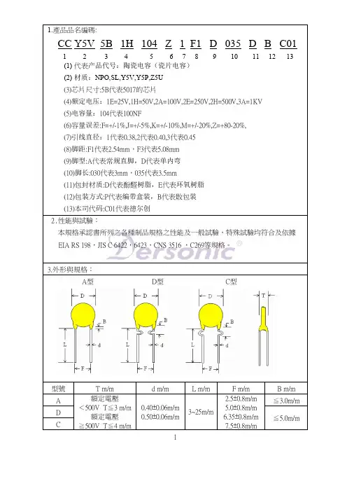
CT7交流瓷片电容规格书
- 格式:pdf
- 大小:524.41 KB
- 文档页数:5
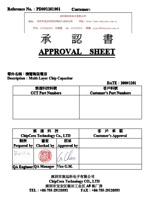
承認書APPROVAL SHEET零件名稱:積層陶瓷電容Description :Multi-Layer Chip CapacitorDATE :20020099/1201深圳市宸远科电子有限公司ChipCera Technology CO.,LTD 深圳市宝安区银田工业区A9栋厂房TEL :+86-7+86-7555555--29120592FAX :+86-7+86-7555555--29120593Reference No.:PD0PD091201912019120100000011Customer Customer::宸遠科技料號CCT Part Numbers客戶料號Customer Customer’’s Part Numbers 宸遠科技ChipCera Technology Co.,LTD 客戶承認Customer Customer’’s Approval 製表Prepared by 審查Checked by 核准Approved byEngineer QA Manager Vice G.M.Tolerance Capacitance for dielectricA=±0.05pF B=±0.10pF C=±0.25pF D=±0.50pF F=±1.0% G=±2.0% J=±5.0% K=±10% M=±20%NP0X7R X5R Y5V 10pF and below More than10pF100pF~1μF(101~105)1uf~100uf(105~107)10nF~10uF(103~106) B,C,D G,J J,K,M K,M M,ZProduct dimensions in mm.X7R SeriesX7R/X5R SeriesY5V Series7Resistance tosoldering heatPreheat the capacitor at120℃to150℃for1minute.Immerse the capacitor in an eutectic soldersolution at270270±±5℃for1010±±1seconds.After set it atroom temperature for2424±±2hours(temperaturecompensation type)or4848±±4hours(high dielectricconstant type),then measure.*High dielectric constant type:Initial measurement of X7RX7R/X5R/X5R and Y5V.Perform a heat treatment at150150±±5℃for one hourand then set it at room temperature for4848±±4hours.Perform the initial measurement.Dielectric NP0X7RX7R//X5RY5VAppearance No defectCapacitanceChange<±2.5%or<±0.25pF±7.5%±20%DF The same as No.2IRMore than500500ΩΩ-F(whichever is smaller)DielectricStrengthNo failure8Resistance toleachingThe capacitors are dipped into the solder at260260±±5℃for3030±±1seconds,and then check the solderingby measuring the areas covered with solder.95%of the terminations are to be soldered evenly andcontinuously.9Solder ability ofterminationZero hour test,and test after storage(20to24months)in original atmosphere in normalatmosphere;un-mounted chips completelyimmersed for2±0.5s in a solder bath of235±5℃.95%of the termination is to be soldered evenly andcontinuously.10Rapid change oftemperatureNPO/X7R:-55℃to+125℃,5cycleX5R:-55℃to+85℃,5cycleY5V:-25℃to+85℃,5cycleDuration:30mins.Recovery:24±2hrs.No visible damage after24h recoveryClass I NPO:∆C/C≤2.5%or±0.25pFClassⅡX7RX7R/X5R/X5R/X5R::∆C/C≤±15%Y5V:∆C/C≤±20%11Damp heat,steadystate500±12hours at40±2℃;90to95%RHNo visible damage after24±2(NPO)or48±4hoursrecoveryClassⅠ(NPO)1.∆C/C±5%or1pF,whichever is greater2.C<10pF;Q≥200+10C10≤C≤30pF;Q≥275+5/2CC>30pF;Q≥3503.IR≥4000MΩorRiCR≥4040ΩΩF,whichever is lessClassⅡ(X7R(X7R/X5R/X5R/X5R))1.∆C/C within±15%2.2.tantanδ≤7%3.3.R R≥2000MΩorRiCR≥5050ΩΩF,whichever is lessClassⅡ(Y5V)1.∆C/C within±30%2.50/25V:tanδ≤9%16V:tanδ≤12.5%10V:tanδ≤15%3.IR≥2000MΩorRiCR≥5050ΩΩF,whichever is less12Endurance 1000h at maximum temperatureVr(rated voltage)≤250VAt2×V rVr(rated voltage)=500VAt1.5VrVr(rated voltage)>500VAt1.2VrC>0..1UF,At1.5VrNo visible damage after24±2(NPO)or48±4hoursrecoveryClass1(NPO)1.∆C/C±2%or1pF,whichever is greater2.tanδ≤2x specified value3.IR≥4000MΩor RiCR≥4040ΩΩF,whichever is lessClass2(X7R(X7R/X5R/X5R/X5R))1.∆C/C within±15%2.tanδ≤7%3.IR≥2000MΩor RiCR≥5050ΩΩF,whichever is lessClass2(Y5V)1.∆C/C within±30%2.50/25V:tanδ≤9%16V:tanδ≤12.5%3.IR≥2000MΩor RiCR≥5050ΩΩF,whichever is lessAll dimensions in mmSize SymbolABPLT(Paper)T(Embossed)04020.62±0.05 1.12±0.05 2.00±0.058.00±0.200.60±0.05N/A 0603 1.10±0.10 1.90±0.10 4.00±0.108.00±0.20 1.00±0.05N/A 0805 1.65±0.05 2.40±0.05 4.00±0.108.00±0.20 1.00±0.05N/A 1206 2.00±0.10 3.50±0.10 4.00±0.108.00±0.20 1.00±0.05Max.2.01210 2.80±0.20 3.70±0.20 4.00±0.108.00±0.20N/A Max.2.01808 2.50±0.30 4.90±0.30 4.00±0.1012.0±0.20N/A Max.2.518123.60±0.304.90±0.308.00±0.1012.0±0.20N/AMax.2.5Paper Tape T ≦1.1mmEmbossed Tape T ≦2.60mm8.4+1.5/-0 All dimensions in mm6.1Capacitor ClassificationMulti-layer ceramic capacitors are available in wide range of characteristics.Electronic Industries Association (EIA)and the military have established categories to help divide the basic characteristics into more easily specified classes.The basic indu industrystry specification for ceramic capacitor is EIA specification RS-198and as noted in the general section,it specifies temperature-compensating capacitors as class I capacitors.These are specified by the military under specification MIL-C-20.General-pur General-purposepose capacitors with non-linear temperature coefficients are called Class II capacitors by EIA and specified by military under MIL-C-11015and MIL-C-39014.The new high reliability military specification,MIL-C-123covers both class Iand class II dielect dielectrics.rics.Class I —Class I capacitors or temperature-compensating capacitors are usually made from mixtures of titanates where barium titanate is normally not a major part of mix.They have predictable temperature coefficients and in general,do not have an aging characteristic.Thus they are the most stable capacitor available.Normally the T.C.s of Class I temperature-compensating capacitors are NP0(±30ppm/℃).Class II —General-purpose ceramic capacitors are called Class II capacitors and have become extremely popular because of the high capacitance values available in very small size.These capacitors are ferroelectrics and vary in capacitance value under the influence of the environmental and electrical operating conditions.Class II capacitors are affected by temperature 、voltage 、frequency and time.Temperature effects for Class II ceramic capacitors are exhibited as non-linear capacitancechanges with tem temperature.perature.Industry standards for Mid-K dielectrics,such as X7R X7R/X5R /X5R and High-K dielectrics,such as Z5U Z5U..6.2The Characterization of MaterialsThe T.C curve of each material (for reference)DesignationClass Temperature Range (℃)Temp.Characteristics NPO(COG)I -55~+125±30ppm/℃X7RII -55~+125±15%X5RII -55~+85±15%Y5V II -25~+85-82~+22%6.3Recommend IR reflow and wave solderng profile(Pb-Free)Typical profile band of IR reflow Typical profile band of wave soldering。
本目录仅为提 供有关信息,内容会因技术、标准和工艺的变更而有所变动,且不会因此而预先通知,实时信息请与本公司或本公司授权的代理商联络。
相关部门R创 新 改 变 世 界Innovation changes the worldThe catalogue is for your reference only, Zhaozheng reserves the right to change the content without notice due to the change of technology, standard and technique. For updated information, please contact us or our authorized 产品目录Catalogue资质证书Certifications附录AppendixGYC7 Capacity changeover contactors配件、附件Parts/accessories尺寸、技术寿命特性Dimension\durability\characteristics1/24/3032/4244/4748/5758/6364/6869/9596/113114/127总目录Contents选型指南Selection guideGYC1系列交流接触器GYC1 ContactorsGYC2系列交流接触器GYC2 ContactorsGYC3系列永磁锁扣交流接触器GYC3 Permanent magnetic latching contactorsGYC5系列交流接触器GYC5 ContactorsGYC6系列交流接触器GYC6 ContactorsGYC7系列切换电容交流接触器GYC1GYC2115-800200-1600*GYC2115、150、170GYC3115-630型号GYC51000-3200——GYC6750-1800800-2750GYC7——型号ContactorGYC1系列交流接触器GYC1 Contactors选型指南Selection guide特性Characteristics结构Scheme联锁接触器Interlocked contactors 目录Contents5/67/101112/3适用于交流50\60Hz,电压至1000V,电流至1600A电路中控制各种类型的电动机,控制电阻、电感和电容性电路:加热、照明、功率补偿、变压器控制配电电路、工业配电,绿色电源配电对于动作频繁,使用条件恶劣,建议使用快速动作线圈应用Applications注:1)详见附录MNote: 1) details refer to appendix MGYC1系列接触器选型指南Selection guideIn circuit of AC 50\60Hz, voltage up to 1000V, current up to 600A, controlling motors of different types.Control resistance,inductive,capacitive loads:heating,lighting,power compensation and transformerControl distribution circuit, industrial distribution, green energy distributionFor harsh environment and frequent operations, quick operating coils are recommend 115至800AGYC1 Contactors From 115 to 800A.GYC1系列接触器选型指南Selection guide115至800AGYC1 Contactors From 115 to 800AGYC1系列接触器115至800A控制电路:交流或直流供电 AC/DCGYC1 Contactors From 115 to 800A Array(1) Sinusoidal without interference.GYC1系列接触器115至800A控制电路:交流或直流供电 AC/DC9特 性Characteristic 2)接触器GYC1 115到630可单独提供连接端子防护罩。
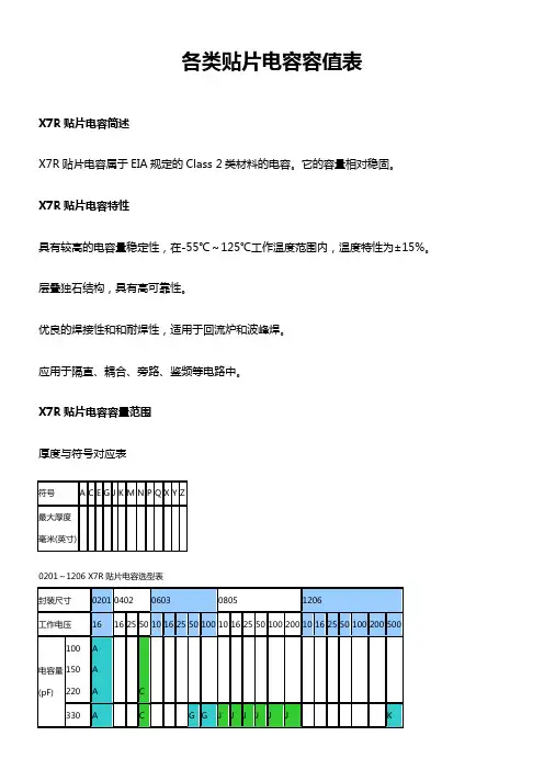
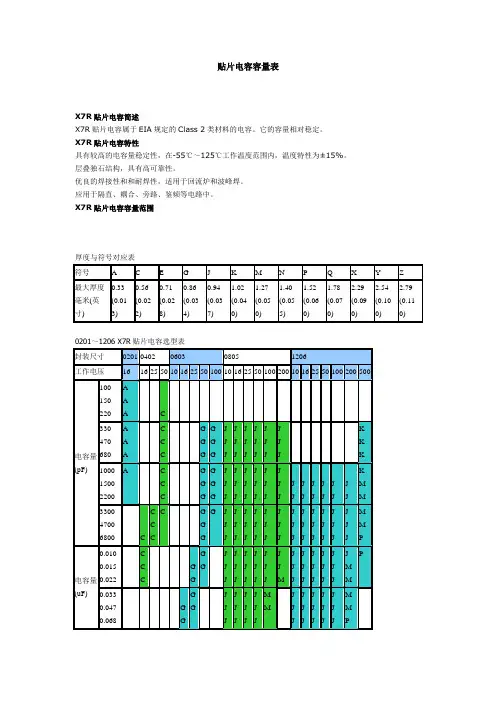
各类贴片电容容值表X7R贴片电容简述X7R贴片电容属于EIA规定的Class 2类材料的电容。
它的容量相对稳固。
X7R贴片电容特性具有较高的电容量稳定性,在-55℃~125℃工作温度范围内,温度特性为±15%。
层叠独石结构,具有高可靠性。
优良的焊接性和和耐焊性,适用于回流炉和波峰焊。
应用于隔直、耦合、旁路、鉴频等电路中。
X7R贴片电容容量范围厚度与符号对应表0201~1206 X7R贴片电容选型表1210~2225 X7R贴片电容选型表NPO COG 贴片电容容量规格表2009-07-15 16:28 阅读354 评论1 字号:大中小NPO(COG)贴片电容属于Class 1温度补偿型电容。
它的容量稳定,几乎不随温度、电压、时间的变化而变化。
尤其适用于高频电子电路。
具有最高的电容量稳定性,在-55℃~125℃工作温度范围内,温度特性为:0±30ppm/℃(COG)、0±60ppm/℃(COH)。
层叠独石结构,具有高可靠性。
优良的焊接性和和耐焊性,适用于回流炉和波峰焊。
应用于各种高频电路,如:振荡、计时电路等。
咱们把用来制造片式多层瓷介电容(MLCC)的陶瓷叫电容器瓷。
那个地址所说的瓷介确实是用电容器瓷制成的陶瓷介质。
大伙儿明白,陶瓷是一类质硬、性脆的无机烧结体。
就其显微结构而论,多数具有多晶多相结构。
其性能往往决定于其成份和结构。
当配方确信以后,可否达到预期的成效,关键取决于制造陶瓷粉料的工艺。
按其用途能够分为三类:①高频热补偿电容器瓷(UJ、SL);②高频热稳固电容器瓷(NPO);③低频高介电容器瓷(X7R、Y5V、Z5U)。
按温度系数分能够分为两类:①负温度系数电容器瓷(即高频热补偿电容器瓷);②正温度系数电容器瓷(即平常咱们常说的COG、X7R、Y5V瓷料)。
按工作频率能够分为三类:低频、高频、微波介质。
高频热补偿、热稳固电容器瓷是专供Ⅰ类瓷介电容器作介质用,其瓷料要紧成份是MgTiO3、CaTiO3、SrTiO3和TiO2再加入适量的稀土类氧化物等配制而成。
贴片电容容量表X7R贴片电容简述X7R贴片电容属于EIA规定的Class 2类材料的电容。
它的容量相对稳定。
X7R贴片电容特性具有较高的电容量稳定性,在-55℃~125℃工作温度范围内,温度特性为±15%。
层叠独石结构,具有高可靠性。
优良的焊接性和和耐焊性,适用于回流炉和波峰焊。
应用于隔直、耦合、旁路、鉴频等电路中。
X7R贴片电容容量范围厚度与符号对应表0201~1206 X7R贴片电容选型表1210~2225 X7R贴片电容选型表NPO COG 贴片电容容量规格表默认分类 2009-07-15 16:28 阅读354 评论1字号:大大中中小小NPO(COG)贴片电容属于Class 1温度补偿型电容。
它的容量稳定,几乎不随温度、电压、时间的变化而变化。
尤其适用于高频电子电路。
具有最高的电容量稳定性,在-55℃~125℃工作温度范围内,温度特性为:0±30ppm/℃(COG)、0±60ppm/℃(COH)。
层叠独石结构,具有高可靠性。
优良的焊接性和和耐焊性,适用于回流炉和波峰焊。
应用于各种高频电路,如:振荡、计时电路等。
我们把用来制造片式多层瓷介电容(MLCC)的陶瓷叫电容器瓷。
这里所说的瓷介就是用电容器瓷制成的陶瓷介质。
大家知道,陶瓷是一类质硬、性脆的无机烧结体。
就其显微结构而论,大都具有多晶多相结构。
其性能往往决定于其成份和结构。
当配方确定之后,能否达到预期的效果,关键取决于制造陶瓷粉料的工艺。
按其用途可以分为三类:①高频热补偿电容器瓷(UJ、SL);②高频热稳定电容器瓷(NPO);③低频高介电容器瓷(X7R、Y5V、Z5U)。
按温度系数分可以分为两类:①负温度系数电容器瓷(即高频热补偿电容器瓷);②正温度系数电容器瓷(即平时我们常说的COG、X7R、Y5V瓷料)。
按工作频率可以分为三类:低频、高频、微波介质。
高频热补偿、热稳定电容器瓷是专供Ⅰ类瓷介电容器作介质用,其瓷料主要成分是MgTiO3、CaTiO3、SrTiO3和TiO2再加入适量的稀土类氧化物等配制而成。
电子基础知识——电容篇1、电容在电路中一般用“C”加数字表示(如C25表示编号为25的电容)。
电容是由两片金属膜紧靠,中间用绝缘材料隔开而组成的元件。
电容的特性主要是隔直流通交流。
电容容量的大小就是表示能贮存电能的大小,电容对交流信号的阻碍作用称为容抗,它与交流信号的频率和电容量有关。
容抗XC=1/2πf c (f表示交流信号的频率,C表示电容容量)电话中常用电容的种类有电解电容、瓷片电容、贴片电容、独石电容、钽电容和涤纶电容等。
2、识别方法:电容的识别方法与电阻的识别方法基本相同,分直标法、色标法和数标法3种。
电容的基本单位用法拉(F)表示,其它单位还有:毫法(mF)、微法(uF)、纳法(nF)、皮法(pF)。
其中:1法拉=1000毫法=1000000微法=1000000000纳法=1000000000000皮法容量大的电容其容量值在电容上直接标明,如10 uF/16V容量小的电容其容量值在电容上用字母表示或数字表示字母表示法:1m=1000 uF 1P2=1.2PF 1n=1000PF数字表示法:一般用三位数字表示容量大小,前两位表示有效数字,第三位数字是倍率。
如:102表示10×102PF=1000PF 224表示22×104PF=0.22 uF3、电容容量误差表符号F G J K L M允许误差±1% ±2% ±5% ±10% ±15% ±20%如:一瓷片电容为104J表示容量为0. 1 uF、误差为±5%。
4、故障特点在实际维修中,电容器的故障主要表现为:(1)引脚腐蚀致断的开路故障。
(2)脱焊和虚焊的开路故障。
(3)漏液后造成容量小或开路故障。
(4)漏电、严重漏电和击穿故障。
贴片电容的种类和特点单片陶瓷电容器(通称贴片电容)是目前用量比较大的常用元件,就AVX公司生产的贴片电容来讲有NPO、X7R、Z5U、Y5V等不同的规格,不同的规格有不同的用途。
序号厂家料号描绘1B420 0200223瓷片电容20200228瓷片电容1000V 101±302002289 瓷片电容 1000V 101 ±编带40200277瓷片电容1000V222±20%成形50200303瓷片电容1000V 222±60200336瓷片电容1000V 472± 20% 5mm70200224瓷片电容80200255瓷片电容1000V 103 +80%-20%成形902002249 瓷片电容编带100200304陶瓷电容1000V 103±20% NPO10mm0200333瓷片电容500V33P±10% NPO成型5mm0200232瓷片电容500V 101±10% 5MM0200166瓷片电容500V 103±20% 5mm 110200009瓷片电容50V 8P±120200012瓷片电容50V 10P±1302003159 瓷片电容 50V 10P±10%成形 5mm编带140200015瓷片电容50V 15P±1502003489 瓷片电容 50V 15P ±5% NPO 5mm编带160200164瓷片电容50V 20P±170200167瓷片电容50V 20P±180200052瓷片电容50V 22P±190200305瓷片电容50V 22P±10%成形5mm2002003059 瓷片电容 50V 22P±10%成形 5mm编带210200020瓷片电容50V 30P±220200288瓷片电容50V 30P±10%5MM230200211瓷片电容50V 30P±240200212瓷片电容50V 30P±250200331瓷片电容50V 30P±10%成形5mm270200022瓷片电容50V 33P±280200053瓷片电容50V 47P±290200152瓷片电容50V 47P±10% 5MM300200036瓷片电容50V 47P±10% NPO 5MM310200035瓷片电容50V 47P±5% NPO 5MM320200306瓷片电容50V 47P±10%成形5mm3302003069 瓷片电容 50V 47P±10%成形 5mm编带340200028瓷片电容50V 68P±350200057瓷片电容50V 82P±370200059瓷片电容50V 101±380200105瓷片电容50V 101±10% 5MM390200060瓷片电容50V 101±400200058瓷片电容50V 101±4102000589 瓷片电容 50V 101 ±5% 2.5mm 编带420200039瓷片电容50V 101±5% NPO 5MM430200307瓷片电容50V 101±10%成形5mm4402003079 瓷片电容 50V 101±10%成形 5mm编带材质瓷介类型试验温度SL 1类125℃SL 1类125℃SL 1类125℃Y5U 2类85℃Y5U 2类85℃Y5V 2类85℃Y5V 2类85℃Y5V 2类85℃Y5V 2类85℃Y5U 2类85℃NPO 1类125℃SL 1类125℃Y5V 2类85℃NPO 1类125℃NPO 1类125℃NPO 1类125℃NPO 1类125℃NPO 1类125℃NPO 1类125℃NPO 1类125℃NPO 1类125℃NPO 1类125℃NPO 1类125℃NPO 1类125℃SL 1类125℃SL 1类125℃NPO 1类125℃SL 1类125℃NPO 1类125℃N750 1类125℃N750 1类125℃NPO 1类125℃NPO 1类125℃N750 1类125℃N750 1类125℃NPO 1类125℃SL 1类125℃SL 1类125℃SL 1类125℃SL 1类125℃SL 1类125℃SL 1类125℃NPO 1类125℃SL 1类125℃SL 1类125℃450200106瓷片电容50V101+80%-20% 5MM 460200061瓷片电容50V 121±470200061瓷片电容50V 121±480200041瓷片电容50V 151±10% NPO 5mm 490200062瓷片电容50V 151±500200330瓷片电容50V151±10%成形5mm 5102003309 瓷片电容 50V151±10% 成形 5mm编带520200066瓷片电容50V 221±530200109瓷片电容50V 221±10% 5MM 540200065瓷片电容50V 221±550200308瓷片电容50V 221±10%成形5mm 5602003089 瓷片电容 50V 221±10%成形 5mm编带5702002939 瓷片电容 50V 271 ±10% 5mm编带580200046瓷片电容50V 271±5% NPO 5MM 590200069瓷片电容50V 331±600200111瓷片电容50V 331±10% 5MM 6102003099 瓷片电容 50V 331±10%成形 5mm编带620200192瓷片电容50V 471±630200312瓷片电容50V 471±10%成形5mm 6402003129 瓷片电容 50V 471±10%成形 5mm编带650200117瓷片电容50V 561 +80%-20% 5MM 660200071瓷片电容50V 561±6702003299 瓷片电容 50V561±10% 成形 5mm编带680200118瓷片电容50V 681±10% 5MM 6902001239 瓷片电容 50V 102 ±10% 5mm编带700200125瓷片电容50V 102 +80%-20% 5mm 710200077瓷片电容50V 102±720200123瓷片电容50V 102±10% 5MM 730200078瓷片电容50V 102±740200124瓷片电容50V 102±20% 5MM 750200332瓷片电容50V 102±10%成形5mm 7602003329 瓷片电容 50V 102±10%成形 5mm编带770200126瓷片电容50V 152±10% 5MM 7802001269 瓷片电容 50V 152±10%5mm编带790200154瓷片电容50V 272±10% 5MM 8002003179 瓷片电容 50V 332±10%成形 5mm编带8102001689 瓷片电容 50V 392 ±10% 5mm编带820200153瓷片电容50V 392±20% 5MM 830200088瓷片电容50V 472±8402001999 瓷片电容 50V 472 ±20% 5mm编带850200136瓷片电容50V 473±20% 5MM 8602003169 瓷片电容 50V 562±10%成形 5mm编带870200270瓷片电容50V 822±10% 5MM 8802003149 瓷片电容 50V 822±10%成形 5mm编带900200206瓷片电容50V 103 +80%-20% 5mm SL 1类125℃SL 1类125℃SL 1类125℃NPO 1类125℃SL 1类125℃SL 1类125℃SL 1类125℃SL 1类125℃SL 1类125℃SL 1类125℃SL 1类125℃SL 1类125℃Y5P 2类85℃Y5P 2类85℃Y5P 2类85℃Y5P 2类85℃Y5P 2类85℃Y5P 2类85℃Y5P 2类85℃Y5P 2类85℃Y5P 2类85℃Y5P 2类85℃Y5P 2类85℃Y5P 2类85℃Y5P 2类85℃Y5P 2类85℃Y5P 2类85℃Y5P 2类85℃Y5P 2类85℃Y5P 2类85℃Y5P 2类85℃Y5P 2类85℃Y5P 2类85℃Y5P 2类85℃Y5P 2类85℃Y5P 2类85℃Y5P 2类85℃Y5V 2类85℃Y5V 2类85℃Y5V 2类85℃Y5V 3类85℃Y5P 2类85℃Y5P 3类85℃Y5P 3类85℃Y5V 2类85℃910200174瓷片电容50V 103±920200131瓷片电容50V 103±10% 5MM930200092瓷片电容50V 103±940200132瓷片电容50V 103±20% 5MM950200310瓷片电容50V 103±10%成形5mm 9602003109 瓷片电容 50V 103±10%成形 5mm编带970200096瓷片电容50V 223±980200134瓷片电容50V 223±20% 5MM9902001349 瓷片电容 50V 223±20%5mm编带1000200100瓷片电容50V 473±10102001369 瓷片电容 50V 473±20% 5mm编带10202001369 瓷片电容 50V 473±20% 5mm编带1030200286瓷片电容50V 683±10% 5MM 10402002869 瓷片电容 50V 683±10%5mm编带1050200227瓷片电容50V 104±10% 5MM1060200178瓷片电容50V 104±1070200138瓷片电容50V 104±20% 5MM1080200318瓷片电容50V 104±20%成形5mm 1090200139瓷片电容50V 104+80%-20% 5MM 1100200313瓷片电容50V 104±10%成形5mm 11102003139 瓷片电容 50V 104±10%成形 5mm编带11202001389 瓷片电容 50V 104±20% 5mm编带11302003199 瓷片电容 50V104±10%成形 5mmφ8编带1140200281瓷片电容50V 154 +80%-20% 5MM 11502002819 瓷片电容 50V 154 +80%-20% 5mm编带1160200271陶瓷电容Y1 400V AC 221±10% 10MM 1170200381陶瓷电容@Y1 400VAC 221±10% 10mmCB 1180200343陶瓷电容Y1 400VAC 102±10% 10mm 1190200353陶瓷电容@Y1 400VAC 102±10% 10mm UL 1200200230陶瓷电容400VAC 102±10% 10mm 1210200225陶瓷电容400VAC 222±20% 10mm 1220200338CT7 400VAC 472 ±20% 2E4 10mm 1230200219陶瓷电容CT7 400V 103±20% 10MM 1240200267陶瓷电容CT81 250VAC221±20% 10mm 1250200268陶瓷电容CT81 250VAC221±10% 10mm 1260200349陶瓷电容CT7 250VAC 221±10% 10mm 1270200361陶瓷电容@CT81 250VAC221±20% 10 CQ 1280200362陶瓷电容@CT81 250VAC1290200229陶瓷电容CT81 250VAC471±10% 10mm 1300200385陶瓷电容@250VAC 222±20% 10mm CB 1310200177瓷片电容250V 223±20% 5mm132 2100061 CP线Φ133 ******** 瓷片电容 100V 152±10%5MM编带Y5P3类85℃Y5P3类85℃Y5U2类85℃Y5U2类85℃Y5P3类85℃Y5P3类85℃Y5U3类85℃Y5U3类85℃Y5U3类85℃Y5U3类85℃Y5U3类85℃Y5U3类85℃Y5P3类85℃Y5P3类85℃Y5P3类85℃Y5U3类85℃Y5U3类85℃Y5U3类85℃Y5V3类85℃Y5P3类85℃Y5P3类85℃Y5U3类85℃Y5P3类85℃Y5V3类85℃Y5V3类85℃Y5P2类85℃Y5P2类85℃Y5U2类85℃Y5U2类85℃Y5U2类85℃Y5U2类85℃Y5U2类85℃Y5V2类85℃Y5P2类85℃Y5P2类85℃Y5P2类85℃Y5P 2类 85℃85℃Y5P2类85℃Y5U2类85℃Y5V 2类 85℃85℃Y5P2类85℃。