超级电容产品规格书
- 格式:pdf
- 大小:1.52 MB
- 文档页数:11
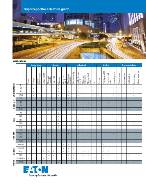
Lorem ipsum dolor sit amet Lorem ipsum dolor sit amet Lorem ipsum dolor sit ametApplicationsM o d u l e s C o i n c e l l sP a c k s L a r g e c e l l s S m a l l c y l i n d r i c a l H y b r i dSupercapacitor selection guideSmall cylindrical Features• Low resistance (ESR)• Wide operating temperatures • Extended operating temperature up to +85 °C with linear derating*• Fast charge/discharge• Highest power density Benefits• Long lifetimes, up to 20 years*• Maintenance free operation • Low total cost of ownership Applications• Smart utility meters• GPS and asset tracking devices • RF radios• Storage servers• Industrial backup/ride through • Automotive safety devices (emergency door locks, e-call)FamilyCapacitance(F)Part numberESR(mohm)Nominalvoltage (V)Leakagecurrent (μA)OperatingtemperatureSize(mm)0.22B0510-2R5224-R2000 2.52-25 °C to +70 °C 5 x 111.00B0810-2R5105-R5002.54-25 °C to +70 °C8 x 131.50B1010-2R5155-R3002.57-25 °C to +70 °C10 x 142.20B0820-2R5225-R200 2.59-25 °C to +70 °C8 x 203HB0820-2R5305-R155 2.57-25 °C to +70 °C8 x 205HB1020-2R5505-R95 2.511-25 °C to +70 °C10 x 206HB0830-2R5605-R95 2.511-25 °C to +70 °C8 x 3010HB1030-2R5106-R60 2.520-25 °C to +70 °C10 x 3015HB1325-2R5156-R45 2.522-25 °C to +70 °C13 x 2625HB1625-2R5256-R36 2.528-25 °C to +70 °C16 x 2535HB1635-2R5356-R28 2.532-25 °C to +70 °C16 x 3560HB1840-2R5606-R23 2.547-25 °C to +70 °C18 x 40110HB1860-2R5117-R18 2.5180-25 °C to +70 °C18 x 601HV0810-2R7105-R200 2.710-40 °C to +65 °C8 x 103HV0820-2R7305-R80 2.715-40 °C to +65 °C8 x 205HV1020-2R7505-R40 2.720-40 °C to +65 °C10 x 206HV0830-2R7605-R40 2.720-40 °C to +65 °C8 x 3010HV1030-2R7106-R34 2.723-40 °C to +65 °C10 x 3015HV1325-2R7156-R30 2.723-40 °C to +65 °C13 x 2625HV1625-2R7256-R27 2.745-40 °C to +65 °C16 x 2535HV1635-2R7356-R24 2.751-40 °C to +65 °C16 x 3535HV1245-2R7356-R20 2.751-40 °C to +65 °C12 x 4560HV1840-2R7606-R18 2.7110-40 °C to +65 °C18 x 40100HV1860-2R7107-R12 2.7260-40 °C to +65 °C18 x 603.3TV0820-3R0335-R75 3.015-40 °C to +65 °C8 x 206TV1020-3R0605-R35 3.013-40 °C to +65 °C10 x 2010TV1030-3R0106-R26 3.025-40 °C to +65 °C10 x 3015TV1325-3R0156-R24 3.035-40 °C to +65 °C13 x 2525TV1625-3R0256-R18 3.060-40 °C to +65 °C16 x 2534TV1245-3R0346-R16 3.075-40 °C to +65 °C12 x 4535TV1635-3R0356-R15 3.090-40 °C to +65 °C16 x 3560TV1840-3R0606-R13 3.0135-40 °C to +65 °C18 x 40100TV1860-3R0107-R11 3.0225-40 °C to +65 °C18 x 60 TVA25TVA1625-3R0256-R18 3.060-40 °C to +65 °C16 x 25 35TVA1635-3R0356-R15 3.090-40 °C to +65 °C16 x 3560TVA1840-3R0606-R13 3.0135-40 °C to +65 °C18 x 40100TVA1860-3R0107-R11 3.0225-40 °C to +65 °C18 x 60 BHBHVTVFamily Capacitance(F)Part numberESR(mohm)Nominalvoltage (V)Leakagecurrent (μA)Operatingtemperature Size (mm) 0.1PB-5R0(1)104-R4000 5.03-25 °C to +70 °C 5.5 x 10.8 x 12.50.47PB-5R0(1)474-R1000 5.07-25 °C to +70 °C8.5 x 16.8 x 141.0PB-5R0(1)105-R500 5.012-25 °C to +70 °C 8.5 x 16.8 x 21.51.5PHB-5R0(1)155-R310 5.010-25 °C to +70 °C8.5 x 16.8 x 21.52.5PHB-5R0(1)255-R190 5.014-25 °C to +70 °C10.5 x 20.8 x 22.53.0PHB-5R0(1)305-R190 5.016-25 °C to +70 °C8.5 x 16.8 x 31.5 5.0PHB-5R0(1)505-R120 5.025-25 °C to +70 °C 10.5 x 20.8 x 320.47PHV-5R4(1)474-R300 5.413-40 °C to +65 °C8.5 x 16.8 x 141.5PHV-5R4(1)155-R100 5.418-40 °C to +65 °C8.5 x 16.8 x 21.52.5PHV-5R4(1)255-R70 5.424-40 °C to +65 °C10.5 x 20.8 x 22.53.0PHV-5R4(1)305-R70 5.425-40 °C to +65 °C8.5 x 16.8 x 31.5 5.0PHV-5R4(1)505-R65 5.428-40 °C to +65 °C10.5 x 20.8 x 320.47PHVL-3R9(1)474-R400 3.91-40 °C to +65 °C 8.5 x 16.8 x 141.5PHVL-3R9(1)155-R160 3.92-40 °C to +65 °C 8.5 x 16.8 x 21.52.5PHVL-3R9(1)255-R803.94-40 °C to +65 °C 10.5 x 20.8 x 22.53.0PHVL-3R9(1)305-R80 3.94-40 °C to +65 °C 8.5 x 16.8 x 31.5 5.0PHVL-3R9(1)505-R70 3.95-40 °C to +65 °C 10.5 x 20.8 x 320.47PM-5R0(1)474-R420 5.08-40 °C to +60 °C8.5 x 16.8 x 141.0PM-5R0(1)105-R150 5.010-40 °C to +60 °C8.5 x 16.8 x 21.5 1.5PM-5R0(1)155-R70 5.015-40 °C to +60 °C10.5 x 20.8 x 22.53.0PM-5R0(1)305-R50 5.020-40 °C to +60 °C10.5 x 20.8 x 32 1.65PTV-6R0165(1)-R150 6.018-40 °C to +65 °C8.5 x 16.8 x 21.5 3.0PTV-6R0305(1)-R100 6.025-40 °C to +65 °C10.5 x 20.8 x 22.5 5.0PTV-6R0505(1)-R72 6.080-40 °C to +65 °C10.5 x 20.8 x 32Cylindrical packs Features• Integrated cell management/balancing bult-in• Low resistance (ESR)• Wide operating temperatures • Extended operating temperature up to +85 °C with linear derating*• Fast charge/discharge• High power densityBenefits• Long lifetimes, up to 20 years*• Maintenance free operation • Low total cost of ownership Applications• Smart utility meters• GPS and asset tracking devices • RF radios• Storage servers• Industrial backup/ride through • Automotive safety devices (emergency door locks, e-call)PBPHBPHVPMPTV1: “V” for straight leads, “H” for 90 degree bent leads PHVLHybrid supercapacitors Features• High power and ultra-high capacitance• Small footprints for space-saving (10.5 mm x 18 mm to 16.5 mm x 27 mm package sizes)• Wide range of operating temperatures (-25 °C to +70 °C)Benefits• Low ESR and leakage current to minimize power wastage• Lead and halogen-free, RoHS and REACH compliant,UL recognizedApplications• Industrial backup/ride through • Backup for storage servers• Water and gas smart meters • IoT energy storage• Medical backup power/alarm • Commercial trucks/containers asset tracking FamilyCapacitance(F)Part numberMaximuminitial ESRContinuouscurrentPeak current(A)Nominal leak-age currentPeak power(W) 10HS/HSL0814-3R8106-R15000.075 1.0 2.0/3.0 2.425HS/HSL0820-3R8256-R6500.125 2.3 2.5/3.3 5.530HS/HSL1016-3R8306-R5500.15 2.7 3.0/4.0 6.650HS/HSL1020-3R8506-R4500.25 3.4 4.0/5.08.070HS/HSL1025-3R8706-R2500.35 6.1 5.0/8.014120HS/HSL1225-3R8127-R2000.67.77.0/1218150HS/HSL1040-3R8157-R1400.7510.90.9/1626220HS/HSL1625-3R8227-R100 1.115.312/2536HS/HSLCoin cells Features• Multiple footprint configurations • Fully rated industrial operating temperature (KW/KVW family)• Eco-friendlyBenefits• Ultra low leakage current• Lower total install cost vs batteries with holders• Low total cost of ownership Applications• Real-time clock (RTC) backup • Memory backup• Utility meters• Medical devices• Industrial controls• Computers and peripherals • Network switches and routers • Appliances and white goodsFamilyCapacitance(F)Part numberESR(ohms)Nominalvoltage (V)Leakagecurrent (μA)OperatingtemperatureSize(mm)0.1KR-5R5C104-R75 5.50.6-25 °C to +70 °C13.5 x 7.50.22KR-5R5C224-R75 5.5 1.3-25 °C to +70 °C13.5 x 7.50.33KR-5R5C334-R50 5.52-25 °C to +70 °C13.5 x 7.50.47KR-5R5C474-R50 5.5 2.8-25 °C to +70 °C13.5 x 7.51.0KR-5R5C105-R30 5.56-25 °C to +70 °C21.5 x 7.51.0KVR-5R0C105-R30 5.010-25 °C to +70 °C21.3 x 8.11.5KR-5R5C155-R30 5.59-25 °C to +70 °C21.5 x 7.51.5KVR-5R0C155-R30 5.010-25 °C to +70 °C 21.3 x 8.10.1KR-5R5V104-R75 5.50.6-25 °C to +70 °C11.5 x 12.50.22KR-5R5V224-R75 5.5 1.3-25 °C to +70 °C11.5 x 12.50.33KR-5R5V334-R50 5.52-25 °C to +70 °C11.5 x 12.50.47KR-5R5V474-R50 5.5 2.8-25 °C to +70 °C11.5 x 12.51.0KR-5R5V105-R30 5.56-25 °C to +70 °C19 x 19.51.0KVR-5R0V105-R30 5.010-25 °C to +70 °C19.4 x 20.51.5KR-5R5V155-R30 5.59-25 °C to +70 °C19 x 19.51.5KVR-5R0V155-R30 5.010-25 °C to +70 °C 19.4 x 20.50.1KR-5R5H104-R75 5.50.6-25 °C to +70 °C11.5 x 50.22KR-5R5H224-R75 5.5 1.3-25 °C to +70 °C11.5 x 50.33KR-5R5H334-R50 5.52-25 °C to +70 °C11.5 x 50.47KR-5R5H474-R50 5.5 2.8-25 °C to +70 °C11.5 x 51.0KR-5R5H105-R30 5.56-25 °C to +70 °C19 x 6.51.5KR-5R5H155-R30 5.59-25 °C to +70 °C19 x 6.51.5KVR-5R0H155-R30 5.010-25 °C to +70 °C 19 x 19.50.1KW-5R5C104-R50 5.50.6-40 °C to +85 °C13.5 x 8.30.22KW-5R5C224-R50 5.5 1.3-40 °C to +85 °C13.5 x 8.30.33KW-5R5C334-R50 5.52-40 °C to +85 °C13.5 x 8.30.68KW-5R5C684-R30 5.5 2.8-40 °C to +85 °C21.5 x 9.00.68KVW-5R0C684-R30 5.010-40 °C to +85 °C21.3 x 111.0KW-5R5C105-R30 5.56-40 °C to +85 °C21.5 x 9.01.0KVW-5R0C105-R30 5.010-40 °C to +85 °C21.3 x 11 KR/KVR(cylindrical mounting)KR/KVR(vertical mounting)KR/KVR(horizontal mounting)KW/KVW(cylindrical mounting)Large cells Features• Low resistance (ESR), high power• Wide operating temperatures • Extend operating temperature up to +85 °C with linear derating*• Highest energy storage power densityBenefits• Long lifetimes, up to 20 years*• Maintenance free operation• Low total cost of ownership• No C-rate charge/discharge limitationsApplications• Engine and generator starting • Automotive active suspension • X-ray peak power• Material handling systems• Rail/Traction energy regeneration • Industrial backup power/UPS FamilyCapacitance(F)Part numberESR(mohm)Nominalvoltage (V)Leakagecurrent (μA)OperatingtemperatureSize(mm) 300XB3550-2R5307-R7.0 2.5300-25 °C to +70 °C35 x 50400XB3560-2R5407-R 4.5 2.5400-25 °C to +70 °C35 x 60600XB3585-2R5607-R 3.7 2.5700-25 °C to +70 °C 35 x 85300XV3550-2R7307-R 4.5 2.7480-40 °C to +65 °C35 x 50400XV3560-2R7407-R 3.2 2.7650-40 °C to +65 °C35 x 60600XV3585-2R7607-R 2.6 2.71300-40 °C to +65 °C 35 x 85275XT3550-3R0287-R 4.5 3.0600-40 °C to +65 °C36 x 54370XT3560-3R0377-R 3.2 3.0850-40 °C to +65 °C36 x 64555XT3585-3R0567-R 2.6 3.01300-40 °C to +65 °C 36 x 88.53000XL60-2R7308W-R0.23 2.75000-40 °C to +65 °C60 x 1383000XL60-2R7308T-R0.23 2.75000-40 °C to +65 °C60 x 1383400XL60-2R9348W-R0.23 2.858000-40 °C to +65 °C 60 x 1383400XL60-2R9348T-R0.23 2.858000-40 °C to +65 °C60 x 1383000XL60-3R0308W-R0.23 3.07000-40 °C to +65 °C60 x 1383000XL60-3R0308T-R0.23 3.07000-40 °C to +65 °C60 x 138 XBXVXTXL60Eaton is a registered trademark. All other trademarks are property of their respective owners.EatonElectronics Division 1000 Eaton Boulevard Cleveland, OH 44122United States/electronics © 2022 EatonAll Rights Reserved Publication No. 10594 July 2022Features• Integrated cell balancing and management• Wide operating temperatures • Simply wire in series and/or parallel to meet load needs •Highest energy storage power densityBenefits• Long lifetimes, up to 20 years*• Maintenance free operation • Low total cost of ownership•No C-rate type charge/discharge limitationsApplications• UPS backup power• Grid services & renewable firming• Commercial xEVs• Large material handling systems •Rail/Traction energy regenerationModulesFamilyCapacitance (F)Part number ESR(mΩ)Nominal voltage (V)Leakagecurrent (mA)Operating temperatureSize (mm)65XVM-16R2656-R 2216.223-40 °C to +65 °C 236 x 46 x 7862XTM-18R0626-R 2218.023-40 ° to +65 °C 236 x 46 x 78130XLM-62R1137A-R 6.762.1128-40 °C to +65 °C 686 x 176 x 173130XLM-62R1137A-T 6.762.1128-40 °C to +65 °C 686 x 176 x 173130XLM-62R1137B-R 6.762.1 5.2-40 °C to +65 °C 686 x 176 x 173130XLM-62R1137B-T 6.762.1 5.2-40 °C to +65 °C 686 x 176 x 173130XLM-69R0137A-R 6.769144-40 °C to +65 °C 686 x 176 x 173130XLM-69R0137A-T 6.769144-40 °C to +65 °C 686 x 176 x 173 130XLM-69R0137B-R 6.7697.0-40 °C to +65 °C 686 x 176 x 173130XLM-69R0137B-T 6.7697.0-40 °C to +65 °C 686 x 176 x 173166XLR-48R6167-R 5.048.6 5.2-40 °C to +65 °C 420 x 195 x 176188XLR-51R3187-R 5.051.38.0-40 °C to +65 °C 420 x 195 x 176500XLR-16R2507-R1.716.25.0-40 °C to +65 °C 416 x 67 x 1764.17XVM-259R2425-R 310259.227-40 °C to +65 °C 550 x 266 x 696.25XVM-259R2635-R 250259.228-40 °C to +65 °C 550 x 266 x 942.56XVM-315R9255-R 530315.923-40 °C to +65 °C 440 x 377 x 603.42XVM-315R9345-R 380315.924-40 °C to +65 °C 440 x 377 x 705.13XVM-315R9515-R 320315.925-40 °C to +65 °C 440 x 377 x 95XVM-16XTM-18XLMXLRXVM PCBAs* Supercapacitor lifetimes vary based on charge voltage and temperature. See Eaton’s application guidelines or contact your local Eaton sales representative for more information on lifetime estimates.XLR-LV。
R & D May.06. 2019 Paul LinR & DMay.06. 2019Matt ChienR & DMay.06. 2019Vera Huang1. Part Number System 料号说明Product Code Guide –SVLT Series (-25~+85 ℃ 0.1F~1.50F) For example:① SCM means supercapacitor module ② Supercapacitor Type: D means EDLC type ③ Series : VLT means SVLT series -25~+85 ℃ ④ Rated Voltage : 5R5 means 5.5 V / 3R6 means 3.6V ⑤ Rated Capacitance:For example:⑥ Capacitance Tolerance:⑦ Lead Form & & ⑧ Dimension Code:⑨ ⑩ Special Notes: Defaulted without any note2. Product Dimensions: 产品尺寸SCM □□□ ① D □ ② VLT □□□ ③ 5R5 □□□ ④ 334 □□□ ⑤ Z □ ⑥ VH □□ ⑦ 115004□□□□□□ ⑧ E □ ⑨ XX □□ ⑩ HTYPE3.General Characteristics/一般特性4.Environmental Characteristics/环境特性5.Test Methods 测试方法5.1Capacitance 容量Charge capacitor with constant current to rated voltage, then charge it with constant voltage for 30 minutes, and then discharge it with constant current to 0.1V (safe voltage). 将电容器恒流充至额定电压,并恒压30min,然后恒流放至0.1V(安全电压)Recording time t1 and t2 corresponding to V2 and V1 during discharge(where V2=80%VR, V1=40%VR)。
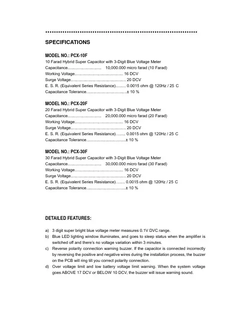
....................................................................... SPECIFICATIONSMODEL NO.: PCX-10F10 Farad Hybrid Super Capacitor with 3-Digit Blue Voltage Meter Capacitance.............................. 10,000.000 micro farad (10 Farad)Working Voltage........................................... 16 DCVSurge Voltage................................................. 20 DCVE. S. R. (Equivalent Series Resistance)......... 0.0015 ohm @ 120Hz / 25°CCapacitance Tolerance....................................± 10 %MODEL NO.: PCX-20F20 Farad Hybrid Super Capacitor with 3-Digit Blue Voltage Meter Capacitance.............................. 20,000.000 micro farad (20 Farad)Working Voltage........................................... 16 DCVSurge Voltage................................................. 20 DCVE. S. R. (Equivalent Series Resistance)…..... 0.0015 ohm @ 120Hz / 25°CCapacitance Tolerance...................................± 10 %MODEL NO.: PCX-30F30 Farad Hybrid Super Capacitor with 3-Digit Blue Voltage Meter Capacitance.............................. 30,000.000 micro farad (30 Farad)Working Voltage........................................... 16 DCVSurge Voltage................................................. 20 DCVE. S. R. (Equivalent Series Resistance)……. 0.0015 ohm @ 120Hz / 25°CCapacitance Tolerance...................................± 10 %DETAILED FEATURES:a) 3 digit super bright blue voltage meter measures 0.1V DVC range.b) Blue LED lighting window illuminates, and goes to sleep status when the amplifier isswitched off and there’s no voltage variation within 3 minutes.c) Reverse polarity connection warning buzzer. If the capacitor is connected incorrectlyby reversing the positive and negative wires during the installation process, the buzzer on the PCB will ring till you correct polarity connection.d) Over voltage limit and low battery voltage limit warning. When the system voltagegoes ABOVE 17 DCV or BELOW 10 DCV, the buzzer will issue warning sound.INSTALLATION AND MOUNTING:Securely mount the capacitor using supplied hardware. Be careful when choosing mounting location to avoid moving parts and possible exposure to moisture.CHARGING THE CAPACITOR AND WIRING:The capacitor must be charged before connecting the Power and Ground cables to the capacitor. Failure to charge the capacitor will result in a large spark generated from the rapid inflow of current.1. To charge the capacitor:Make capacitor positive terminal connections with amplifier and tighten the bolt. Do not over-tighten the bolt!Caution: Stripped terminals are not covered under the capacitor’s warranty.2. Connect the ground cables of the battery, amplifier, and capacitor separately tochassis.3. Place the supplied charging resistor between the positive terminal of the capacitor andthe battery’s positive terminal. After 5~60 seconds, the capacitor will be fully charged.Caution: The resistor will become hot!4. Immediately after the charging process, take away the charging bulb from theconnecting wire, and connect the positive cable to the positive terminal on the capacitor.CAPACITOR WIRING DIAGRAM:DISCHARGING THE CAPACITOR:Never remove the capacitor without discharging the stored power – it can give adangerous electrical shock!To disconnect the capacitor, follow these instructions:1. Disconnect the cables from the capacitor in the following order:a) positive (+) cableb) ground (-) cable2. Holding the resistor provided, touch the leads to the positive (+) and ground (-)terminals of the capacitor. After 1~5 minutes, the capacitor will be discharged (Thecharging resistor will become hot!) Then you can safely remove and handle it.WARNING!!THIS POWER CAPACITOR MAY EXPLODE AND CAUSE SERIOUS INJURY IF ABUSEDOR CONNECTED IMPROPERLY. PLEASE REFER TO THE INSTRUCTIONS CONTAINEDIN THIS MANUAL FOR CORRECT OUNTING, CHARGING/DISCHARGING AND WIRINGCONNECTION FOR THIS CAPAPCITOR PRIOR TO INSTALLATION.POWER ACOUSTIK AUDIO ACCESSORIES CAR AUDIO ACCESSORIES。
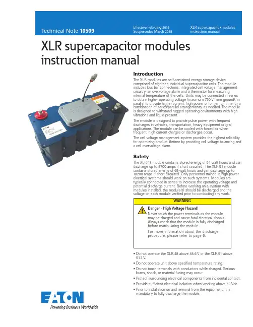
10509XLR supercapacitor modules instruction manualSafetyThe XLR-48 module contains stored energy of 54 watt-hours and can discharge up to 9700 amps if short circuited. The XLR-51 module contains stored energy of 69 watt-hours and can discharge up to 10200 amps if short circuited. Only personnel trained in high power electrical systems should work on such systems. Modules are typically connected in series to increase the operating voltage and potential discharge current. Before working on a system with modules installed, the module(s) should be discharged and the voltage on each module verified prior to conducting any work.IntroductionThe XLR modules are self-contained energy storage devicecomprised of eighteen individual supercapacitor cells. The module includes bus bar connections, integrated cell voltage management circuitry, an overvoltage alarm and a thermistor for measuringinternal temperature of the cells. Units may be connected in series to obtain higher operating voltage (maximum 750 V from ground), in parallel to provide higher current, high power or longer run time, or a combination of series/parallel arrangements, as needed. The module is designed to withstand rugged operating environments with high vibrations and liquid present.The module is designed to provide pulse power with frequent discharges in vehicles, transportation, heavy equipment or grid applications. The module can be cooled with forced air when frequent, high current charges or discharges occur.The cell voltage management system provides the highest reliability for optimizing product lifetime by providing cell voltage balancing and a cell overvoltage alarm.• D o not operate the XLR-48 above 48.6 V or the XLR-51 above 51.3 V .• D o not operate unit above specified temperature rating.• D o not touch terminals with conductors while charged. Serious burns, shock, or material fusing may occur.•P rotect surrounding electrical components from incidental contact.• P rovide sufficient electrical isolation when working above 50 Vdc.• P rior to installation on and removal from the equipment, it is mandatory to fully discharge the module.2Technical Note 10509Effective February 2019XLR supercapacitor modules instruction manualEATON /electronicsTheory of operationSupercapacitors function on electrostatic principles with no chemical reactions and no moving parts. They avoid the lifetime issuesassociated with chemical storage of batteries or mechanical issues associated with fly wheels. The XLR modules are non-toxic and designed for years of maintenance-free operation.Supercapacitors are intended as energy storage with a DC discharge. The module should not be used for AC charging ordischarging. Discharges may be constant current or constant power. Example discharges are shown in Figure 1a and 1b. The voltage of the module drops linearly under a constant current discharge.Figure 1a. E xample voltage and current discharge curves for 5 kW discharge fromone module with 48 V float voltage.S y s t e m V o l t a g e (V o l t s )S y s t e m C u r r e n t (A m p s )504030201002502001501005000 5 10 15 20Time (seconds)Discharge Current (A)Voltage (V)Figure 1b. E xample voltage and current discharge curves for 250 A discharge fromone module with 48 V float voltage.S y s t e m V o l t a g e (V o l t s )S y s t e m C u r r e n t (A m p s )50403020103503002502001501005000 5 10 15 20Time (seconds)Discharge Current (A)Voltage (V)Due to the very low equivalent series resistance (ESR) of the supercapacitors, minimal heat is generated during operation. However, as supercapacitors can handle very high currents, a significant heat rise can occur if the discharges and re-charging is frequent and above 50 Arms continuous current.Most systems require multiple modules connected in series to reach higher operating voltages. The XLR module can be series connected for operation up to 750 V (with respect to ground) to meet system level requirements and connected in parallel without limit to meet longer discharge times.Due to manufacturing variations in capacitance and leakage current, cells in a module can differ in voltage. This voltage difference affects the capacitance and equivalent series resistance over time and results in a shortening of the life of the system.The shunt balance circuit monitors the voltage of each cell. When the voltage on a cell exceeds 2.65 V preset in the XLR-48 and 2.95 V preset in the XLR-51, the balancing circuit will activate to discharge the cell back to appropriate levels.Figure 2. F our mounting points for the module.The module has 4 M8 mounting holes, as shown in Figure 2 and 3. A spacer may be needed between the top and bottom plate in high vibration environments. In moderate or low vibration environments, only the holes on the top or bottom plate are required for securing the module.369.2Negative T erminal M10196170.077Figure 3. D imensional drawing of module, all dimensions in mm.InstallationUnpackingInspect the shipping carton for signs of damage prior to unpacking the module. Damage to the shipping carton or module should be reported to the carrier immediately.Remove the module from the shipping carton and retain the shipping materials until the unit has been inspected and is determined to be operational.NOTE: The original shipping materials are approved for both air and ground shipment. The module should be removed from the shipping carton by lifting it by the body of the module.Contents:1 M odule1 M10 bolt, washer, lock washer (inserted into negative terminal)1 M8 bolt, washer, lock washer (Inserted into positive terminal)1 C ommunications mating connector wired (installed on communications connector)If the unit is found to be defective or any parts are missing, contact your local sales representative. A Return Material Authorization(RMA) number must be issued prior to returning the unit for repair or replacement.MechanicalModules are intended for installation horizontally as shown in Figure 5. The module should be mounted on a shelf as shown in figure 4. The modules should further be secured to the rack using the four mounting holes. See the data sheets for available mounting locations (click here).3Technical Note 10509Effective February 2019XLR supercapacitor modules instruction manual EATON /electronicsFigure 4. N i ne series connected modules mounted in a 24” rack. Modules can berotated 90 degrees for a narrower, deeper rack.Output terminal postsThe output terminals of the module consist of threaded aluminum, female posts . They are designed to connect directly to a ring lug or a bus bar. Apply a layer of high conductivity aluminum-aluminum anti-oxidant joint compound between the mating surfaces. The positive terminal is a threaded M8 female thread and the negative terminal is M10 female threaded. The maximum stack height of the lugs, bus bars and lock washers should be 0.6” (15 mm).The maximum depth of the threaded terminal is 20 mm. When applying torque to the terminals, it is recommended to use a maximum torque of 20 N-m / 14.8 ft-lbs.Attachment to the output terminals should be made with ring lugs or bus bars of an appropriate size for the application current and the M8/M10 terminal size. The energy storage modules have low ESR. As a result, the resistance of the cable connecting the energy storage module to the load can easily exceed the ESR of the module.Connection of modules in series or parallel or combination thereof should utilize the same gauge wire (or equivalent bus bar) asdetermined for final output connections. When connecting in series, connect the positive output terminal of one module to the negative output terminal of the next module (as shown in Figure 6 and Figure 8). For parallel connections, connect positive terminals together and negative terminals together (as shown in Figure 7 and Figure 8). When making parallel connections, it is recommended to make the connections at the load to ensure that the resistance across all strings is the same. It is not recommended to use the module terminals as a parallel connection point. The maximum operating voltage of a series connected system should not exceed 750 V . All cables connected to the module should have a strain relief to avoid damage to the module terminals in high vibrationenvironments. The cables should be secured to avoid free movement and vibrations on the terminals. This includes the monitoring cable.Figure 5.S eries connected modules (top view). In this example, the system couldprovide 20 KW for 15 seconds at 145.8 V maximum voltage when usingthe XLR-48 modules.Figure 6.P arallel connected modules (top view). In this example, the system couldprovide 20 KW for 15 seconds at 48.6 V maximum voltage when usingthe XLR-48 modules.Figure 7. 3 Series x 2 parallel connect modules. In this example, the system wouldprovide 20 kW for 33 seconds or 40 kW for 15 seconds at 145.6 V maximum voltage when using the XLR-48 modules. Recommended connection point for the parallel strings is at the load or a commonterminal block, not on a module terminal.Module-to-module balancingThe modules are equipped with voltage management circuitry that reduces the voltage on cells which exceed the rated voltage. The voltage management functions over hours to minimize the standby current requirements. Module-to-module balancing is not required as the balancing system works on each individual cell.4Technical Note 10509Effective February 2019XLR supercapacitor modules instruction manualEATON /electronicsOvervoltage SignalAn electrically isolated open collector logic output is made available for alarm interface. When the voltage exceeds 2.75 V or 3.0 V on any cell in the XLR-48 or XLR-51 modules, respectively, a signal will be triggered at alarm connector J1 present on module. When several modules are connected in series, parallel or series-parallel combination, the alarm logic output signal can be monitored individually or can be setup in a wire OR configuration to form a single fault signal from the string. It is recommended that each module be monitored individually to provide the greatest diagnostic capability in the field.Below table shows pin out indication of the connector, andmaximum current allowed. 5.0 Vdc can be the maximum open circuit voltage across connector provided.Overvoltage Signal Operation1. Overvoltage Pin 2 goes active (closes the circuit to ground) if any cell inside module exceeds overvoltage limit.2. Since Pin 2 (overvoltage signal) is an open collector transistor output, pull-up resistor (~1K) connected to a 5 V supply should be connected to Pin 2, as shown in Figure 9.3. When a simple pull up circuit is built around Pin 2, Pin 2 will remain ~5 V when there is no overvoltage which indicates normal operating condition. When the cell goes into over-voltage condition, Pin 2 goes low. This alarming signal can be used to signal system electronics to abort charging of module and to permit overcharged cells to appropriately discharge down to set limits, through a built-in active balancer4. The internal overvoltage circuit can sink up to 5 mA with an output signal low voltage of no more than 0.7 V . When there is no over voltage signal, maximum leakage current through pull up resistor is 100 nA. Based on the overall electronic system, proper value of the pull-up resistor should be selected.Temperature monitoringA thermistor is attached to a cell inside the module. This allowsmonitoring of the internal module temperature. The temperature can be monitored with a high impedance, constant current circuit and measuring the voltage.Figure 8. M onitor connector (Deutsch DTM06-4S). Outside the dotted line is arecommended implementation from the system.1423Diode or LEDPull-up resistor Voltage SourcePin #Signal nameOutputMaximumcurrentColor1GND 2Overvoltage High-not active Low-active5 mAWhite3Not used 4TemperatureSee tableBlackT able 1. M onitoring connector pinout where:I = current RMS AC or DC (amps)Resr = resistance Rac for AC current or Rdc for DC current (ohms) Rth = thermal resistance (o C/W) df = duty cycle fractionThis ∆T plus ambient should remain below the specified maximum operating temperature for the module (please refer to the module datasheet).OperationGeneralThe module should only be operated within specified voltage and temperature ratings. Determine whether current limiting is necessary on input/output based on current ratings of ancillary devices. Observe polarity indicated on module. Reverse polarity operation of the module(s) is not allowed for modules. Reverse polarity operation of the module will result in damage to the balancing circuitry.Electric isolation of the module is tested to 2500 V for maximum operating voltage of 750 Vdc.When several modules are connected in series for operating at higher voltage, care must be taken to ensure proper creepage and clearance distances in compliance with national safety standards for electrical equipment. Monitoring connectorA 4-pin connector (Deutsch DTM06-4S, mating connector DTM04-4P) is provided to monitor overvoltage conditions of cells and cell temperature. These provide warning indicators that a problem may exist in the module or can be monitored for extreme conditions. The connector should not be left to freely move. This will cause vibrations to damage the connector or wires to the connector. Secure the connector to the module, rack or cabinet. The pin definition is as follows:Thermal performanceLow internal resistance of the energy storage modules enables low heat generation within the modules during use. As with anyelectronic component, the cooler the part operates the longer the service life. In most applications natural air convection shouldprovide adequate cooling. In severe applications requiring maximum service life, forced airflow may be required.The thermal resistance, Rth, of the units has been experimentally determined assuming free convection at ambient (~ +25 ˚C). The Rth value provided on the data sheet is useful for determining the operating limits for the units. Using the Rth value a moduletemperature rise can be determined based upon any current and duty cycle. The temperature rise can be expressed by the following equation.5Technical Note 10509Effective February 2019XLR supercapacitor modules instruction manual EATON /electronics T (°C)T (°F)Resistance (k W )-40-40.0348.4-39-38.2325.5-38-36.4304.3-37-34.6284.7-36-32.8266.4-35-31.0249.4-34-29.2233.7-33-27.4219.0-32-25.6205.4-31-23.8192.7-30-22.0180.8-29-20.2169.8-28-18.4159.5-27-16.6149.9-26-14.8141.0-25-13.0132.6-24-11.2124.8-23-9.4117.5-22-7.6110.7-21-5.8104.3-20-4.098.33-19-2.292.74-18-0.487.50-17 1.482.59-16 3.277.98-15 5.073.66-14 6.869.61-138.665.81-1210.462.24-1112.258.88-1014.055.73-915.852.76-817.649.97-719.447.35-621.244.88-523.042.55-424.840.36-326.638.29-228.436.35-130.234.51T (°C)T (°F)Resistance (k W )032.032.78133.831.14235.629.6337.428.14439.226.76541.025.46642.824.23744.623.07846.421.96948.220.921050.019.941151.819.001253.618.121355.417.281457.216.481559.015.731660.815.011762.614.331864.413.691966.213.082068.012.502169.811.952271.611.422373.410.922475.210.452577.010.002678.89.5722780.69.1642882.48.7762984.28.4063086.08.0543187.87.7193289.67.4003391.47.0953493.2 6.8053595.0 6.5283696.8 6.2653798.6 6.01338100.4 5.77239102.2 5.543T (°C)T (°F)Resistance (k W )40104.0 5.32441105.8 5.11442107.6 4.91543109.4 4.72444111.2 4.54145113.0 4.36746114.8 4.20047116.6 4.04048118.4 3.88749120.2 3.74150122.0 3.60151123.8 3.46852125.6 3.33953127.4 3.21754129.2 3.09955131.0 2.98656132.8 2.87857134.6 2.77558136.4 2.67559138.2 2.58060140.0 2.48961141.8 2.40162143.6 2.31763145.4 2.23764147.2 2.15965149.0 2.08566150.8 2.01367152.6 1.94568154.4 1.87969156.2 1.81570158.0 1.75571159.8 1.69672161.6 1.64073163.4 1.58674165.2 1.53475167.0 1.48376168.8 1.43577170.6 1.38978172.4 1.34479174.2 1.301T (°C)T (°F)Resistance (k W )80176.0 1.26081177.8 1.22082179.6 1.18183181.4 1.14484183.2 1.10985185.0 1.07486186.8 1.04187188.6 1.00988190.40.978589192.20.948890194.00.920191195.80.892492197.60.865793199.40.840094201.20.815195203.00.791196204.80.767997206.60.745598208.40.723999210.20.7030100212.00.6828101213.80.6633102215.60.6444103217.40.6262104219.20.6086105221.00.5916106222.80.5751107224.60.5591108226.40.5437109228.20.5288110230.00.5144111231.80.5004112233.60.4868113235.40.4738114237.20.4611115239.00.4488116240.80.4369117242.60.4254118244.40.4142119246.20.4034120248.00.3929T able 2. Temperature monitoring Temperature monitoringA thermistor is attached to a cell inside the module. This allows monitoring of the internal module temperature. The resistance vs.temperature is shown in Table 2. The temperature can be monitored with a high impedance, constant current circuit and measuring the voltage.EatonElectronics Division 1000 Eaton Boulevard Cleveland, OH 44122United States/electronics© 2019 EatonAll Rights Reserved Printed in USAPublication No. 10509 BU-MC19023February 2019XLR supercapacitor modules instruction manualTechnical Note 10509Effective February 2019Eaton is a registered trademark.All other trademarks are property of their respective owners.Follow us on social media to get thelatest product and support information.Routine MaintenanceClean exterior surface of dirt/grime• Reason - Improve power dissipation performance.• U se a cleaning cloth dampened with a water/soap solution. Do not use high-pressure sprays or immersion • Frequency - AnnuallyCheck mounting fasteners for proper torque • Reason - Avoid mechanical damage • Frequency - AnnuallyInspect housing for signs of damage• Reason - Allows potential internal damage to be identified • Frequency - AnnuallyCheck signal/ground connections• Reason - Avoid false signals or shock hazards • Frequency - AnnuallyStorageThe discharged module can be stored in the original package in a dry place. Discharge a used module prior to stock or shipment. A wire across the terminals should be used to maintain short circuit after having discharged the module.DisposalDo not dispose of module in the trash. Dispose of according to local regulations for general electronics waste.SpecificationsPlease refer to datasheets (click here).MaintenancePrior to removal from the system, cable removal, or any other handling ensure that the energy storage module is completely discharged in a safe manner. The stored energy and the voltage levels may be lethal if mishandling occurs. Maintenance should only be conducted by trained personnel on discharged modules. Discharge ProcedureProceed as follow to discharge the module:1. Using a voltmeter, measure the voltage between the 2 terminals.2. I f the voltage is above 1 V , a resistor pack (not supplied with the module) will need to be connected between the terminals. Proper care needs to be taken in the design and construction of such a dissipative pack. e.g. At 48 V , for a 2 Ohm pack, the module will be discharged with a peak current of 24 A and will take about 18 minutes to discharge. The heat/power dissipated in the resistor pack will be ~ 1.2 kW. The resistor pack will need to be sized and provided with suitable cooling to handle this power dissipation. Additionally, proper enclosure or other packaging is necessary to ensure safety. In all cases, proper design of the dissipative resis-tor pack is necessary.3. I f the voltage is under 1 V , connect a shorting wire to the + and – connectors.4. T he module is now safe for handling. The shorting wire should be connected at all times until the module is installed in the system and the power cables are connected。
南京超级电容规格一、产品概述南京超级电容是一种高能量密度、高功率密度的新型电容器,具有快速充放电、长寿命、低内阻等优点。
本文将详细介绍南京超级电容的规格。
二、外观与尺寸1. 外观:圆柱形或方形2. 尺寸:- 圆柱形:直径5mm-60mm,长度5mm-100mm- 方形:边长5mm-60mm,高度5mm-100mm三、电气参数1. 额定电压:2.7V-3.0V(可根据客户需求定制)2. 容量范围:0.1F-500F(可根据客户需求定制)3. 最大允许工作电压:超过额定电压10%4. 最大允许泄漏电流:0.01CV(C为容量,V为工作电压)5. 最大允许瞬态电流:10倍额定电流6. 内阻范围:0.02Ω-0.1Ω四、环境参数1. 工作温度范围:-40℃~+85℃(可根据客户需求定制)2. 储存温度范围:-40℃~+70℃3. 湿度范围:≤75%RH五、应用领域南京超级电容广泛应用于以下领域:1. 电动车辆:用于动力回收、启动辅助、高功率加速等。
2. 新能源领域:用于储能系统、风力发电、太阳能发电等。
3. 工业自动化:用于UPS、稳压器、瞬态保护等。
4. 通信设备:用于基站备份、光纤通信等。
六、质量保证1. 产品符合ROHS环保要求。
2. 产品通过CE认证,符合欧洲标准。
3. 产品通过UL认证,符合北美标准。
七、包装方式1. 单个包装:盒装,塑料袋装,真空包装等。
2. 批量包装:纸箱包装,木箱包装等。
八、售后服务1. 提供全面的售前咨询和售后技术支持服务。
2. 对于质量问题的产品提供免费维修或更换服务。
九、结语南京超级电容是一种功能强大的新型电容器,具有诸多优点。
本文介绍了其外观尺寸、电气参数、环境参数、应用领域、质量保证、包装方式和售后服务等方面的规格。
我们相信,南京超级电容将在各个领域发挥重要作用,为人们的生产和生活带来更多便利。
产品规格书产品名称: 超级电容器产品型号: WTC5V51F5Z-0720C变更履历表版本修订人变更内容变更日期R21.1 任倩倩1、增加了最大峰值电流(1s) 2021.09.24目录质量声明 (4)1. 适用范围 (5)2. 标准测试条件 (5)3. 一般特性 (5)4. 包装方式 (5)5. 环境性能指标 (6)6. 产品尺寸及外形 (6)7. 命名规则 (7)8. 测试方法 (7)9. 注意事项和使用指导 (9)10. 免责声明 (11)质量声明正确的使用和维护保养才能确保您的电容(或电容系统)长期可靠稳定地运行。
⚫收到产品后,请检查包装是否完好,若包装破损,可能导致产品损坏。
若有损坏,请于五个工作日内联系我司售后或销售人员。
⚫凡不按本说明书规定进行使用或维护保养者,视同放弃保修权利,上海闻亭实业有限公司及其服务站有权不再予以保修,对由此而产生的一切损失也不予以赔偿,但可以根据情况提供相应的有偿服务。
⚫贵司在收到产品及产品说明书后,请于7日内回复。
7日内未回复,我司将视客户承认此产品及产品说明书符合贵司要求。
公司信息地址:上海市黄浦区广西北路528号电话:+86-021-********邮编:200001邮箱:******************网址:1. 适用范围本产品规格书描述了上海闻亭实业有限公司(以下简称闻亭信息)生产的圆柱式超级电容器的产品性能指标。
2. 标准测试条件一般情况下,在标准大气压下,温度15~35 o C,相对湿度在25%~75%条件下进行测试;测试前样品应该在测试温度下放置12 h以上,本规格书的测试条件为标准大气压,温度为25±2 o C,相对湿度为60±15%。
3. 一般特性测试项目规格/条件1 型号WTC5V51F5Z-0720C2 额定容量 1.5 F3 容量偏差-20 % ~ + 80 %4 工作电压 5.5V5 浪涌电压 6.0 V6 标称内阻交流阻抗20 Ω直流阻抗30 Ω7 产品重量8.5±0.05g8 最大峰值电流(1 s) 90mA9 漏电流(24 h) ≤0.02mA10 工作温度-40 ~ 70 o C11 储存温度-40 ~ 85 o C12 循环寿命25ºC,额定电压到半额定电压间循环充放电50万次,|∆C/C|≤30%,ESR≤4倍初始值(25ºC)4. 包装方式产品型号包装数量(只)包装箱尺寸(L×W×H, mm)整箱重量(Kg)每外箱每吸塑盘每内箱每外箱每吸塑盘每内箱WTC5V51F5Z-0720C80 400 1600 331×228×117 485×355×265 16±15. 环境性能指标项目规格/条件1 温度特性+70 o C时|∆C/C|≤30 %,ESR≤规定值(25 o C)-25 o C时|∆C/C|≤50 %,ESR≤4倍初始值(25 o C)2 高温负荷特性+70 o C ± 2加额定电压,1000h后,|∆C/C|≤30%,ESR≤4倍规定值。
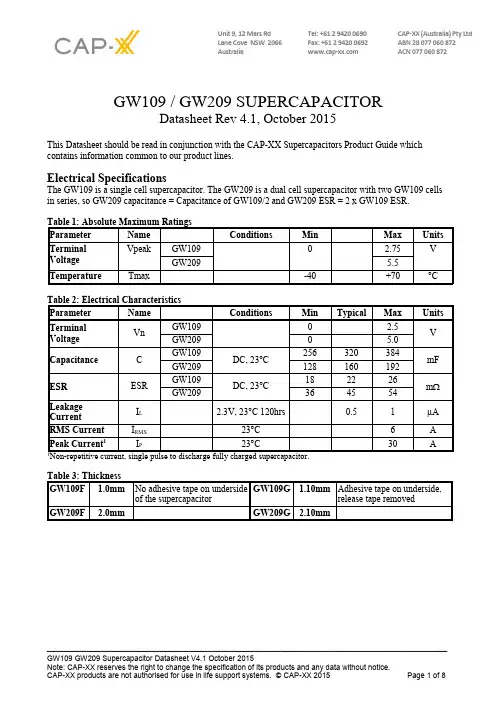
Unit 9, 12 Mars Rd Tel: +61 2 9420 0690 CAP-XX (Australia) Pty LtdLane Cove NSW 2066 Fax: +61 2 9420 0692 ABN 28 077 060 872Australia ACN 077 060 872 GW109 / GW209 SUPERCAPACITORDatasheet Rev 4.1, October 2015This Datasheet should be read in conjunction with the CAP-XX Supercapacitors Product Guide whichcontains information common to our product lines.Electrical SpecificationsThe GW109 is a single cell supercapacitor. The GW209 is a dual cell supercapacitor with two GW109 cellsin series, so GW209 capacitance = Capacitance of GW109/2 and GW209 ESR = 2 x GW109 ESR.Definition of TermsIn its simplest form, the Equivalent Series Resistance (ESR) of a capacitor is the real part of the complex impedance. In the time domain, it can be found by applying a step discharge current to a charged cell as in Fig. 1. In this figure, the supercapacitor is pre-charged and then discharged with a current pulse, I =1A for duration 0.01 secs.Figure 1: Effective capacitance, instantaneous capacitance and ESR for a GW209The ESR is found by dividing the instantaneous voltage step (∆V) by I. In this example = (4.492V-4.447V)/1.03A = 43.7mΩ.The instantaneous capacitance (C i) can be found by taking the inverse of the derivative of the voltage, and multiplying it by I.The effective capacitance for a pulse of duration ∆t n, Ce(∆t n) is found by dividing the total charge removed from the capacitor (∆Q n) by the voltage lost by the capacitor (∆V n). For constant current Ce(∆t n) = I x∆t n/∆V n. Ce increases as the pulse width increases and tends to the DC capacitance value as the pulse width becomes very long (~10 secs). After 2msecs, Fig 1 shows the voltage drop V2ms = (4.447V – 4.414V) =33mV. Therefore Ce(2ms) = 1.03A x 2ms/33mV = 62.4mF. After 10ms, the voltage drop = 4.447 V –4.349V = 98mV. Therefore Ce(10ms) = 1.03A x 10ms/98mV = 105mF. The DC capacitance of a GW209 = 160mF. Note that ∆V, or IR drop, is not included because very little charge is removed from the capacitor during this time. Ce shows the time response of the capacitor and it is useful for predicting circuit behavior in pulsed applications.Measurement of DC CapacitanceFig 2: Measurement of DC Capacitance for a GW209Fig 2 shows the measurement of DC capacitance by drawing a constant 100mA current from a fully charged supercapacitor and measuring the time taken to discharge from 1.5V to 0.5V for a single cell, or from 3V to 1V for a dual cell supercapacitor. In this case, C = 0.1A x 3.406s /2V = 170.3mF, which is well within the 160mF +/- 20% tolerance for a GW209 cell.Measurement of ESRFig 3: Measurement of ESR for a GW209Fig 3 shows DC measurement of ESR by applying a step load current to the supercapacitor and measuring the resulting voltage drop. CAP-XX waits for a delay of 50µs after the step current is applied to ensure the voltage and current have settled. In this case the ESR is measured as 50mV/1.03A = 48.5mΩ.Effective CapacitanceFigure 4: Effective CapacitanceFig 4 shows the effective capacitance for the GW109, GW209 @ 23°C. This shows that for a 1msec PW,you will measure 22.6% of DC capacitance or 63.3mF for a GW109 or 31.6mF for a GW209. At 10msecsyou will measure 60% of the DC capacitance, and at 100msecs you will measure 85% of DC capacitance.Ceffective is a time domain representation of the supercapacitor's frequency response. If, for example, youwere calculating the voltage drop if the supercapacitor was supporting 1A for 10msecs, then you would usethe Ceff(10msecs) = 60% of DC capacitance = 96mF for a GW209, so Vdrop = 1A x ESR + 1A x duration/C= 1A x 45mΩ + 1A x 10ms / 96mF = 149mV. The next section on pulse response shows how the effective capacitance is sufficient for even short pulse widths.Pulse ResponseFig 5 shows that the GW209supercapacitor does an excellent jobsupporting a GPRS class 10 pulsetrain, drawing 1.8A for 1.1ms at25% duty cycle. The source iscurrent limited to 0.6A and thesupercapacitor provides the 1.2Adifference to achieve the peakcurrent. At first glance the freqresponse of Fig 8 indicates thesupercapacacitor would not supporta 1ms pulse, but the Ceff of 31.6mFcoupled with the low ESR supportsthis pulse train with only ~117mVdroop in the supply rail. Fig 5: GW209 Pulse Response with GPRS Class 10 Pulse TrainDC Capacitance variation with temperatureFigure 6: Capacitance change with temperatureFig 6 shows that DC capacitance is approximately constant with temperature.ESR variation with temperatureFigure 7: ESR change with temperatureFig 7 shows that ESR at -40°C is ~2.2 x ESR at room temp, and that ESR at 70ºC is ~0.82 x ESR at room temperature.Frequency ResponseFig 8: Frequency Response of Impedance (biased at 2.3V with a 50mV test signal)Fig 9: Frequency Response of ESR, Capacitance & InductanceFig 8 shows the supercapacitor behaves as an ideal capacitor until approx 10 Hz when the magnitude no longer rolls off proportionally to 1/freq and the phase crosses -45°. Performance of supercapacitors with frequency is complex and the best predictor of performance is Fig 4 showing effective capacitance as a function of pulsewidth.Leakage CurrentFig 10: Leakage CurrentFig 10 shows the leakage current for GW109 at room temperature. The leakage current decays over time and the equilibrium value leakage current will be reached after ~120hrs at room temperature. The typical equilibrium leakage current is 0.5µA at room temperature. At 70°C leakage current will be ~5µA. Charge CurrentFig 11: Charging an GW109 with low currentThe corollary to the slow decay in leakage currents shown in Fig 10 is that charging a supercapacitor at very low currents takes longer than theory predicts. At higher charge currents, the charge rate is as theory predicts. For example, it should take 0.32F x 2.3V / 0.00002A = 10 hrs to charge a 0.16F supercapacitor to 2.3V at20µA, but Fig 11 shows it took 14hrs. At 100µA charging occurs at a rate close to the theoretical rate.RMS CurrentFig 12: Temperature rise in GW209 with RMS currentContinuous current flow into/out of the supercap will cause self heating, which limits the maximum continuous current the supercapacitor can handle. This is measured by a current square wave with 50% duty cycle, charging the supercapacitor to rated voltage at a constant current, and then discharging the supercapacitor to half rated voltage at the same constant current value. For a square wave with 50% duty cycle, the RMS current is the same as the current amplitude. Fig 12 shows the increase in temperature as a function of RMS current. From this, the maximum RMS current in an application can be calculated, for example, if the ambient temperature is 40︒C, and the maximum desired temperature for the supercapacitor is 70︒C, then the maximum RMS current should be limited to 4.5A, which causes a 30︒C temperature increase. CAP-XX Supercapacitors Product GuideRefer to the package drawings in the CAP-XX Supercapacitors Product Guide for detailed information of the product’s dimensions, PCB landing placements, active areas and electrical connections.Refer to the CAP-XX Supercapacitors Product Guide for information on endurance and shelf life, transportation and storage, assembly and soldering, safety and RoHS/EREACH certification.。
WRITTEN CHECKED APPROVEDTo. : DATE : 200 . . .SPECIFICATIONPRODUCT : STARCAPMODEL : DMS seriesKORCHIP CORP.KORCHIP B/D, 817-38, Anyang 2-dong, Manan-gu, Anyang-si, Gyeonggi-do, KOREA TEL : 82 - 31 - 361 - 8000 FAX : 82 - 31 - 361 - 8080Page No.ITEM etc.1Cover Page2Index3 1. Scope2. Part Number System3. Product Model Name4. Photo5. Nominal Specifications4 6. Cell Structure7. Product Construction And Dimension5 8. Packing Specifications6 9. Specifications And Test Method7 10. Measuring Method Of Characteristics8 11. Mounting And Soldering9 12. Cautions For Use10 13. Environmental ManagementIndexItems DMS 3R3 204 R DMS 3R3 224 R Cell SizeØ6.8 × 1.4mm Ø6.8 × 1.4mm OPERATING TEMPERATURE-10 ~ +60 ℃-10 ~ +60 ℃RATED VOLTAGE3.3 VDC 3.3 VDC ELECTROSTATIC CAPACITANCE (F)0.20 F 0.22 F CAPACITANCE TOLERANCE -20 ~ 80 %-20 ~ 80 %EQUIVALENT SERIES RESISTANCE (ESR)LESS THAN 200ΩLESS THAN 200ΩLEAKAGE CURRENT (LC)LESS THAN 150㎂LESS THAN 150㎂1. ScopeThis specification applies to STARCAP(Electric Double Layer Capacitor), submitted to specified customer in cover page.2. Part Number SystemDMS 3R3 204 R (Example)① ② ③ ④① Series Name② Rated Voltage : 3.3VDC③ Capacitance : 0.20 F (204 = 20 × 10+4uF) ④ Terminal Type : R-type3. Product Model Name1) Product : Electric Double Layer Capacitor 2) Model name : DMS3R3204R, DMS3R3224R4. Photo5. Nominal SpecificationsPart Number Dimension (mm)ØD H DMS 3R3 204 R 6.8 Max 1.8 Max DMS 3R3 224 R6.8 Max1.8 Max6. Cell Structure7. Product Construction And DimensionPRODUCTQUANTITY(PCS)SIZE(WxLxH mm)Weight(Kg) Tray Inner Box Outer Box Inner Box Outer BoxDMS 3R3 204 R1001,00016,000180×170×75375×340×350≃ 9 DMS 3R3 224 R1001,00016,000180×170×75375×340×350≃ 9 8. Packing Specification9. Specifications And Test Method10. Measuring Method Of CharacteristicsE0 : VdcR C : 100Ω11. Mounting And SolderingWhen you solder DMS series STARCAP to a printed circuit board, excessive thermalstress could cause the STARCAP's electrical characteristics to deteriorate, compromisethe integrity of the seal or cause the electrolyte to leak due to increased internal pressure.① Recommended condition of mountingIf you want to set or mount DMS series STARCAP on a PCB with resin before soldering for ease of soldering process, follow the thermal condition below.- Hardening Temp. of Resin : 80℃ or below- Hardening Time of Resin : 10 min. or less② Recommended condition of soldering- Soldering Tip Temp. : 350℃ or below- Soldering Time : 3 sec. or less- Times : Three times or less at intervals of 9 sec. or more※ Do not touch the metal case of STARCAP with a soldering iron.③ It is not allowed to go through flow or reflow(IR, Atmosphere heating methodsetc.) process.④ The terminals are plated for good solderability. Rasping terminals may damage the plating layer and degrade the solderability.Do not apply a large force to the terminals. Otherwise, they may break or come off or the STARCAP characteristics may be deteriorated.12. Cautions For UsePlease be careful for following points when you use STARCAP.1) Do not apply more than rated voltage.If you apply more than rated voltage, STARCAP's electrolyte will be electrolyzed and itsESR increase. At the worst, it may be broken.2) Do not use STARCAP for ripple absorption.3) PolarityThe STARCAP is non-polar fundamentally, however STARCAP gets polarity throughaging process before it is packed. Please mount it in accordance with its polarity to maintain the best condition.4) Operating temperature and lifeGenerally, STARCAP has a lower leakage current, longer back-up time and longer life in the low temperature i.e. the room temperature. But it has a higher leakage current, shorter back-up time and shorter life in the high temperature.Please design to keep STARCAP away from calorific parts.5) CleaningSome detergent or high temperature drying causes deterioration of STARCAP.If you wash STARCAP, Consult us.6) Following figure shows the general back-up circuit.D : Diode to prevent the reverse currentR : Resistor to control the chargingcurrentSeries RoHS directivePb, Cr+6, Hg, Cd, PBB,PBDEELV directive Pb, Cr+6, Hg, CdPVC etc.DMSN.D.N.D.N.D.7) Short-circuit STARCAPYou can short-circuit between terminals of STARCAP without resistor. However when you short-circuit frequently, please consult us.8) StorageIn long term storage, please store STARCAP in following condition; ① TEMP. : 15 ~ 35 ℃ ② HUMIDITY : 45 ~ 75 %RH ③ NON-DUST ENVIRONMENT9) Do not disassemble STARCAP. It contains electrolyte. 10) Series connection of STARCAPOver-rated voltage may be applied to a single STARCAP in series connection due to the deviation of capacitance and ESR of each STARCAP. Please inform us if you are using STARCAP in series connection and please design so as not to apply over-rated voltage to each STARCAP, and use STARCAPs from same lot.11) The tips of STARCAP terminals are very sharp. Please handle with care.13. Environmental ManagementAll STARCAP products are RoHS compliant and environment friendly.By changing the solder plating from leaded solder to lead-free solder, our new STARCAP has became even more friendly to the environment.* N.D. : Not detected。
凯迈嘉华(洛阳)新能源有限公司2011 年6 月编写校对审核标检批准会签:警告➢安装本产品之前请认真阅读本说明书;➢产品最好要平放,安装要牢靠、紧固;➢禁止将UCM75V94F模块(以下简称模块)浸入水中;➢禁止将模块放置于热高温源旁,如火、加热器等;➢禁止将模块丢于火或加热器中;➢禁止颠倒正负极使用模块;➢禁止用金属直接连接模块正负极短路;➢禁止将模块与金属,如发夹、项链等一起运输或贮存;➢禁止敲击、抛掷、折弯模块;➢禁止直接焊接模块和用钉子或其它利器穿刺模块。
1产品简介模块是一个完整的能量储存装备,模块主要由32个独立的3000F超级电容单体、外壳、内部连接端子及完整的电压管理电路组成。
可提供75V的耐压和94F的超大容量,具有功率特性好、大电流快速充放电、高低温特性好、免维护、绿色环保等优点。
产品广泛应用在在运输、汽车、工业、UPS、电信等领域。
模块间可以串联起来获得更高的工作电压,可以并联起来获得更高的能量存储,也可以通过串、并联结合的方法获得更高的工作电压和能量存储。
模块外壳是由上下两块绝缘且强度高的聚甲醛板、铝板等连接而成,连接处均涂有玻璃胶,该外壳密封可靠、防水性能好。
电压管理电路有两个开路集电极逻辑输出口,可以及时反映出模块中任意单体是否处于过压状态,保护每个单体在过压时进行电压均衡,此外,该电路中还有两个温度监控端口,并提供NTC热敏电阻供用户检测模块温度时使用。
2主要特征表1模块的主要外形特征3主要技术参数4使用条件4.1贮存温度-40℃~+70℃;4.2工作温度-40℃~+65℃;4.3相对湿度湿度≤80%(+25℃);5打开包装在拆箱前,先检查装载货物的木箱是否完好。
任何损坏(包括木箱破损和货物损坏)都要及时向送货方反映。
从木箱中取出货物,保留包装物,直到货物检查完毕并确保能正常运行后方能丢弃(注意:原始包装材料符合空运和陆运要求)。
取出货物时,请勿直接握住模块两极,而应握住模块主体,轻轻从木箱中取出。
HCCCAP EDLCsSPECIFICATION HCCCAP超级电容规格书【PRODUCT】产品:HCCCAP EDLCs【MODEL】型号:HCAP-C2R7166北京合众汇能科技有限公司HCC ENERGY TECH.Co.,LTD.TEL:+86-10-82897371email:*******************1.适用范围Scope本产品规格书对产品的性能,测试方法进行了规范,作为技术确认的参照。
数据参数仅作参考,不同批次与不同时间生产的实际产品参数可能会有所变化,以实际收到的产品为准,确切参数请及时向厂家核实。
This specification describes,the product property and test method,and should serve as the reference for technical assurance.These data is only for reference,actual product data in different batches and different times may vary,with the actual receipt of the product as a prospective,exact parameters,please promptly to the manufacturers to verify.2.一般特性General Specifications1)产品性能Features●高能量密度Ultra High Energy Density●长寿命Long Usage Life●高低温性能Excellent Performance at High and Low Temperatures●环保Environmental Friendly●免维护Maintenance Free2)产品应用范围Typical Applications●智能电网及其它配套设备Smart grid and other ancillary equipment●智能三表Intelligent Three-ammeters●集中器Concentrator●故障指示器Fault Indicator●混合动力汽车HEV/EV●太阳能/风能Solar/Wind energy●电机启动Motor drive●后备电源Memory Back up Batteries3)标准测试条件在标准大气压,温度5~35℃,相对湿度小于85%条件下进行测试;本规格书标准测试条件为标准大气压,温度25℃,相对湿度小于60%。
XTM-18 Supercapacitor18 V, 61.7 F ModuleDescriptionEaton supercapacitors are high reliability, high power, ultra-high capacitance energy storage devices utilizing electric double layer capacitor (EDLC) construction combined with proprietary materials and processes. This combination of advanced technologies allows Eaton to offer a wide variety of capacitor solutions tailored to applications for backup power, pulse power and hybrid power systems.They can be applied as the sole energy storage or in combination with batteries to optimize cost, life time and run time. System requirements can range from a few microwatts to megawatts.All products feature low ESR for high power density with environmentally friendly materials for a green power solution. Eaton supercapacitors are maintenance-free with design lifetimes up to 20 years* and operating temperatures down to -40 °C and up to +85 °C.Features and benefits• Long life energy storage, up to 20 years*• Very low Equivalent Series Resistance (ESR)• Wide operating temperature range•Cost effective backup power and large energyrecapture•High efficiency (> 98%) under broad operating conditions• High reliability, green solution•Low operating costs and maintenance freeApplications•Industrial computer and emergency backup energy•Battery assist engine starting for cold or frequent starts• Soft shutdown for industrial robotics and PLCs •Automated guided vehicles and warehouse automationHALOGENHF FREE*Supercapacitor lifetimes vary based on charge voltage and temperature. See Eaton’s application guidelines or contact your local Eaton sales representative for more information on lifetime estimates2Technical Data 10941Effective September 2019XTM-18 Supercapacitor18 V, 61.7 F Module/electronicsRatingsCapacitance61.7 F Maximum working voltage 18.0 V Surge voltage19.8 VCapacitance tolerance-5% to +20%Operating temperature range-40 °C to +65 °C (with linear voltage derating to 15 V @ +85 °C)SpecificationsCapacitance 1 (F)Part numberMaximum working voltage (V)Maximum initial ESR 1 (mΩ)Leakage current 1,2 (mA)Stored energy 3 (Wh)Peak Power 5 (kW)Pulsecurrent 4 (A)Continuouscurrent 6 (A)Typical thermal resistance 8 Rth (°C/W)61.7XTM-18R0626-R 18.02226 2.8 3.7235.620 1.5PerformanceParameterCapacitance Change (% of initial value)ESR(% of initial maximum value)Lifetime: (1500 hours at maximum temperature and voltage)≤ 30%≤ 200%Charge/Discharge Cycles 7 (500,000 at +20 °C)≤ 20%≤ 200%Storage: (3 years, uncharged, < +35 °C)≤ 5%≤ 10%1.Capacitance, Equivalent Series Resistance (ESR) and Leakage current are measured according to IEC62391-1 with current in milliamps (mA) = 8 x C x V.2. Leakage current at +20 °C after 72 hour charge and hold at rated voltage.3. Stored Energy (Wh) = 0.5 x C x V 236004. Pulse current for 1 second from full rate voltage to half voltage. (A) = 0.5 x V x C (1 + ESR x C)5. Peak Power (W) = V 24 x ESR6. Continuous current with a 15 °C temperature rise.7. Cycling between rated voltage and half voltage, 3 second rest at +20 °C.8. Thermal resistance (Rth) cell body temperature to ambient in open air in degrees C per Watt (°C/W)Safety and CertificationsAgency information UL810a (cells)Shock and vibration IEC 60068-2-6, IEC 60068-2-27, IEC 60068-2-29 (cells)Environmental RoHS, Halogen Free, IP54Warnings Do not overvoltage, do not reverse polarity ShippingNo restrictions per UN3499EatonElectronics Division 1000 Eaton Boulevard Cleveland, OH 44122United States/electronics© 2019 EatonAll Rights Reserved Printed in USAPublication No. 10941 BU-MC19071September 2019Technical Data 10941Effective September 2019XTM-18 Supercapacitor 18 V, 61.7 F Module Life Support Policy: Eaton does not authorize the use of any of its products for use in life support devices or systems without the express writtenapproval of an officer of the Company. Life support systems are devices which support or sustain life, and whose failure to perform, when properly used in accordance with instructions for use provided in the labeling, can be reasonably expected to result in significant injury to the user.Eaton reserves the right, without notice, to change design or construction of any products and to discontinue or limit distribution of any products. Eaton also reserves the right to change or update, without notice, any technical information contained in this bulletin.Eaton is a registered trademark.All other trademarks are property of their respective owners.Follow us on social media to get thelatest product and support information.Dimensions (mm)Part marking• Manufacturer • Capacitance (F)• Module operating voltage (V) •Family code or part numberPart numbering systemXTM–18R0626-RFamily code Voltage (V) R = decimal Capacitance (μF)valueMultiplierStandard productXTM=Family code18R0 = 18.0 VExample 626 = 61.7 x 10⁶μF or 62 FPackaging information•Standard packaging: Bulk, 1 part per box, 10 boxes per cartonT ypical mass: 0.75 kg。