
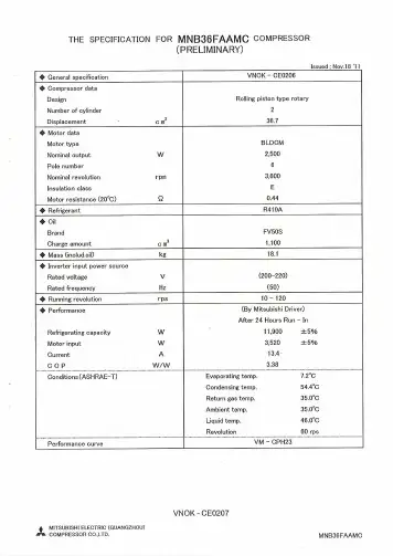
MNB36FAAMC(单相)
- 格式:pdf
- 大小:6.06 MB
- 文档页数:29

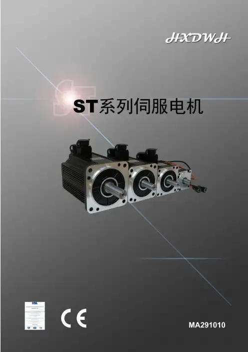
LB系列机座号(mm):80、110、130、150额定转矩(Nm):1.3~27额定功率(Kw):0.4~5.5额定转速(rpm):1500、2000、2500、3000最高转速(rpm):/转子惯量:中惯量标配反馈元件:增量式编码器(2500C/T)失电制动器:可配适配驱动器工作电压(VAC):220LBB系列机座号(mm):80、110、130、150额定转矩(Nm):1.3~19.1额定功率(Kw):0.4~3.0额定转速(rpm):1500、2000、3000最高转速(rpm):3000、5000转子惯量:中惯量标配反馈元件:总线式光电编码器失电制动器:可配适配驱动器工作电压(VAC):220HB系列机座号(mm):110、130、150额定转矩(Nm):2~27额定功率(Kw):0.6~5.5额定转速(rpm):1500、2000、2500、3000最高转速(rpm):/转子惯量:中惯量标配反馈元件:增量式编码器(2500C/T)失电制动器:可配适配驱动器工作电压(VAC):380HBB系列机座号(mm):110、130、150额定转矩(Nm):2.4~28.7额定功率(Kw):0.4~5.5额定转速(rpm):1500、2000最高转速(rpm):3000转子惯量:中惯量标配反馈元件:总线式光电编码器失电制动器:可配适配驱动器工作电压(VAC):380请您关注以下伺服电机为自冷式散热方式,安装时请选择足够大的安装板。
伺服电机长期工作,机体本身会有一定的温度,这是正常情况。
装配了失电制动器的伺服电机,其失电制动器的电源必须由驱动器控制开闭,否则会造成工作状态不佳。
伺服电机内装精密反馈元件,严禁重力敲击电机轴伸端及后部。
请注意电机轴伸端的最大径、轴向力的限值。
严禁随意更改、拆装及加工电机部件。
请您将需求告之我们,我们来为您服务。
电机电联接器转矩转速曲线示意图LB 、HB系列 LBB 、HBB 系列LB、LBB 、HB 、HBB 系列伺服电机的Mmax=3Mn ;Mmax 输出状态为短时工作。

G 6BHigh Capacity and HighDielectric Strength M iniature Relay with Fully Sealed Construction in 5 A (8 A) SPST-NO (1a), SPST-NC (1b), DPST-NO (2a),DPST-NC (2b) Types•High sensitive with operating power of 98 mW.(G6B-1114P-US and G6B-1174P-US models)•High insulation with dielectric strength of 3,000VAC between coil and contacts (impulse withstand voltage of 6 kV).•Stick packing models are provided in consideration of compatibility to the automatic production line.•Standard model conforms to UL/CSA standards. Other SEV approved models are also available.•AgSnIn contacts suitable for loads that generate surge voltage such as inductive load and capacity load etc. are available for the whole product line.•Ultrasonically cleanable models is available.•Operation indicator & surge absorption diode are built-in for the whole product line.•Double-pole type is available for the whole product line.■Model Number LegendRoHS Compliant■Application Examples•Ideal for output applications of control equipmentsG6B-@-@@@@@-@-@-@-@-@———————————12345678910111.Relay FunctionNone: Single-side stableU : Single-winding latching(G6B @-1114 models only)K : Double-winding latching(G6B @-1114 models only)2.Number of poles 1: 1-pole 2: 2-pole3.Contact Form 1: SPST -NO (1a)1: SPST -NO (1a)+SPST -NC (1b)2: DPST -NO (2a)0: DPST -NC (2b)4.Classification 1: Standard7: High-capacity 5.Enclosure rating 4: Fully sealed 7: Flux protection6.Terminal Shape P: PCB terminalsSocket mounting terminals7.Contact materialNone: Standard (Ag-alloy (Cd free))FD : AgSnIn contact(Suitable for DC inductive load with high inrush current)8.Operation Indicator DiodeAvailability None: StandardND : Operation indicator & coil surgeabsorption diode (for -1177 type only)9.Approved Standards US: UL/CSA10.Washability None: StandardU : For ultrasonically cleanable 11.MountingNone: Mounted directly to PCB P6B : Mounted to SocketG6B PCB Power RelayG 6 B ■Ordering Information●Standard Models (UL, CSA certified)Note:AgSnIn contact models are highly welding-resistant, and roughening of contacts due to inrush current and inductive load is lessened.●Models for Ultrasonically CleanableNote:When ordering, add the rated coil voltage to the model number.Example: G6B-1114P-US 5 VDC●Connecting Sockets (Sold Separately)Note 1.When using by combining sockets of the G6B-1174P-US and P6B-04P models, the rated current will be5A due to its rated switching current.e the G6B-@@@@P(-FD)-US P6B to mount to a P6B Socket.3.The hold-down clips of the P6B-C2 model are not suitable for the G6B-1174P and G6B-1177P modelssince they have different heights.4.Products with UL/CSA certification marks will be supplied for orders of standard models.Numberof polesContact material Standard (Ag-alloy (Cd free))AgSnIn contact Minimumpacking unit Relay Function Contact form Model Rated coil voltage Model Rated coil voltage1-poleSingle-side stableSPST-NO (1a)(Standard)G6B-1114P-US5, 6, 12, 24 VDC G6B-1114P-FD-US5, 6, 12, 24 VDC100pcs/tray SPST-NO (1a)(High-capacity)G6B-1174P-US5, 6, 12, 24 VDC G6B-1174P-FD-US5, 6, 12, 24 VDC20pcs/tube Single-windinglatchingSPST-NO (1a)(Standard)G6BU-1114P-US5, 6, 12, 24 VDC G6BU-1114P-FD-US5, 12, 24 VDC100pcs/tray Double-windinglatchingSPST-NO (1a)(Standard)G6BK-1114P-US5, 6, 12 VDCG6BK-1114P-FD-US5, 6, 12 VDC24 VDC24 VDCSingle-side stableSPST-NO (1a)(Built-in high-capacityoperation indicator &diode)G6B-1177P-ND-US5, 12, 24 VDC G6B-1177P-FD-ND-US5, 12, 24 VDC20pcs/tube2-pole Single-side stableSPST-NO (1a)+SPST-NC (1b) (Standard)G6B-2114P-US5, 6, 12, 24 VDC G6B-2114P-FD-US5, 6, 12, 24 VDC100pcs/tray DPST-NO (2a)(Standard)G6B-2214P-US5, 6, 12, 24 VDC G6B-2214P-FD-US5, 6, 12, 24 VDCDPST-NC (2b)(Standard)G6B-2014P-US5, 6, 12, 24 VDC G6B-2014P-FD-U5, 6, 12, 24 VDCNumberof polesContact material Standard (Ag-alloy (CD free))AgSnIn contact Minimumpacking unit Relay Function Contact form Model Rated coil voltage Model Rated coil voltage1-poleSingle-side stableSPST-NO (1a)(Standard)G6B-1114P-US-U5, 6, 12, 24 VDC G6B-1114P-FD-US-U6, 12, 24 VDC100pcs/tray Single-windinglatchingSPST-NO (1a)(Standard)G6BU-1114P-US-U24 VDC−−Double-windinglatchingSPST-NO (1a)(Standard)G6BK-1114P-US-U5, 6, 12, 24 VDC G6BK-1114P-FD-US-U12, 24 VDC2-pole Single-side stableSPST-NO (1a)+SPST-NC (1b) (Standard)G6B-2114P-US-U5, 12, 24 VDC G6B-2114P-FD-US-U5, 12, 24 VDCDPST-NO (2a)(Standard)G6B-2214P-US-U5, 6, 12, 24 VDC G6B-2214P-FD-US-U5, 12, 24 VDCDPST-NC (2b)(Standard)G6B-2014P-US-U5, 12, 24 VDC G6B-2014P-FD-US-U5, 12, 24 VDCApplicable relay Model Minimum ordering unitG6B-1114P(-FD)-US-P6BG6B-1174P(-FD)-US-P6BG6B-1177P(-FD)-ND-US-P6BG6BU-1114P-US-P6BP6B-04P20 pcsG6BK-1114P-US-P6B P6B-06PG6B-2114P-US-P6BG6B-2214P-US-P6BG6B-2014P-US-P6BP6B-26PRemoval Tool P6B-Y11 pcsHold-down Clips P6B-C2Rated coil voltageG6BPCB Power RelayG 6B■Ratings●Coil: 1-Pole, Single-side Stable Type (Including models for ultrasonically cleanable)●Coil: 2-Pole, Single-side Stable Type (Including models for ultrasonically cleanable)●Coil: Single-winding Latching Type (Including models for ultrasonically cleanable)●Coil: Double-winding Latching Type (Including models for ultrasonically cleanable)●Coil: Operation Indicator Model (Flux-resistant type. Do not wash down with water.)Note 1.The rated current and coil resistance are measured at a coil temperature of 23°C with a tolerance of ±10%.2.The operating characteristics are measured at a coil temperature of 23°C.3.The “Max. voltage” is the maximum voltage that can be applied to the relay coil.●ContactsNote 1.The values in the parentheses ( ) are for -FD models only.e the -FD type for inductive load and switching load which contact roughening is small.ItemRated voltageRated current (mA)Coil resistance(Ω)Must operate voltage (V)Must release voltage (V)Max. voltage(V)Power consumption (mW)% of rated voltage5 VDC 4012570% max.10% min.160%(at 23°C)Approx. 2006 VDC 33.318012 VDC 16.772024 VDC8.32,880ItemRated voltageRated current (mA)Coil resistance(Ω)Must operate voltage (V)Must release voltage (V)Max. voltage(V)Power consumption (mW)% of rated voltage5 VDC 6083.380% max.10% min.140%(at 23°C)Approx. 3006 VDC 5012012 VDC 2548024 VDC12.51,920ItemRated voltageRated current (mA)Coil resistance(Ω)Must set voltage (V)Must reset voltage (V)Max. voltage (V)Power consumption % of rated voltageSet coil(mW)Reset coil (mW)5 VDC 4012570% max.70% max.160% (at 23°C)2002006 VDC 33.318012 VDC 16.772024 VDC8.32,880ItemRated voltageRated current (mA)Coil resistance (Ω)Must set voltage (V)Must reset voltage (V)Max. voltage(V)Power consumption Set coil Reset coil Set coil Reset coil% of rated voltageSet coil(mW)Reset coil (mW)5 VDC 565689.289.270% max.70% max.130% (at 23°C)2802806 VDC 46.846.8128.5128.512 VDC 23.323.351551524 VDC11.711.72,0602,060ItemRated voltageRated current (mA)Coil resistance(Ω)Must operate voltage (V)Must release voltage (V)Max. voltage(V)Power consumption (mW)% of rated voltage5 VDC 4311670% max.10% min.130% (at 23°C)Approx. 20012 VDC 19.7610Approx. 24024 VDC11.32,120Approx. 275ModelG6B-1114P-US G6BU-1114P-US G6BK-1114P-US G6B-1114P-FD-US G6BU-1114P-FD-US G6BK-1114P-FD-USG6B-1174P-US G6B-1177P-ND-US G6B-1174P-FD-US G6B-1177P-FD-ND-US G6B-2114P-US G6B-2214P-US G6B-2014P-US G6B-2114P-FD-US G6B-2214P-FD-US G6B-2014P-FD-USLoadItem Resistive loadInductive load (cos φ = 0.4; L/R = 7 ms)Resistive loadInductive load (cos φ = 0.4; L/R = 7 ms)Resistive loadInductive load (cos φ = 0.4; L/R = 7 ms)Contact type Single Contact material Ag-Alloy (Cd free)Rated load 5 A (3 A) at 250 VAC 5 A (3 A) at 30 VDC2 A (2 A) at 250 VAC 2 A (2 A) at 30 VDC8 A (5 A) at 250 VAC 8 A (5 A) at 30 VDC2 A (2 A) at 250 VAC 2 A (2 A) at 30 VDC5 A (3 A) at 250 VAC 5 A (3 A) at 30 VDC1.5 A (1.5 A) at 250 VAC 1.5 A (1.5 A) at 30 VDCRated carry current 5 A (5 A)8 A (5 A) 5 A (5 A)Max. switching voltage 380 VAC, 125 VDCMax. switching current5 A (5 A)8 A (5 A)5 A (5 A)G6BPCB Power RelayG 6B■CharacteristicsNote 1.The values here are initial values.2.The G6B-1177P(-FD)-ND model is flux-resistant. Do not wash it down with water. *1.The contact resistance was measured with 1 A at 5 VDC using a voltage-drop method.*2.Measurement conditions: The insulation resistance was measured with a 500 VDC megohmmeter at the same locations as the dielectric strength wasmeasured.(Except the location between set/reset coil)*3.This value was measured at a switching frequency of 120 operations/min.ModelG6B-1114P-US G6B-1114P-FD-USG6B-1174P-US G6B-1174P-FD-USG6BU-1114P-US G6BK-1114P-USG6B-1177P(-FD)-ND-US G6B-2114P-US G6B-2114P-FD-US G6B-2214P-US G6B-2214P-FD-USG6B-2014P-US G6B-2014P-FD-USItemClassification Single-side stableSingle-windinglatching Double-windinglatchingBuilt-in operation indicator & surge absorption diodeSingle-side stable Contact resistance *130 m Ω max.Operate (set) time 10 ms max.Release (reset) time 10 ms max.Min. set pulse width −15 ms (at 23°C)−Min. reset pulse width −15 ms (at 23°C)−Insulation resistance *21,000 M Ω min.Dielectric strengthBetween coil and contacts3,000 VAC, 50/60 Hz for 1 min2,000 VAC,50/60 Hz for 1 min3,000 VAC, 50/60 Hz for 1 minBetween contacts of the same polarity1,000 VAC, 50/60 Hz for 1 minBetween contacts of different polarity−2,000 VAC, 50/60 Hz for 1 minBetween set and reset coils−250 VAC,50/60 Hz for 1 min−Impulse withstand voltage (between coil and contacts)6 kV 1.2 × 50 μs 4.5 kV 1.2 × 50 μs 6 kV 1.2 × 50 μsVibrationresistance Destruction 10 to 55 to 10 Hz, 0.75 mm single amplitude (1.5 mm double amplitude)Malfunction10 to 55 to 10 Hz, 0.75 mm single amplitude (1.5 mm double amplitude)Shock resistanceDestruction1,000 m/s 2Malfunction 100 m/s 2300 m/s 2100 m/s 2DurabilityMechanical50,000,000 operations min. (at 18,000 operations/hr)Electrical100,000 operation min. (at 1,800 operations/hr under rated load)Failure rate (P level) (reference value) *310 mA at 5 VDCAmbient operating temperature -25°C to 70°C (with no icing or condensation)Ambient operating humidity 5% to 85%WeightApprox. 3.5 to 4.6 g Approx. 3.5 g Approx. 3.7 g Approx. 5.4 g Approx. 4.5 gG6BPCB Power RelayG 6B■Engineering Data●Maximum Switching Current G6B-1114P-US G6B-1174P-FD-USG6B-1174P-USG6B-2114P-US G6B-2214P-US G6B-2014P-US●Durability●Ambient Temperature vs. Maximum Coil VoltageG6B-1114P-US G6B-1174P-US G6B-1174P-FD-USG6B-2114P(-FD)-US G6B-2214P(-FD)-US G6B-2014P(-FD)-USG6B-1114P-USG6B-1174P-USG6B-1174P-FD-USG6B-2114P-US G6B-2214P-US G6B-2014P-US Note:The maximum coil voltage refers to the maxi-mum value in a varying range of operating power voltage, not a continuous voltage.●Ambient Temperature vs. Must Operate and Must Release Voltage G6B-1114P-US●Mutual Magnetic Interference G6B-1114P-USG6B-1114P-USS w i t c h i n g c u r r e n t (A )Switching voltage (V)S w i t c h i n g c u r r e n t (A )Switching voltage (V)S w i t c h i n g c u r r e n t (A )Switching voltage (V)D u r a b i l i t y (x 10 o p e r a t i o n s )Switching current (A)D u r a b i l i t y (x 10 o p e r a t i o n s )Switching current (A)M a x i m u m c o i l v o l t a g e (%)Ambient temperature (°C)8Am b ient temper a t u re (°C)M u s t -o p e r a t e /m us t -r e l e a s e v o l t a g e (%)−+1.0+0.50−0.5−1.0Average valueTestInitial stage+1.0+0.50−0.5−1.0Average valueTestInitial stageMust operate voltage Must release voltage C h a n g e r a t e o n t h e b a s i s o f i n i ti a l v a l u e (%)C h a n g e r a t e o n t h e b a s i s o f i n i t i a l v a l u e (%)+1.0+0.50−0.5−1.0Aver a ge v a l u eTe s tIniti a l s t a ge +1.0+0.50−0.5−1.0Aver a ge v a l u eTe s tIniti a l s t a geM us t oper a te volt a ge M us t rele as e volt a geSa Sa C h a n g e r a t e o n t h e b a s i s o f i n i t i a l v a l u e (%)C h a n g e r a t e o n t h eb a s i s o f i n i t i a l v a l u e (%)G6BPCB Power RelayG6B■Dimensions●Shock Malfunction●Hot Starts 2YZSa mple: G6B-1114P-U S N u m b er of Rel a y s : 12 pc sTe s t Condition s : S hock i s a pplied in ±X, ±Y , a nd ±Z direction s three time s e a ch with witho u t energizing the Rel a y s to check the n u m b er of m a lf u nction s .Re qu irement: Nonem a lf u ction 100 m/s22YZSample: G6B-1174P-US G6B-1174P-FD-USTest Conditions: Shock is applied in ±X, ±Y, and ±Z directions three times each with without energizing the Relays to check the number of malfunctions.Requirement: Nonemalfuction 100 m/s 2YZSa mple: G6BK-1114P-U S N u m b er of Rel a y s : 12 pc sTe s t Condition s : The v a l u e a t whichm a lf u nction occ u rred w as me asu red a fter a pplying s hock to the te s t piece 3 time s e a ch in 6 direction s a long 3a xe s .S t a nd a rd v a l u e: 300 m/s 2Am b ient temper a t u re (°C)−R a t eo f v a r i a b i l i t y (%)3−−R a t e o f v a r i a b i l i t y (%)Ambient temperature (°C)−−−R a t e o f v a r i a b i l i t y (%)Ambient temperature (°C)−−−(1.2)Note: Orientation marks are indicated as follows:* Average value Note: Check carefully the coil polarity of the Relay.1-pole Single-side Stable ModelsG6B-1114P(-FD)-USPCB Mounting Holes (BOTTOM VIEW)Tolerance: ±0.1 mmTerminal Arrangement/ Internal Connections(BOTTOM VIEW)Note: Orientation marks are indicated as follows:(1.2)* Average value Note: Check carefully the coil polarity of the Relay.1-pole Single-side Stable Models G6B-1174P(-FD)-USPCB Mounting Holes (BOTTOM VIEW)Tolerance: ±0.1 mmTerminal Arrangement/ Internal Connections (BOTTOM VIEW)G6BPCB Power RelayG 6B* Average valueNote: Orientation marks are indicated as follows:Note: Check carefully the coil polarity of the Relay. S: Set coil R: Reset coil1-pole Single-winding Latching Model G6BU-1114P-USPCB Mounting Holes (BOTTOM VIEW)Tolerance: ±0.1 mmTerminal Arrangement/ Internal Connections(BOTTOM VIEW)* Average valueNote: Orientation marks are indicated as follows:Note: Check carefully the coil polarity of the Relay. S: Set coil R: Reset coil1-pole Double-winding Latching Model G6BK-1114P-USPCB Mounting Holes (BOTTOM VIEW)Tolerance: ±0.1 mmTerminal Arrangement/ Internal Connections(BOTTOM VIEW)* Average valueNote: Check carefully the coil polarity of the Relay.Note: The G6B-1177P-ND-US model has aflux-resistant construction. Do not wash it down with water. Pay attention to the polarity of the coil since the LED and surge absorption diode are built-in.1-pole Single-side stable Models SPST-NO (1a) (Built-in high capacity operation indicator & surge absorption diode)G6B-1177P(-FD)-ND-US PCB Mounting Holes (BOTTOM VIEW)Tolerance: ±0.1 mm Terminal Arrangement/ Internal Connections(BOTTOM VIEW)* Average valueNote: Check carefully the coil polarity of the Relay.G6B-2114P-US2-poles Single-side stable Models (SPST -NO (1a) + SPST-NC (1b),DPST-NC (2c), SPST-NO(1a))G6B-2114P-US G6B-2214P-US G6B-2014P-USPCB Mounting Holes(BOTTOM VIEW)Tolerance: ±0.1 mmTerminal Arrangement/ Internal Connections (BOTTOM VIEW)G6B PCB Power RelayG 6 B ■Connecting SocketsDimensions* Average valueSocket for 1-pole Single-winding Latching Model andSingle-side Stable ModelP6B-04PPCB Mounting Holes(BOTTOM VIEW)Tolerance: ±0.1 mm* Average valueSocket for 1-pole Double-winding Latching ModelP6B-06P PCB Mounting Holes(BOTTOM VIEW)Tolerance: ±0.1 mm* Average valueDouble-ocket/Double-pole Single-side StableP6B-26PPCB Mounting Holes(BOTTOM VIEW)Tolerance: ±0.1 mm■Removal ToolP6B-Y1■Hold-down ClipsP6B-C2■Related ProductsThe G6B-4 Terminal Relay series with4-point output is also available.For details, contact your OMRON salesrepresentative.G6BPCB Power RelayG 6B■Approved Standards•The approval rating values for overseas standards are different from the performance values determined individually. Confirm the values before use.UL Recognized: (File No. E41643)CSA Certified:(File No. LR31928)EN/IEC, TÜV Certified: (Registration No. R50158246)ModelContactformCoil ratingsContact ratingsNumber of test operationsG6B-1114P-US G6B-1114P-FD-US13 to 24 VDC5 A, 250 VAC (General Use) at 80°C6,0005A, 30 VDC at 80°C 1/8HP, 250 VAC at 80°C 1,0001/6HP, 250 VAC at 80°CG6B-1174P-US G6B-1174P-FD-US 13 to 24 VDC 8 A, 250 VAC (General Use) at 80°C 6,0008 A, 30 VDC at 80°CG6B-2114P(-FD)-US G6B-2214P(-FD)-US G6B-2014P(-FD)-US23 to 48 VDC5 A, 250 VAC (General Use) at 40°C 5 A, 30 VDC at 40°CModelContact formCoil ratingsContact ratingsNumber of test operationsG6B-1114P-US G6B-1114P-FD-US13 to 24 VDC5 A, 250 VAC (General Use) at 80°C6,0005A, 30 VDC at 80°C 1/6HP, 250 VAC at 80°C1,000360WT, 120 VAC at tungsten 80°CG6B-1174P-US G6B-1174P-FD-US 13 to 24 VDC 8 A, 250 VAC (General Use) at 80°C 6,0008 A, 30 VDC at 80°CG6B-2114P(-FD)-US G6B-2214P(-FD)-US G6B-2014P(-FD)-US23 to 48 VDC5 A, 250 VAC (General Use) at 40°C 5 A, 30 VDC at 40°CModelContact formCoil ratings Contact ratingsNumber of test operationsG6B-1114P-US13 to 48 VDC5 A, 250 VAC (cos φ = 1) at 70°C20,000 2 A, 250 VAC (cos φ = 0.4) at 70°C 5 A, 30 VDC (L/R = 0 ms) at 70°C G6B-1174P-US13 to 48 VDC8 A, 250 VAC (cos φ = 1) at 70°C2 A, 250 VAC (cos φ = 0.4) at 70°C 8 A, 30 VDC (L/R = 0 ms) at 70°CG6B-2114P-US G6B-2214P-US G6B-2014P-US23 to 48 VDC5 A, 250 VAC (cos φ = 1) at 70°C1.5 A, 250 VAC (cos φ = 0.4) at 70°C 5 A, 30 VDC (L/R = 0 ms) at 70°CG6B PCB Power RelayG 6 B ■Precautions●Please refer to “PCB Relays Common Precautions” for correct use.●Mounting•When installing more than two Relaysside by side on a PCB, keep the gapsas shown below.It may cause a malfunction if heat isnot dissipated smoothly from theRelay.•No specified mounting direction.●Mounting Height of Sockets andPrecautions•Hold-down clips (for mounting andremoval) are also available.(For P6B-C2 model) However, it is not suitablefor G6B-1174P and G6B-1177Pmodels.•Removal tool is also available.(For P6B-Y1 model) However, it is notsuitable for G6B-1177P model.●Inhibit Circuit of theG6B-1177P(-FD)-ND-US Model•Do not use under conditions in which asurge is included in the power supply,such as when an inductive load isconnected in parallel to the coil. Doingso will cause damage to the installed(or built-in) coil surge absorbing diode.●Using SPDT contact of theSPST-NO+SPST-NC Relay•Do not construct a circuit so thatovercurrent and burning occur if theNO, NC and SPDT contacts areshort-circuited with theSPST-NO+SPST-NC Relay.Arcingmay generate short-circuiting betweencontacts if there is short-circuitingbecause of conversion to the MBBcontact caused by asynchronousoperation of the NO and NC contacts,the interval between the NO and NCcontacts is small, or a large current isleft open.●Other precautions•The P6B model has a flux-resistantconstruction. Do not wash it down withwater.•Perform wiring of No.1 and No. 2 of theX terminal as COM for double-windinglatching as shown below. Theoperation stability improves by doingthis.•Check carefully the coil polarity (+ and-)of the Relay G6B-1177P(-FD)-ND-US.Do not reverse the polarity whenconnecting. Otherwise the built-in coilsurge absorption diode may bedamaged.•This Relay is a Power Relay which issuitable for power load switching. Donot use the G6B for signal purposessuch as micro load switching under100 mA.Correct Usebetween terminalsPitch:2.54 mm ×* 19.5 mm max. forG6B-1174P-FD-US,G6B-1174P-US modelsand 22 mm max. forG6B-1177P-FD-ND-US,G6B-1177P-ND-USmodels.• Applic a tion ex a mple s provided in thi s doc u ment a re for reference only. In a ct ua l a pplic a tion s, confirm e qu ipment f u nction s a nd sa fety b efore us ing the prod u ct.• Con su lt yo u r OMRON repre s ent a tive b efore us ing the prod u ct u nder condition s which a re not de s cri b ed in the m a n ua l or a pplying the prod u ct to n u cle a r control s y s tem s, r a ilro a d s y s tem s, a vi a tion s y s tem s, vehicle s, com bus tion s y s tem s, medic a l e qu ipment, a m us ement m a chine s, sa fety e qu ipment, a nd other s y s tem s or e qu ipment th a t m a y h a ve a s erio us infl u ence on live s a nd property if us ed improperly. M a ke su re th a t the r a ting s a nd perform a nce ch a r a cteri s tic s of the prod u ct provide a m a rgin of sa fety for the s y s tem ore qu ipment, a nd b e su re to provide the s y s tem or e qu ipment with do ub le sa fety mech a ni s m s.OMRON CorporationElectronic and Mechanical Component s Company Contact: /ecb Cat. No. K021-E1-080812(0207)(O)Note: Do not u s e thi s document to operate the Unit.。

特点高精度,支持50Hz/60Hz IEC521/1036标准的精度要求,在500:1的动态范围内平均误差小于0.3%,信号跳动小于0.3%校表过程中高稳定性,输出频率波动小于0.1% 精确测量正、负两个方向的有功功率,且以同一方向计算电能有两个电流采样端,分别采样火线和零线电流,取两个电流采样端中的较大值作为计量,即使在错误用电时电流通道增益可变,在电流通道输入端可以使用小的分流电阻慢速输出脉冲能直接驱动电机工作,快速输出脉冲可用于计算机数据处理防窃电功能,逻辑输出脚REVP 、FAULT 用于显示反向用电或者错误用电状况芯片上有电压检测电路,检测掉电状况 具有防潜动功能芯片上带参考电压源2.44V ±8%(温度系数典型值30ppm/℃),也可以使用外部电压源 单工作电源5V低功耗15mW (典型值)相关专利申请中概述BL6501A 集成电路是电子电度表的核心芯片,基于此芯片设计的电子电度表具有外围电路简单、精度高、稳定性好等特点,适用于单相两线电力用户的电能计量。
利用BL6501A 可以制成单相反窃电功能的电子电度表,这种电度表以同一方向计量计算正向或负向的有功功率,累计用电量。
BL6501A 具有两个电流采样端,分别采样火线和零线电流,当电流误差超过12.5%时,表明有窃电行为或错误接线,Pin19(FAULT )发出指示信号,并按照两个电流中大的一个电流值计量。
BL6501A 基于数字信号处理,有测量负向有功功率的功能。
它能把负向有功功率转换成与正向有功功率方向一致的脉冲输出。
Pin22(CF )输出较高频率的脉冲,用于计量和计算机数据处理,Pin23(F1)和Pin24(F2)输出较低频率的脉冲用于驱动脉冲电机,间接驱动机械字轮计度器,记录用电量。
在测量负向功率时Pin20(REVP )有负电平输出,用于指示该时的功率为负方向。
BL6501A 着重考虑了校表过程中读数误差的稳定性的需求,成品测量数据表明在小信号5%Ib (Ib=5A )情况下输出校表脉冲信号的稳定度在0.1%以内。