PA140-M微机综合保护装置技术说明书
- 格式:pdf
- 大小:314.85 KB
- 文档页数:15
PA140-F2 微机综合保护装置- 37 -PA140-F2 技术说明书一、基本配置PA140-F2 保护装置主要应用于中低压等级的电力系统中,可以独立或者配合完成电网馈线、进线等线路和设备的保护,功能列举如下:保护功能:Ⅰ段过流保护Ⅱ段过流保护(可设定时限或四种反时限之一)Ⅲ段过流保护零序过流保护低电压保护(可设置电流闭锁)非电量保护控制回路断线监测装置故障、失电告警测控功能:断路器遥控分、合6 路遥信开关量采集、装置遥信量变位、事故遥信事件记录功能、故障录波上传遥测量:三相电压、、三相电流、零序电压、零序电流、有功功率、无功功率、积分电度、功率因数、频率等通信功能:采用 485、422 串行口通信,支持标准的国家电力行业103 规约二、装置说明外部电流及电压输入经互感器隔离变换后,由低通滤波器输入至A/D 转换器。
转换成的数字量经CPU 进行保护逻辑运算,构成各种保护继电器,同时计算出各种遥测量显示在LCD 上,并能通过通讯线传送给上位机。
Ia、Ib、Ic 为保护用电流互感器输入,零序电流须用专用的零序电流互感器接入。
装置具有自检异常告警功能,当系统对RAM、ROM、定值、继电器、A/D 通道、测量通道系数自检异常后发出告警信号。
PA140-F2 微机综合保护装置- 38 -本装置开入信号为有源接点,用户开入量为无源须特殊说明。
装置的所有保护均设有软压板,可以在装置本身自行设置投退,也可以通过上位机投退。
三、技术参数3.1、电源3.2、计量精度3.3、保护性能参数内容参数内容参数Ⅰ段过流动作值误差<±3% Ⅰ段过流动作时间误差<±15msⅡ段过流动作值误差<±3% Ⅱ段过流动作时间误差<±15msⅢ段过流动作值误差<±3% Ⅲ段过流动作时间误差<±15ms反时限过流动作值误差 <±3% 反时限过流动作时间误差 <±15ms 零序电流动作值误差 <±3% 零序电流动作时间误差 <±15ms低电压动作值误差 <±3% 低电压动作时间误差 <±15ms非电量保护动作时间误差 <±15ms说明:动作时限当设置为0 时,动作时间误差<35ms3.4、实时性类型电压允许偏差波形频率功耗纹波波形失真直流 220V -10%~+20% 直流——— <20W <5% ————交流 220V +15%~–20% 交流 50±5Hz <20W —— <5%内容条件精度0.2~5A <±2%电流(保护)5~100A <±1%电压 20%—120%Un <±0.2%有功功率—— <±2%无功功率—— <±2%频率 45~55Hz <±0.02Hz内容开关动作分辨率数据采集通讯画面刷新调画面时间接口报警时间上位机到下位机命令参数<2ms模拟量≤1s波特率1200~9600(默认4800)≤1s ≤1s ≤1s ≤1sPA140-F2 微机综合保护装置- 39 -3.5、整定参数说明:In 为电流额定值,默认为5A;Un 为线电压额定值,为100V。

Bulletin 140MX 电机保护断路器简介.目录目录产品概述 (2)产品选择 (3)技术规范 (5)尺寸 (12)2Bulletin 140MX电机保护断路器产品概述主要功能:• 手动电动机起动控制– 宽度为45mm 或55mm 的紧凑型起动器 – 最大适用于额定电流63A 和电机容量34kW– 断开和隔离电动机分支电路,特长电气/机械寿命• 过载保护– 双金属过载保护,脱扣等级 :10 级– 环境温度补偿– 缺相保护• 短路保护– 400V 时分断能力可达 65 kA – 超强的限流功能– 可与100-CX 接触器实现 2 类保护功能 • 状态指示和信号– 指示开关位置的辅助触点 (NO/NC)– 脱扣指示触点(带短路和过载脱扣区分功能)– 欠压和分励脱扣模块可现场安装附件:• 正面安装辅助触点• 侧面安装辅助触点• 侧面安装脱扣指示触点– 发出电机过载或短路的指示信号• 侧面安装欠压脱扣模块• 侧面安装分励脱扣模块• 馈线端子模块和三相接线排• 可加锁的断路器旋转操作手柄• 门联动旋转操作手柄 (IP65)使用方便:• 35 mm DIN 导轨安装• 无需工具的控制模块安装• 十字槽/一字槽组合式端子螺钉• 馈线端子模块和三相接线排可减少接线• 最理想的2 组件式电动机起动器组合140MX-C140MX-F辅助触点正面安装旋转操作机构分励脱扣模块和欠压脱扣模块脱扣指示触点侧面安装辅助触点侧面安装3• 手动“开-关”电机控制• 电机过载保护• 短路保护• 状态指示和信号140MX-C140MX-FC 框架 – 380/400V 时达15kWF 框架 – 380/400V 时为7.5...34kWBulletin 140MX电机保护断路器产品选择Bulletin 140MX电机保护断路器产品选择4Bulletin 140MX 电机保护断路器 – 控制模块技术规范5Bulletin 140MX电机保护断路器技术规范67Bulletin 140MX电机保护断路器技术规范额定工作电压V AC U e 42–480V DC U e 24–250吸合电压—x U s 0.85–1.1释放电压—x U s 0.7–0.35耗电量吸合V AC VA 5 保持V ACVA3额定工作电压V AC U e 42–480V DC U e 24–250工作范围V AC x U s 0.7–1.1V DC x U s 0.7–1.1耗电量吸合V AC VA 5 保持V AC VA 3 吸合V DC W 3 保持V DCW3Bulletin 140MX电机保护断路器技术规范时间-电流特性曲线140MX-F140MX-C8Bulletin 140MX电机保护断路器技术规范最大切断电流 (380...400V)140MX-C140MX-F910Bulletin 140MX电机保护断路器技术规范电机保护断路器开关容量• 额定不间断电流 – I u• 额定条件短路电流 – I q (IEC/EN 60947-4-1) • 额定极限短路分断能力 – I cu (IEC/EN 60947-2) • 额定运行短路分断能力 – I cs (IEC/EN 60947-2)230V400V440VI u I q I cu I cs I q I cu I cs I q I cu I cs A kA kA kA A (1)kA kA kA A (1)kA kA kA A (1)(1) 若短路电流超过了设备的额定条件短路电流 (Icc > Iq),后备熔断器(AgG/gL)能把电机保护断路器容量提升至 50kA (140MX-C) 或 100 kA (140MX-F)。
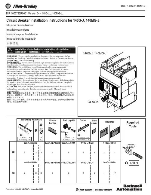
Bul. 140G/140MGInstallation - Installazione - Installation - Installation - Instalación - Instalação - -Circuit Breaker Installation Instructions for 140G-J, 140MG-JIstruzioni di installazione Installationsanleitung Instructions pour l’installation Instrucciones de instalación 安装说明WARNING: To prevent electrical shock, disconnect from power source before installing or servicing. Install in suitable enclosure. Keep free from contaminants.70E requirementsPer prevenire infortuni, togliere tensione prima dell'installazione omanutenzione. Installare in custodia idonea. Tenere lontano da contaminanti. WARNUNG : V or Installations- oder Servicearbeiten Stromversorgung zur Vermeidung von elektrischen Unfällen trennen. Die Geräte müssen in einem passenden Gehäuse eingebaut und gegen Verschmutzung geschützt werden.A VERTISSEMENT: Avant le montage et la mise en service, couper l'alimentation secteur pour éviter toute décharge. Prévoir une mise en coffret ou armoire appropriée. Protéger le produit contre les environnements agressifs.ADVERTENCIA: Desconéctese de la corriente eléctrica, antes de la instalación o del servicio, a fin de impedir sacudidas eléctricas. Instálelo en una caja apropiada. Manténgalo libre de contaminantes.ATENÇÃO: Para evitar choques, desconectar da corrente elétrica antes de fazer a instalação ou a manutenção. Instalar em caixa apropriada. Manter livre de :感電事故防止のため、取付けまたは修理の際は電源から取り外してく確認してください。
第一章 PA150+系列概述1.适用范围PA150+系列微机综合保护测控装置是针对企业电力系统的老款PA150升级而来的新型“四合一”综合保护测控装置,它适用于石化、钢铁、冶金等行业,也适用于电力行业中对保护功能要求比较灵活的场合。
PA150+系列保护测控装置采用先进的技术,精心的设计,使保护和测控既相对独立又相互融合,保护装置工作不受测控和外部通信的影响,确保保护的安全性和可靠性。
PA150 系列保护测控装置不仅支持现场所需的保护、监视、控制功能,还支持综合自动化所需的各种高级应用功能,如故障信息、电量变送功能等,为企业电力系统的安全、稳定、经济运行提供了坚实的基础。
2.主要特点●装置采用全封闭机箱,强弱电严格分开,取消传统背板配线方式,同时在软件设计上也采取相应的抗干扰措施,装置的抗干扰能力大大提高,对外的电磁辐射也满足相关标准。
●硬件资源丰富,开入量可达12 路,提供丰富的信号和出口接点。
●操作回路交、直流配置灵活,可以适应各种操作机构。
●保护功能配置齐全、动作快速、性能可靠。
●具备完善的装置测试功能,方便了现场的调试和检测。
●装置具备软件对时和硬件对时功能。
硬件对时支持GPS 差分秒脉冲对时或者IRIG-B 码对时,装置可自动识别对时方式。
●完善的事件报告处理功能,可保存最新32次动作报告,最新32次S0E变位记录报告,最新32次用户操作记录报告。
●保护功能和通信功能分别由独立的CPU 来实现,网络的状况不影响保护的正常运行。
良好的人机界面、汉字显示、中文报告显示。
●支持一路独立的485 口通信,MODBUS-RTU协议。
●符合《DL/T 478 一2001 静态继电保护及安全自动装置通用技术条件》 规程要求。
●符合《B14285-93 继电保护和安全自动装置技术规程》规程要求。
3.PA150+系列装置液晶显示说明3.1主画面液晶显示说明装置上电后,正常运行时液晶屏幕将循环显示主画面,基本格式如下(以PA150+F1 为例):3.2 保护动作时液晶显示说明本装置能存储32次动作报告,当保护动作时,液晶屏幕自动显示最新一次保护动作报告,当一次动作报告中有多个动作元件时,所有动作元件将循环显示,格式如下:3.3 自检出错时液晶显示说明本装置能存储32 次装置自检报告,保护装置运行中,硬件自检出错将立即显示自检报告,当一次自检报告中有多个出错信息时,所有自检信息将滚屏显示,格式如下:4.PA150+系列装置菜单功能说明在主画面状态下,按‘确认’键可进入主菜单,通过‘↑’、‘↓’、‘确认’和‘取消’键选择子菜单。
HYP1410微机电动机综合保护监控装置使用说明书USER GUIDE®ZHEJIANG HUAYI ELECTRIC POWER AUTOMATION CO.,LTD目录1.适用范围 (4)2.装置功能及保护原理简述 (4)2.1 电气参数测量 (4)2.2速断保护 (4)2.3过热(过负荷)保护 (4)2.4 零序过流(接地)保护 (5)2.5负序过流(不平衡、断相或反相)保护 (5)2.6 低电压保护 (5)2.7自启动控制 (5)2.8启动时间过长保护 (5)2.9堵转保护 (5)2.10 实际启动电流及启动时间显示 (5)2.11过热跳闸记忆及强制复归 (5)2.12过热报警 (6)2.13熔断器熔断报警 (6)2.14 PT断线报警 (6)3.技术参数 (6)4.按键功能及操作方法 (7)4.1按键功能 (7)4.1.1“▼” 搜索键与功能键 (7)4.1.2“◄►” 进入修改状态及移动小数点键 (7)4.1.3“▲” 修改、操作键 (7)4.1.4“■信号复归”键 (7)4.2输入密码的方法: (7)4.3搜索方法(适用于定点显示和定值区的显示): (7)4.4密码种类 (7)5. 数码管的显示种类 (7)5.1 数码管显示说明 (7)5.2几种显示列表 (7)5.2.1循环显示(供运行人员使用) (8)5.2.2定点显示(供运行人员或调试人员用) (8)5.2.3进入定值区的显示(输入密码1111) (8)5.2.4有报警或预告时的显示: (9)6.调试方法(适用于调试人员及维护人员) (9)6.1查看、输入或修改保护定值: (10)6.2开关量的检查 (10)6.3保护继电器的出口检查 (10)®ZHEJIANG HUAYI ELECTRIC POWER AUTOMA TION CO.,LTD36.4模拟量输入检查及精度检查 ......................................................................................................... 10 6.4.1电流校准 .................................................................................................................................... 10 6.4.2电压校准 .................................................................................................................................... 10 6.4.3零序电流校准 ........................................................................................................................... 10 6.5保护定值的整定方法与实例(可供定值计算人员和调试人员参考) ........................................ 11 6.5.1二次侧额定电流整定 ........................................................................................................ 11 6.5.2启动时间整定 ........................................................................................................................... 11 6.5.3速断保护整定 ........................................................................................................................... 11 6.5.4过热保护整定 ........................................................................................................................... 11 6.5.5零序过流(接地)保护整定 .................................................................................................. 11 6.5.6负序过流(不平衡、断相或反相)保护整定 ..................................................................... 11 6.5.7低压保护整定 ........................................................................................................................... 11 6.5.8自启动时间整定 ....................................................................................................................... 11 6.6保护试验 .......................................................................................................................................... 11 6.6.1速断试验 .................................................................................................................................... 12 6.6.2过热特性测试 ........................................................................................................................... 12 6.6.3堵转试验 .................................................................................................................................... 13 6.6.4启动时间过长试验 ................................................................................................................... 13 6.6.5零序过流试验 ........................................................................................................................... 13 6.6.6负序过流试验 ........................................................................................................................... 14 6.6.7低电压试验 ............................................................................................................................... 14 6.6.8自启动试验 ............................................................................................................................... 15 6.6.9动作时间试验 ........................................................................................................................... 15 6.6.10 FC 回路熔断器熔断报警 ...................................................................................................... 15 6.6.11 PT 回路断线报警 ................................................................................................................... 15 6.6.12定值错误报警试验 ................................................................................................................. 15 7、机箱结构及接线图 ............................................................................................................................. 16 7.1机箱结构图与说明 .......................................................................................................................... 16 7.3保护装置的端子图及端子接线说明 ............................................................................................ 17 8.运行人员注意事项及要求 .................................................................................................................... 18 9.检修及维护 ............................................................................................................................................. 18 附录1:HYP1410微机电动机保护装置原理图 ................................................................................. 19 附录2:HYP1410微机电动机保护装置原理接线图 . (20)®ZHEJIANG HUAYI ELECTRIC POWER AUTOMA TION CO.,LTD41.适用范围HYP1410微机电动机保护装置适用于工作电压为 0.4-10KV 的电动机,作为电动机的成套保护和监视报警装置。
Technical DataMotor Protection Circuit Breaker SpecificationsBulletin Number 140-CMNTopic PageProduct Line Overview3Specifications5Approximate Dimensions9Additional ResourcesThese documents contain additional information concerning related products from Rockwell Automation.Resource DescriptionIndustrial Automation Wiring and Grounding Guidelines, publication 1770-4.1Provides general guidelines for installing a Rockwell Automation industrial system. Product Certifications website, Provides declarations of conformity, certificates, and other certification details.Y ou can view or download publications at /literature/. T o order paper copies of technical documentation, contact your local Allen-Bradley distributor or Rockwell Automation sales representative.Motor Protection Circuit Breaker Specifications2Rockwell Automation Publication 140M-TD003A-EN-P - April 2016Product Line OverviewOverviewMotor Protection Circuit Breakers may provide the following protective and control functions.•Disconnect for Motor Branch Circuit•Branch-Circuit, Short-Circuit Protection (Magnetic Protection)•Overload Protection (Thermal Protection)•Switching (Manual)In North America, electrical codes require that an individual Motor Branch Circuit be protected by a UL/CSA Listed Fuse, Circuit Breaker or Self-Protected Combination Motor Controller.The 140-CMN frame Motor Protection Circuit Breakers are UL Listed/CSA Certified as Manual Motor Controllers (with optional approvals for Motor Disconnect and Group Installation). In NEC/CEC Group Installations, these devices must be applied per the appropriate rules which require the use of an upstream Branch-Circuit, Short-Circuit Protective Device (BCPD). See the table on UL/CSA Listed Application Ratings - Motor Protection Circuit Breaker (MPCB) Only for the specific ratings of each Motor Protection Circuit Breaker.Standards Compliance and CertificationsStandards Compliance CertificationsIEC/EN60947-1,-2CE MarkedCSA,C22.2 No.14CSA CertifiedUL508cULus Listed (File No. E54612, NLRV(7); E205542, NKJH(7); E197878, DIVQ(7);)Rockwell Automation Publication 140M-TD003A-EN-P - March 20163Product Line OverviewAttribute140-CMNMax. Current I e90 A Current Rating16…90 A Short Circuit Protection✓Standard Magnetic T rip✓High Magnetic Trip✓Overload Protection✓Trip Class10 Application at output of VFD (multi-motor)Standards Compliance:CSA22.2, No.14✓UL508 (Group Installation)✓ (see ratings) UL508 (Overload Protection)✓IEC60947-1,-2✓CE✓AccessoriesExternal Rotary Operator✓Auxiliary Contacts✓Trip Indication Contacts✓4Rockwell Automation Publication 140M-TD003A-EN-P - March 2016Rockwell Automation Publication 140M-TD003A-EN-P - April 20165SpecificationsIEC Performance DataTable 1 - IEC Performance Data⋆No back-up fuse required.‡ Power ratings: Preferred values according to IEC 60072-1.General DataTable 2 - General DataCat.No.140-CMN…-2500 -4000-6300-9000Rated Operational Current, I e [A]25406390Magnetic Release Current [A]3505608901260Switching of Standard Three-Phase Motors, AC-3230/240V ‡[kW] 5.5/7.510/1113/2022/25400/415V ‡[kW]7.5/1315/2225/3237/45500V ‡[kW]11/1518.5/2530/4045/55690V ‡[kW]15/2225/3037/5563/75Back-Up Fuses gG, gL, only if I cc ≥ I cu230/240V [A]⋆⋆⋆⋆400/415V [A]160160160160500V [A]160160160160690V [A]160160160160Ultimate Short Circuit Breaking Capacity, I cu230/240V [kA]1001005050400/415V [kA]50302020500V [kA]30201010690V [kA]15844Rated Service Short Circuit Breaking Capacity, I cs230/240V [kA]1001005050400/415V [kA]503088500V [kA]301566690V [kA]15844Attribute140-CMNRated Insulation Voltage U iIEC, SEV, VDE0660[V]690UL, CSA[V]600Rated Impulse Withstand Voltage U impPollution degree3Main circuits U imp /Overvoltage Category 6kV/III Auxiliary circuits U imp /Overvoltage Category 6kV/III Rated Frequency[Hz]40 (60)Utilization CategorySpecificationsIEC60947-2 (Circuit breaker)AIEC60947-4-1 (Motor starter)AC-3 (except 90 A)LifespanMechanical[operations]30000Electrical (I e max.)[operations]5000Switching Frequency[operations/h]max.20Ambient TemperatureStorage[°C]-25…+80Operation[°C]-25…+60Climatic resistanceMoisture change climate (600068-2-30)23°C/83% relative humidity and 40°C/92% relative humidity, 56 cycles Dry heat (60086-2-2)100°C, relative humidity <50%, 7 daysMoisture heat (60068-2-3)40°C, relative humidity 93%, 56 daysProtection Class IP2X from front with terminal wired, (min. wire size 35 mm2 or #4 AWG ) Resistance to Shock, Transport (60068-2-27)30g,11 msRated Thermal Current I thup to 40°C ambient temperature[A]16 (90)up to 60°C ambient temperature[A]16 (90)Rated Supply Current I e[A]16 (90)Dependence on Temperature40°C[A]no reduction50°C[A]no reduction60°C[A]no reduction70°C[A]15% current reduction of the upper rated current I eOverload ProtectionCharacteristics IEC60947 Ambient Temperature Compensation[°C]20…+60Phase-loss Protection Differential releaseTrip class10Magnetic Release Release current(+/-20%)fixed setting14 x I e max. Total Power Loss P vCircuit Breaker at rated load operating temperature[W]33Main Disconnect Switch Application Yes, with accessoriesApplication Conditions For utilization outside North America, assemblies (of products) shall comply to the IEC61439-1 requirements Attribute140-CMN6Rockwell Automation Publication 140M-TD003A-EN-P - April 2016Specifications Table 3 - General Data, ContinuedWeightsDescription Weight [g]Cat.No.Motor Protection Circuit Breakers1845140-CMN-…Auxiliary Contacts31140-CA…Undervoltage Trip94140-CUV…Trip Contact Blocks31140-CT…Shunt Trip94140-CRT…Accessories for Bulletin140-CMN Circuit BreakersTable 4 - Accessory SpecificationsRockwell Automation Publication 140M-TD003A-EN-P - April 20167SpecificationsTable 5 - Trip Unit SpecificationsTime-Current CharacteristicFigure 1 - 140-CMN Motor Protection Circuit Breaker Time-Current CharacteristicThermal Release Trip CurrentThe adjustable current-dependent delayed bimetal release protects motorsagainst overload. The curve shows the mean operating current at an ambienttemperature of 20 °C starting from the cold state. Careful testing and settingensures effective motor protection even in the case of single phasing. Theoverload characteristic is also valid for transformer protection.Magnetic Release Trip CurrentThe instantaneous magnetic trip has a fixed operating current setting. Thiscorresponds to 13…14 times the maximum value of setting range. (Transformerprotection up to 20 x I e max.) At a lower setting it is correspondingly higher.Current Setting I e FThe overload trip corresponds to a thermal overload relay in a motor starterconforming to IEC947-4-1. If a different value is prescribed (e.g., reduced I e forcooling medium having a temperature higher than 40 °C or a place of installationhigher than 2000 m above sea level), the setting current is equal to the reducedrated current I e of the motor.8Rockwell Automation Publication 140M-TD003A-EN-P - April 2016Approximate DimensionsDimensions are shown in millimeters (inches). Dimensions are not intended to be used for manufacturing purposes.Figure 2 - 140-CMNRockwell Automation Publication 140M-TD003A-EN-P - April 20169Approximate DimensionsFigure 3 - 140-CD…Figure 4 - Mounting position/safety clearance of Cat. No. 140-CMN10Rockwell Automation Publication 140M-TD003A-EN-P - April 2016Motor Protection Circuit Breaker Specifications Notes:Rockwell Automation Publication 140M-TD003A-EN-P - April 201611Allen-Bradley, Rockwell Software, Rockwell Automation, and LISTEN. THINK. SOLVE are trademarks of Rockwell Automation, Inc.Trademarks not belonging to Rockwell Automation are property of their respective companies.Publication 140M-TD003A-EN-P - April 2016Copyright © 2016 Rockwell Automation, Inc. All rights reserved. Printed in the U.S.A.Rockwell Automation SupportUse the following resources to access support information.Documentation FeedbackY our comments will help us serve your documentation needs better. If you have any suggestions on how to improve this document, complete the How Are W e Doing? form at /idc/groups/literature/documents/du/ra-du002_-en-e.pdf .Technical Support CenterKnowledgebase Articles, How-to Videos, FAQs, Chat, User Forums, and Product Notification /knowledgebase Local Technical Support Phone NumbersLocate the phone number for your /global/support/get-support-now.page Direct Dial CodesFind the Direct Dial Code for your product. Use the code to route your call directly to a technical support /global/support/direct-dial.page Literature LibraryInstallation Instructions, Manuals, Brochures, and Technical /literature Product Compatibility and Download Center(PCDC)Get help determining how products interact, check features and capabilities, and find associated /global/support/pcdc.pageRoc kw ell Otomasyon Ticaret A .Ş., K ar Plaza İş Mer k ezi E B lo k K at:6 34752 İçeren köy, İstanbul, T el: +90 (216) 5698400Rockwell Automation maintains current product environmental information on its website at /rockwellautomation/about-us/sustainability-ethics/product-environmental-compliance.page .。
微机综合保护管理装置使用说明V1.01目录一、系统 (1)1.1 概述 (1)1.2 主要特点 (1)二、技术参数 (1)2.1 辅助电源 (2)2.2 输入信号 (3)三、产品说明 (3)3.1按键定义 (3)3.2信号灯说明 (3)3.3 开孔尺寸 (4)四、监控功能 (4)4.1 电气量测量功能 (4)4.2 开关量输入及输出 (5)4.3 辅助模拟量输出功能(4-20mA标准) (5)4.4通信功能 (5)4.5事件记录功能 (5)4.6 PT、CT变比设置 (5)五、线路综合保护装置 (6)5.1 装置功能 (6)5.2线路综合保护装置人机操作说明 (12)5.3线路综合保护装置接线图 (16)六、变压器保护装置 (16)6.1装置功能 (16)6.2 变压器保护人机操作说明 (21)6.3变压器保护接线原理图 (25)七、电动机保护装置 (26)7.1 装置功能 (26)7.2 电动机保护人机操作说明 (32)7.3电动机保护器接线原理图 (36)八、电容器保护装置 (36)8.1 装置功能 (36)8.2 电容器保护人机操作说明 (42)8.3电容器保护器接线原理图 (46)九、电流保护装置 (46)9.1装置功能 (46)9.2 电流保护人机操作说明 (49)9.3电流保护器接线原理图 (53)十、电压保护装置 (53)10.1 装置功能 (53)10.2 电压保护人机操作说明 (55)10.3电压保护接线原理图 (59)附表一、测量数据区数据点表 (60)附表二、数据控制区数据点表 (60)附表三、保护数据区数据点表 (61)附表四、系统数据区数据点表 (62)附表五、厂家数据区数据点表 (62)附表六、厂家数据区数据点表 (63)微机综合保护装置一、系统1.1 概述微机综合保护装置系列数字式智能保护测控管理装置采用高性能DSP数字处理器,研制成的新一代智能保护测控管理装置。
装置适应于110KV以下电压等级的线路、变压器、电动机、电容器等各种电力装备的保护。
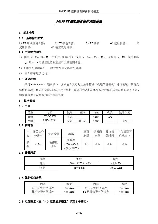
PA150-PT微机综合保护测控装置1 基本功能1.1 基本保护配置1)PT断线检测告警;2)PT接地告警;3)PT切换;4)过压告警;5)欠压告警;6)装置故障告警。
1.2 主要测控功能1)相电压:Ua、Ub、Uc(三相三线时没有);线电压:Uab、Ubc、Uca;负序电压:U2;零序电压U0;频率:f等模拟量的测量显示以及遥测功能;2)4路信号量的输出、1路装置失电故障信号输出。
3) 事件顺序记录功能。
1.4 通讯功能采用RS485/RS422通讯接口,各功能单元可与主控计算机(或通信管理机)进行通讯,从而实现信息的远方传送和交换。
通过主控计算机(或通信管理机)还可实现对保护装置定值的远方查询、整定功能以及对装置的远方控制功能。
2技术数据2.1 电源类型 电压 波形 频率 功耗 纹波 波形失真直流 100V~250V 直流 ——— <20W <5% ———交流 85V~265V 交流 50±5Hz<20W ——— <5%2.2 实时性内容 开关动作分辨率数据采集 通讯画面刷新调画面时间接口报警时间上位机到下位机命令参数 <2ms模拟量≤1s波特率1200~9000(默认4800)≤1s ≤1s ≤1s ≤1s2.3 计量精度内容 条件 精度电压 (20%~120%)×Un <±0.2%频率 45~55Hz <±0.02Hz2.4 保护性能参数内容 参数 内容 参数 过压告警时间误差<±15ms 欠压告警时间误差<±15ms接地告警时间误差<±15ms PT断线告警时间误差<±15ms 2.5 定值整定(在“3.3 定值显示整定”子菜单中整定)序号 名称 单位 符号 整定值范围 分辨率 000 PT 断线时间 s Tdx 0.1~500s 0.01s 001 PT 接地时间 s Tjd 0.1~500s 0.01s 002 零序告警电压值 V U 0zd 0.1~1.2×U 0.01V 003 过压告警电压值 V Uhzd 0.5~1.2×U 0.01V 004 过压告警时间值 s Th 0.1~500s 0.01s 005 欠压告警电压值 V ULzd 0.1~1.0×U0.01V 006 欠压告警时间值sTL0.1~500s0.01s注1 U 为线电压额定值,默认为100V。
PA100+系列微机综合保护测控装置一、前面板布置及操作装置面板布置前面板有以下六部分组成1、320x240大屏幕图形液晶显示器LCD,用于显示操作菜单、各种运行数据、参数、波形及状态。
2、七个LED工作状态指示灯,分别为:分闸、合闸、通讯、故障、告警、运行及遥控。
3、编程窗口。
4、LCD液晶背光电源亮度调节孔。
5、八个操作按钮,分别为:分闸、合闸、方向键(向左、向右、向上、向下)、确认、取消。
6、一个三位锁,用于设置本装置以下三种工作模式:遥控、本地和设置。
操作按键分合操作按键分合操作按键用于本地控制可操作的电力设备,如断路器的分合控制。
在操作时面板上锁必须在本地控制。
操作过程分为操作预令和操作动令两个步骤,按键按第一下时启动操作预令,相应的分合闸指示灯闪烁,单元处于“操作预令”状态。
此间,第二次按动同一操作按键(动令确认),单元方可执行相应操作。
预令与动令操作时间必须在0.5---5秒内,当时间少于0.5秒时动令不被确认,当时间超过5秒,预令过程将自动结束,动令确认不被认可,操作过程必须重新开始。
三位锁开关三位锁开关指向“遥控”位置时,为允许遥控状态,断路器的分合操作由远方遥控实施,前面板的分合按键将不起作用。
并可实现远方保护投退、遥控开关、复归故障指示等下行操作。
三位锁开关指向“本地“位置时,为本地操作状态,此时断路器的分合操作由操作人员在本地通过前面板分合按键操作。
三位锁指向“设置“位置时,为允许设置状态,此时单元将进入设置工作状态。
LCD 显示设定选择菜单,可在本地通过方向键、”确认“、”取消“或在远方进行保护定值设置、修订等操作,并可将整定后的数据存入EEPROM 中永久保存。
二、 主菜单主菜单显示如下图:01、一次系统图02、事件记录03、测量数据04、开入开出显示05、保护定制显示06、系统状态07、图形数据08、单元型号09、设备参数10、出厂设置21.通用事件记录22.保护事件记录23.事件记录管理31.基本数据32.对称数据33.谐波数据34.功率数据35.电量数据36.差动数据41.开入开出状态42.开入状态数据71.定时波形图72.向量图73.故障录波图74.启动波形图91.时间设置92.串行通讯监测93.串行通讯设置94.以太网监测95.以太网设置96.线路参数设置97.语言设置98.口令设置99.仿真运动数据9A.电度设置101.通道系统整定102.开入量参数103.开出量参数104.恢复出厂设置105.通道零点106.开出测试107.测量量程设置108.DATAFLASH 109.DA 系统整定主菜单界面下,被选择的子菜单呈反显状态,按方向键选择子菜单,再按“确认“键,即可进入相应的子菜单,屏幕显示相应的子菜单内容。
第一章 PA150+系列概述1.适用范围PA150+系列微机综合保护测控装置是针对企业电力系统的老款PA150升级而来的新型“四合一”综合保护测控装置,它适用于石化、钢铁、冶金等行业,也适用于电力行业中对保护功能要求比较灵活的场合。
PA150+系列保护测控装置采用先进的技术,精心的设计,使保护和测控既相对独立又相互融合,保护装置工作不受测控和外部通信的影响,确保保护的安全性和可靠性。
PA150 系列保护测控装置不仅支持现场所需的保护、监视、控制功能,还支持综合自动化所需的各种高级应用功能,如故障信息、电量变送功能等,为企业电力系统的安全、稳定、经济运行提供了坚实的基础。
2.主要特点●装置采用全封闭机箱,强弱电严格分开,取消传统背板配线方式,同时在软件设计上也采取相应的抗干扰措施,装置的抗干扰能力大大提高,对外的电磁辐射也满足相关标准。
●硬件资源丰富,开入量可达12 路,提供丰富的信号和出口接点。
●操作回路交、直流配置灵活,可以适应各种操作机构。
●保护功能配置齐全、动作快速、性能可靠。
●具备完善的装置测试功能,方便了现场的调试和检测。
●装置具备软件对时和硬件对时功能。
硬件对时支持GPS 差分秒脉冲对时或者IRIG-B 码对时,装置可自动识别对时方式。
●完善的事件报告处理功能,可保存最新32次动作报告,最新32次S0E变位记录报告,最新32次用户操作记录报告。
●保护功能和通信功能分别由独立的CPU 来实现,网络的状况不影响保护的正常运行。
良好的人机界面、汉字显示、中文报告显示。
●支持一路独立的485 口通信,MODBUS-RTU协议。
●符合《DL/T 478 一2001 静态继电保护及安全自动装置通用技术条件》 规程要求。
●符合《B14285-93 继电保护和安全自动装置技术规程》规程要求。
3.PA150+系列装置液晶显示说明3.1主画面液晶显示说明装置上电后,正常运行时液晶屏幕将循环显示主画面,基本格式如下(以PA150+F1 为例):3.2 保护动作时液晶显示说明本装置能存储32次动作报告,当保护动作时,液晶屏幕自动显示最新一次保护动作报告,当一次动作报告中有多个动作元件时,所有动作元件将循环显示,格式如下:3.3 自检出错时液晶显示说明本装置能存储32 次装置自检报告,保护装置运行中,硬件自检出错将立即显示自检报告,当一次自检报告中有多个出错信息时,所有自检信息将滚屏显示,格式如下:4.PA150+系列装置菜单功能说明在主画面状态下,按‘确认’键可进入主菜单,通过‘↑’、‘↓’、‘确认’和‘取消’键选择子菜单。
P40M系列电动机保护装置使用说明书(V1.5)河南森尼瑞电气有限公司目录1装置简介 (1)2技术指标 (3)3保护功能及原理 (5)4保护信息说明 (14)5测控功能 (18)6人机接口说明 (19)7背板端子和接线原理图 (22)8机箱结构 (27)9装置选型 (28)10投运说明及注意事项 (28)11贮存及保修 (29)注:本资料版权为河南森尼瑞电气有限公司所有,受版权法的保护,使用仅限于森尼瑞电气的用户,未经本公司书面许可,不得以任何形式和方式提供给第三者,同时本公司保留对资料的修改和解释权。
1装置简介P40M系列微机电动机保护装置适用于3kV~10kV电压等级的中高压异步电动机的保护及测控,既可以直接安装在开关柜上,也可组屏安装。
其中P41M微机电动机保护用于2000kW 以下中小型异步电动机的保护;P42M微机电动机保护用于2000kW及以上大型异步电动机的保护。
1.1功能配置1.2装置主要特点●加强型单元机箱按抗强振动、强干扰设计,特别适应于恶劣环境,可分散安装于开关柜上运行。
集成电路全部采用工业品或军品,使得装置有很高的稳定性和可靠性。
●采用32位ARM作为CPU,采用实时多任务嵌入式操作系统。
保护功能不依赖通讯网,网络瘫痪与否不影响保护的正常运行。
●采用大屏幕汉字液晶显示,能显示多种测量参数,能查看运行状态,能显示或修改保护定值。
人机界面友好,信息详细直观,操作、调试方便。
●大容量的信息记录。
可保存不小于1000个最近发生的动作报告、事件记录、复位报告、开机时间、关机时间、掉电时间等,便于事故分析。
●具备录波功能。
装置记录保护动作前后25个周波(每周波64点)的采样数据,能就地液晶界面显示,保护跳闸后上送配电自动化系统主站,也可以通过故障分析软件进行故障分析。
●有独立测量CT,具有“综合保护”和“测量仪表”功能,带31次谐波测量,一个装置具有两种功能,为用户节省成本。
●完善的软硬件自检功能。
(127 146)PA100+ M技术说明书V05.40(127-146)pa100+-m技术说明书v05.40intpa100+-m微机综合保护测控装置pa100+-m保护装置此装置适用于3~10kv电压等级的电动机保护。
1基本保护配置1)启动维护(启动过长维护)2)三段电流保护(三段保护均可以选择4种反时限和定时限)3)过负荷保护4)堵转保护5)负序维护(负序ⅰ段、负序ⅱ段)6)中剧维护(ⅰ段i0、ⅱ段i0)7)零序过载维护8)过电压、低电压9)低频减载(可设低压、滑差闭锁)10)过热保护(过热告警和过热跳闸)11)温度保护(温度告警和温度跳闸)12)大电流闭锁13)非电量保护14)tv监测(tv断线和tv相序推论)15)ta监测(保护ta断线和相序判断、测量ta断线和相序判断)16)控制回路断线监测-127-intpa100+-m微机综合保护测控装置17)装置故障监视系统2主要测控功能1)本地或遥控断路器分合闸。
2)16路开进信号量的收集,除部分存有特定定义外,其余开进量可以由用户定义。
本单元上开进信号存有两种互连方式可以供选择:一种有源接点,外接电源;另一种就是无源接点,本装置提供更多电源。
具体内容起身见到附图5。
用户在订货时需表明。
3)测量数据基本数据――线电压:uab、ubc、uca;相电压:ua、ub、uc(三相三线时没有);保护电流:ia、ib、ic;测量电流:ia、ib、ic;零序电流i0;零序电压:u0;a相电压频率:f(ua);零序电压频率:f(u0);滑差:df/dt;热量:qn。
等距分量――电压等距分量:u1、u2、3u0;测量电流等距分量:i1、i2、3i0;维护电流等距分量:pi1、pi2、3pi0。
谐波数据――测量电流(ia、ib、ic)、测量电压(ua、ub、uc)、保护电流(ia、ib、ic)的有效值、基波、二次、三次、五次谐波。
功率数据――二次值表明的存有:军功功率p、无功功率q、功率因数cos、单相军功功率(pa、pb、pc)、-128-intpa100+-m微机综合维护测控装置单相无功功率(qa、qb、qc);一次值显示的有:有功功率p、无功功率q。
PA140微机综合保护概论PA140系列综合微机保护测控装置(以下简称装置是南京因泰莱电器股份有限公司(INT针对对中国10KV以下电力系统进行广泛的调研,在总结具有丰富运行经验的PA100、PA100+、PA200系列产品基础上,采用国内外先进技术,独立研发的又一代全新产品,它是多方面技术的完美结合。
本系列装置采用计算机技术、电力自动化技术、通讯技术等多种高新技术,集保护、测量、控制、监测、通讯、事件记录、故障录波上传等多种功能于一体。
可就地安装在开关柜上或集中组屏,是构成变电站、发电厂厂用电综合自动化系统的理想智能终端装置。
PA140系列保护装置型号和主要应用范围如下:¾PA140-F1:10KV以下各种接地方式的馈线保护,可以根据要求采用单相、两相或三相过流保护和接地故障保护。
¾PA140-F2:10KV以下进线、馈出线分支的短路、接地、低电压及非电量保护等,同时也适用于厂用电等设备的保护。
¾PA140-C:10KV以下各种运行方式的电力电容器保护。
¾PA140-M:10KV以下各种运行方式的电动机保护。
¾PA140-V:10KV以下PT运行状况的监控。
一、PA140系列综合数字继电器的特点1.1、PA140系列综合数字继电器不仅拥有继电保护完整的保护功能,而且对所有测量量进行数字化的处理和计算,保证了继电保护的可靠性和安全性。
它彻底抛弃了旧式继电保护装置的体积大、二次接线繁琐的缺点,同时它还具有测量、电力系统自动化远方终端的功能。
1.2、友好的人机界面,大屏幕图形LCD显示器,全中文显示,信息量大,各种数据、参数、波形一览无遗。
1.3、具有高可靠性。
所有元件采用工业级CMOS芯片,在机箱设计、电源设计、电路设计上总体考虑了电磁兼容性,具有极强的抗干扰能力。
1.4、事件顺序记录,直接使用汉字显示事件及保护动作信息,且掉电不丢失,累加记录。
1.5、故障录波上传功能,提供了分析事故的第一手资料。
微机线路及逆功率综合保护测控装置技术说明书西安西电自动化控制系统有限公司1目录1.概述 (3)2.主要特点及功能 (3)3.技术参数 (4)3.1机械及环境参数 (4)3.2额定电气参数 (4)3.3主要技术指标 (4)4装置硬件说明 (5)5软件说明 (6)6基本保护配置 (10)7主要测控功能 (11)8装置整定内容 (12)8.1定值整定清单 (12)8.2开入量参数整定 (13)8.3开出量参数整定 (14)9主要保护功能原理 (15)9.1低压方向闭锁三段式电流保护 (15)9.2过负荷保护 (18)9.3三相一次重合闸、后加速 (18)9.4低频减载 (19)9.5 低电压 (19)9.6两段零序过流保护(Ⅰ段I0、Ⅱ段I0) (20)9.7零序过压保护 (20)9.8逆功率保护 (21)9.9非电量保护 (21)9.10 TV监测 (21)9.11 TA监测 (22)9.12控制回路断线告警 (23)9.13装置故障告警 (24)10装置背板端子定义及接线示意 (24)1概述IHD6201、IHD6224微机综合保护测控装置是西安西电自动化控制系统有限责任公司在总结了现有系列产品运行经验的基础上,融合了国内外先进技术,采用了基于ARM9内核32位的闪存微控制器,根据中国电力系统的需求自主研制和生产的产品。
本系列装置采用了计算机技术、电力自动化技术、通讯技术等多种高新技术,集保护、测量、控制、监测、通讯、事件记录、故障录波、远程I/O等多种功能于一体。
可就地安装在开关柜上或集中组屏,是构成变配电所和发电厂厂用电综合自动化系统的理想智能终端装置。
2主要特点及功能2.1保护功能齐备:各型号保护功能齐备,并可按照用户要求进行定制。
2.2逻辑功能:各保护功能和继电器出口具有逻辑组态功能,可按用户要求进行设定,可设保护动作信号量输出功能;开关量可通过设定实现非电量保护功能;开关量可实现闭锁保护功能。