采用多区域邻接配置的OSPF示例-Cisco
- 格式:pdf
- 大小:297.38 KB
- 文档页数:10
实验1 配置OSPF末节区域一、实验目的通过本节实验了解OSPF末节区域。
二、实验需要的知识点如图在区域1里面没有始发类型5的LSA,因为它可以配置成一个末梢区域。
注意,当一个相连的区域被配置成一个末梢区域时,路由器始发的Hello报文进入那个区域后,它的可选字段中的E位将会设置为0。
其他没有同样配置的所有路由器受到这些Hello报文后将会自动丢弃。
并且不能在这些路由器之间建立邻接关系。
三、实际生活中的应用为了减少LSA通告,减轻CPU负担。
在可以的情况下,建议使用末节区域。
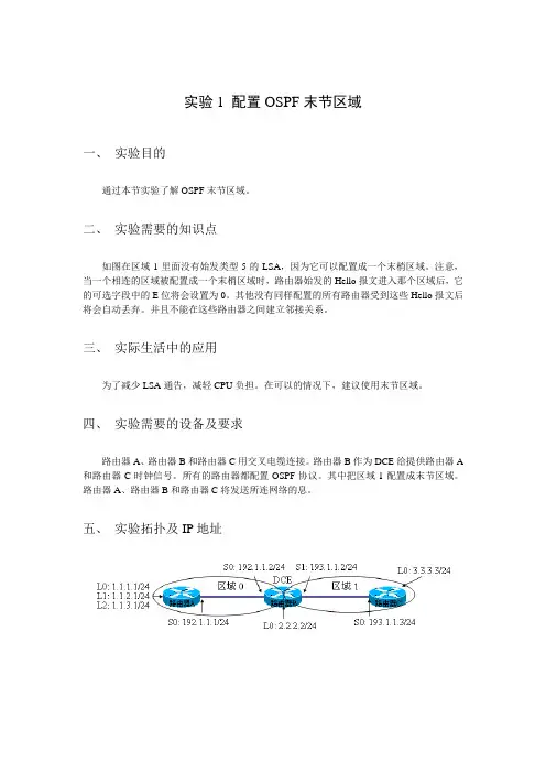
四、实验需要的设备及要求路由器A、路由器B和路由器C用交叉电缆连接。
路由器B作为DCE给提供路由器A 和路由器C时钟信号。
所有的路由器都配置OSPF协议。
其中把区域1配置成末节区域。
路由器A、路由器B和路由器C将发送所连网络的息。
五、实验拓扑及IP地址六、实验步骤1、给路由器分别命名主机名。
例如:路由器A:RouterA。
定义进入特权模式的密码为:cisco。
在全局模式下使用指令的关键字:hostname nameenable password2、根据拓扑图配置接口IP地址。
在全局模式下使用指令的关键字:interface interface在接口模式下使用指令的关键字:ip address ip-address mask3、在DCE端配置时钟。
在接口模式下使用指令的关键字:clock rate clock。
4、分别在3台路由器上运行ospf,并做通告。
在全局模式下使用指令的关键字:router ospf process-id在协议模式下使用指令的关键字:network address wildcard-mask area area-id5、分别在路由器B和路由器C配置ospf stub 区域在协议模式下使用指令的关键字:area area-id stub6、在路由器A上把环回口重分布到ospf中在协议模式下使用指令的关键字:redistribute connect subnets修改路由器B和C的环回口ospf的类型。
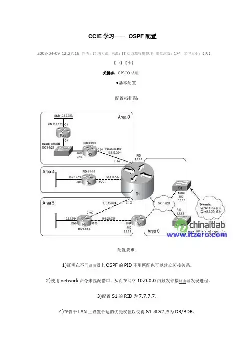
CCIE 学习—— OSPF 配置2008-04-09 12:27:16 作者:IT 动力源 来源:IT 动力源收集整理 浏览次数:174 文字大小:【大】【中】【小】关键字:CISCO 认证●基本配置 配置拓扑图:配置要求:1)证明在不同路由器上OSPF 的PID 不用匹配也可以建立邻接关系。
2)使用network 命令来匹配借口,从而在网络10.0.0.0内触发邻接路由器发现进程。
3)配置S1的RID 为7.7.7.7。
4)在骨干LAN 上设置合适的优先权值以使得S1和S2成为DR/BDR 。
5)在骨干LAN上配置dead间隔为最小(1秒),它是hello间隔的4倍,所以hello间隔为250毫秒。
6)配置区域3为完全NSSA区域,区域4为完全桩区域,区域5为桩区域。
具体配置:1)R1的配置:interface FastEthernet0/0ip address 10.1.1.1 255.255.255.0ip ospf dead-interval minimal hello-multiplier 4!router ospf 1area 3 nssa no-summaryarea 4 stub no-summaryarea 5 stubnetwork 10.1.0.0 0.0.255.255 area 0network 10.3.0.0 0.0.255.255 area 3network 10.4.0.0 0.0.255.255 area 4network 10.5.0.0 0.0.255.255 area 52)R2的配置:interface FastEthernet0/0ip address 10.1.1.2 255.255.255.0ip ospf dead-interval minimal hello-multiplier 4!router ospf 2area 5 stubnetwork 10.1.0.0 0.0.255.255 area 0network 10.5.25.2 0.0.0.0 area 53)R3的配置:router ospf 1area 3 nssa no-summarynetwork 10.0.0.0 0.255.255.255 area 34)R4的配置:router ospf 1area 4 stub no-summarynetwork 10.0.0.0 0.255.255.255 area 45)S1的配置:interface Vlan1ip address 10.1.1.3 255.255.255.0ip ospf dead-interval minimal hello-multiplier 4ip ospf priority 255!router ospf 1router-id 7.7.7.7network 10.1.0.0 0.0.255.255 area 06)S2的配置:interface Vlan1ip address 10.1.1.4 255.255.255.0ip ospf dead-interval minimal hello-multiplier 4ip ospf priority 254!router ospf 1network 10.0.0.0 0.255.255.255 area 0●OSPF的开销以及怎样重启OSPF进程IOS确定OSPF接口开销的方法:1)使用neighbor neighbor cost value命令对每台邻接路由器设置开销(对于允许使用neighbor命令的网络类型)。
实验9-3OSPF多区域配置实验9-3 OSPF多区域配置一、原理概述在OSPF单区域中,每台路由器都需要收集其他所有路由器的链路状态信息,如果网络规模不断扩大,链路状态信息也会随之不断增多,这将使得单台路由器上链路状态数据库非常庞大,导致路由器负担加重,也不便于维护管理。
为了解决上述问题,OSPF协议可以将整个自治系统划分为不同的区域(Area),就像一个国家的国土面积很大时,会把整个国家划分为不同的省份来管理一样。
链路状态信息只在区域内部泛洪,区域之间传递的只是路由条目而非链路状态信息,因此大大减小了路由器的负担。
当一台路由器属于不同区域时称它为区域边界路由器(Area Border Router,ABR),负责传递区域间路由信息。
区域间的路由信息传递类似距离矢量算法,为了防止区域间产生环路,所有非骨干区域之间的路由信息必须经过骨干区域,也就是说非骨干区域必须和骨干区域相连,且非骨干区域之间不能直接进行路由信息交互。
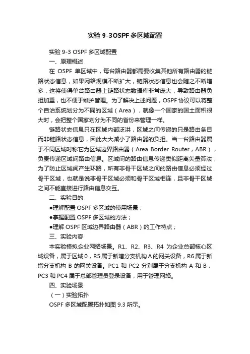
二、实验目的●理解配置OSPF多区域的使用场景;●掌握配置OSPF多区域的方法;●理解OSPF区域边界路由器(ABR)的工作特点;三、实验内容本实验模拟企业网络场景。
R1、R2、R3、R4为企业总部核心区域设备,属于区域0,R5属于新增分支机构A的网关设备,R6属于新增分支机构B的网关设备。
PC1和PC2分别属于分支机构A和B,PC3和PC4属于总部管理员登录设备,用于管理网络。
四、实验场景(一)实验拓扑OSPF多区域配置拓扑如图9.3所示。
图9.3 OSPF多区域配置拓扑(二)实验编址实验编址见表9-3表9-3 实验编址五、实验过程任务一基本自己置根据实验编址表进行相应的基本配置,并使用ping命令检测各直连链路的连通性。
ping 10.0.15.5(详细记录操操作过程及回显结果)测试通过,其余直连网段的连通性测试省略。
任务二配置骨干区域路由器在公司总部路由器R1、R2、R3、R4上创建OSPF进程,并在骨干区域0视图下通告总部各网段。
![思科路由协议配置OSPF多区域[整理]](https://uimg.taocdn.com/36b3706503768e9951e79b89680203d8ce2f6a85.webp)
思科路由协议配置OSPF多区域多区域的OSPFOSPF的区域类型:骨干区域:是OSPF网络的核心,负责连接所有的非骨干区域,区域之间的通讯必须通过骨干区域才能完成,也就是说在OSPF的多区域网络中必须存在骨干区域。
骨干区域的编号为0,area 0 就是骨干区域。
非骨干区域:区域编号为非0数值的OSPF区域。
OSPF的通讯类型:域内通讯量:区域内部网络之间的互相通讯。
域间通讯量:区域之间网络之间的互相通讯。
外部通讯量:OSPF网络与非OSPF网络之间的通讯。
OSPF路由器的类型:IR 域内路由器ABR 区域边界路由器BR 骨干路由器ASBR 自治系统边界路由器OSPF多区域网络中的LSA类型:LSA1:是由每台OSPF路由器产生,始发本机接口所连接链路的信息。
LSA1只在区域内部进行泛洪,可以实现域内的路由通讯。
LSA2:在多路访问型的网络中出现,由DR产生,发送给DRother的汇总后的LSA更新。
地址使用224.0.0.6,只在区域内部泛洪,实现的也是域内通讯。
LSA3:是由ABR域间路由器始发,泛洪到一个区域其所能到达的其他区域的路由信息。
实现域间路由信息的传递,ABR要宣告给它所连接的所有区域,最终实现域间的通讯。
LSA4:是由ABR始发,宣告到一个区域,宣告ASBR的位置信息。
告诉内部去往OSPF外部出口的路由信息。
LSA5:是由ASBR自治系统边界路由器产生,描述其所能到达的OSPF 外部路由信息,该更新将在整个OSPF自治系统中泛洪。
LSA7:NSSA中特有的外部路由更新。
为了实现对NSSA区域的优化,优化掉第4、5种类型的更新,又不会影响到其所连接的外部路由信息,在NSSA区域内部使用LSA7,来通告其所连接的外部路由信息,当LSA7经过ABR区域边界路由器时,会被转化成LSA5,因为对于其他区域来讲,外部路由就是LSA5。
ospf的路由类型:C 直连路由R rip路由D eigrp的内部路由D EX eigrp的外部路由O ospf的域内路由O IA ospf的域间路由O E2 ospf的2类外部路由O E1 ospf的1类外部路由O*IA OSPF的默认路由O N1 OSPF的NSSA区域的1类外部路由O N2 OSPF的NSSA区域的2类外部路由路由重分发,使rip、eigrp和ospf进行路由信息交换rip到ospfr1(config)#router ospf 10r1(config-router)#redistribute rip metric 20 subnetseigrp到ospfr7(config)#router ospf 10r7(config-router)#redistribute eigrp 10 metric-type 1 metric 30 subnetsospf 到 ripr1(config)#router ripr1(config-router)#redistribute ospf 10 metric 2ospf 到 eigrpr7(config)#router eigrp 10r7(config-router)#redistribute ospf 10 metric 1000 100 255 1 1500r4#show ip ospf database //查看ospf的LSDB末梢区域的配置ABRr2(config)#router ospf 10r2(config-router)#area 1 stubIRr4(config)#router ospf 10r4(config-router)#area 1 stubr5(config)#router ospf 10r5(config-router)#area 1 stub在末梢区域的基础上配置完全末梢区域在ABR上配置r2(config)#router ospf 10r2(config-router)#area 1 stub no-summary配置NSSA区域ABRr3(config)#router ospf 10r3(config-router)#area 2 nssar3(config-router)#area 2 nssa default-information-originater3(config-router)#area 2 nssa no-summary //优化掉LSA3IRr6(config)#router ospf 10r6(config-router)#area 2 nssaASBRr7(config)#router ospf 10r7(config-router)#area 2 nssaOSPF的外部路由r1(config-if)#int s0/0r1(config-if)#ip ospf cost 5 //定义OSPF的接口链路度量值r1(config-if)#int s0/1r1(config-if)#ip ospf cost 30r1(config-if)#router ospf 10r1(config-router)#network 0.0.0.0 0.0.0.0 area 0r2(config)#int s0/0r2(config-if)#ip add 192.168.11.2 255.255.255.0r2(config-if)#no shutdownr2(config-if)#ip ospf 10 area 0 //将该接口宣告到ospf 10 的区域0r2(config-if)#ip ospf cost 5将RIP充分发到OSPF,选择1类外部路由r2(config)#router ospf 10r2(config-router)#redistribute rip metric-type 1 metric 20 subnetsr2(config-router)#exitr3(config)#router ospf 10r3(config-router)#redistribute rip metric-type 1 metric 10 subnets选择2类外部路由r2(config)#router ospf 10r2(config-router)#no redistribute rip metric-type 1 metric 20 subnetsr2(config-router)#redistribute rip metric 20 subnetsr3(config)#router ospf 10r3(config-router)#no redistribute rip metric-type 1 metric 10 subnetsr3(config-router)#redistribute rip metric 10 subnetsr1#clear ip ospf process //重启下OSPF进程在OSPF多区域网络中必须存在骨干区域,区域0,因为所有的域间通讯必须要通过骨干区域。
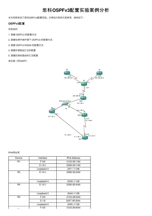
思科OSPFv3配置实验案例分析本⽂实例讲述了思科OSPFv3配置实验。
分享给⼤家供⼤家参考,具体如下:OSPFv3配置实验⽬的1. 掌握 OSPFv3 的配置⽅法2. 掌握在帧中继环境下 OSPFv3 的配置⽅法3. 掌握 OSPFv3 NSSA 的配置⽅法4. 掌握外部路由汇总的配置5. 掌握区域间路由的汇总配置拓扑图(同OSPF)IPv6地址表Device Interface IPv6 AddressR1 F 0/02123::65:1/64S 1/0.12356::65:1/64Loopback 02011::1/128R3S 1/0.12356::65:3/64Loopback 02033::1/128R4S 1/0.12356::65:4/64Loopback 02044::1/128R5 F 0/02123::65:5/64S 1/02027::65:5/64:Loopback 02055::1/128F 0/02123::65:6/64R6R6F 0/02123::65:6/64 Loopback 02066::1/128R7S 1/02027::65:7/64: Loopback 02077::1/128Device Interface IPv6 Address帧中继R2配置与ospfv2相同。
1.完成接⼝ IPv6 地址的配置,注意不要忘记配置 loopback0:R1(config)#ipv6 unicast-routing ―――全局打开 IPv6 路由功能R1config)#interface loopback 0R1(config-if)#ipv6 enableR1(config-if)#ipv6 address 2011::1/128―――配置 loopback0 接⼝地址R1(config-if)#int f 0/0R1(config-if)#ipv6 enableR1(config-if)# ipv6 address 2123::65:1/64R1(config-if)#no shutR1(config-if)#int s 1/0R1(config-if)#ipv6 enableR1(config-if)# encapsulation frame-relayR1(config-if)#no shutR1(config)#interface serial 1/0.1 multipointR1(config-subif)#ipv6 address 2356::65:1/64R1(config-subif)#frame-relay map ipv6 2356::65:3 103 broadcastR1(config-subif)#frame-relay map ipv6 2356::65:4 104 broadcastR1(config-subif)#frame-relay map ipv6 2356::65:1 104 broadcastR1(config-subif)#frame-relay map ipv6 FE80::C804:1CFF:FE48:8 104 broadcastR1(config-subif)#frame-relay map ipv6 FE80::C803:1CFF:FE48:8 103 broadcastR3(config)#ipv6 unicast-routingR3(config)#interface loopback 0R3(config-if)#ipv6 address 2033::1/128R3(config-if)#int s 1/0R3(config-if)#ipv6 enableR3(config-if)# encapsulation frame-relayR3(config-if)#no shutdownR3(config)#interface serial 1/0.1 multipointR3(config-subif)#ipv6 address 2356::65:3/64R3(config-subif)#frame-relay map ipv6 2356::65:1 301 broadcast (R4⽤401)R3(config-subif)#frame-relay map ipv6 2356::65:4 301 broadcast (R4⽤401)R3(config-subif)#frame-relay map ipv6 2356::65:3 301 broadcast (R4⽤401)R3(config-subif)#frame-relay map ipv6 FE80::C804:1CFF:FE48:8 304 broadcast(R4⽤C803,403)R3(config-subif)#frame-relay map ipv6 FE80::C801:1CFF:FE48:8 301 broadcast (R4⽤401)试R1上ping通 R3.R4⽤show frame-relay pvc命令查看,帧中继配置完成2. 按实验拓扑图标识的区域,完成 OSPFv3 的基本配置。
思科路由器设置OSPF推荐文章路由器设置端口映射方法是什么热度:双路由器时设置连接方法和单路由器一样吗热度:路由器UPNP是什么怎么设置热度:Linksys无线路由器怎么样设置热度:怎么设置cisco思科无线ap 热度:OSPF也称为接口状态路由协议,OSPF路由协议是一种典型的链路状态(Link-state)的路由协议,一般用于同一个路由域内有不少用户不知道cisco怎么设置ospf?店铺为大家分享了具体操作方法,供大家参考!思科路由器设置OSPF命令参考以下步骤:router(config)#router ospf 1 启动OSPF路由进程router(config-router)#router-id 1.1.1.1 配置Router IDrouter(config-router)#network 1.0.0.0 0.255.255.255 area 0 指定OSPF协议运行的接口和所在的区域多区域OSPF:router(config)#router ospf 1router(config-router)#router-id 1.1.1.1router(config-router)#network 1.0.0.0 0.255.255.255 area 0 router(config-router)#network 2.0.0.0 0.255.255.255 area 1 末梢区域:router(config)#area1 stub完全末梢区域:router(config)#area1 stub no-summary路由重分发配置:router ripredistribute ospf 10 metric 10router ospf 10redistribute rip metric 10 subnetsNSSA区域配置:router(config)#area1 nssa虚链路配置:router(config)#area 100 virtual-link 1.1.1.1对方RID 店铺分享了cisco设置ospf的解决方法,希望大家喜欢。
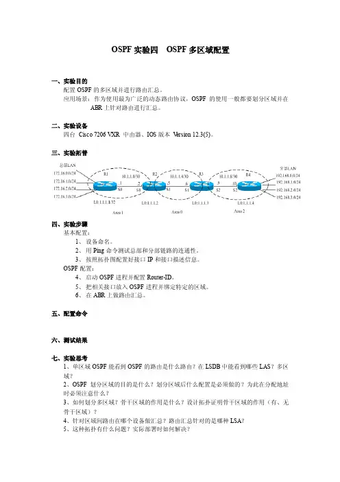
OSPF实验四OSPF多区域配置
一、实验目的
配置OSPF的多区域并进行路由汇总。
应用场景:作为使用最为广泛的动态路由协议,OSPF的使用一般都要划分区域并在ABR上针对路由进行汇总。
二、实验设备
四台Cisco 7206 VXR 中由器、IOS版本V ersion 12.3(5)。
三、实验拓普
四、实验步骤
基本配置:
1、设备命名。
2、用Ping命令测试总部和分部链路的连通性。
3、按照拓扑图配置好接口IP和接口描述信息。
OSPF配置:
4、启动OSPF进程并配置Router-ID。
5、把相关接口放入OSPF进程并绑定特定的区域。
6、在ABR上做路由汇总。
五、配置命令
六、测试结果
七、实验思考
1、单区域OSPF能看到OSPF的路由是什么路由?在LSDB中能看到哪些LAS?多区
域?
2、OSPF划分区域的目的是什么?划分区域后什么配置是必须做的?为此在分配地址
时必须注意什么?
3、如何划分多区域?骨干区域的作用是什么?设计拓扑证明骨干区域的作用(有、无
骨干区域)?
4、针对区域间路由在哪个设备做汇总?路由汇总针对的是哪种LSA?
5、这种拓扑有什么问题?实际部署时如何解决?
6、不希望其他区域看到本区域的设备及链路IP,如何实现?
7、LSA1、LSA2、LSA3分别是哪个设备产生的?作用是什么?各自的关系是什么?查看LSA具体的内容?并尝试读解。

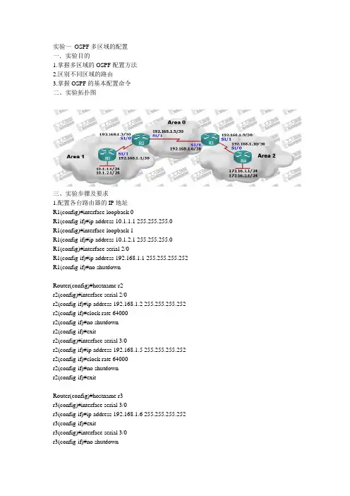
实验一OSPF多区域的配置一.实验目的1.掌握多区域的OSPF配置方法2.区别不同区域的路由3.掌握OSPF的基本配置命令二、实验拓扑图三、实验步骤及要求1.配置各台路由器的IP地址R1(config)#interface loopback 0R1(config-if)#ip address 10.1.1.1 255.255.255.0R1(config)#interface loopback 1R1(config-if)#ip address 10.1.2.1 255.255.255.0R1(config)#interface serial 2/0R1(config-if)#ip address 192.168.1.1 255.255.255.252 R1(config-if)#no shutdownRouter(config)#hostname r2r2(config)#interface serial 2/0r2(config-if)#ip address 192.168.1.2 255.255.255.252 r2(config-if)#clock rate 64000r2(config-if)#no shutdownr2(config-if)#exitr2(config)#interface serial 3/0r2(config-if)#ip address 192.168.1.5 255.255.255.252 r2(config-if)#clock rate 64000r2(config-if)#no shutdownr2(config-if)#exitRouter(config)#hostname r3r3(config)#interface serial 3/0r3(config-if)#ip address 192.168.1.6 255.255.255.252 r3(config-if)#exitr3(config)#interface serial 3/0r3(config-if)#no shutdownr3(config)#interface serial 2/0r3(config-if)#ip address 192.168.1.9 255.255.255.252r3(config-if)#clock rate 64000r3(config-if)#no shutdownRouter(config)#hostname r4r4(config)#interface serial 2/0r4(config-if)#ip address 192.168.1.10 255.255.255.252r4(config-if)#no shutdownr4(config-if)#exitr4(config)#interface loopback 0r4(config-if)#ip address 172.16.1.1 255.255.255.0r4(config-if)#exitr4(config)#interface loopback 1r4(config-if)#ip address 172.16.2.1 255.255.255.02.在r1上进行area1区域OSPF配置Router(config)#hostname r1r1(config)#router ospf 1r1(config-router)#network 10.1.2.0 0.0.0.255 area 1r1(config-router)#network 10.1.1.0 0.0.0.255 area 1r1(config-router)#network 192.168.1.0 0.0.0.3 area 1r1(config-router)#exit3.在r2上进行area1与area0的区域边界路由器(ABR)的OSPF配置r2(config)#router ospf 1r2(config-router)#network 192.168.1.0 0.0.0.3 area 1r2(config-router)#network 192.168.1.4 0.0.0.3 area 0r2(config-router)#exit4. 在r4上进行area2区域OSPF配置r4(config)#router ospf 1r4(config-router)#network 172.16.1.0 0.0.0.255 area 2r4(config-router)#network 172.16.2.0 0.0.0.255 area 2r4(config-router)#network 192.168.1.8 0.0.0.3 area 2r4(config-router)#exit在r3上进行area2与area0的区域边界路由器(ABR)的OSPF配置r3(config)#router ospf 1r3(config-router)#network 192.168.1.8 0.0.0.3 area 2r3(config-router)#network 192.168.1.4 0.0.0.3 area 0r3(config-router)#exit5. 在任一路由器上查看OSPF邻居表r2#show ip ospf neighborNeighbor ID Pri State Dead Time Address Interface 10.1.2.1 0 FULL/ - 00:00:38 192.168.1.1 Serial2/0 192.168.1.9 0 FULL/ - 00:00:39 192.168.1.6 Serial3/0R2路由器已经成功与r1和r3路由器建立邻居关系6.查看r1的路由表,观察其他区域的路由r1#show ip routeCodes: C - connected, S - static, I - IGRP, R - RIP, M - mobile, B - BGPD - EIGRP, EX - EIGRP external, O - OSPF, IA - OSPF inter areaN1 - OSPF NSSA external type 1, N2 - OSPF NSSA external type 2E1 - OSPF external type 1, E2 - OSPF external type 2, E - EGPi - IS-IS, L1 - IS-IS level-1, L2 - IS-IS level-2, ia - IS-IS inter area* - candidate default, U - per-user static route, o - ODRP - periodic downloaded static routeGateway of last resort is not set10.0.0.0/24 is subnetted, 2 subnetsC 10.1.1.0 is directly connected, Loopback0C 10.1.2.0 is directly connected, Loopback1172.16.0.0/32 is subnetted, 2 subnetsO IA 172.16.1.1 [110/2344] via 192.168.1.2, 00:00:05, Serial2/0O IA 172.16.2.1 [110/2344] via 192.168.1.2, 00:00:05, Serial2/0192.168.1.0/30 is subnetted, 3 subnetsC 192.168.1.0 is directly connected, Serial2/0O IA 192.168.1.4 [110/1562] via 192.168.1.2, 00:00:05, Serial2/0O IA 192.168.1.8 [110/2343] via 192.168.1.2, 00:00:05, Serial2/07.查看r1的OSPF链路状态数据库r1#show ip ospf databaseOSPF Router with ID (10.1.2.1) (Process ID 1)Router Link States (Area 1)Link ID ADV Router Age Seq# Checksum Link count 10.1.2.1 10.1.2.1 310 0x80000007 0x00463f 4192.168.1.5 192.168.1.5 310 0x80000006 0x00164a 2Summary Net Link States (Area 1)Link ID ADV Router Age Seq# Checksum192.168.1.4 192.168.1.5 845 0x80000001 0x00fe75192.168.1.8 192.168.1.5 518 0x80000002 0x0072ec172.16.1.1 192.168.1.5 518 0x80000003 0x00fe0f8.在r1上使用ping命令确认路由的有效性r1#ping 172.16.1.1Type escape sequence to abort.Sending 5, 100-byte ICMP Echos to 172.16.1.1, timeout is 2 seconds:!!!!!Success rate is 100 percent (5/5), round-trip min/avg/max = 78/87/94 ms9.查看r4的路由表和ospf的链路状态数据库r4#show ip routeCodes: C - connected, S - static, I - IGRP, R - RIP, M - mobile, B - BGPD - EIGRP, EX - EIGRP external, O - OSPF, IA - OSPF inter areaN1 - OSPF NSSA external type 1, N2 - OSPF NSSA external type 2E1 - OSPF external type 1, E2 - OSPF external type 2, E - EGPi - IS-IS, L1 - IS-IS level-1, L2 - IS-IS level-2, ia - IS-IS inter area* - candidate default, U - per-user static route, o - ODRP - periodic downloaded static routeGateway of last resort is not set10.0.0.0/32 is subnetted, 2 subnetsO IA 10.1.1.1 [110/2344] via 192.168.1.9, 00:23:31, Serial2/0O IA 10.1.2.1 [110/2344] via 192.168.1.9, 00:23:31, Serial2/0172.16.0.0/24 is subnetted, 2 subnetsC 172.16.1.0 is directly connected, Loopback0C 172.16.2.0 is directly connected, Loopback1192.168.1.0/30 is subnetted, 3 subnetsO IA 192.168.1.0 [110/2343] via 192.168.1.9, 00:23:41, Serial2/0O IA 192.168.1.4 [110/1562] via 192.168.1.9, 00:27:24, Serial2/0C 192.168.1.8 is directly connected, Serial2/0r4#show ip ospf databaseOSPF Router with ID (172.16.2.1) (Process ID 1)Router Link States (Area 2)Link ID ADV Router Age Seq# Checksum Link count 172.16.2.1 172.16.2.1 34 0x80000005 0x00feff 4192.168.1.9 192.168.1.9 14 0x80000004 0x00feff 2Summary Net Link States (Area 2)Link ID ADV Router Age Seq# Checksum192.168.1.0 192.168.1.9 1590 0x80000005 0x00a4bb10.1.1.1 192.168.1.9 1580 0x80000007 0x00d5e1 192.168.1.4 192.168.1.9 9 0x80000008 0x00f206。
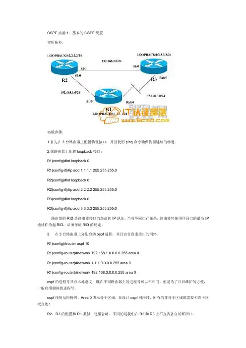
OSPF实验1:基本的OSPF配置实验拓扑:实验步骤:1.首先在3台路由器上配置物理接口,并且使用ping命令确保物理链路的畅通。
2.在路由器上配置loopback接口:R1(config)#int loopback 0R1(config-if)#ip add 1.1.1.1 255.255.255.0R2(config)#int loopback 0R2(config-if)#ip add 2.2.2.2 255.255.255.0R3(config)#int loopback 0R3(config-if)#ip add 3.3.3.3 255.255.255.0路由器的RID是路由器接口的最高的IP地址,当有环回口存在是,路由器将使用环回口的最高IP 地址作为起RID,从而保证RID的稳定。
3.在3台路由器上分别启动ospf进程,并且宣告直连接口的网络。
R1(config)#router ospf 10R1(config-router)#network 192.168.1.0 0.0.0.255 area 0R1(config-router)#network 1.1.1.0 0.0.0.255 area 0R1(config-router)#network 192.168.3.0.0.0.255 area 0ospf的进程号只有本地意义,既在不同路由器上的进程号可以不相同。
但是为了日后维护的方便,一般启用相同的进程号。
ospf使用反向掩码。
Area 0表示骨干区域,在设计ospf网络时,所有的非骨干区域都需要和骨干区域直连!R2,R3的配置和R1类似,这里省略。
不同的是我们在R2和R3上不宣告各自的环回口。
*Aug 13 17:58:51.411: %OSPF-5-ADJCHG: Process 10, Nbr 2.2.2.2 on Serial1/0 from LOADING to FULL, Loading Done配置结束后,我们可以看到邻居关系已经到达FULL状态。
实验目的:1)理解ospf的区域分层设计2)Ospf的配置3)Router-id的选择过程4)Ospf的dr和dbr选举配置5)Ospf的路由查看,邻居关系查看基本配置:R1:interface FastEthernet0/0ip address 10.1.1.1 255.255.255.0router ospf 1//1是进程号,是区分不同的ospf进程的,本地意义,不同的路由器可以可配置不同的号码network 10.1.1.1 0.0.0.0 area 0//0.0.0.0 表示精确的发布这个接口R2:interface Loopback0ip address 2.2.2.2 255.255.255.0!interface FastEthernet0/0ip address 10.1.1.2 255.255.255.0router ospf 1network 2.2.2.2 0.0.0.0 area 0network 10.1.1.2 0.0.0.0 area 0R3:interface Loopback0ip address 3.3.3.3 255.255.255.0!interface FastEthernet0/0ip address 10.1.1.3 255.255.255.0router ospf 1network 3.3.3.0 0.0.0.255 area 0network 10.1.1.0 0.0.0.255 area 0//0.0.0.255,表示发布的x.x.x.a,a表示任何子网地址,只要在这个子网地址范围内,都将被发布出去,本实验中是没有意义的,主类网段都不一样R4:(abr,area border router)interface Loopback0ip address 4.4.4.4 255.255.255.0!interface FastEthernet0/0ip address 10.1.1.4 255.255.255.0interface Serial1/0ip address 20.1.1.4 255.255.255.0network 4.4.4.4 0.0.0.0 area 0network 10.1.1.4 0.0.0.0 area 0network 20.1.1.4 0.0.0.0 area 1//因为r4是abr(区域边界路由器),不同的接口应该划在不同的区域中R5:interface Loopback0ip address 5.5.5.5 255.255.255.0ip ospf 1 area 1 前面的1是进程号,后面的1是区域号//是ospf另外一种发布接口的方法interface Serial1/0ip address 20.1.1.5 255.255.255.0ip ospf 1 area 1router ospf 1可以在r4上看一下ospf的邻居关系R4上应该有4个邻居关系Show ip ospf neighborrouter-idRouter-id 的作用?1. 标识路由器,用router-id来区分不同的路由器的链路状态数据库2. 类似于人的名字(身份证号码)3. Router-id如果规划好了,对路由器的识别就很容易。
OSPF -LSA实验目的:1、配置ospf多区域。
2、熟悉OSPF中1-5类LSA的传播环境、通告者以及传播的内容。
实验拓扑:实验步骤:R2R2(config)#interface f0/0R2(config-if)#ip address 10.1.1.2 255.255.255.252R2(config-if)#no shutR2(config-if)#exitR2(config)#interface s1/0R2(config-if)#ip address 11.1.1.1 255.255.255.252R2(config-if)#no shutR2(config-if)#exitR2(config)#interface l0R2(config-if)#ip address 2.2.2.2 255.255.255.0R2(config-if)#exitR2(config)#router ospf 110R2(config-router)#router-id 22.22.22.22R2(config-router)#network 10.1.1.0 0.0.0.3 area 1R2(config-router)#network 11.1.1.0 0.0.0.3 area 0R2(config-router)#network 2.2.2.0 0.0.0.255 area 0R2(config-router)#exitR2(config)#^ZR2#wrBuilding configuration...*Mar 1 01:42:16.147: %SYS-5-CONFIG_I: Configured from console by console[OK]R3R3(config)#interface s0/0R3(config-if)#ip address 11.1.1.2 255.255.255.252R3(config-if)#no shutR3(config-if)#exitR3(config)#interface s0/1R3(config-if)#ip address 12.1.1.1 255.255.255.252R3(config-if)#no shutR3(config-if)#exitR3(config)#interface l0R3(config-if)#ip address 3.3.3.3 255.255.255.0R3(config-if)#exitR3(config)#router ospf 110R3(config-router)#router-id 33.33.33.33R3(config-router)#network 3.3.3.0 0.0.0.255 area 0R3(config-router)#network 11.1.1.0 0.0.0.3 area 0R3(config-router)#network 12.1.1.0 0.0.0.3 area 2R3(config-router)#exitR3(config)#^ZR3#wrBuilding configuration...[OK]此时R3的ospf数据库中区域0有1类和3类,区域2有1类。
在思科模拟器中OSPF怎样设定思科模拟器怎么配置四个路由器四个区域OSPF100在思科模bai拟器中ospf设定的du步骤如下:zhi1、router1的dao配置版;配置环回口和int2/0的介面的ip地址和ospf的配置。
2、权router2的配置;配置环回口和int2/0的介面的ip地址和ospf的配置。
以及int2/0 的时脉频率。
3、router3的配置;配置环回口和int3/0的介面的ip地址和ospf 的配置。
以及int3/0 的时脉频率。
4、以router3为例,show??ip ospf inte***ce,此命令可以显示路由器的介面状态,如区域号、路由器的id、网路型别、介面成本。
5、以router 3为例。
通过show ?ip router命令,显示路由的情况,设定完成这样问题就解决了。
enable 进入特权复模式configuration terminal 进入配置模式router ospf xx(进位制程号,随意就一个bai标示)du 进入路由zhi模式***work x.x.x.x x.x.x.x area 0 宣告网路show ip ospf neighbor 检视daoospf邻居关系show ip route protocol ospf 检视ospf路由买本ospf的书看看,有点复杂思科模拟器怎么配置四个路由器四个区域ospf100把中间路由器的的四个介面的ip网段在ospf的程序下宣告到area 0区域。
把其他四个路由器连线中间路由器的埠的网段地址也宣告到area 0中。
剩下4个loopback介面的网段地址按图分别宣告到不同的area中就可以了这个只要做一个中心型的网路即可,中心是一个公共区域0,其他3个路由器其他介面连线交换机或pc机组成各个非骨干区域。
拓扑图如下:用思科模拟器怎么配置这个图多区域ospf ,求大神把中间路由器的的四个介面的ip网段在ospf的程序下宣告到area 0区域。
实验需求如上图,本实验结合真实案例,用来检验学员对OSPF协议的掌握情况R5为A公司总部网关,R2和R4分别是一号楼和二号楼的核心交换机,这里用路由器模拟,R1和R3分别为一号楼和二号楼的分发层交换机,这里也是用路由器模拟,每一栋楼是一个ospf区域,包含着诺干个vlan,核心交换机和网关之间是骨干区域。
R6是A公司分公司网关,和总部通过帧中继互联,R7是分部核心交换机,分部的ospf是区域3,因为分部业务扩展,合并了B公司(R8,R9),B公司原来是ospf区域4。
1.根据上图,搭建好拓扑,ISP用一台路由器模拟,服务器和PC机全部采用回环口模拟2.配置好帧中继环境,要求帧中继不能动态获取映射,也不能静态配置映射,配置好IP地址,测试直连PING通3.依据上图,配置好OSPF协议,验证邻居建立4.确保整个内网全网可达5.确保骨干区域邻居建立高安全性6.尽量减小网关的路由表条目7.R1,R3,R9性能不足,尽量减少其路由表条目实验步骤1、对各路由器配置IP地址2、将R10模拟为帧中继R10#conf tR10(config)#frame-relay swiR10(config)#frame-relay switchingR10(config)#int s0/0R10(config-if)#no shutR10(config-if)#encapsulation frame-relayR10(config-if)#frame-relay intf-type dceR10(config-if)#clock rate 64000R10(config-if)#frame-relay route 506 int s0/1 605R10(config-if)#int s0/1R10(config-if)#encapsulation frame-relayR10(config-if)#frame-relay intf-type dceR10(config-if)#clock rate 64000R10(config-if)#frame-relay route 605 int s0/0 506R10(config-if)#exit在R5的s2/0,及R6的s1/0做相应的帧中继封装R5(config)#int s2/0R5(config-if)#encapsulation frame-relayR5(config-if)#frame-relay intf-type dteR5(config-if)#exitR6(config)#int s1/0R6(config-if)#encapsulation frame-relayR6(config-if)#frame-relay intf-type dteR6(config-if)#exit3、配置OSPF协议,并验证邻居建立R1(config)#router ospf 1R1(config-router)#router-idR1(config-router)#router-id 1.1.1.1R1(config-router)#net 172.16.3.1 0.0.0.0 a 1R1(config-router)#exit其他路由器的配置命令类似在R10帧中继线路上,R5的接口s2/0与R6接口s1/0的OSPF类型为非广播因此不能产生Hello包以建立OSPF邻居。
多区域下OSPF 配置实验
一.实验目的:
将大型网络划分多个OSPF 区域,掌握多区域下OSPF 的配置。
二.实验要点:
1.OSPF 多区域的划分
2.OSPF 路由条目。
三.实验设备:
Cisco 2621路由器4 台
四、实验环境
区域0
RouterA RouterB
F0/1 172.16.0.1/16
F0/1 192.168.0.1/24
F0/1 172.16.0.2/16 F0/1 192.168.0.2/24
RouterC RouterD
F0/0 172.17.0.1/16
F0/0 192.168.1.1/24
区域1
区域2
图12 多区域下OSPF 的配置
五. 实验步骤
1.按图12连接各路由器。
2.按图121配置各路由器的IP地址等参数。
3.配置路由器RouterA 、RouterB、RouterC和RouterD上的OSPF协议。
RouterA(config)#router ospf 1
RouterA(config-router)#net 10.0.0.0 0.255.255.255 area 0
RouterA(config-router)#net 172.16.0.0 0.0.255.255 area 1
-
.测试各网络之间的连通性。
5.观察各路由器的路由表条目。
5.练习OSPF 的各种诊断命令对OSPF 的运行进行诊断,观察诊断输出。
六. 实验总结
1.多区域OSPF 配置与单区域OSPF 配置的区别?。
思科Cisco路由器配置——使⽤OSPF协议实现的全⽹互通配置实验详解本⽂实例讲述了思科Cisco使⽤OSPF协议实现的全⽹互通配置实验。
分享给⼤家供⼤家参考,具体如下:⼀、实验⽬的:⽤OSPF协议使全⽹互通⼆、拓扑图三、具体步骤配置(1)R1路由器配置Router>enableRouter#configure terminalEnter configuration commands, one per line. End with CNTL/Z.Router(config)#hostname R1R1(config)#interface f0/0R1(config-if)#ip address 192.168.1.2 255.255.255.0R1(config-if)#no shutdownR1(config-if)#interface s0/0/0R1(config-if)#ip address 10.1.1.1 255.255.255.0R1(config-if)#clock rate 64000R1(config-if)#no shutdownR1(config-if)#interface s0/0/1R1(config-if)#ip address 30.1.1.1 255.255.255.0R1(config-if)#clock rate 64000This command applies only to DCE interfacesR1(config-if)#no shutdownR1(config-if)#exitR1(config)#router ospf 1R1(config-router)#router-id 1.1.1.1R1(config-router)#network 192.168.1.0 0.0.0.255 area 0R1(config-router)#network 10.1.1.0 0.0.0.255 area 0R1(config-router)#network 30.1.1.0 0.0.0.255 area 0R1(config-router)#end(2)R2路由器配置Router>enableRouter#configure terminalEnter configuration commands, one per line. End with CNTL/Z.Router(config)#hostname R2R2(config)#interface f0/0R2(config-if)#ip address 192.168.2.2 255.255.255.0R2(config-if)#no shutdownR2(config-if)#interface s0/0/0R2(config-if)#ip address 20.1.1.1 255.255.255.0R2(config-if)#clock rate 64000R2(config-if)#no shutdownR2(config-if)#interface s0/0/1R2(config-if)#ip address 10.1.1.2 255.255.255.0R2(config-if)#clock rate 64000This command applies only to DCE interfacesR2(config-if)#no shutdown%LINK-5-CHANGED: Interface Serial0/0/1, changed state to downR2(config-if)#exitR2(config)#router ospf 1R2(config-router)#router-id 2.2.2.2R2(config-router)#network 192.168.2.0 0.0.0.255 area 0R2(config-router)#network 20.1.1.0 0.0.0.255 area 0R2(config-router)#network 10.1.1.0 0.0.0.255 area 0R2(config-router)#end(3)R3路由器配置Router>enableRouter#configure terminalEnter configuration commands, one per line. End with CNTL/Z.Router(config)#hostname R3R3(config)#interface f0/0R3(config-if)#ip address 192.168.3.1 255.255.255.0R3(config-if)#no shutdownR3(config-if)#interface s0/0/0R3(config-if)#ip address 30.1.1.2 255.255.255.0R3(config-if)#clock rate 64000R3(config-if)#no shutdown%LINK-5-CHANGED: Interface Serial0/0/0, changed state to down R3(config-if)#interface s0/0/1R3(config-if)#ip address 20.1.1.2 255.255.255.0R3(config-if)#clock rate 64000This command applies only to DCE interfacesR3(config-if)#no shutdown%LINK-5-CHANGED: Interface Serial0/0/1, changed state to down R3(config-if)#exitR3(config)#router ospf 1R3(config-router)#router-id 3.3.3.3R3(config-router)#network 192.168.3.0 0.0.0.255 area 0R3(config-router)#network 30.1.1.0 0.0.0.255 area 0R3(config-router)#network 20.1.1.0 0.0.0.255 area 0R3(config-router)#end(4)R4路由器配置Router>enableRouter#configure terminalEnter configuration commands, one per line. End with CNTL/Z. Router(config)#hostname R4R4(config)#interface f0/0R4(config-if)#ip address 192.168.1.1 255.255.255.0R4(config-if)#no shutdownR4(config-if)#interface f0/1R4(config-if)#ip address 192.168.10.254 255.255.255.0R4(config-if)#no shutdownR4(config-if)#exitR4(config)#router ospf 1R4(config-router)#router-id 4.4.4.4R4(config-router)#network 192.168.1.0 0.0.0.255 area 0R4(config-router)#network 192.168.10.0 0.0.0.255 area 0R4(config-router)#end(5)R5路由器配置Router>enableRouter#configure terminalEnter configuration commands, one per line. End with CNTL/Z. Router(config)#hostname R5R5(config)#interface f0/0R5(config-if)#ip address 192.168.3.2 255.255.255.0R5(config-if)#no shutdownR5(config-if)#interface f0/1R5(config-if)#ip address 192.168.30.254 255.255.255.0R5(config-if)#no shutdownR5(config-if)#exitR5(config)#router ospf 1R5(config-router)#router-id 5.5.5.5R5(config-router)#network 192.168.3.0 0.0.0.255 area 0R5(config-router)#network 192.168.30.0 0.0.0.255 area 0R5(config-router)#end(6)R6路由器配置Router>enableRouter#configure terminalEnter configuration commands, one per line. End with CNTL/Z. Router(config)#hostname R6R6(config)#interface f0/0R6(config-if)#ip address 192.168.2.1 255.255.255.0R6(config-if)#no shutdownR6(config-if)#interface f0/1R6(config-if)#ip address 192.168.20.254 255.255.255.0R6(config-if)#no shutdownR6(config-if)#exitR6(config)#router ospf 1R6(config-router)#router-id 6.6.6.6R6(config-router)#network 192.168.2.0 0.0.0.255 area 0R6(config-router)#network 192.168.20.0 0.0.0.255 area 0R6(config-router)#end四、验证测试1、查看R1路由表信息2、查看ip路由协议配置与统计信息3、查看OSPF数据库信息4、查看OSPF进程及区域的细节。