MIE-5428 自愈环以太网光纤交换机
- 格式:pdf
- 大小:107.96 KB
- 文档页数:3
工业快速以太网交换机一.MIEN2200系列导轨式非网管工业以太网交换机(新)二.MIEN3208系列导轨式非网管冗余工业以太网交换机 三.MIEN5208系列导轨式网管冗余工业以太网交换机 四.MIEN2000系列机架式非网管工业以太网交换机五、MIEN6000系列机架式WEB网管工业以太网交换机(新)六、MIEN6200系列导轨式WEB网管工业以太网交换机(新)2010年1月一. M IEN2200系列导轨式工业以太网交换机(一)价目表型号百兆光口百兆电口基本型价格(单模)结构供货时间MIEN2203 1 2 1180.00 小导轨外壳2010-01-31MIEN2206 2 4 1980.00 小导轨外壳2010-01-31MIEN2207 1 6 1580.00 小导轨外壳2010-01-31MIEN2208 8 1080.00 小导轨外壳2010-01-31MIEN2213 1 12 2180.00 中导轨外壳2010-01-31MIEN2214 2 12 2780.00 中导轨外壳2010-03-31MIEN2212 4 8 3980.00 中导轨外壳2010-03-31MIEN2210 6 4 4580.00 中导轨外壳2010-03-31MIEN2216 16 2080.00 中导轨外壳2010-04-31(二)价目表说明1、以上报价如含光口,基本型指单模SC、20公里光接口。
多模SC/5Km光接口,每一个光接口比单模报价降低100元;例如MIEN2203基本型(SC,20公里)报价为1080元,如果选用1个多模SC光接口,价格为980元。
2、40公里光模块比20公里光模块报价增加400元,60公里光模块报价比20公里增加2800元,80公里及以上的光模块报价比20公里增加6000元。
3、如果选用ST或SC光接口,每个光口最终成交价比SC型增加15元。
4、以上基本型产品均指9~30V直流供电,支持双电源备份,带掉电报警触点;如选择DC-48V供电,最终成交价增加50元,支持双电源备份,带掉电报警触点;选择AC220V或DC220V供电,最终成交价增加80元,只能单电源供电,带掉电报警触点。
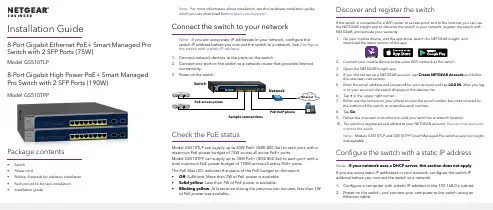
Installation Guide8-Port Gigabit Ethernet PoE+ Smart Managed Pro Switch with 2 SFP Ports (75W)Model GS510TLP8-Port Gigabit High Power PoE+ Smart Managed Pro Switch with 2 SFP Ports (190W)Model GS510TPPPackage contents• Switch• Power cord• Rubber footpads for tabletop installation• Rack-mount kit for rack installation• Installation guideNote: For more information about installation, see the hardware installation guide, which you can download from /support/.Connect the switch to your networkNote: If you are using static IP addresses in your network, configure theswitch IP address before you connect the switch to a network. See Configure the switch with a static IP address.1. Connect network devices to the ports on the switch.2. Connect one port on the switch to a network router that provides Internetconnectivity.Check the PoE statusModel GS510TLP can supply up to 30W PoE+ (IEEE 802.3at) to each port, with amaximum PoE power budget of 75W across all active PoE+ ports.Model GS510TPP can supply up to 30W PoE+ (IEEE 802.3at) to each port, with atotal maximum PoE power budget of 190W across all active PoE+ ports.The PoE Max LED indicates the status of the PoE budget on the switch:• Off. Sufficient. More than 7W of PoE power is available.• Solid yellow. Less than 7W of PoE power is available.• Blinking yellow. At least once during the previous two minutes, less than 7Wof PoE power was available.Discover and register the switchIf the switch is connected to a WiFi router or access point and to the Internet, you can usethe NETGEAR Insight app to discover the switch in your network, register the switch withNETGEAR, and activate your warranty.1. On your mobile device, visit the app store, search for NETGEAR Insight, anddownload the latest version of the app.2. Connect your mobile device to the same WiFi network as the switch.3. Open the NETGEAR Insight app.4. If you did not set up a NETGEAR account, tap Create NETGEAR Account and followthe onscreen instructions.5. Enter the email address and password for your account and tap LOG IN. After you login to your account, the switch displays in the devices list.6. Tap + in the upper right corner.7. Either use the camera on your phone to scan the serial number bar code located onthe bottom of the switch, or enter the serial number.8. Tap Go.9. Follow the onscreen instructions to add your switch to a network location.10. The switch is registered and added to your NETGEAR account. You can now view andmonitor the switch.Note: Models GS510TLP and GS510TPP Smart Managed Pro switches are not Insightmanageable.Configure the switch with a static IP addressNote: If your network uses a DHCP server, this section does not apply.If you are using static IP addresses in your network, configure the switch IPaddress before you connect the switch to a network.1. Configure a computer with a static IP address in the 192.168.0.x subnet.2. Power on the switch, and connect your computer to the switch using anEthernet cable.NETGEAR, Inc.350 East Plumeria DriveSan Jose, CA 95134, USANETGEAR INTERNATIONAL LTD Floor 1, Building 3University Technology Centre Curraheen Road, Cork, T12EF21, Ireland© NETGEAR, Inc., NETGEAR and the NETGEAR Logoare trademarks of NETGEAR, Inc. Any non‑NETGEARtrademarks are used for reference purposes only.SupportThank you for purchasing this NETGEAR product. You can visithttps:///support/ to register your product, get help, access the latest downloads and user manuals, and join our community. We recommend that you use only official NETGEAR support resources.Si ce produit est vendu au Canada, vous pouvez accéder à ce document en français canadien à https:///support/download/.(If this product is sold in Canada, you can access this document in Canadian French at https:///support/download/.)For regulatory compliance information including the EU Declaration of Conformity, visit https:///about/regulatory/.See the regulatory compliance document before connecting the power supply.Do not use this device outdoors. If you connect cables or devices that are outdoors to this device, see https:///000057103 for safety and warranty information.August 20193. Open a web browser and enter 192.168.0.239 in the address bar.(The default IP address of the switch is 192.168.0.239) A login page displays.4. Enter password for the password.The System Information page displays.5. Select System > Management > IP Configuration . Select the Static IPAddress radio button.6. Enter the static IP address, subnet mask, and default gateway IP address thatyou want to assign to the switch and click the Apply button.Your settings are saved.Configure the switchTo configure the switch either:• Use the local browser browser–based interface.• Install the NETGEAR Switch Discovery Tool on your Mac or a 64-bit Windows-based computer.•Install the Smart Control Center utility on your Windows-based computer.Access the local browser interface1. For initial configuration, open a web browser on a computer that is on thesame network and subnet as the switch and enter the switch’s IP address.If you are unsure how to determine the IP address of the switch, you can use the Smart Control Center utility.2. A login page displays. Enter password for the password.The System Information page displays.3. Configure the switch for your network.For information about switch configuration, see the user manual for your switch, which you can download from /support/.Other discovery and configuration methodsThe NETGEAR Switch Discovery Tool and the Smart Control Center utility let you discover the IP address and configure the switch. •NETGEAR Switch Discovery Tool . You can use a Mac or a 64-bit Windows-based computer on the same network as the switch. To download this tool, visit /support/product/netgear-switch-discovery-tool.aspx.•Smart Control Center utility . You can use a Windows-based computer on the same network as the switch. To download this utility, visit /support/product/SCC .Troubleshooting tipsHere are some tips for correcting simple problems that might occur.•Be sure to power on your computer and switch in the following sequence:a. Turn on the switch and wait about two minutes.b. Turn on the computer and connect it to the switch.•Make sure the Ethernet cables are plugged in.For each powered-on computer connected to the switch, the corresponding switch LAN port status LED is lit.•Make sure the network settings of the computer are correct.In most cases, computers should be configured to obtain an IP addressthrough DHCP . If your network uses static IP addresses, be sure that the switch and computer are configured with valid IP addresses. For more i nformation, see the user manual.。
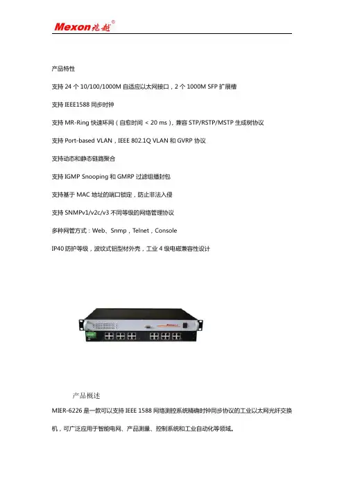
产品特性支持24个10/100/1000M自适应以太网接口,2个1000M SFP扩展槽支持IEEE1588同步时钟支持MR-Ring快速环网(自愈时间<20ms),兼容STP/RSTP/MSTP生成树协议支持Port-based VLAN,IEEE802.1Q VLAN和GVRP协议支持动态和静态链路聚合支持IGMP Snooping和GMRP过滤组播封包支持基于MAC地址的端口锁定,防止非法入侵支持SNMPv1/v2c/v3不同等级的网络管理协议多种网管方式:Web、Snmp,Telnet,ConsoleIP40防护等级,波纹式铝型材外壳,工业4级电磁兼容性设计产品概述MIER-6226是一款可以支持IEEE1588网络测控系统精确时钟同步协议的工业以太网光纤交换机,可广泛应用于智能电网、产品测量、控制系统和工业自动化等领域。
MIER-6226可提供24个1000M端口和2个1000M SFP插槽,其中24个1000M端口可根据用户现场需要配置为光口或电口,极大地方便了用户的现场使用。
MIER-6226工业以太网交换机支持MR-Ring自愈环系统及RSTP功能,全负载下故障恢复时间<20ms,并可组建链形、环形等各种光纤冗余网络。
MIER-6226系列同时提供全面的网管功能,基于端口的VLAN、基于802.1Q的VLAN、QOS、IGMP Snooping、RSTP、广播风暴抑制、端口聚合、端口镜像、端口状态管理、SNMP、NTP对时等,可完全满足用户的网管需求。
1.支持IEEE1588网络测控系统精确时钟同步协议,同步精度可达±100ns2.网络支持MR-Ringredundancy;冗余功能;恢复时间<20毫秒3.IEEE802.1w快速生成树协议,IEEE802.1S MSTP和IEEE802.1D STP兼容4.IGMP Snooping组播功能5.支持基于端口的VLAN和IEEE802.1Q VLAN标记和GVRP6.IEEE802.1pQoS优先级控制7.基于MAC地址的自动连接中继故障切换8.RS-232控制台、Telne、SNMP、Web浏览器和TFTP管理9.支持IEEE802.1x安全10.端口速率控制11.静态安全的每端口MAC地址12.端口镜像13.支持端口聚合,支持IEEE802.3ad,3条聚合链路组14.10/100Mbps-Full/Half-duplex,自动协商,Auto-MDI/MDIX15.全线速转发速率16.支持NTP对时系统产品参数属性MIER-6226接口24个10/100/1000M自适应以太网接口2个1000M SFP扩展槽网线类型和距离双绞线,支持最大传输距离100m光口属性单模1310nm,多模850nm;单模20km,多模550m(长距离模块可定制)处理类型存储转发MAC地址表大小支持8K个MAC地址支持黑洞MAC地址支持设置端口MAC地址学习最大个数支持静态组播MAC背板带宽52Gbps 包转发速率9.6Mpps 包缓存12Mbit流量控制支持IEEE802.3x流量控制(全双工)支持基于端口速率百分比的风暴抑制支持基于PPS的风暴抑制环网冗余协议支持MR-ring协议(自愈时间<20ms)生成树协议支持STP/RSTP/MSTP协议支持STP Root Guard支持BPDU GuardVLAN 支持基于端口的VLAN(4094个),802.1Q的VLAN 支持GVRP自愈环组网方式支持多组自愈环支持相切环链路聚合支持静态聚合、动态聚合Jumbo Frame巨帧支持,最大帧长为9KDHCP支持DHCP Client广播/组播/单播风暴抑制支持基于端口速率百分比的风暴抑制组播支持IGMP SnoopingQoS 支持对端口接收报文的速率和发送报文的速率进行限制,粒度为:8Kbit/s每个端口支持8个输出队列支持灵活的队列调度算法,可以同时基于端口和队列进行设置,支持SP、WRR、SP+WRRACL 提供基于源MAC地址、目的MAC地址、源IP(IPv4)地址、目的IP(IPv4)地址、TCP/UDP端口号的访问控制策略支持入方向ACL策略端口镜像支持端口镜像网络安全支持用户分级管理和口令保护支持AAA认证支持RADIUS认证支持端口隔离802.1X支持基于端口的认证和基于MAC的认证升级和配置支持FTP/TFTP/WEB升级,日志记录,配置文件下载与上传告警输出支持电源告警管理支持命令行接口(CLI)配置支持Telnet远程配置支持通过Console口配置支持SNMP维护支持Ping支持Telnet远程维护指示灯电源指示:POW,接口灯指示:LINK/ACT电源输入电压:AC/DC85~265V 最大功耗:19.8W支持电源防反接保护工业凤凰端子接线工作环境工作温度:-40℃~+75℃储存温度:-40℃~85℃相对湿度:5%~95%无凝露安装方式1U机架式安装外形尺寸宽×高×深:482.6mm×44mm×280mm 防护等级IP40防护等级,无风扇设计MTBF350000h质保期5年符合标准IEEE802.3:CSMA/CDIEEE802.3i:10Base-TIEEE802.3u:100Base-TIEEE802.3ad:链路聚合IEEE802.3x:全双工以太网数据链路层流控IEEE 802.1p:流量优先级IEEE802.1Q:VLAN IEEE 802.1w:快速生成树IEEE 802.1X:基于端口的网络访问控制EMI 电磁干扰度测试EMC IEC61000-4-2(ESD)±8kV(contact),±15kV(air)IEC61000-4-3(RS)10V/m(80MHz~2GHz)IEC61000-4-4(EFT)Power Port:±4kV;Data Port:±2kVIEC61000-4-5(Surge)Power Port:±2kV/DM,±4kV/CM;Data Port:±2kVIEC61000-4-6(CS)3V(10kHz~150kHz);10V(150kHz~80MHz)IEC61000-4-16(共模传导)30V(cont.),300V(1s)安装图示订货信息产品型号规格参数MIER-622624个10/100/1000M 电口,支持网管MIER-6226-GX224个10/100/1000M电口,2个1000M SFP扩展槽,支持网管MIER-6226-GX1212个10/100M电口,12个1000M SFP扩展槽,支持网管可选配件产品型号规格说明1GSFP模块ME-S2101SFP with10M/100M/1000M(RJ-45)ME-S2118-S SFP1.25G/1.0625G、850nm LC550mME-S2123-S SFP1.25G/1.0625G、1310nm LC20kmME-S2123-S40SFP1.25G/1.0625G、1310nm LC40kmME-S2125-S80SFP1.25G/1.0625G、1550nm LC80kmME-S2123S-S SFP1.25G/1.0625G、1310nm单纤LC20km ME-S2123S-S40SFP1.25G/1.0625G、1310nm单纤LC40km ME-S2125S-S80SFP1.25G/1.0625G、1550nm单纤LC80km上海兆越通讯技术有限公司创立于2003年,是国家科技部创新基金立项企业;公司致力于工业通信的产品研发与技术创新,专注于工业以太网通信、工业无线通信、现场总线、光纤通信、嵌入式通信,目前已成功推出数十条产品线、几百种产品,已成为国内工业通信领域的品牌。


光纤交换机配置谈起交换机本地配置,首先我们来看一下交换机的物理连接。
交换机的本地配置方式是通过计算机与交换机的“Console”端口直接连接的方式进行通信的。
下面是店铺跟大家分享的是光纤交换机配置,欢迎大家来阅读学习。
光纤交换机配置工具/原料Windows电脑交换机第1步:1第1步:单击“开始”按钮,在“程序”菜单的“附件”选项中单击“超级终端”,弹出如图所示界面。
2第2步:双击“Hypertrm”图标,弹出如图所示对话框。
这个对话框是用来对立一个新的超级终端连接项。
3第3步:在“名称”文本框中键入需新建超的级终端连接项名称,这主要是为了便于识别,没有什么特殊要求,我们这里键入“Cisco”,如果您想为这个连接项选择一个自己喜欢的图标的话,您也可以在下图的图标栏中选择一个,然后单击“确定”按钮,弹出如图所示的对话框。
4第4步:在“连接时使用”下拉列表框中选择与交换机相连的计算机的串口。
单击“确定”按钮,弹出如图所示的对话框。
5第5步:在“波特率”下拉列表框中选择“9600”,因为这是串口的最高通信速率,其他各选项统统采用默认值。
单击“确定”按钮,如果通信正常的话就会出现类似于如下所示的主配置界面,并会在这个窗口中就会显示交换机的初始配置情况。
Catalyst 1900 Management ConsoleCopyright (c) Cisco Systems,Inc。
1993-1999All rights reserved。
Standard Edition SoftwareEthernet address:00-E0-1E-7E-B4-40PCA Number:73-2239-01PCA Serial Number:SAD01200001Model Number:WS-C1924-ASystem Serial Number:FAA01200001User Interface Menu[M] Menus//主配置菜单[I] IP Configuration//IP地址等配置[P] Console Password //控制密码配置Enter Selection://在此输入要选择项的快捷字母,然后按回车键确认至此就正式进入了交换机配置界面了,下面的工作就可以正式配置交换机了。
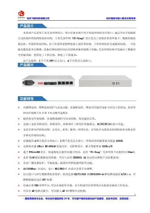
本系列产品采用工业冗余环网设计,每台设备有两个用于组成环网的光纤端口,通过手拉手的级联方式组成环形的网络拓扑结构,工业冗余环网(FC-Ring)设计是为了实现在恶劣环境下,数据传输的稳定性、可靠性和实时性。
其工作原理是物理连接上成环型结构,工作时网络信号成链状结构,一旦传输光缆某处节点断路,设备以极短的时间自动切换到备用线路上传输。
冗余环网结构不仅减少了数据信号传输风险,更简化了工程安装,降低了工程成本。
此产品提供:2个千兆SFP以太光口;4个百兆以太电接口。
内置锂电池,带锂电池保护与充电功能,设备断电时,锂电可以提供1-2小时以上的供电,保证环网光纤线路工作正常(本功能可选配);提供两光纤条线路,在线路故障时可自动切换,保证通信正常。
光接口支持多模双纤、单模双纤、单模单纤三种光纤传输模式,SC/ST/FC/LC接口可选;支持多种光纤网络结构:点对点、星型、链型、环网冗余,并可组合为更复杂的网络拓扑结构支持多种光纤网络结构;设备提供4路百兆以太网电口,2路千兆光以太接口,环网总的传输带宽为线速1000M;交换机内建1Mbit MP-SSRAM高速内存,无阻塞设计,最大背板带宽32GBit/S基于FPGA+ARM设计,快速缩短自愈环回建立时间,支持“FC-Ring”冗余环网(自愈时间<20ms); 支持VLAN超长数据包的传输,可以与支持IEEE802.1Q协议的交换机产品匹配使用;具有广播风暴保护、平衡流量、隔离冲突和检测差错等功能;10/100Mbps自适应,电口MDI/MDI-X自适应无需手动调整,以太接口与串行数据带防雷保护,防雷达到GB/T17626.5(IEC61000-4-5)短路电流波8/20μs,开路峰值输出电压6KV标准设备自带WEB管理平台,可以在线软件升级,在主机端可以管理每台从机的设备的工作状态;可以有4U机框式插卡,可以插入4U17槽集中式机框;宽温型:工作温度-40℃~+85℃多种电源方式可选:AC220V、DC-48V/DC+24V/DC+12V等◆光纤部分多模光纤:50/125um或62.5/125um,传输距离:2Km多模光纤,衰减(3dbm/km)波长:850nm发射功率:-12dBm(Min)~-9dBm(Max)接收灵敏度:-28dBm(Min)链路预算:16dBm单模光纤:8/125um或9/125um,传输距离:20Km单模光纤,衰减(0.35dbm/km)(实际如需更大距离需定制)波长:1310nm(超长距离传输时选用1550nm波长)发射功率:-9dBm(Min)~-5dBm(Max)接收灵敏度:-27dBm(Min)◆10/100M以太网接口协议:符合IEEE802.3,IEEE802.1Q(VLAN)速率:10/100M自适应,全/半双工完全自适应MAC地址表:可以学习8K MAC地址物理接口:RJ45座,支持Auto-MDIX(交叉/直通线自适应)◆电气和机械特性系统电源:冗余双电源输入DC9-48V/AC9-48V功耗:≤10W外观结构:133mm(长)x120mm(宽)x42.0mm(高)◆环境指标工作温度:-40℃—+85℃(工业级)储存温度:-40℃—+90℃产品型号FCRM-F4产品功能描述4*10/100M电口千兆光以环网交换机,SFP光模块,桌面式业务端口描述2个千兆以太光口,4个百兆电口电源AC220V或DC-48V(电源可选)产品尺寸(长×宽×高)216*138*31mm桌面式重量 1.1Kg/台本产品支持多种光纤网络拓扑结构:点对点通讯、链型网络、星型网络及冗余环网自愈保护等拓扑结构:本系列产品应用灵活,同时,该系列产品可采用双光口实现双纤环网冗余功能,当某处光纤故障时,系统会在20ms内重建网络链路,保障系统的正常通信,实现对总线信号传输的自愈保护功能,网络故障排除后系统会自动恢复。

施耐德电气公司水行业透明工厂工业以态网控制系统解决方案网络、现场控制器的特点透明工厂系统采用法国施耐德电气公司的自动化控制产品,包括现场控制器、远程I/O 控制单元和网络设备,组成适合隧道现场要求的自愈式光纤环网。
一.网络:∙透明工厂监控系统的现场控制骨干网 - 自愈式光纤环1.采用法国施耐德电气公司的光纤交换机499NOS17100构建自愈式光纤环网,能确保在出现一个网络断点的情况下自动恢复网络的连接,保证骨干网与上位监控系统的数据传输的可靠性。
2.介质采用62.5/125μm 多模光纤。
3.网络协议为国标GB/Z 19582.3 Ethernet Modbus TCP/IP,全开放的工业以太网,监控中心的计算机无需插专用以太网卡或专用接口软件即可接入,大大提高了网络透明性和开放性,也确保了网络兼容性和易于扩展。
4.通讯速率为100Mbps,全双工可达200Mbps。
5.各区域控制器采用法国施耐德电气公司的Quantum PLC和I/O模块,通过以太网模块,挂接在 Ethernet TCP/IP Modbus 骨干以太网的交换机上。
6.光纤交换机499NOS17100为工业级以太网交换机,10/100 Mbps自适应,支持全双工运行模式,电源采用冗余24VDC供电,确保供电可靠性,符合工业级认证标准。
7.光纤交换机499NOS17100支持采用多模光纤构建自愈式环网,技术要求为,环网上交换机数量小于50个,同时相邻交换机之间采用多模光纤连接的最大距离3100米。
8.光纤交换机499NOS17100支持冗余功能,可实现跨网冗余连接,切换时间小于500ms。
9.交换机支持SNMP技术,具有简单网管功能。
10.交换机具有Web-server内置功能,支持通过浏览器的网管和监视诊断功能,具有可视化的带宽监视功能。
二. 以太网通讯模块140 NOE77111∙Quantum的以太网通讯模块140 77111具有强大的功能。


P/N: 1802055240012*1802055240012*TN-5524-8PoE Quick Installation GuideMoxa ToughNet SwitchEdition 3.0, February 2017Technical Support Contact Information /support Moxa Americas:Toll-free: 1-888-669-2872Tel: 1-714-528-6777Fax: 1-714-528-6778 Moxa China (Shanghai office): Toll-free: 800-820-5036 Tel: +86-21-5258-9955 Fax: +86-21-5258-5505 Moxa Europe:Tel: +49-89-3 70 03 99-0Fax: +49-89-3 70 03 99-99 Moxa Asia-Pacific: Tel: +886-2-8919-1230 Fax: +886-2-8919-1231 Moxa India:Tel: +91-80-4172-9088Fax: +91-80-4132-10452017 Moxa Inc. All rights reserved.OverviewThe ToughNet TN-5524-8PoE series M12 managed Ethernet switches are designed for industrial applications in harsh environments. The TN series switches use M12 and other circular connectors to ensure tight, robust connections, and guarantee reliable operation against environmental disturbances, such as vibration and shock. The TN-5524-8PoE series switches provide 24 Fast Ethernet M12 ports, 8 of which are10/100BaseT(X) PoE compliant.TN-5524-8PoE switches provide up to 15.4 watts of power per PoE port, and allow power to be supplied to connected devices (such as surveillance cameras, wireless access points, and IP phones) when AC power is not readily available or is cost-prohibitive to provide locally. Models with an extended operating temperature range of -40 to 75°C are also available. The TN-5524-8PoE series Ethernet switches are compliant with mandatory sections of EN 50155, covering operating temperature, power input voltage, surge, ESD, and vibration, as well as conformal coating and power insulation, making the switches suitable for a variety of industrial applications.Package ChecklistYour ToughNet TN-5524-8PoE switch is shipped with the following items. If any of these items is missing or damaged, contact your customer service representative for assistance.• 1 Moxa ToughNet switch•M12 to DB9 console port cable• 2 protective caps for console and relay output ports•Panel mounting kit•CD-ROM with user’s manual, Windows utility, and SNMP MIB file •Quick installation guide (printed)•Warranty cardFeaturesAnti-Vibration Circular Connectors for Robust Links•M12 D-coding 4-pin female connectors for Fast Ethernet 10/100BaseT(X) ports•M12 A-coding 5-pin male connectors for console and relay output •M23 6-pin male connector for power inputIsolated Power Input•Supports 24 VDC (16.8 to 30 VDC), isolatedHigh Performance Network Switching Technology•IPv6 ready, certified by the IPv6 Logo Committee•IEEE 1588 PTP (Precision Time Protocol) for the precise time synchronization of networks•DHCP Option 82 for IP address assignment with different policies •Modbus/TCP industrial Ethernet protocol•Turbo Ring, Turbo Chain,and RSTP/STP (IEEE802.1w/D)•IGMP Snooping and GMRP for filtering multicast traffic from industrial Ethernet protocols•Port-based VLAN, IEEE802.1Q VLAN, and GVRP protocol to ease network planning•QoS (IEEE802.1p/1Q and TOS/DiffServ) to increase determinism•802.3ad, LACP for optimum bandwidth utilization•IEEE802.1X and https/SSL to enhance network security•SNMP v1/v2c/v3 for different levels of network management •RMON for efficient network monitoring and proactive capability •Bandwidth management prevents unpredictable network status •Lock port restricts access to authorized MAC addresses only •Port mirroring for online debugging•Automatic warning by exception through email, relay output •Automatic recovery of connected devices’ IP addresses•Line-swap fast recovery•LLDP for automatic topology discovery through network management software•Configurable through Web browser, Telnet/Serial console, and Windows utilityDesigned for Industry-specific Applications•Power failure, port break alarm by relay output•Complies with all EN 50155 mandatory test items*•-40 to 75°C operating temperature range (for “-T” models)•IP40, rugged high-strength housing•Panel mounting mounting installation capability*This product is suitable for rolling stock railway applications, as defined by the EN 50155 standard. For a more detailed statement, click here: /doc/specs/EN_50155_Compliance.pdf Recommended Optional Accessories•CBL-M23(FF6P)/OPEN-BK-100 IP67:1-meter M23 to 6-pin power cable with IP67-rated female 6-pin M23 connector•PLG-WPM23-01-IP67:M23 cable connector, female 6-pin, crimp type•CBL-M12D(MM4P)/RJ45-100 IP67:1-meter M12-to-RJ45 Cat-5E UTP Ethernet cable with IP67-rated male 4-pin M12 D-coded connector•CBL-M12(FF5P)/OPEN-100 IP67:1-meter M12-to-5-pin power cable with IP67-rated female 5-pin M12 A-coded connector•M12D-4P-IP68:Field-installable M12 D-coded screw-in connector, male 4-pin,IP68-rated•M12A-5P-IP68:Field-installable M12 A-coded screw-in connector, female 5-pin,IP68-rated•CAP-M12F-MIP67-PAK04:Caps for M12 D-coded 4-pin male connectors, metal and IP67-rated;4 pieces in one packTN-5524-8PoE Panel Layouts1.Screw holes for panel mounting kit2.Console port3.Grounding screw4.Relay output port5.Power input voltage range indication6.Power input port (male 6-pin shielded M23 connector)7.PWR1 LED: for power input 18.PWR2 LED: for power input 29.FAULT LED10.MSTR/HEAD LED: for ring master or chain head11.CPLR/TAIL LED: for ring coupler or chain tail12.TP port’s 10/100 Mbps LED13.10/100BaseT(X) port (female 4-pin shielded M12 connector with Dcoding)14.10/100BaseT(X) PoE port (female 4-pin shielded M12 connectorwith D coding)15.LED for PoE portMounting DimensionsPanel/Wall MountingSTEP 1:Mounting the TN-5524-8PoE switches to a wall requires 4 screws. Use the ToughNet switch as a guide to mark the correct positions of the 4 screws. STEP 2:Use the 4 screws in the panel mounting kit. If youwould like to use your own screws, make sure thescrew head is between 6.0 mm and 7.0 mm indiameter and the shaft is less than 4.0 mm indiameter, as shown at the right. Do not screw the screws in all the way—leave a space of about 2 mm to allow room for sliding the ToughNet switch between the wall and the screws. NOTE Before tightening the screws into the wall, make sure the screw head and shaft size are suitable by inserting the screw through one of the keyhole-shaped apertures of the ToughNet switch.STEP 3:Once the screws are fixed in the wall, hang the ToughNet switch on the 4 screws through the large opening of the keyhole-shaped apertures, and then slide the switch downwards. Tighten the four screws for added stability.NOTETo provide greater protection from vibrations and shocks, use screws with shaft diameter between 6.0 mm and 7.0 mm, and fix the ToughNet switch onto the wall directly through the large opening of the keyhole-shaped apertures.Wiring RequirementsBe sure to read the following guidelines:•Use separate paths to route wiring for power and devices. If power wiring and device wiring paths must cross, make sure the wires are perpendicular at the intersection point.NOTE Do not run signal or communications wiring and power wiring through the same wire conduit. To avoid interference, wires withdifferent signal characteristics should be routed separately. •You can use the type of signal transmitted through a wire to determine which wires should be kept separate. The rule of thumb is that wiring that shares similar electrical characteristics can bebundled together.•Keep input wiring and output wiring separated.•We strongly advise that you label wiring for all devices in the system.Grounding the ToughNet SwitchGrounding and wire routing help limit the effects of noise due toelectromagnetic interference (EMI). Run the ground connection from the grounding screw to the grounding surface prior to connecting devices.Connecting the Power SuppliesThe ToughNet TN-5524-8PoE series switches support one power supply. The M23 6-pin male connector on the TN-5524-8PoEfront panel is used for the power input.Pinouts for the power input port on the TN-5524-8PoEPinouts for the power input port on the TN-5524-8PoESTEP 1:Plug your power cord connector to the power input port of the TN-5524-8PoE switch.STEP 2:Screw the nut on your power cord connector to the power input connector on the switch to ensure a tight connection.Connecting the Relay OutputsEach TN-5524-8PoE switch has two sets of relay outputs—relay output 1 and relay output 2.The M12 A-coded 5-pin male connector on theTN-5524-8PoE’s front panel is used for the two relay outputs. Use a power cord with an M12 A-coded 5-pin female connector to connect the relay contacts. You can purchase an M12 power cable from Moxa; the model number is CBL-M12 (FF5P)/OPEN-100 IP67.Pinouts for the relay output port on TN-5524-8PoEFAULT:The two sets of relay contacts of the M12 A-coded 5-pin male connectorare used to detect user-configured events. The two wires attached to the fault contacts form an open circuit when a user-configured event is triggered. If a user-configured event does not occur, the fault circuit remains closed.Connecting the Data Lines10/100BaseT(X) Ethernet Port ConnectionAll TN-5524-8PoE models have 24 10/100BaseT(X) Ethernet ports (4-pin shielded M12 connector with D coding). The 10/100TX ports located on the TN-5524-8PoEfront panel are used to connect to Ethernet-enabled devices. Most users configure these ports for Auto MDI/MDI-X mode, in which case the port’s pinouts are adjusted automatically depending on the type of Ethernet cable used (straight-through or cross-over), and the type of device (NIC-type or HUB/Switch-type) connected to the port. In what follows, we give pinouts for both MDI (NIC-type) ports and MDI-X (HUB/Switch-type) ports. We also give cable wiring diagrams for straight-through and cross-over Ethernet cables.Pinouts for the 10/100BaseT(X) Ports on the TN-5524-8PoEPinouts for the RJ45 (8-pin) Port8-pin RJ45 MDI Port PinoutsMDI-X Port PinoutsM12 (4-pin, M) to M12 (4-pin, M) Cross-Over Cable WiringM12 (4-pin, M) to M12 (4-pin, M) Straight-Trough Cable WiringM12 (4-pin, M) to RJ45 (8-pin) Cross-Over Cable WiringM12 (4-pin, M) to RJ45 (8-pin) Straight-Trough Cable WiringLED IndicatorsSeveral LED indicators are located on the ToughNet switch’s front panel. The function of each LED is described in the table below.Specifications。

环网自愈型RS485转光纤_光猫使用说明书(工业级)一、概述MS-F155-C工业级双环光纤自愈RS485转光纤。
工业现场总线光通讯中光纤双环网自愈是一种有效的高可靠通讯方式。
双环自愈光纤Modem采用光纤传输技术,专为工业自动化、SCADA(数据采集及监控)等工业环境的远程数据通讯而设计,该产品主用实现232/485设备,在一对光纤环网(主环\备环)上互相通讯,正常通讯时,备环处于备份状态;当主环光纤故障时,备环立即启动工作,当主环故障消失时,备环立即切换,恢复备份状态,而主环恢复工作状态。
光纤故障检测、主环、备环均由双环自愈光纤Modem自动完成,无需人工干预。
级联方式支持0-500Kbps的任意速率,环网方式速率低于115200bps。
光纤接口FC\SC\ST任选,由于采用光纤传输介质,可以在雷电、浪涌、电磁干扰等恶劣的工业环境下安全、高速、长距离通讯。
同时省去原来使用铜线时的雷电浪涌保护设备的投资;二、规格与特性电源:宽电源供电,7-24V直流电源。
接口:RS232/RS485。
可以同时传输1路RS232,或者1路485。
传输速率:RS232、RS485可以达到115200bps;。
通信方式:RS232RS422为全双工/RS485为半双工。
通信距离:多模可以达到2000米,单模可以达到20-40公里。
光纤:SC口,单模双纤/单模单纤。
M/S拨码开关:主站拨到M,从站拨到S。
保护:15KV静电保护,1600W浪涌保护环境温度:-40---60°C存储温、湿度:-40---80°C5%---90%三、LED指示灯RS485_1_LED:闪烁表示RS485_1有数据收发;RS485_2_LED:闪烁表示RS485_2有数据收发;M/S_LED:灯灭设备为从站,灯亮设备为主站;PWR_LED:灯亮表示电源工作;Linker1_LED:灯亮表示光纤模块1工作正常;Linker2_LED:灯亮表示光纤模块2工作正常;NC:亮表示为环路工作状态,灭为总线状态RS232_1_LED:232有数据则闪烁;四、光纤参数单模、SC口(可选择其他接口,LC FC等)、双纤可选,波长1310nm。
公路隧道自动控制系统设计广东广州 510000摘要:隧道是道路的重要且特殊的组成部分,由于隧道行车的封闭性与复杂性,要求隧道必须配置较为完整的监控与控制系统,保证隧道安全及高效运行,减低隧道交通安全风险,并能快速应对突发紧急事件。
黄埔区科学城连接知识城快速通道(南段)工程设置了大峒岭隧道(约1350米)及黄旗山隧道(约1550米),均为穿山隧道,配备了完整的公路隧道自控系统,本文以此工程为依托,阐述了公路隧道自动控制系统的组成及功能。
关键词:公路隧道、自动控制系统一、公路隧道自动控制系统方案采用的是负责隧道信息收集及分析、监视隧道正常运行、处理突发紧急事件、发布重要情报、联动控制消防设备的一套计算机综合管理系统。
设置计算机监控(中央控制)系统,监控子系统:1、环境及设备监控;2、交通监控;3、视频监控;4、紧急电话及有线广播;5、无线通信;6、火灾自动报警;7、消防电源及电气火灾监控。
二、计算机监控(中央控制)系统计算机监控(中央控制)系统以全工业以太网架构,交换机组成光纤环网,主要隧道洞口控制中心采用双机热备PLC作为主控站(接入各子系统控制系统主机及工作站),隧道内采用现场PLC作为隧道内区域控制器。
主控站负责逻辑判断、容错、通信、自动控制等等。
信息层设备主要设置在控制中心,包括:2台三层以太网交换机、2台冗余SCADA服务器、网络接入设备、无线通信主机、视频监控主机、火灾报警主机、紧急电话及广播主机、以及监控液晶墙、数据及视频存储磁盘阵列、路由器等等;控制层主要设置在控制中心及隧道现场,包括:视频监控工作站、环境及设备监控工作站、无线通信工作站、火灾报警工作站、紧急电话及广播工作站、单灯控制及工程师工作站、环境及设备监控现场控制站、应急照明控制器、现场ACU区域控制单元等等;设备层设置在隧道现场,包括:现场仪表、车辆检测器、车道控制器、交通信息显示屏等等。
控制层采用单模光纤环型自愈主干网、光纤交换机组成千兆工业以太网,以主从、对等、或混合结构等通讯方式连接。
武汉迈威交换机型号列表1、光纤收发器——M1系列1) MT8110/8110K普通型百兆光纤收发器2)MIEN1203卡轨式百兆工业级光纤收发器3)MIGE1202卡规式千兆工业级光纤收发器2、非网管工业以太网交换机——M2系列1) MIEN2204/2206/2208卡轨式工业以太网交换机2) MIEN2209/2210/2212卡轨式工业以太网交换机3) MIEN2216/2218/2220卡轨式工业以太网交换机4) MIEN2024机架式百兆非网管工业以太网交换机3、非网管环网冗余工业以太网交换机——M3系列1) MIEN3205防雷型卡轨式环网冗余工业以太网交换机2) MIEN3208卡轨式环网冗余工业以太网交换机3)MIEN3252串口服务器功能环网冗余工业以太网交换机4、百兆串口网管环网冗余工业以太网交换机——M5系列MIEN5208卡轨式百兆串口网管环网冗余工业以太网交换机5、百兆WEB网管工业以太网交换机——M6系列1) MIEN6208/6210卡轨式百兆网管型工业以太网交换机2) MIEN6216/6218/62203)MIEN6024机架式百兆网管型工业以太网交换机4)MIEN6282串口服务器功能网管型工业以太网交换机6、千兆WEB网管工业以太网交换机——M7系列1) MIGE7208卡轨式千兆网管工业以太网交换机3)MIGE7026机架式千兆网管工业以太网交换机7、千兆三层工业以太网交换机——M8系列MIGE8032/MIGE8030/MIGE8052/MIGE80288、IP67工业以太网交换机MIEN2508P6防护等级8口工业以太网交换机说明:1、第一位数字指产品类别,目前4和9保留没有使用,以后5系列也可能做3、第三和4为数字一般指端口数某些多功能产品除外,比如带串口服务器功能的交换机,第三位一般指网口数,第四位一般指串口数。
三旺通信工业级以太网交换机可分为四种:非网管型机架式工业以太网交换机、非网管型导轨式工业以太网交换机、网管型机架式工业以太网交换机、网管型导轨式工业以太网交换机下面分别介绍:1、非网管型机架式工业以太网交换机(多口)产品系列12+12F口非网管型工业以太网交换机16+8F非网管型工业以太网交换机20+4F口非网管型工业以太网交换机22+2F口非网管型工业以太网交换机24+2F口非网管型工业以太网交换机16口非网管型工业以太网交换机24口非网管型工业以太网交换机以24+2F口非网管型工业以太网交换机为例进行讲解主要特性◎支持24 个RJ45 以太网口和2 个光口(SC/ST/ FC 接口)◎支持IEEE802.3/802.3u/802.3x 存储转发方式◎10/100M,全/半双工,MDI/MDI-X 自适应◎广播风暴屏蔽◎DC110~220V 或AC100~240V 三位端子电源输入◎无风扇、低功耗设计◎符合工业4 级设计要求◎IP30 防护等级,金属外壳、19 英寸标准机架式安装◎-10~60℃工作温度范围简介IES1026L-2F 非网管型工业以太网交换机是一款专为电力行业设计的以太网交换机,本产品支持24个以太网端口(RJ45)和2 个100M 光口(接口可选),采用无风扇、低功耗设计,工作性能更加稳定。
产品符合FCC、CE 标准,符合工业4 级设计要求,-10~60℃的工作温度范围能够适应恶劣的工作环境,满足工业现场的需求,能为电力行业用户的以太网设备连接提供可靠的、经济的解决方案。
尺寸与外观(单位:mm)规格技术:标准:IEEE802.3、IEEE802.3u、IEEE802.3x流量控制:IEEE802.3x 流控、背压流控MAC 地址表大小:8K接口:RJ45 口:10Base-T/100Base-TX 自动流速控制,全/半双工模式和MDI/MDI-X 自动侦测光纤接口:100Base-FX 口(SC/ST/ FC 接口)LED 指示灯:PWR、Link/ACT、100M电源:输入电压:110~220VDC(100~300VDC)或100~240VAC(85~264VAC)输入电流:0.25A(@110VAC/VDC)输入方式:插拔式3 位接线端子工作环境:工作温度:-10~60℃存储温度:-40~85℃相对湿度:5%~95%(无凝露)机械结构:外壳:IP30 防护等级,金属外壳安装:19 英寸机架式安装尺寸(W×H×D):441.6mm×44.6mm×206.9mm 通过认证:EMI:FCC Part 15,CISPR (EN55022) class A EMS:EN61000-4-2 (ESD),Level 3EN61000-4-3 (RS),Level 3EN61000-4-4 (EFT),Level 3EN61000-4-5 (Surge),Level 3EN61000-4-6 (CS),Level 3EN61000-4-8,100 A/mEN61000-4-12冲击:IEC 60068-2-27自由落体:IEC 60068-2-32震动:IEC 60068-2-6 仿宋保修期:5年2、非网管型导轨式工业以太网交换机(少口)产品系列4+1F口非网管型工业以太网交换机6+2F口非网管型工业以太网交换机7+1F口非网管型工业以太网交换机8口非网管型工业以太网交换机4+4F+2G口非网管型工业以太网交换机5口非网管型工业以太网交换机以6+2F口非网管型工业以太网交换机为例进行讲解IES308-2F 6+2 口10/100M 非网管型导轨式工业以太网交换机主要特性:◎支持6 个RJ45 以太网口和2 个光口(SC/ST/FC 接口)◎支持IEEE802.3/802.3u/802.3x存储转发方式◎10/100M,全/半双工,MDI/MDI-X 自适应◎广播风暴屏蔽◎冗余24VDC(12~36VDC)电源输入,内置过流保护◎双电源输入,继电器输出告警◎无风扇、低功耗设计◎IP30等级防护,高强度金属外壳◎-25~70℃工作温度范围简介IES308-2F 是一款非网管型工业以太网交换机,支持6 个10/100M以太网RJ45 口和2 个100M光口(接口可选),冗余的双DC 电源(12~36V)提高了电源输入的可靠性,保护工业自动化系统的正常运转。
ISCOM 2128-I千兆模块化网管型工业以太网交换机ISCOM2128-I千兆模块化网管型工业以太网交换机专为满足工业领域自动化控制系统而设计,能在严苛的使用环境中长时间稳定运行。
ISCOM2128-I拥有业内领先的环网技术,支持多种工业级冗余环网协议,任意端口均可成环,支持链型、星型、双星型、环型、相切环、相交环、耦合环,环网50ms内自愈。
ISCOM2128-I具有高可靠性、高安全性、高可管理性,确保关键数据可靠传输,支持远程管理,并且可以配合瑞斯康达NView综合网管系统进行集群管理,达到全程无盲点网管。
ISCOM2128-I工业以太网交换机具备极佳的工业现场环境适应性(包含机械稳定性、气候环境适应性、电磁环境适应性等)、防护等级达到IP40、支持双冗余供电、低功耗无风扇散热技术、MTBF平均无故障工作时间可达35年、超长5年质保,不仅可用在电力行业,也可广泛应用于交通、海运、煤炭、石油、冶金、水处理等行业。
千兆上行、线速交换ISCOM2128-I具有12.8Gbps的总线带宽,为所有端口提供二层线速交换能力,同时可支持千兆上行,满足当前多业务大数据对高带宽的要求。
端口灵活扩展ISCOM2128-I有一个可扩展插槽,用户可根据实际需要扩展网络接口,扩展卡有多种选择,在增强网络适应性的同时又保护了客户投资。
完备的安全控制策略ISCOM2128-I支持802.1x认证,在用户接入网络时完成必要的身份认证,支持MAC地址和端口等多元组绑定、风暴抑制和端口锁定功能,保证接入用户的合法性。
ISCOM2128-I支持端口镜像功能,对监控端口的业务和流量进行监控,用于优化部署和恶意攻击监控。
快速自愈的以太环网ISCOM2128-I任意端口均可成环,且支持多种以太环网协议,包括RRPS、生成树和G.8032(ERPS),环网自愈时间小于50ms,保证组网节点间数据的高可靠传送。
电信级的QoS能力ISCOM2128-I支持每个端口4个输出队列,支持3种队列调度算法:SP(Strict Priority)、WRR(Weighted Round Robin)、SP+WRR,可以以不同的优先级将报文放入端口的输出队列。
工业以太网环网交换机技术说明1.1 基本功能1)网络冗余•支持符合国际标准的IEC62439冗余环网协议,如果环网中个设备或链路发生故障,环网传输路径将自动愈合,保证主干网络数据信号不间断,自愈时间≤20ms。
2)管理功能•管理层网络配置三层交换机,内置路由协议,带有VLAN间网关路由,保证VLAN间的通讯,以及对外联网络的路由功能。
•以太环网交换机上提供对VLAN的支持,各接入子系统可根据需求划分不同VLAN进行数据传输。
•所有交换机均带有组播及广播风暴控制功能,可将网络内的组播及广播流量控制在一定范围内。
3)网络监控•所有交换机可通过OPC接口,对交换机的各端口流量及运行状态做分析,在第一时间实现故障的诊断和定位。
•支持SNMP协议,通过网络管理及故障诊断,全流程的故障管理、主动的网络监视、批量的设备配置备份,实现网络设备统一监控管理4)防腐涂层•交换机表面防腐涂层满足“HG/T 4077-2009防腐涂层涂装技术规范”要求,•喷、镀金属层上加防腐浊涂料的复合面层,厚度≥300um;或富锌底漆的防腐浊涂层,厚度≥300um,涂层使用年限≥15年。
1.2 基本性能1)环境指标要求•良好的设备特性&安装方式灵活性,宽温、防尘、防潮设计;•工作温度:-40 ~ 85 ℃;•保护等级IP40,全封闭式金属钢质外壳,无需风扇散热,双路冗余电源供电;•可定制机架、导轨、壁挂安装;2)运行可靠性指标•在严酷环境可靠稳定工作:•抗冲击:200g,10s•抗震动:50g,5-200Hz•设备平均无故障时间MTBF>40万小时;3)抗干扰能力•抗电磁干扰:10V/m•抗静电浪涌:+/- 16KV•防静电:接触放电4KV,空气放电8KV,IEC 61000-4-2•防辐射等级:FFC part 15 class A4)通讯可靠性•快速冗余;•支持环网冗余技术,保障了网络通信的无扰动切换,网络自愈时间≤20ms;•环接点数量≮250个。
MIE-5210SD断电光路保护自愈环交换机在风电厂的应用日期:2011-9-261. 概述工业冗余环网可以在恶劣环境下,实现数据传输的稳定性、可靠性和实时性。
工作时整个网络成链状结构,有一段不传输数据,只传输环上设备各自的状态。
一旦有一段网络发生故障,临近的交换机会马上通知其他交换机,以极短的时间将这一信息传遍全网。
作为“根”的交换机就会实行切换,原来没有数据通过的那段链路马上进行数据传输。
整个切换时间小于50毫秒。
整个网络还是呈链状工作状态,实现冗余。
当损坏的网络修复后,网络恢复到初始工作状态。
传统的自愈环网在环内某台交换机断电后,仍能起到保护作用,如下图(黑色虚线代表已不再起作用的链路):交换机E在断电后,与交换机D/E之间链路已断开,但环内交换机除E外,其它交换机拓扑为链型结构,仍然可以通信。
如果环内有两台交换机同时断电或故障,那么环路已不再可靠。
如下图,交换机A/B/C/D与交换机G/F已完全断开。
2. 断电光路保护自愈环交换机在自愈环交换机上增加断电光路保护技术,其最主要的特点就是可以在交换机断电时通过物理手段改变光的传输路径,从而保证光路在设备断电时仍然能够跳过故障设备形成环网。
2.1 通信结构使用断电光路保护自愈环交换机时,可直接使用现在光纤网络,使用环型结构,不需要改变现在光纤网络结构或重新架设光缆,交换机使用方法与传统自愈环交换机一致,可操作性强。
2.2 标准化、开放性原则断电光路保护自愈环交换机仍然使用IEEE802.3标准,光纤通道使用透明传输方式,可兼容所有通信协议,以保证系统在使用中的可操作性和稳定性。
在自愈机制方面也与传统自愈环交换机一致,可与传统自愈环交换机共同搭建自愈环网,用户可在认为供电较为薄弱的地点使用断电光路保护交换机,在安全的地点仍然使用传统自愈环交换机。
2.3 使用拓扑介绍断电光路保护自愈环交换机使用拓扑与传统交换机一致,但是在某台设备断电后,断电光路保护系统随即切换光路,使光路“跳过”断电的交换机,导通与断电交换机相邻的两台交换机,如下图:在两台交换机都断电的情况下,仍然能够保证光纤环路畅通。