CE自我宣称 EC Self Declaration of Conformity
- 格式:docx
- 大小:19.65 KB
- 文档页数:1

Gopod Group Ltd. 说明书文件90mm y .i K R u c芘FCC This product complies with the radio interference requirements of the United Kingdom Declaration of Conformity Hereby, Sariana LLC declares that the product type ST -MCMWCM is in compliance with Radio Equipment Regulations 2017. The full text of the UK declara廿on of conformity is available at the following internet address: https:/// RF exposure information: The Maximum Permissible Exposure (MPE) level has如en calculated based on a distance of d=20 cm between the device and the human body. To maintain compliance with RF exposure 「equirement,use product that maintain a 20cm distance between the device and human body.p「oduct Name: Magnetic Wireless Car Charger Model No.: ST-MCMWCMFrecuency Range: 110.1KHz -205KHz Max. Transmit Power: 22.79 d8uA/m@3m 岱灼ur product is designed and manufactured with high quality materials and components, which can be recycled and reused. 140mm 冗This symbol means the product must not be discarded as household waste, and should be delivered to an appropnate collection facility for 「ecycling.Proper disposal and recycling helps protect natural resources, human health and the environment _ For more informa廿on on disposal and recycling of this product, contact your local municipality, disposal service, or the shop wher仑you bought this product This device complies with part 15 ot the FCC results Operation is subject to the following two conditions 1. This device may not cause harmful interference and2. This device must ace印t any interference rece i ved, i ncluding interference that may causeundesired operation Note: This Equipment has been tested and found to comply with the limits for a class B 叩tal d的ce.pursuant to Part 15 of the Federal Communications commission (FCC) rules These limits are designed to provide reasonable protection against harmful interference in a 「esidential installation. This equipment generates. uses. and can 「adiate 「adio frequency energy and, i f not installed and used in accordance with the instructions,m ay cause harmfulinterference to 「adio communications. However, t here is no guarantee that interference will not occur in a particular installation. If this equipment does cause ha mful interference to 「adio or television reception, which can be determined by turning the equipment off and on, the use is encouraged to try to cor ect the interference by one or more of the followingmeasures 1 1 Reorient o relocate the receiving antenna1 .2. Increase the separation between the equipment and receive「1.3. connect the equipment into and outlet on a circuit different from that to which thereceiver connected1.4. consult the dealer or an experienced radio/TV technician for help Changes o「mod怕cations not exp「essly approved by the manufacturer could void the user'sauthority operate the equipment. C E:CE DECLARATION OF CONFORMITY涵tech,declares that this product ,s m compliance with the essential requirements and other relevant provisions of applicable EC directives. For Europe, a copy of the Declaration of Conformity for thi s product may be obtained by v1s1tmg www.satechi.neVdoc 补[�HCTP'fK4MMno 6e,onacHOCTM 心noprep·000, 几•xayc,如ec:Pocc• 只,105066,MOCK邸,yn几o6pocno6oACKas,几5,CTP 1, KOMH盯a 10 nper的3皿np"H"MalOT颂no aAQecy: Pocc•a. 111250, 「MOCKBa,np·A 38B顷a •Cepn H MonOT•, A 6, K 1 CT))职a-M3OlOBMT的b.KMT8i彻PM钮可OTOBMT助b.cap Ha nnc 7365 MMCCMOH且米op 心k POYA CIO"T#如凡「CaH即可o,Kan"中opHMS 92120 CWA Cpo< en炽知1rO A Cpo<apaHTHM 1 rOA c MOM扫ranpo限邓Ycno••rapaHr<H:co和10月的低ycnoeHi "cnonb30B邸叩YcnOBHS Hcnonb30B职叩npM飞Mneparype or+ 1 o ·c AO +35' C;6epes, or enarH "MexaHH屯CKHX BO劝的CTBHH,He pacnona氓rsne戊oeocnna亚叩IO山HOCR npeAM钉以B HenocpeACTB的HOi 630CTH C yCTpoiCTBOM. noc旭MCrJOnb的B yr叨M3HpoB8Tb.胆ra "叮OTOB龙H"R H MH中OpM叫•R O COOTB可CTBHH Tpe氐斡HMRM TPTCyt<的aH以Ha po3H阳HOHynaKOBKe H3Aen"" CHARGING YOUR DEVICES CHARGER VOS APPAREILSL I CARGA TUS DISPOSITIVOS I LADEN SIE IHRE GERATE AUFI ACCENDE/ CARI C A I TUOI DISPOSITIVI CIHAZLARINIZI $ARJ ETME I CARREGANDO SEUS DISPOSITIVOS I3AP叨KA BA山l-1XYCTPO仇CTBI 于八千久(J)充霆侄因杏和炰您的砓佣充雹I 为您的设备充电• USB-C TO USB-C CHARGING CABLE INCLUDED, ADAPTER REQUIRED CABLE DE CHARGE USB-C VERS USB-C , ADAPTATEUR REQUIS -==:;;/ S /\TECHI MAGNETIC WIRELESSCAR CHARGER User Manual Manuel d'uti isateu『Manual de usuario Bedienungsanle tung I Manuale dell'utente I Kullamm k1lavuzu Manual do usu自rio PyKOBOACTBO noJJb30BaTeJJ只|工-+f一了二斗力1,人1%缢丐人甘用户手册l用户手册正面FUNCTIONS FONCTIONS I FUNCIONES I FUNKTIONEN I F UNZIONI I FONKSiYONLAR I F UN 沁ES I的HKL.lv1v1机能冈句功能I 功能。

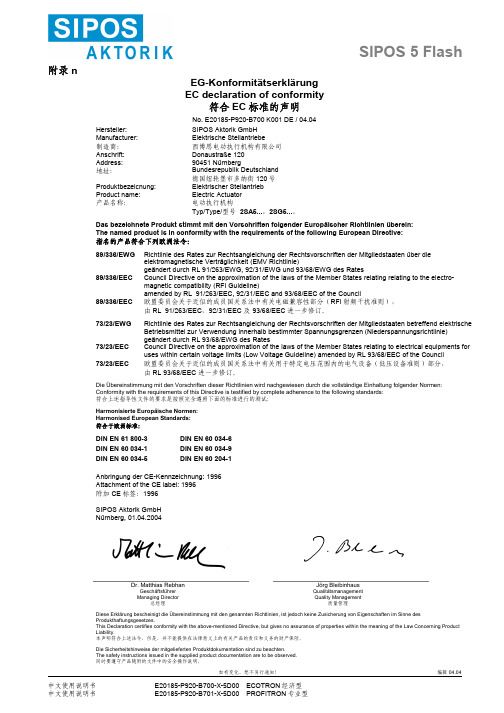
如有变化,恕不另行通知! 编辑 04.04中文使用说明书 E20185-P920-B700-X-5D00 ECOTRON 经济型中文使用说明书 E20185-P920-B701-X-5D00 PROFITRON 专业型附录 nEG-KonformitätserklärungEC declaration of conformity符合EC 标准的声明No. E20185-P920-B700 K001 DE / 04.04Hersteller: Manufacturer: 制造商: SIPOS Aktorik GmbH Elektrische Stellantriebe 西博思电动执行机构有限公司 Anschrift:Address:地址:Donaustraße 120 90451 Nürnberg Bundesrepublik Deutschland 德国纽轮堡市多纳街120号 Produktbezeicnung:Product name:产品名称: Elektrischer Stellantrieb Electric Actuator 电动执行机构Typ/Type/型号 2SA5...,2SG5...。
Das bezeichnete Produkt stimmt mit den Vorschriften folgender Europäischer Richtlinien überein:The named product is in conformity with the requirements of the following European Directive:指名的产品符合下列欧洲法令:89/336/EWGRichtlinie des Rates zur Rechtsangleichung der Rechtsvorschriften der Mitgliedstaaten über die elektromagnetische Verträglichkeit (EMV Richtlinie) geändert durch RL 91/263/EWG, 92/31/EWG und 93/68/EWG des Rates 89/336/EECCouncil Directive on the approximation of the laws of the Member States relating relating to the electro-magnetic compatibility (RFI Guideline) amended by RL 91/263/EEC, 92/31/EEC and 93/68/EEC of the Council 89/336/EEC欧盟委员会关于近似的成员国关系法中有关电磁兼容性部分(RFI 射频干扰准则), 由RL 91/263/EEC ,92/31/EEC 及 93/68/EEC 进一步修订。

ce自我声明模板1.引言1.1 概述概述通常是文章引言部分的一部分,用于介绍本文的主题和背景,以及文章的大致结构和目的。
对于CE自我声明模板的概述,可以参考以下内容:概述:CE自我声明模板是一种用于撰写个人自述或自我介绍的模板,旨在帮助个人全面展现自己的背景、成就和未来展望。
本文将介绍CE自我声明模板的主要结构和内容,以及如何利用这个模板进行有效的自我介绍。
对于准备写CE自我声明的人来说,了解这个模板的结构和要点非常重要。
本文将在接下来的章节详细介绍CE自我声明模板的各个部分,包括自我背景、个人成就、总结回顾和未来展望。
通过按照这个模板的要求进行撰写,可以确保个人的自述具备清晰的逻辑结构,同时全面地展示个人的优势和发展潜力。
除了介绍模板本身,本文还将提供一些编写CE自我声明的技巧和建议,以帮助读者更好地准备和完成自我介绍。
这些建议包括如何选择和组织材料、突出个人成就、展示个人的目标和未来计划等。
通过遵循这些指导,读者可以撰写出一篇生动、有力且富有说服力的CE自我声明。
最后,在介绍完模板的结构和编写技巧后,本文会回顾CE自我声明的重要性和应用场景。
CE自我声明作为一种自我介绍的方式,广泛应用于各种场合,包括求职、申请学校、参加竞赛或展示自己的能力等。
通过撰写一篇令人印象深刻的CE自我声明,个人可以在众多竞争者中脱颖而出,赢得更多的机会和认可。
综上所述,本文将详细介绍CE自我声明模板的内容和结构,提供关于编写这类自我介绍的技巧和建议,并说明CE自我声明的重要性和应用场景。
希望本文可以帮助读者更好地理解和应用CE自我声明模板,进而在个人介绍中取得更好的效果。
1.2文章结构1.2 文章结构本文将按照以下结构进行论述:引言部分将首先对本文的主题进行概述,明确文中所要讨论的内容以及目的。
在正文中,将分为两个主要部分进行论述。
第一个部分是自我背景,将介绍我个人的基本背景信息,包括教育背景、工作经历等。
第二个部分是个人成就,将详细介绍我在相关领域取得的成就,包括项目经验、专业技能等。

EC Declaration of conformityEG KonformitätserklärungCE Déclaration de conformitéWe/ Wir/Nous Mettler-Toledo AG, Process AnalyticsIm Hackacker 158902 UrdorfSwitzerlanddeclare under our sole responsibility that the product,erklären in alleiniger Verantwortung, dass dieses Produkt, déclarons sous notre seule responsabilité que le produit,Description/ Beschreibung/DescriptionInTrac7XX*1/*2/*3/*4/*5/*6*7*8NON-EX -Version, wetted parts : plastic material, > DN25NON-EX -Version, mediumberührte Teile : Kunststoffe, > DN25NON-EX -Version, parties en contact avec le milieu : matériaux plastics, > DN25 *1 – Operation mode (M =manual; P =pneumatic; R =pneumatic with pneumatic position indicators;X = pneumatic with Ex inductive position indicators or I = pneumatic with NonEx inductive position indicators ) *1 – Betriebsart (M =manuell; P =pneumatisch; R =pneumatisch mit pneumatischer Rückmeldung;X =pneumatisch mit induktiver Rückmeldung Ex or I =pneumatisch mit induktiver Rückmeldung NonEx ) *1 – Commande (M =manuelle; P =pneumatique; R =pneumatique avec indicateurs de positionpneumatiques ; X X = pneumatique avec indicateurs de position inductifs Ex or I = pneumatique avec indicateurs de position inductifs NonEx )*2 – Insertion length*2 – Eintauchlänge*2 – Profondeur d’immersion*3 – Wetted parts –– plastic plastic material material*3 – Mediumberührte Teile – Kunststoffe*3 – Parties en contact avec le milieu – matériaux matériaux plastics plastics*4 – Process connection >DN25*4 – Prozessanschluss >DN25*4 – Adaptation souple au procédé >DN25DN25 *5 – Wetted O-ring material*5 – Medium berührte O-Ringe*5 – Joints toriques mouillés*6 – Material of cylinder body (stainless steel or conductive Polypropylene)*6 – Material des Führungszylinders (rostfreier Stahl oder leitender Kunststoff)*6 – Matériaux du corps cylindrique (l’acier inox ou polypropylene conducteur*7 – Connection of rinsing chamber*7 – Anschlüsse an die Spülkammer*7 – Adaption de la chambre de rinçage*8 – Zero or specials*8 – Bezeichnung offen für Spezialversion*8 – Zéro ou réservé pour versions spécialesto which this declaration relates is in conformity with the following standard(s) or other normative document(s). auf welches sich diese Erklärung bezieht, mit der/den folgenden Norm(en) oder Richtlinie(n) übereinstimmt. auquel se réfère cette déclaration est conforme à la (aux) norme(s) ou au(x) document(s) normative(s)Pressure Equipment Directive Druckgeräte RichtlinieDiDirective Equipements sous pression 97/23/EC 97/23/EGEvaluation AssessmentBewertungsverfahrenProcédure d’EvaluationModul A/ Category I Modul A/ Kategorie Ifor fluids in group 1, exception instable gases für Fluidgruppe 1, mit Ausnahme instabiler Gase pour fluides groupe 1, exception gaz instablesPlace and Date of issue/Ausstellungsort/ - Datum Lieu et date d’émission Urdorf, November 9, 2006Mettler-Toledo AG, Process AnalyticsWaldemar RauchThomas Hösli General Manager PO Urdorf Head of Operations and R+DNorm/ Standard/ Standard EN 12266-1。

English 122009-04/2011 DURAG GmbHKollaustraße 105 · D-22453 Hamburg · Tel. +49 40 / 55 42 18-0 · Fax +49 40 / 58 41 54D-LE 603Flame SensorsD-LE 603Table of Contents1.Flame Monitoring Equipment / Burner Management Systems (1)2.UV Flame Sensors D-LE 603 UH and D-LE 603 US (1)2.1.General Information (1)2.2.Functional Description (2)2.3.Start-Up (2)2.4.Front Panel (3)2.5.Block diagram (3)2.6.Replacing UV Cells (4)3.UV Flame Sensors D-LE 603 UA and D-LE 603 UAF (6)3.1.General Information (6)3.2.Functional Description (6)3.3.Programmable Sensor Controls (7)3.4.Gain Setting (8)3.5.Test Plug for Input Gain Modulation (8)3.6.Setting the High-Pass Filter (9)3.7.Remote Change-Over (Gain Switch) (10)3.8.Block Diagram (11)4.IR Flame Sensors D-LE 603 IG and D-LE 603 IS (12)4.1.General Information (12)4.2.Functional Description (12)4.3.Programmable Sensor Controls (13)4.4.Logarithmic input amplifier (14)4.5.Setting a Brightness Threshold (15)4.6.Linear Input Amplifier (15)4.7.Gain Setting (16)4.8.Setting the Input Filter (16)4.9.Setting the High-Pass Filter (17)4.10.Block Diagram (18)5.IR Flame Sensors D-LE 603 ISE and D-LE 603 ISO (19)5.1.General Information (19)5.2.Functional Description (19)5.3.Programmable Sensor Controls (20)5.4.Gain Setting (21)5.5.Setting the High-Pass Filter (22)5.6.Block Diagram (23)6.Pulse Reduction Setting (24)7.Mounting the Flame Sensor (26)8.Mechanical Mounting System (26)9.Installation of the Flame Sensor (27)10.Safety Information (27)11.Maintenance / Service (28)12.Technical data of the D-LE 603 (28)13.Wiring Diagram (29)14.Overview of Available Models (30)15.Optional Accessories (31)16.Dimensional Drawing: D-LE 603 Flame Sensor Housing (32)17.D-LE 603.../94Ex and /95Ex Housing for Hazardous Areas .. (33)17.1.Adjusting the Flame Scanner D-LE 603.../94Ex and D-LE 603.../95Ex (34)18.D-LE 603 ... /96 Ex for Class I, Div. 2, Group A,B,C&D (35)D-LE 60319.D-LE 603 ... /97 Ex for Hazardous Areas Zone 2 . (36)20.Dimensional Drawing: D-ZS 033-I Swivel Mount (37)21. Dimensional Drawing: D-ZS 033-III Swivel Mount (38)22.Dimensional Drawing: D-ZS 133 Ball Valve (39)23.Certificates (40)23.1.ATEX Certificate (40)23.2.UL-Listing (41)23.3.CUL-Listing (41)23.4.FM-Listing (42)23.5.EC Declaration of Conformity (43)Diagrams(Fig. 1)Front panel of the D-LE 603 UH/US (3)(Fig. 2)Block diagram: D-LE 603 UH/US (3)(Fig. 3)Replacing the UV-cell in the D-LE 603 UH (4)(Fig. 4)Replacing the UV-cell in the D-LE 603 US (5)(Fig. 5)Front panel of the D-LE 603 UAF/UA (7)(Fig. 6)Gain settings on the D-LE 603 UA/UAF (8)(Fig. 7)Controls for the high-pass filter on the D-LE 603 UA/UAF (9)(Fig. 8)Example of a remote-controlled change-over in the D-LE 603 UA/UAF (10)(Fig. 9)Block diagram: D-LE 603 UA/UAF (11)(Fig. 10)Front panel of the D-LE 603 IG/IS (13)(Fig. 11)Controls for the logarithmic input amplifier on the D-LE 603 IG/IS (14)(Fig. 12)Logarithmic input curve of the D-LE 603 IG/IS (14)(Fig. 13)Controls for the linear amplifier on the D-LE 603 IS/IG (15)(Fig. 14)Controls for adjusting the high-pass filter on the D-LE 603 IG/IS (17)(Fig. 15)Block diagram: D-LE 603 IG/IS (18)(Fig. 16)Front panel of the D-LE 603 ISE/ISO (20)(Fig. 17)Gain settings on the D-LE 603 ISE/ISO (21)(Fig. 18)Controls for adjusting the high-pass filter on the D-LE 603 ISE/ISO (22)(Fig. 19)Block diagram: D-LE 603 ISE/ISO (23)(Fig. 20)Controls on the D-LE 603 UA/UAF for adjusting pulse reduction (24)(Fig. 21)Controls on the D-LE 603 IG/IS for adjusting pulse reduction (24)(Fig. 22)Controls on the D-LE 603 ISE/ISO for adjusting pulse reduction (25)(Fig. 23)D-LE 603 wiring diagram (29)(Fig. 24)Dimensional drawing: D-LE 603 flame sensor housing (32)(Fig. 25)Dimensional drawing: explosion-proof housing (33)(Fig. 26)Adjusting an explosion-proof flame sensor D-LE 603.../94Ex or D-LE 603.../95Ex .. (34)(Fig. 27)Dimensional drawing: D-LE 603.../96Ex .. (35)(Fig. 28)Dimensional drawing: D-LE 603.../97Ex .. (36)(Fig. 29)Dimensional drawing: D-ZS 033-I swivel mount (37)(Fig. 30)Dimensional drawing: D-ZS 033-III swivel mount (38)(Fig. 31)Dimensional drawing: D-ZS 133 ball valve (39)D-LE 603Tables(Table 1) Determining pulse reduction via the voltage signal from the test plug (25)(Table 2)Various flame sensor cables (copper cable) (27)(Table 3)Selection Criteria for the D-LE 603 (30)(Table 4)Overview of available models (30)D-LE 603 Page 11. Flame Monitoring Equipment / Burner Management Systems DURAG flame monitoring and burner management equipment are safety systems which consist of a controller and an optical flame sensor. These devices are suitable and approved for monitoring single and multi-burner applications of varying capacities, using a variety of fuels and combustion techniques. In order that the flame monitoring or burner management system may be adapted to local conditions, different ultraviolet (UV) and infrared (IR) flame sensors are available. If a parallel mounting of two flame sensors is necessary at the site (due to heavy spectral fluctuations in the flame or a need to monitor a pilot and primary flame), a combination of UV/IR, IR/IR or UV/UV flame sensors may be used.The D-UG 110/120/660 and D-GF 150/200 controllers, as well as the D-LE 103 and D-LE 603 flame sensors, feature self-checking circuitry and function according to the European Standards EN 230 (oil) and EN 298 (gas). They also comply with technical guidelines TRD 411-414 and 604 for intermittent, continuous and 72-hour operation.All flame sensors in the D-LE 103 and D-LE 603 series can operate with DURAG controllers and thanks to common interfaces.As stipulated in EN 298, the union nut on the D-LE 103/603 series flame sensors is equipped with a set screw to ensure that the sensor remains securely fastened in place.2. UV Flame Sensors D-LE 603 UH and D-LE 603 US2.1. General InformationThe UV flame sensor D-LE 603 US/UH has a gas-filled discharge tube with a pulse amplifier for detection in the ranges of 190-270 nm (D-LE 603 UH) and 190-280 nm (D-LE 603 US). Its spectral sensitivity lies in the UV-C range. Since energy in this spectral range can only be produced by flames, even in combustion chambers with extremely high temperatures, the glowing walls of a combustion chamber will not simulate a flame signal. The flame sensor has an optical viewing angle of 6° and therefore may be focused very effectively on the flame. When positioning the flame sensor, the bottom third of the flame (the flame’s root) must be considered, since it generates the greatest amount of UV energy.For self-checking purposes, an electromagnetic shutter in the D-LE 603 UH/US interrupts the path to the UV-cell. During this time, the flame sensor cannot generate a flame signal (pulse frequency).The D-LE 603 UH/US is specially suited for monitoring gas flames. Oil flames that are bright yellow or white in colour also can be detected and monitored by these sensors. However, if the colour of the oil flame is more orange or red, the use of a UV flame sensor is inadvisable. An IR flame sensor is better suited for such a task.It is vital that the sensor’s view of the flame be kept free at all times of oil mist, water vapour and dust particles. UV-C radiation may otherwise be partially or even totally absorbed.During oil operation, the ignition point of the flame may lift off slightly from the burner mouth. The resulting oil mist can restrict the view of the flame. This may be counteracted, however, by arranging the sighting tube longitudinally to the flame and turning the flame sensor more to the outside (i.e., from the core air to the secondary air).The use of a highly sensitive plate UV cell in the D-LE 603 US makes it possible to substantially increase responsiveness in this spectral range. Flames emitting low levels of energy, like mixed-gas flames or those of a blast furnace, may be reliably monitored.The D-LE 603 US should not be installed in a multi-burner system whose flames are high in UV intensity, since the sensor’s high sensitivity may cause it to display a strong ambient light signal from the flame of a neighbouring burner.Page 2 D-LE 6032.2. Functional DescriptionThe UV photocell in the D-LE 603 UH/US consists of a gas-filled discharge tube. The voltage level needed to trigger a discharge changes according to the level of radiation striking the tube. As UV intensity increases, the voltage level decreases, resulting in more frequent discharges from the UV-photocell. Every discharge generates a spike pulse which is standardised to a length of 125 µs using a monostable trigger circuit. These standardised pulses are then transmitted via the output amplifier to the controller or burner management system for evaluation.The electromagnetic shutter is a fail-safe measure which checks the UV photocell once the controller indicates a flame signal. As long as the flame recognition threshold of the controller is not exceeded, the shutter will remain open. Once flame is present, the UV photocell is blacked out every second for 0.2 seconds and checked for spontaneous ignition.2.3. Start-UpThe D-LE 603 UH/US does not feature any controls that require adjustment. To aid in aligning the sensor, a red signal diode and a jack for connecting the D-ZS 087-20 digital display are supplied (fig. 1). The cover on the housing must be opened in order to connect the digital display.If the digital display is connected and the burner is in operation, the sensor can be easily aligned. This is achieved by carefully moving the sensor, attached to the D-ZS 033 ball joint flange, to the position at which the highest pulse display (flame signal) is received. When performing the alignment, it is recommended that the flame recognition threshold on the controller be set to its lowest level (threshold level 9 for the D-UG 110/120 and D-GF 150/200; level 99 for the D-UG 660).The built-in red LED serves also to display the flame signal generated by the sensor. The brightness of the LED will increase as the pulse frequency increases. Once the controller has signalled flame ON, the LED will blink (the LED will go dark for 0.2 seconds every second). This indicates that the self-check function of the sensor is operating properly. If the LED remains illuminated continuously, either the flame recognition threshold has not been exceeded or the self-check has recognised a system error (e.g., defective shutter, shutter drive or UV cell).D-LE 603 Page 3 2.4. Front Panel L E 603-02-003 (Fig. 1)Front panel of the D-LE 603 UH/USTo optimally align the flame sensor with the combustion zone exhibiting the highest level of UV intensity, the D-ZS 087-20 digital display may be connected after removing the cover on the housing. The red “Signal” LED also serves to display the flame signal being generated.2.5. Block diagramShutter(Fig. 2)Block diagram: D-LE 603 UH/USPage 4 D-LE 603 2.6. Replacing UV CellsIf, after lengthy period of operation, a flame sensor no longer displays sufficient response sensitivity, or the flame monitor shuts down due to a sensor error, the cause may be an old UV cell. In this case, the UV cell can be replaced. The procedure below describes how to replace the UV cell (see figs. 3, 4). Instructions for Replacing the UV Cell (P603.1) in the D-LE 603:1. Loosen the four Allen screws (M5x10).2. Remove the sensor core from the housing and unscrew the three machine screws (M3x6)used to mount the D-LE 603 UH No. 1 printed circuit board.3. Carefully unplug the circuit board.4. Remove the P603.1 UV cell and insert the new cell. The red point on the UV cell (anode)must again be facing in the same direction.5. Loosen the M4x10 mm setscrew (2 mm Allen screw), such that the centring piece isloose. The UV cells have a certain degree of tolerance in terms of their overall height.6. Carefully plug the circuit board back into the sensor core and tighten it in place with thethree M3x6 mm machine screws.7. Place the centring piece back over the UV cell and fix it in place with the M4x10 mmsetscrew.8. Insert the sensor electronics back into the housing. Be careful not to pinch theconnection cable inside the housing, and be certain the front panel with the jack for the D-ZS 087-20 faces that side of the housing with the removable cover. Reassemble thehousing by tightening the four M5x10 Allen screws.(Fig. 3) Replacing the UV-cell in the D-LE 603 UHInstructions for Replacing the UV Cell (P622) in the D-LE 603 US:1. Loosen the four Allen screws (M5x10).2. Remove the sensor core from the housing, loosen the M4x10 setscrew (2 mm Allenscrew) and push up the centring piece.3. Pull out the P622 UV cell and insert the new UV cell. The red point on the UV cell (anode)must again be facing in the same direction (toward the optics).4. Carefully push the centring piece back onto the UV cell and tighten it in place with theM4x10 mm setscrew.5. Insert the sensor electronics back into the housing. Be careful not to pinch the connectioncable inside the housing, and be certain the front panel with the jack for the D-ZS 087-20faces that side of the housing with the removable cover. Reassemble the housing bytightening the four M5x10 Allen screws.4 mm AllenScrew (M5x10)(Fig. 4) Replacing the UV-cell in the D-LE 603 US3. UV Flame Sensors D-LE 603 UA and D-LE 603 UAF3.1. General InformationThe D-LE 603 UA/UAF are UV-sensitive flame sensors that can be used to monitor flames burning a variety of fuels. Their spectral sensitivities cover the UV-A and UV-B ranges (wavelengths of280-410 nm for the D-LE 603 UAF, and 190-520 nm for the D-LE 603 UA). These sensors only evaluate the flame signal generated by the modulation of the flame radiation, which occurs during combustion in the above spectral ranges. It does evaluate the constant UV-radiation. Due to the confined spectral sensitivity range for simultaneously analysing flicker frequencies, the D-LE 603 UA/UAF achieves a very high rate of single flame selectivity.If the sensor is installed in a multi-fuel application and the integrated remote change-over feature (gain switch) is required for input amplification, a D-UG 660 controller must be used, since it is equipped witha range-selection control.3.2. Functional DescriptionThe detectors installed in the flame sensor are UV-sensitive semiconductors, which generate a detector current in proportion to the constant and modulated flame radiation intensity. This current reaches the input amplification via a built-in electronic shutter, which interrupts the detector current once every second as a self-checking feature.The preamplified signal arrives at one of two independently programmable ranges (A or B) thanks to the remote change-over function. Each range features four amplification settings (hook switches 1-4) and three high-pass filter settings ≥30 Hz, ≥70 Hz and ≥120 Hz (hook switches 70 Hz and 120 Hz). If the range selection function on the D-UG 660 controller is used to activate the remote change-over, a switch will occur from range A to range B.The programmable AC voltage amplifier of the activated range processes only the alternating signals occurring due to the modulation of the flame. Those frequency portions lying below the setting of the high-pass filter are then strongly suppressed. Rectification with a subsequent voltage-frequency conversion generates a pulse frequency (flame signal) that is transmitted to the controller for evaluation.3.3. Programmable Sensor ControlsTo adapt to characteristics found in a diversity of burners, burner arrangements and fuels, theD-LE 603 UA/UAF flame sensor features programmable controls. The flame sensors are delivered from the factory with the following settings (unless a special request was made in advance): •Amplification setting:.................... R ange A Gain 2 Range B Gain 3•Filter setting: ................................ Both 70 Hz•Pulse reduction potentiometer: .... N o pulse reduction (voltage at the test plug approx. 5.5 VDC) For site-specific modifications of the above settings, the housing cover on the flame sensor must be opened.!T he flame sensor must be voltage-free prior to switching the hook switches.Yellow LED indicatesselected rangeOutlet M1 for measur-ing amplification levelinput amplifier (Fig. 5) Front panel of the D-LE 603 UAF/UA3.4. Gain SettingEach range (A and B) uses four amplification settings (see fig. 6). The desired setting is achieved by hooking one of the hook switches 1-4. Gain setting 1 activates the smallest amplification, while setting 4 activates the largest. Only one hook switch for the gain setting may be activated for each range. Depending on the amount of ambient light and the intensity of the flame signal, the gain should be set such that the ambient light signal is a low as possible while the flame signal is still sufficiently high. It is of no use if the gain is reduced to a point at which the ambient light goes back to zero, but the flame signal cannot reliably exceed the flame recognition threshold of the controller throughout the entire load range of the burner. Please see the section entitled “Setting the Flame Recognition Threshold” in the operations manual of the appropriate controller.If there is no ambient light displayed at even the highest gain setting, it is not necessarily best, for reasons of availability, to choose this particular setting. The amplification should be reduced to the lowest possible level at which any impermissible lift-off of the flame from the burner is still recognised and reported. This must also be done in connection with the flame recognition threshold of the controller.Using the remote change-over feature on the flame sensor, the operator can switch to the preset amplification of range B at a any desired point in time (e.g., change in fuel type, combustion chamber temperature rises to particular temperature, recirculated flue gas introduced into fuel mix). The yellow LED will illuminate when the remote change-over is activated.If the remote change-over is used, range A must, for safety reasons, always be set to a lower gain setting than range B.(Fig. 6) Gain settings on the D-LE 603 UA/UAF3.5. Test Plug for Input Gain ModulationTo avoid over-amplification of the input stage, the “input gain modulation” test plug M1 (see fig. 6) is available for test measurements. When the flame sensor optics are covered, a 9V ± 1 V DC voltage signal must be measured at the test plug. If the flame sensor is exposed to UV-radiation, the voltage signal will decrease, inversely proportional to the incidental radiation. If this voltage signal drops to ≤2V, the input stage is over-modulated. If the D-LE 603 UA has been installed, the operator may instead wish to use a D-LE 603 UAF. Otherwise, a reduction in the amplification can be carried out at the factory.3.6. Setting the High-Pass FilterA further aid in flame selection is the frequency suppression setting. Experience has shown that flicker frequencies are highest in the flame's root (≥ 70 Hz) and decrease towards the flame tip (≤ 70 Hz). Flame flicker frequencies in the lower frequency range of the detector current generated by the flame can be suppressed using the hook switches for the filtering stage (high-pass filter). If none of the hook switch pairs have been activated, only those flicker frequency portions <30 Hz are suppressed. If a higher level of ambient light makes it necessary to suppress flicker frequencies up to 70 Hz (or 120 Hz), the corresponding pair of hook switches must be hooked (70 or 120 Hz, see fig. 7).(Fig. 7) Controls for the high-pass filter on the D-LE 603 UA/UAFFor selective flame monitoring, it is very important that the correct viewing position is chosen and that the flame sensor is properly aligned with the flame it is to monitor. These are to be determined such that the flame sensor is aligned with the root of the flame, where higher flicker frequencies are found and a high, stable flame signal (pulse frequency) is generated, even if the high-pass filter is set to 70 or 120 Hz. If the burner has been shut off but light from the flames of neighbouring burners (ambient light) is picked up by the sensor, a high-pass filter setting of 70 or 120 Hz is in general enough to greatly suppress it, since such ambient light is typically low in frequency (≤70 Hz).Different filter settings may be chosen for the two ranges, which as mentioned can be activated at a desired point in time via the remote change-over function. If both ranges have the same gain setting, and only distinguish themselves with respect to the high-pass filter setting, the higher frequency must, for safety reasons, be set in range A.!To maintain the fail-safe nature of the sensor, all hook switches must be switched in pairs. More than one pair of hook switches may never be engaged simultaneously.!The higher the filter frequency setting, the lower the pulse rate output from the flame sensor, since fewer portions of the flame are being evaluated.3.7. Remote Change-Over (Gain Switch)In burners using multiple fuels (e.g., combined oil/gas burners), the intensity of the flame may vary greatly. The flame sensors may be specifically switched to the input gain necessary for optimal monitoring of the different fuels or combustion methods.The remote change-over feature enables a switch to be made between the preset gain and filter settings in the flame sensor. Applying a voltage of +24 VDC ±20 % to the trip line of the “Remote Change-Over” will initiate a switch from range A to range B. This switching voltage can be taken from an external potentially separated DC source or the internal operating voltage of the D-UG 660 controller (U B = +20 VDC).!If the flame sensor is operated with the remote change-over feature, either the gain for range A must be less than range B, or the filter setting must be set higher than that of range B. This is necessary in case of error (interruption of the trip line) so that the least sensitive range is always active. A short-circuit in the trip line will be recognised via the fail-safe range selection of theD-UG 660.For safety reasons, the trip line for the remote change-over must be connected to a range selection input in the D-UG 660 controller. If, for example, a short circuit in the trip line leads to an unwanted remote change-over, a second range would be simultaneously selected in the controller. The simultaneous selection of several ranges is not permissible, and will trigger an shutdown (display will indicate “Range Error”). The driver of the remote change-over must correspond to DIN VDE 0116. Flame sensor input amplification, necessary perhaps due to different types of combustion, may be changed by switching the range selection in the D-UG 660 controller.(Fig. 8)Example of a remote-controlled change-over in the D-LE 603 UA/UAFThe circuit diagram in figure 8 details a remote change-over via the potential-free contacts of a burner control system. Range 1 should be selected for oil, range 2 for gas and range 3 for mixed fuel combustion. If range 2, “Gas-Fired”, were selected on the controller, the flame sensor would then automatically switch from amplification 2 / 70 Hz (range A) to the higher amplification of range B (amplification 3, filter setting 30 Hz).3.8. Block Diagram(Fig. 9) Block diagram: D-LE 603 UA/UAF4. IR Flame Sensors D-LE 603 IG and D-LE 603 IS4.1. General InformationUV flame sensors cannot be employed for flame monitoring in modern burners using special techniques to guarantee combustion with low harmful emissions. Due to delayed combustion, there may not be any UV radiation present during combustion. The zone containing UV energy may also lie outside the viewable range of the flame sensor. This also applies in most cases to coal-fired burners. IR flame sensors are therefore available for these application ranges.The IR flame sensors D-LE 603 IS and D-LE 603 IG are suitable for monitoring flames burning a variety of fuels, in a variety of burner configurations. The controls on these flame sensors may be adjusted for operation in every combustion setting. Even problematic flame signal/ambient light relationships can overcome and monitored. With the aid of built-in test plugs, the determined settings may be read or reset at any time.The spectral sensitivity of the D-LE 603 IS covers a range of 300 - 1100 nm. The D-LE 603 IG covers a range of 780 - 1800 nm. Because of its wide spectral range, the D-LE 603 IG, is able to monitor gas flames in addition to coal and oil flames.The flame sensor has a linear and a logarithmic input amplifier, which may be selected for activation using hook switches.The logarithmic input amplifier can achieve a very high level of amplification and is therefore able to monitor flames in difficult viewing positions or radiating low levels of energy. As intensity increases, the amplification is reduced according to a logarithmic response curve. If flame intensity is high, however, saturation may occur.The linear input amplifier does not attain the high amplification of the logarithmic amplifier. It instead operates at a constant amplification level over its entire range, and is not subject to saturation at high levels of intensity.4.2. Functional DescriptionThe IR-detector installed in the flame sensor generates a current proportional to the impinging radia-tion intensity of the flame. To make the sensor fail-safe, a self-check is performed by periodically interrupting this detector current with an electronic shutter. According to choice, and depending on the settings of the hook switches, the detector current is fed to the linear or logarithmic input amplifier for signal amplification. The adjustable high-pass filter only accepts the typical flame flicker frequencies of >15, >60 or >120 Hz. Through rectification and voltage-frequency conversion, this voltage signal is converted into a pulse rate, whose pulse train increases with the flame's intensity. This pulse rate is transmitted to the controller for evaluation via an output amplifier.4.3. Programmable Sensor ControlsTo adapt to characteristics found in a diversity of burners, burner arrangements and fuels, theD-LE 603 IS/IG flame sensor features programmable controls. The flame sensors are delivered from the factory with the following settings (unless a special request was made in advance): • Hook switch “LIN on”: ....................... ON • Hook switch “LOG on”: ..................... OFF • Gain setting: ..................................... 4 • Input filter: ......................................... F1 • Filter setting: ..................................... 15 Hz• Potentiometer …Pulse Reduction“: .... no pulse reduction (voltage at test plug ±. 5.5 VDC) •Brightness threshold: ........................ set to minimum (voltage at test plug M3 ± 8.5 VDC)For site-specific modifications of the above settings, the housing cover of the flame sensor must be opened.!T he flame sensor must be voltage-free prior to switching the hook switches.L E 603-11-003Gain of line channel (amplification set to 4)Input filter(Filter F1 switched on)On switch of line channel input amplifier (”On” setting)On switch of logarithmic channel input amplifier (”Off” setting)Adjustment of high-pass filter /setting f => 15 Hz)Red LED for optical indication of output pulses(Fig. 10)Front panel of the D-LE 603 IG/IS。
EC Declaration of ConformityBT/CE-04-2014 (A/0)Page 1/1 EC Declaration of ConformityManufacturer :whose single Authorized Representative:XXXXXXXXXXXX CO.,LTDXXXXXXXXXXXXXXXXXXXXXWe, the manufacturer, herewith declare that the products DISPOSABLE STERILE RETRACTABLE SAFETY SYRINGE UMDNS -Code: 12132; GMDN-Code/Preferred Terms: XXXXXmeet the provisions of Directive 93/42/EEC which apply to them.The medical device has been assigned to class IIa according to Annex IX of the Directive 93/42/EEC. It bears the mark0197The product concerned has been and manufactured under a quality management system according to Annex V of Directive 93/42/EEC.Compliance of the designated product with the Directive 93/42/EEC has been assessed and certified by the Notified BodyTÜV Rheinland LGA Products GmbHTillystraße 2, 90431, Nürnberg, GermanyCertificate No.: xxxxxxxxxIssue date: xxxxxxxxxExpiry date: xxxxxxxxxfollowing the procedure relating to the EC Declaration of Conformity set out in Annex V of Directive 93/42/EEC.This Declaration of Conformity covers all medical devices as specified in the product list belonging to this declaration and is only valid in connection with a batch specific Certificate of Compliance for all products concerned bearing the CE markThe above mentioned declaration of conformity is exclusively under the responsibility ofCompany: XXXXXXXXXXXXXXXXAddress: XXXXXXXXXXXXXXXXXXXXXXXXXXXXXXXXXPlace, date Legally binding signature, Function。
declaration of conformity模板Declaration of Conformity[Your Company Name][Your Company Address][City, State, ZIP Code][Date]Subject: Declaration of Conformity for [Product Name/Model Number]To whom it may concern,We, [Your Company Name], hereby declare that the [ProductName/Model Number], manufactured and supplied by us, complies with all relevant regulations and standards according to the following:1. Product Information:- Product Name: [Product Name/Model Number]- Manufacturer: [Your Company Name]- Manufacturing Date: [Date]- Batch/Serial Number: [Batch/Serial Number]2. Applicable Standards:- [List of applicable standards and regulations that the product complies with]3. Technical Specifications:- [Detailed technical specifications and features of the product]4. Testing and Certification:- The product has been tested in accordance with [relevant testing methods] to ensure compliance with the applicable standards.- [Certification Body] has issued the necessary certifications and test reports, which are available upon request.5. Compliance with Regulations:- The [Product Name/Model Number] complies with all relevant regulations and directives, including but not limited to:a) [List applicable regulations and directives, e.g., European Union CE marking]b) [Specify any specific requirements or certifications, if applicable]6. Safety and Environmental Considerations:- The [Product Name/Model Number] has been designed, manufactured, and tested to meet all safety requirements and minimize any potential environmental impact.- [Provide details of any safety features or eco-friendly initiatives implemented in the product]7. Responsible Party:- [Your Company Name] assumes full responsibility for the design, manufacturing, and conformity of the [Product Name/Model Number].- Point of Contact: [Name], [Job Title]- Email: [Email Address]- Phone: [Contact Number]This Declaration of Conformity is issued under our sole responsibility and in accordance with the relevant regulations and standards. It is valid for the specified product and remains in effect until any significant changes occur, or the product is discontinued from production.We hereby declare that all the information provided in this declaration is true, accurate, and complete to the best of our knowledge.Sincerely,[Your Name][Your Title/Position][Your Company Name]。
declaration of conformity模板Declaration of Conformity[Your Company Name][Address][City, State, ZIP][Phone Number][Email Address][Website]Declaration of ConformityProduct Information:Product Name: [Product Name]Model Number: [Model Number]Serial Number: [Serial Number]Manufacturer: [Manufacturer]Date of Manufacture: [Date of Manufacture]I, [Your Name], as a representative of [Your Company Name], hereby declare that the above-mentioned product complies with all applicable standards and regulations as set forth by the relevant authorities. This declaration is based on the conformity assessment procedure carried out byour company in accordance with the requirements specified in [applicable standards/reference documents].1. Description of the Product:[List a detailed description of the product.]2. Applicable Standards and Regulations:[List all applicable standards and regulations that the product conforms to.]3. Technical Documentation:[Describe the technical documentation that supports the product's conformity, including test reports, design specifications, and other relevant documents.]4. Manufacturing Process:[Describe the manufacturing process, including quality control measures implemented to ensure the product's compliance with applicable standards and regulations.]5. Testing and Certification:[List any third-party testing or certification received by the product, if applicable.]6. Storage and Transportation:[Explain any specific storage or transportation requirements necessary to maintain the product's conformity.]7. Warranty and Support:[Describe the warranty terms and after-sales support provided for the product.]8. Contact Information:[Provide contact information for inquiries or further information regarding the product's conformity.]I declare that the above information is true and accurate to the best of my knowledge. Any changes or modifications made to the product without the written consent of the manufacturer may void this declaration of conformity.[Your Name][Title/Position][Date]Please note that this is a template for a Declaration of Conformity and should be tailored to fit the specific requirements of your product and industry. It is important to consult with legal experts and regulatory bodies to ensure compliance with all relevant regulations and standards.。
declaration of conformity模板[Your Company Logo]Declaration of Conformity[Company Name][Company Address][City, State, ZIP Code][Country][Date]To whom it may concern,This is to declare that the following products manufactured and/or imported by [Company Name] comply with the relevant standards and regulations as indicated below:1. Product Information:Product Name:Model/Part Number:Description:Serial Number (if applicable):2. Standards and Regulations:[List the standards and regulations that the product conforms to, such as safety, electromagnetic compatibility, environmental, etc.]3. Technical Specifications:[Provide specific technical details and specifications of the product if required by regulations.]4. Testing and Certification:[Outline the testing procedures and certifications obtained for the product, including the name and address of the testing laboratory if applicable.]5. Manufacturer's Information:[Provide information about the manufacturer, including name, address, and contact details.]6. Authorized Representative:[Specify the details of the authorized representative, if applicable.]7. Compliance Statement:We hereby declare that the above-mentioned product complies with all applicable standards and regulations.8. Additional Information (if applicable):[Include any additional information or declarations required by specific regulations or customer requirements.]This Declaration of Conformity is issued to demonstrate our commitment to producing and delivering products that meet or exceed the necessary standards and regulations. We take full responsibility for the conformity of the products mentioned above.Should you require any further information or documentation regarding the conformity of our products, please do not hesitate to contact us.Thank you for your attention to this matter.Sincerely,[Your Name][Your Position][Company Name][Company Contact Information]。