三星ML1610维修手册全00
- 格式:pdf
- 大小:78.49 KB
- 文档页数:3
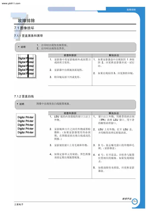


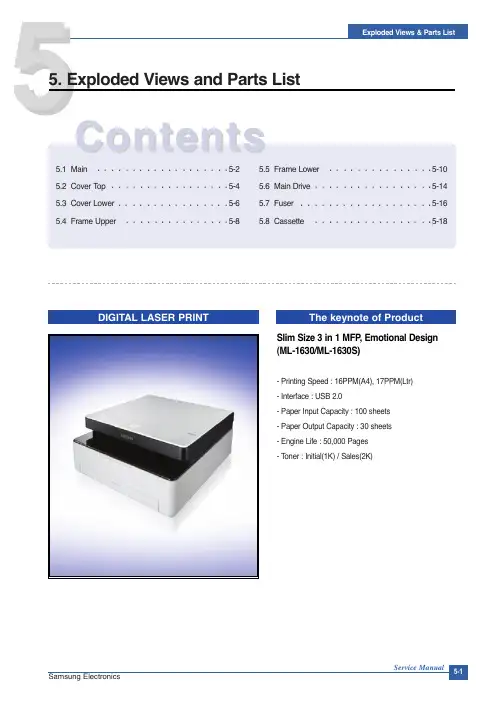
SAMSUNG LCD Projection TV SERVICE GUIDE*Supercedes and appends service manual data*Covers Models: (L52A & L56A-Chassis)PLH403W, PLH403W1, PLH403WS, PLH403W3, PLH403WS3PLK435WS, PLK405WSLJ402W, SLK407WSAMSUNG LCD Projection TV SERVICE GUIDETable of ContentsSections1. How to Use This Guide2. Service Bulletins3. Flow Charts4. Parts Data5. Assembly/Disassembly6. Escalation/Who to CallHow to use this GuideThis guide is divided into seven sections. Start with the section marked“Instructions”.The models covered in this document are derived from the L52A chassis. However; this chassis has several different versions that are NOT covered in the service manuals.Instructions to Start Service:1. Obtain model, serial and symptom.2. Review service bulletins (section 2), for common fixes. If Service Bulletin states thatrepair is common, complete repair as indicated. Otherwise, proceed to section 3.3. If the previous steps do lead to a clear diagnosis, then proceed to the flow chart insection 3 to help assist you in determining the correct PCB’s to order.4. Place order through Samsung Parts Department.Note: Distributors DO NOT carry PCB’s, so backorder with no eta will result. PartsDepartment will not accept an order for PTV parts without a serial number becausecorrect ID cannot be assured.5. Parts will automatically ship 2nd day.6. When installing parts (refer to section 6 - Assembly/Disassembly), repair alignmentor adjustment will be necessary.Geometric; Color Temp, etc. – to enter, press “Mute 182”Important Points:1. Auto Mileage: We will pay $0.50 per mile travel time without special approval, up to50 additional miles beyond the 25 miles required by contract. However; you mustprovide proof, such as Internet driving directions or similar verifiable map and attach it to the claim when submitted.Subject: Microprocessor (IC901) software upgrade.Background:1. During channel up / down, a pop noise is heard when connected to the “Monitor Audio / Video Output Jacks”.2. When using the DVD component input jacks, “COMPONENT” flashes (OSD).Countermeasure: Replace IC901.Parts list: Parts #: AA13-30005F.SERVICE BULLETINPRODUCT: PJTBULLETIN: LCD-01 MODEL: PLH403WSubject: White balance and gamma adjustment.Background: When the white balance and gamma adjustment can not be performed by visual method, refer to method using test equipment.Countermeasure: Adjustment using test equipment: Equipment:1. NTSC signal generator, 10 – step signal. Each step of 10 IRE, last step is 100 IRE. This can be confirmed by using waveform monitor.2. Color & chromaticity meter (Minolta CS-100).Procedure: Set the color temperature to the value listed below, using the color &chromaticity meter with a specific step displayed by the signal generator. Adjust values in the service mode to achieve good white balance and gamma. Refer to servicemanual page 5-4 & 5-5. To enter service mode, press Mute - 1 – 8 – 2 with power off. Power set on; service mode will be displayed.1. High light 80 IRE: Y=(13+/- 3.0), x=(0.285+/- .007), y=(0.284+/- .007). Use control No. 20(Sub contrast, 22(R sub contrast), 23(B sub contrast).2. Mid light 40 IRE: Y=(2.4+/- 0.5), x=(0.284+/- .007), y=(0.272+/- .007). Use control No. 15(Sub bright), 16(B sub bright), 17(R sub bright).3. Low light 20 IRE: Y=(0.3+/- 0.1), x=(0.291+/- .007), y=(0.264+/- .007). Use control No. 7(Gamma ctrl 1), 8(R gamma ctrl 1), 9(B gamma ctrl 1).Note: Repeat adjustment of each control to achieve best results.SERVICE BULLETINPRODUCT: PJTBULLETIN: LCD-02MODEL: All LCD modelsDis-assembly ProcedureDis-assembly Procedure1. Open bottom cabinet2.Unscrew bracket-back3.Unscrew Bottom screw4.Unscrew Bottom screw below 2screw5.open Flat cable and 2 screw6.open connector7.unscrew 1 screw 8.exchange Optical EngineSection 6 - Escalation/Who to CallEscalation Paths and Technical Support1. Parts IssuesIf wrong or defective parts are received, contact Parts Department with theinvoice or PO numbers to resolve.If the parts do not fix the problem and you need technical assistance:973-601-6124 between 9:00 – 5:30 EST3. Regional Service Engineers are available for each geographic region. They are yourprimary contact for all technical and policy related issues that cannot be resolved through normal means. Their regions and phone numbers:West Zone: Jeff Reeves 310-537-7000 x131Mid-West Zone: Mark Rowland 630-879-1401East Zone: Anthony Ippolito 973-601-6005South Zone: Dan Girdley 678-560-91404. Website: Logon: ID = your account numberPassword = your zip codeOur ASC website contains most service manuals in PDF format ready for download.To use these files you need Adobe Acrobat Viewer which can be downloaded forfree @ . This site also contains other support data; i.e. servicebulletins, BIOS files and our policy guide.。
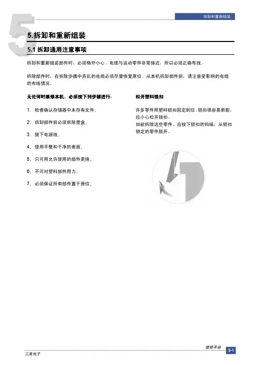
5.拆卸和重新组装5.1拆卸通用注意事项拆卸和重新组装部件时必须格外小心电缆与运动零件非常接近所以必须正确布线拆除部件时在拆除步骤中弄乱的电缆必须尽量恢复原位从本机拆卸部件前请注意受影响的电缆的布线情况无论何时维修本机必须按下列步骤进行1检查确认存储器中未存有文件 2拆卸部件前必须拆除墨盒 3拔下电源线4使用平整和干净的表面 5只可用允许使用的部件更换 6不可对塑料部件用力 7 必须保证所有部件置于原位 松开塑料锁扣许多零件用塑料锁扣固定到位锁扣很容易断裂应小心松开锁扣如欲拆除这些零件应按下锁扣的钩端从锁扣锁定的零件脱开5.2多用托盘1.打开前盖2.松开墨盒3.抓住多用托盘并朝箭头方向推多用托盘5.3拾取辊1.在拆除拾取辊之前应该拆除-多用托盘参照5.22.如欲更换拾取海绵一边按下拾取外壳B 两侧的钩了一边拉开拾取外壳U5.4前盖1.打开前盖2.如欲拆除前盖首先朝箭头方向左侧用轻微的压力拉前盖右侧下面的部分5.5纸盒托盘1.打开纸盒托盘2.如下图所示如欲拆除纸盒托盘一边按住本机左侧一边用轻微的压力朝箭头方向提起旋钮5.6后盖1.拆除紧固后盖的四个螺钉并拆除后盖2.打开卡紧盖3.如下图所示如欲拆除后盖必须保证右电源开关不会卡住4.必要时如下图所示朝箭头方向拆除卡紧盖5.7右盖1.在拆除右盖之前应该拆除 -前盖参照5.4 -后盖参照5.62.拆除紧固右盖的一个螺钉3.如下图所示对右盖背部轻轻用力并朝箭头方向向右侧推右盖5.8左盖1.在拆除左盖之前应该拆除 -前盖参照5.4 -后盖参照5.62.拆除紧固左盖的一个螺钉3.如下图所示对左盖背部轻轻用力并朝箭头方向向左侧推左盖4.从主印刷电路板组件拔下扬声器连接器5.必要时拆除紧固扬声器的两个螺钉并拆除扬声器5.9扫描组件1.在拆除扫描组件之前应该拆除-后盖参照5.6-右盖参照5.7-左盖参照5.82.从中盖拆除两个螺钉并拆除紧固接地电缆的螺钉3.如下图所示拔下三个连接器ADF扫描电动机OPE4.如下图所示朝箭头方向松开扫描组件5.10 ADF 外壳1.在拆除ADF外壳之前应该拆除 -扫描组件参照5.92.如下图所示打开ADF 外壳并将一字形螺丝刀插入槽中并从压盘外壳和ADF外壳拆除合页盖3.从压盘外壳拆除ADF 外壳此时如下图所示小心从压盘外壳松开ADF电动机线束4.拆除紧固ADF 组件的两个螺钉并拆除ADF组件此时如下图所示小心从压盘盖松开ADF 电动机线束5.必要时如下图所示拆除紧固TX 码纸板组件的两个螺钉并拆除码纸板组件6.如下图所示打开敞开盖并朝箭头方向拆除敞开盖7.如下图所示拉衬套然后旋转衬套直到转到槽为止然后提起拾取组件8.如下图所示拆除紧固上ADF 的两个螺钉并将一字形螺丝刀插入槽中并拆除上ADF9.如下图所示从ADF 印刷电路板组件拔下连接器拆除紧固ADF 电动机外壳的四个螺钉并朝箭头方向拆除ADF电动机外壳5.11 OPE 组件*当拆卸和组装SCX-4321时请参照本步骤1.如下图所示打开ADF 外壳并将一字形螺丝刀插入开缝中并从压盘外壳拆除OPE 组件2.如下图所示拔下三个连接器电池OPE 全部传感器3.拆除紧固OPE 印刷电路板组件的五个螺钉并拆除OPE 印刷电路板组件4.如下图所示松开接触橡胶5.如下图所示松开按键5.12压盘外壳1.在拆除压盘外壳之前应该拆除 -扫描组件参照5.9 -ADF外壳参照5.10 -OPE 组件参照5.112.如下图所示从上扫描组件拆除五个螺钉并从下扫描组件拆除上扫描组件3.取出电池4.如下图所示朝箭头方向推支座并拆除皮带同时取出CIS5.从CIS松开皮带和扁平电缆6.拆除紧固扫描电动机组件的两个螺钉并拆除扫描电动机组件7.必要时拆除紧固扫描电动机的两个螺钉并拆除扫描电动机8.如下图所示使用一字形螺丝刀拆除整个传感器5.13中盖1.拆除中盖之前应该拆除 -扫描组件参照5.92.如下图所示拆除紧固中盖的五个螺钉3.如下图所示小心从主印刷电路板组件松开中盖4.必要时取出码纸板5.14 HVPS1.拆除HVPS 之前应该拆除 -扫描组件参照5.9 -中盖参照5.132.拆除紧固护板的三个螺钉并拆除护板3.如下图所示拆除紧固HVPS 的三个螺钉并随HVPS 接地板一起拆除HVPS4.从HVPS拔下连接器5.15主印刷主印刷电路板组件电路板组件1.在拆除主印刷电路板组件之前,应该拆除 -扫描组件参照5.9 -中盖参照5.132.如下图所示从主印刷电路板组件拔下所有连接器3.拆除紧固主印刷电路板组件的六个螺钉并拆除主印刷电路板组件5.16 RX 驱动装置1.在拆除RX驱动装置之前应该拆除 -扫描组件参照5.9 -中盖参照5.13-主印刷电路板组件参照5.152.必要时如下图所示拆除两个支架端口主印刷电路板组件和接地板3.如下图所示拆除紧固引擎板的两个螺钉并拆除紧固机架的六个螺钉然后朝箭头方向拆除RX 驱动装置4.如下图所示拆除连接器5.如下图所示从机架松开四个齿轮RDCN OPC 定影单元进纸6.拆除紧固电动机支架的四个螺钉并拆除电动机支架然后拆除紧固电动机的两个螺钉并拆除电动机5.17定影单元1.拆除定影单元之前应该拆除 -扫描组件参照5.9 -中盖参照5.132.如下图所示从SMPS 和主印刷电路板组件拔下两个连接器3.如下图所示拆除紧固定影单元的四个螺钉并拆除定影单元4.如下图所示朝箭头方向拆除出纸动作中杆5.如下图所示拆除安全中盖6.如下图所示拆除出纸导向中盖7.如下图所示朝附到F/下出纸辊和出纸齿轮DRV17上的箭头的方向旋转支座主辊FR 辊F/下支座弹簧同时弹出注意如果未遵循上述说明弹簧将弹出推动机架组件内的主辊FR 辊F/下支座8.拆除紧固加热盖的两个螺钉并拆除加热盖9.如下图所示取出恒温器然后松开CFB 线束10.拆除紧固线束的螺钉并拆除线束然后如下图所示取出热敏电阻11.如下图所示从卤素灯松开CBF 线束并拆除紧固卤素灯的两个螺钉12.拆除紧固中盖的两个螺钉并拆除中盖13.如下图所示朝箭头方向取出卤素灯维修手册三星电子5.18引擎板LIU PBASMPS1.在拆除引擎板之前应该拆除 -扫描组件参照5.9 -中盖参照5.132.从SMPS 和LIU 印刷电路板组件拔下所有连接器3.如下图所示拆除紧固引擎板的六个螺钉并松开线束然后小心从进纸传感器致动器杆松开引擎板4.当只拆除SMPS 时首先拆除后盖参照5.6拔下定影单元连接器并拆除紧固SMPS 的六个螺钉然后如下图所示从主印刷电路板组件拔下连接器并小心松开SMPS5.当只拆除LIU 印刷电路板组件时首先拆除后盖参照5.6并拆除紧固LIU 印刷电路板组件的两个螺钉然后如下图所示从主印刷电路板组件拔下连接器并松开LIU印刷电路板组件维修手册 三星电子5.19激光扫描器1 拆除激光扫描器之前应该拆除-扫描组件参照5.9 -中盖参照5.132 除紧固激光扫描器的三个螺钉并拆除激光扫描器然后从激光扫描器拔下两个连接器维修手册三星电子5.20纸张路径机架1 拆除纸张路径机架之前应该拆除-扫描组件参照5.9 -中盖参照5.13-定影单元参照5.17 -引擎板参照5.182.下图所示拆除紧固纸张路径机架的四个螺钉并朝箭头方向拆除该机架3.如下图所示从机架拆除转印辊4.如下图所示拆除紧固多用电磁线圈的螺钉并拆除该电磁线圈。
GW-C1/C1d机器代码: B282/B283维修手册先阅读此前言安全注意事项重要安全注意事项身体伤害的预防1. 拆卸或装配复印机和外围设备的部件之前,请确认复印机的电源插头是拔下的。
2. 墙上插座应靠近复印机,并且容易接近。
3. 注意即使电源开关是关闭的,复印机的有些部件和纸盘单元仍供有电源。
4. 复印机完成预热前或在初始化中,若启动了作业,请将手远离机械及电气部件。
因为机器一旦完成预热,就会开始运行。
5. 复印机在运行时,定影装置的内部及金属部件变得极其烫手。
小心避免用手触摸它们。
健康安全条件色粉和显影剂是无毒的,但如果意外地把它们弄入眼中,可能暂时地造成眼睛不适。
请用滴眼液或用水冲洗作为急救。
若不能解决问题,请接收治疗。
遵守电气安全标准复印机及其外围设备的安装及保养必须由受过这些机型全面培训的客户服务代理商执行。
处置时安全及生态学上的注意事项6. 不要焚烧色粉筒或废粉,色粉遇到明火时会迅速点燃。
7. 根据当地规则处理废粉、显影剂及有机光导体(这些均是无毒物品)。
8. 根据当地规则处置更换的部件。
iii激光安全事项器件和放射性健康中心 (CRDH) 禁止在现场修理激光光学装置。
光学腔体装置只能在工厂或有必备设备的地点加以修理。
激光子系统可由有资格的客户工程师更换。
客户工程师因此在更换后可直接把所有的匣子和激光子系统返回到工厂或维修点。
本手册指定之外的控制、调整或操作程序的应用可导致危险的放射性照射。
激光单元的警告警告: 在尝试激光光学装置一节的程序之前,请关闭主开关。
否则,激光光束会严重地伤害你的眼睛。
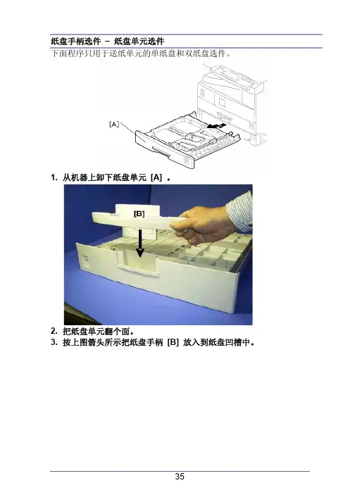
警告标记:符号和缩写本手册使用了几种符号及缩写,它们的含义为如下:参见或参考开口环螺丝接头SEF 短边进送(纵送)LEF 长边进送(横送)警告注意重点iii目录先阅读此前言 (i)安全注意事项 (i)身体伤害的预防 (i)符号和缩写 (iii)安装 (1)安装 (1)环境 (1)机器水平位 (2)最小占有空间 (2)电源要求 (3)复印机的安装 (4)外围设备的电源插座 (4)附件检查 (4)安装程序 (5)压板安装 (9)附件检查 (9)安装程序 (9)ARDF 安装 (10)附件检查 (10)安装程序 (11)ADF 安装 (14)附件检查 (14)安装程序 (15)双纸盘单元的安装 (18)附件检查 (18)安装程序 (19)单纸盘单元安装 (23)附件检查 (23)安装程序 (23)防结露加热器的安装 (27)纸盘加热 (28)纸盘加热器 (28)iv送纸单元选件的纸盘加热器 (29)纸盘选件手柄 – 主复印机 (33)纸盘手柄选件 – 纸盘单元选件 (35)定期维护 (37)PM 表 (37)如何复位PM 计数器 (40)更换和调整 (42)一般注意事项 (42)PCU (光导体单元) (42)转印辊 (42)扫描架单元 (42)激光单元 (42)定影单元 (43)送纸 (43)专用工具和润滑油 (44)外部盖板 & 操作面板 (45)后盖板 (45)复印品纸盘 (45)上盖板 (46)左盖板 (46)前盖板 (47)前面右盖板 (47)右边后盖板 (48)右门(双面单元 (B282)) (48)手送纸盘 (49)压板传感器 (50)扫描架单元 (51)曝光玻璃/DF曝光玻璃 (51)透镜块 (51)灯镇流器板和曝光灯 (52)扫描架电机 (53)扫描架原位传感器 (54)调节扫描架的位置 (54)激光单元 (59)警告帖纸的位置 (59)挡色粉玻璃 (60)v激光单元 (60)LD 单元 (61)多角镜电机 (62)激光单元对准调整 (63)PCU部分 (65)PCU (65)分离爪和色粉浓度传感器 (66)OPC 鼓 (67)充电辊和清洁毛刷 (68)清洁刮板 (68)显影剂 (69)更换或调整后 (70)供粉电机 (71)送纸部分 (72)送纸轮 (72)摩擦垫 (73)纸用完传感器 (73)出纸传感器 (74)手送纸盘送纸轮和纸用完传感器 (75)对位辊 (76)手送纸盘纸尺寸开关 (77)对位离合器 (78)对位传感器 (78)上送纸离合器和手送纸盘送纸离合器 (79)中继离合器 (79)中继传感器 (80)纸尺寸开关 (80)图像转印 (81)图像转印辊 (81)图像浓度传感器 (82)定影 (83)定影单元 (83)热敏电阻 (83)定影灯 (84)热辊分离爪 (85)热辊 (85)vi恒温器 (86)压辊和轴衬 (86)轧带宽度调整 (87)清洁辊 (88)双面单元(双面仅指 B282机型) (89)双面出纸传感器 (89)双面入口传感器 (89)双面翻转传感器 (90)双面输送电机 (91)双面翻转器电机 (91)双面控制板 (92)其他更换 (93)消电灯 (93)高压电源板 (93)BICU (基础–引擎图像控制单元) (94)主电机 (94)后排气扇(仅指B282) (95)左排气扇 (95)PSU (电源单元) (96)齿轮箱 (97)复印调整打印/扫描 (100)打印 (100)扫描 (102)ADF 图像调整 (104)故障诊断 (106)维修呼叫状况 (106)一览表 (106)SC代码描述 (106)电器部件故障 (117)传感器 (117)熔丝 (121)LED 显示 (122)BICU (122)维修表 (123)维修编程模式 (123)viiSP模式表 (125)使用以下的关键词: (125)SP1-XXX (送纸) (125)SP2-XXX (鼓) (129)SP4-XXX (扫描架) (136)SP5-XXX (模式) (142)SP6-XXX (外围设备) (146)SP7-XXX (数据日志) (147)SP8-XXX (历史) (153)SP9-xxx(等) (158)使用SP模式 (159)调节对位和放大 (159)内存清除 (160)输入检查(SP 5803) (162)输出检查 (SP 5804) (166)系列号的输入 (SP 5811) (168)固件更新程序 (169)引擎 (BICU) 固件更新程序 (169)测试图样打印 (SP 5902 1) (172)卡纸计数器 (SP 7504) (174)SMC 打印 (SP 5990) (176)卡稿历史显示 (SP 7508) (176)详细部分说明 (178)概述 (178)部件布局 (178)纸路 (179)驱动布局 (180)板子结构 (181)方块图 (181)BICU (基础引擎和图像控制单元) (182)SBU (传感器板单元) (182)复印过程概述 (183)扫描 (185)概述 (185)扫描架驱动 (186)图像处理 (188)viii概述 (188)SBU (传感器板单元) (189)IPU (图像处理单元) (190)视频控制单元 (VCU) (201)激光曝光 (202)概述 (202)自动电源控制 (APC) (203)LD安全开关 (204)光导体单元 (PCU) (205)概述 (205)驱动 (206)鼓充电 (207)概述 (207)充电辊电压修正 (208)ID传感器图样产生时限 (209)鼓充电辊的清洁 (209)显影 (210)概述 (210)驱动 (211)显影剂的混合 (211)显影偏压 (212)供粉 (213)色粉瓶的补充机构 (213)供粉机构 (214)色粉浓度的控制 (214)异常传感器情况的供粉 (219)色粉接近用完/用完检测和恢复 (219)鼓清洁和色粉循环 (221)鼓清洁 (221)色粉循环 (222)送纸 (223)概述 (223)送纸驱动机构 (224)送纸和分离机构 (224)纸的提升机构 (225)纸用完的检测 (225)纸尺寸的检测 (226)ix侧栏板 (228)纸张对位 (228)图像转印和纸张分离 (230)概述 (230)图像转印电流的时限 (231)转印辊的清洁 (232)纸张分离机构 (233)定影图像和出纸 (234)概述 (234)定影驱动和释放机构 (235)定影单元驱动 (235)驱动释放机构 (235)接触 / 释放控制 (235)驱动释放电磁铁 (236)定影入口导板的移位 (237)压辊 (237)定影温度的控制 (238)概述 (238)温度的控制 (238)过热保护 (240)双面单元 (241)总信息 (241)驱动机械 (242)基本操作 (242)送纸和出纸机构 (245)节能模式 (246)概述 (246)定时器 (247)恢复 (247)规格 (248)一般规格 (248)支持的纸尺寸 (252)送纸和出纸 (252)机器配置 (255)可选的装置 (256)ARDF (256)ADF (257)单纸盘单元 (257)双纸盘单元 (258)安装安装要求安装选件之前,请执行以下:若机器中有打印机选件,打印出打印机缓冲器中全部数据。
中继传感器1. 中继离合器(前面程序)2. 传感器支架 [A] ( x 1)3. 中继传感器 [B] ( x 1)纸尺寸开关1. 纸盒2. 开关盖板 [A] ( x 1)3. 纸尺寸开关 [B] ( x 1)图像转印图像转印辊不要用裸手碰转印辊的表面。
1. 打开右门。
2. 和图像转印辊 [B] 一起提升塑料架子 [A]。
让弹簧留在架子的下面,确信重新组装时,架子 [D] 上的栓子 [D] 啮合了弹簧。
图像浓度传感器1. 打开右门。
2. 塑料盖板 [A]3. 图像转印辊(前面程序)4. 下按槽口 [B] 以释放传感器。
5. 图像浓度传感器 [C] ( x 1)定影单元定影单元会变得很烫,传递前确信它已冷却。
1. 关闭主开关,拔掉机器插头。
2. 前右盖板3. 打开右门。
4. 定影单元[A] ( x 2, x 4)热敏电阻1. 定影单元(见上面)2. 热敏电阻 [A] ( x 1, x 1)2. 分离热辊部分 [A] 和压辊部分 [B] ( x 4).3. 前固定板 [C] ( x 1)4. 后固定板 [D] ( x 1)5. 有接头的定影灯 (600 W) [E] ( x 2)6. 有接头的定影灯 (550 W) [F] ( x 2)列不正确,就放不好它们。
热辊分离爪1. 热辊部分(见上面)2. 辊子防护板 [A] ( x 3)3. 金属架 [B] (各1个架)4. 热辊分离爪 [C] (各1根弹簧)热辊1. 热辊分离爪(见上面)2. 热辊 [A] (2个C-圈, 1个齿轮, 2个轴衬)恒温器1. 热辊(见上面)2. 恒温器 [A] ( x 各2个)压辊和轴衬1. 分开热辊部分和压辊部分(定影灯)2. 定影入口导板[A] ( x 2)3. 2根弹簧[B]4. 2个压力作动臂[C]5. 2个轴衬[D]6. 压辊 [E]轧带宽度调整定影温度在工作温度上时执行这个调整。
必须用A4 / LT纵送OHP纸,其它纸可能产生卡纸。
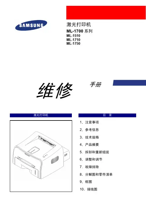
维 修激光打印机目 录1. 预防措施 2. 技术规格 3. 分解和组装 4. 故障检测 5. 分解图和部件列表 6. 电气部件列表 7. 框图 8. 接线图9. 印刷电路板(PCB )图 10. 原理图三 星激光打印机ML-4500/XEU ML-4500/DSG手册4.维护与故障排除4-1 预防性维护下述循环周期为保养通用指南。
示例表用于平均每天接收与传输50份文件。
环境条件4-2打印质量第 1 页4-3 DCU(诊断器)控制4-3-1 DCU设置DCU用于诊断打印机故障。
使用DCU之前,首先打开并除去打印机前部出口盖,然后从左边除去底盖。
将DCU排插线(10针至4针)连接到控制板上的CN9(4针)。
4-3-2 状态代码将DCU连接到打印机上,然后打开电源。
DCU用7段发光二极管显示状态代码。
有两种状态代码:正常与错误。
状态代码表示打印机的运行状态。
正常状态代码错误状态代码4-3-3 诊断方式当打印机故障发生且DCU显示错误状态代码时,您可以使用诊断模式查找问题并进行修理。
诊断代码当您修理故障时,您可以仅使机器的一个单元在诊断模式下运行。
同时按下三个按钮([DOWN],[SHIFT],[STOP]),打开打印机电源,进入诊断模式。
当DCU显示‘78’,2-3秒后放开这些按键,接着DCU显示‘00’。
通过使用[UP]或[SHIFT]与[DOWN]键,选择适宜的诊断模式,然后按下[ENTER]键运行。
如欲停止运行,按下[SHIFT]与[ENTER]第 3 页4-3-4自测试按钮当您按下此按钮,机器打印‘竖行’样张。
当您按下此按钮并接通打印机电源,DCU显示代码‘89’,同时打印机预热。
预热之后,打印机处于‘准备’状态。
DCU显示代码‘88’。
在此模式下,所有传感器不运行,打印机进行所有打印操作(打印演示样张)与打印PC数据)。
如果诊断打印引擎有故障时的控制板,此模式非常有用。
希望以上资料对你有所帮助,附励志名言3条::1、世事忙忙如水流,休将名利挂心头。
55. Disassembly and Reassembly5.1 General Precautions on DisassemblyWhen you disassemble and reassemble components, you must use extreme caution. The close proximity of cables to moving parts makes proper routing a must.If components are removed, any cables disturbed by the procedure must be restored as close as possible to their original positions. Before removing any component from the machine, note the cable routing that will be affected.Whenever servicing the machine, you must perform as follows:1. Check to verify that documents are not stored in memory.2. Be sure to remove the toner cartridge before you disassemble parts.3. Unplug the power cord.4. Use a flat and clean surface.5. Replace only with authorized components.6. Do not force plastic-material components.7. Make sure all components are in their proper posi-tion.Releasing Plastic LatchesMany of the parts are held in place with plastic latches. The latches break easily; release them carefully.T o remove such parts, press the hook end of the latchaway from the part to which it is latched.5.2 Disassembly and Reassembly 5.2.1 Front Cover1.Open the front cover.(The front cover and the cas-sette tray are assembled with the same assembly.)2.Separate the cover from the lock of the frame by pulling the right bottom of the cover toward the arrow direction. Pull out the front cover to the left as shown as below.1.For separating only cassette tray,open the tray.2.Hold the set and lift up the hook on the left bottomtoward the arrow direction.Separate the cassette trayby pulling it out to the left as shown as below.5.2.2 Cassette Tray5.2.3 SMPS Cover5.2.4 Main Cover1.Release two screws.(Screw x2:Silver_M3,6003-000196)2.Separate the lock by holding the left side of the cover and pulling it toward the arrow direction. Remove it with carefulness that the power switch is not hooked on SMPS cover as shown as below.1.Before Disassembling.-Separate the font cover.(Refer to 5.2)-Separate the SMPS cover.(Refer to 5.3)2.Release 4 screws as shown as below.(Screw x 4 : Silver_M3,6003-000196)3.Hold the both ends of the cover and pull it up bit by bit toward the arrow direction as shown as below.4.Separate it by holding the both sides of the main cover and carefully lifting it up.5.If necessary,remove the jam cover.Open the cover, take out the hook on the right toward the arrow direc-tion, and then take out the jam cover to the right side.5.2.5 Top Cover1.Before Disassembling.-Separate the font cover.(Refer to 5.2) -Separate the SMPS cover.(Refer to 5.3) -Separate the Main cover.(Refer to 5.4)2.For separating the LED lens and the On-Line key, release the 5 screws connected to the main cover, and then 4 locks on the front and rear of the top cover by using a screw driver.Remove the top cover from the main cover.(Screw x 5:Silver_M3,6003-000196)3.Unscrew 2 screws from the separated top cover as shown as below,and then separate the LED Lens from the On-Line key.(Screw x 2:Silver_M3,6003-000196)5.2.6 HVPS1.Before Disassembling.-Separate the font cover.(Refer to 5.2)-Separate the SMPS cover.(Refer to 5.3)2.Remove the sheet by releasing the 5 screws which connects the HVPS and the Sheet.(Screw x 3:Gold_M3,6003-000269)3.Separate the HVPS with HVPS ground from the frame by releasing the remaining 3 screws.(Screw x 3:Gold_M3,6003-000269)4.Remove the connector from the separated HVPS.5.2.7 RX Drive1.Before Disassembling-Separate the font cover.(Refer to 5.2) -Separate the SMPS cover.(Refer to 5.3) -Separate the Main cover.(Refer to 5.4)2.Release 2 screws (Screw x 2:Silver_M3,6001-000130)connected to the engine shield and 6 screws (Screw x 6:Gold_M3,6003-000296)connected to the frame. Separate the RX drive by pulling it out toward the arrow direction.3.Remove the connector from the separated RX drive.Fuser Gear, and Feed Gear can be removed fromthe frame.5.2.8 Fuser5.When separating the motor,remove the motor brack-et first by removing 4 screws as shown as below, and then remove the 2 screws from the motor bracket.1.Before Disassembling-Separate the font cover.(Refer to 5.2)-Separate the SMPS cover.(Refer to 5.3)-Separate the Main cover.(Refer to 5.4)2.Separate 2 connectors from the SMPS and the Main PBA as shown as below.3.Separate the fuser by unscrewing 4 screws on the frame.(Screw x 4:Gold_M3,6003-000269)4.After removing the Lamp Cover L/R, separate the Fuser Dummy cover.5.Separate the Exit roller F/Down and the exit gear (DRV17)by turning the left/right holder connected to the exit roller F/Down to the arrow direction.At this time,roller_main,roller_FR, F/Down Holder,and spring are separated with theses.6.Remove the thermo cap by releasing 2 screws as shown as below.(Screw x 2:Black_M3,6003-000282)7.After pulling out the thermostat as shown as below,remove the CBF harness from its left/right side.8.Release the screw as shown as below, remove the harness from the cover, and then pull out the ther-mistor.(Screw x 1:Black_M3,6003-000196)9.After separating the CBF harness connected to the left/right side of the halogen lamp, release 2 screws from the halogen lamp.(Screw x 2:Black_M3,6003-000196)10.Separate the Cover-M by releasing 2 screws as shown as below.(Screw x 2 : Black_M3, 6003-000196)5.2.9 Engine Shield (Including Main PBA and SMPS)11.Remove the halogen lamp from the heat roller by pulling it out to the arrow direction.1.Before Disassembling-Separate the font cover.(Refer to 5.2)-Separate the SMPS cover.(Refer to 5.3)-Separate the Main cover.(Refer to 5.4)2.Disconnect all connectors except the connector which connects the SMPS to the Main PBA.3.Release 6 screws as shown as below, separate the harnesses from the shield,and then separate the engine shield with carefulness of the actuator feed sensor lever.(Screw x 6:Silver_M3,6003-000196)4.For removing only SMPS, perform the follows in order : separate the SMPS cover (Refer to the5.3),release 5 screws, separate the fuser connector and the main PBA connector, and then take out the SMPS.(Screw x 5 : Gold_M3, 6003-000269)5. For removing only Main PBA, perform the follows in order : separate the SMPS cover (Refer to the 5.3), release 3 screws, separate the main PBA connector, and then take out the main PBA.(Screw x 3 : Gold_M3, 6003-000269)5.2.10 LSU5.2.11 Paper Path Frame1.Before Disassembling-Separate the font cover.(Refer to 5.2)-Separate the SMPS cover.(Refer to 5.3)-Separate the Main cover.(Refer to 5.4)2.Release 3 screws as shown as below, lift up the LSU,and then disconnect 2 connectors from the separat-ed LSU.(Screw x 2:Silver_M3,6003-000196)1.Before Disassembling-Separate the font cover.(Refer to 5.2)-Separate the SMPS cover.(Refer to 5.3)-Separate the Main cover.(Refer to 5.4)-Separate the Fuser.(Refer to 5.8)-Separate the Engine shield.(Refer to 5.9)2.After releasing 4 screws as shown as below, take it out toward the arrow direction with carefulness of ground and harnesses.(Screw x 4:Silver_M3,6003-000196)3.After releasing the 2 hooks from the right side of theframe,take out the transfer roller.(Screw x 2:Silver-M3,6003-000196)4.Remove the solenoid-MP by releasing the screwfrom the left side of the frame.(Screw x 1:Gold_M3,6003-000301)5.2.12 Pick_Up Roller1.For separating the pick-up roller sponge, open thefront cover, and then take out the toner cartridge.2.While pressing the hooks on the left/right side of thepick-up housing B, pull out the pick-up housing U asshown as below.Then,replace the sponge.。