Perma自动注油器的型号和规格
- 格式:docx
- 大小:35.50 KB
- 文档页数:5

PERMA自动润滑系统手册亚普汽车部件有限公司一.公司使用的PERMA系列CLASSIC 系列 PRO C系列二.公司使用地点机械手移模机构CLASSIC系列 PRO C系列三.P ERMA自动润滑系统的优势1.CLASSIC系列相比手工加油更安全、更可靠、更省钱可控制可持续的自动供油在极小的间歇内注入微量的油脂高污染的环境下可以持续供给轴承新鲜的润滑油不需要外动力四个不同的排油时间透明的塑料端盖可以观察到油脂是否用完可以用一根软管连接注油器到润滑点,最远1米手工可以操作,无需工具2.PRO C系列注油时间由机器的控制系统控制能独立供应2-6个加油点直接与分配器相联接而没有压力损失去掉分配器可以当作单点注油器使用注油量可以调整到机器需求的注油量在机器的停机时间,注油器处于等待状态,开机再次开始继续注油通过PLC和注油器的LED信号显示来监视运行状态25bar高压能保证长距离注油3.与手工注油的比较四. P ERMA 结构CLASSIC 系列 PRO C 系五. 工作原理1.CLASSIC 系列将塑料反应环拧入加油器,直到圆环被拧断,环内的金属球被压入电解液里并发生化学反应。
化学反应产生气体,气体越多,压力越大,使活塞产生向前运动,润滑脂/油就会连续不断地被挤出注入到加油嘴里。
当润滑油用完时,出口端的塑料盖会看到活塞的红色,表明加油器内的脂/油已用尽,应该及时更换新的加油器。
2.PRO C 系列在驱动部分显示屏上设置释放周期等参数,通过连接电缆传送给分配器,驱动部分转动通过中间轴驱使油杯中的油受压,通过分配器均匀的分配到6根软管中,使润滑点均匀注油润滑。
(详细请参照同文件夹中的视频)六. 油释放的时间油杯驱动部分分配器1.CLASSIC系列拧入反应环和挤出润滑油之间的滞后时间,会因使用不同型号的加油器和不同颜色的反应环而有所不同。
使用不同颜色的反应环,出油时间就不一样:黄色-1个月,绿色-3个月,红色-6个月,灰色-12个月。

perma注油器使用手册摘要:一、前言二、perma 注油器简介1.产品概述2.型号及规格三、perma 注油器的使用方法1.准备工作2.操作步骤3.注意事项四、perma 注油器的维护与保养1.日常维护2.定期检查3.故障排除五、perma 注油器的储存与运输1.储存要求2.运输注意事项六、附录1.常见问题解答2.售后服务正文:【前言】perma 注油器是一款广泛应用于工业领域的设备,为了帮助用户更好地了解和使用perma 注油器,我们特别编写了本使用手册。
本手册将详细介绍perma 注油器的使用方法、维护保养以及储存运输等方面的内容,希望对您有所帮助。
【perma 注油器简介】perma 注油器是一种自动注油器,主要用于各类机械设备的润滑。
本产品具有注油精确、操作简便等优点,可有效降低设备故障,延长设备使用寿命。
【perma 注油器的使用方法】1.准备工作在使用perma 注油器前,请确保设备已安装完毕,并按照要求进行加油。
同时,请确保电源接通,且电源插头与设备电源插座相匹配。
2.操作步骤(1)将perma 注油器固定在需要润滑的设备上。
(2)根据设备润滑需求,设置注油量。
(3)打开电源开关,启动注油器。
(4)注油器将自动进行注油操作,注油完成后,设备将自动停止。
3.注意事项(1)请勿在油箱液面过低时使用perma 注油器,以免损坏设备。
(2)使用过程中,请勿堵塞注油口,以免影响注油效果。
(3)如发现注油器异常,请立即停止使用,并联系售后服务。
【perma 注油器的维护与保养】1.日常维护(1)定期检查perma 注油器的工作状态,如有异常,请及时处理。
(2)保持设备清洁,避免灰尘、油污等杂物进入注油器内部。
2.定期检查(1)检查注油器的油路是否畅通,如有堵塞,请及时清理。
(2)检查注油器的密封圈、O 型圈等部件是否完好,如有损坏,请及时更换。
3.故障排除如遇到注油器故障,请先关闭电源,然后根据故障现象,参考本手册或联系售后服务进行处理。
perma注油器使用手册【实用版】目录1.介绍 perma 注油器2.perma 注油器的使用步骤3.perma 注油器的维护保养4.安全注意事项5.结论正文perma 注油器是一种高性能的润滑设备,主要用于为机械设备提供持久、稳定的润滑。
它可以有效地减少摩擦,延长机械设备的使用寿命,提高设备的工作效率。
在这篇文章中,我们将详细介绍如何使用 perma 注油器,以及如何进行维护保养和安全注意事项。
一、介绍 perma 注油器perma 注油器采用先进的润滑技术,可以为机械设备提供最佳的润滑效果。
它具有以下特点:1.高效润滑:perma 注油器可以精确控制润滑油量,保证设备始终处于最佳的润滑状态。
2.持久润滑:perma 注油器采用特殊的润滑油,可以长时间保持润滑效果。
3.节省润滑油:perma 注油器可以根据设备的实际需要,精确控制润滑油的供给,节省润滑油。
4.安全环保:perma 注油器采用封闭式设计,可以防止润滑油泄漏,保护环境,避免润滑油对设备造成损害。
二、perma 注油器的使用步骤1.选择合适的 perma 注油器:根据设备的润滑需求,选择合适的型号和规格的 perma 注油器。
2.安装 perma 注油器:根据设备的安装位置和空间,选择合适的安装方式,安装 perma 注油器。
3.加注润滑油:打开 perma 注油器的加油口,加入适量的润滑油。
4.启动设备:启动设备,perma 注油器开始工作。
5.检查润滑效果:观察设备运行情况,检查润滑效果,如有异常,及时调整。
三、perma 注油器的维护保养1.定期更换润滑油:根据设备的使用情况和润滑油的质量,定期更换润滑油。
2.清洗 perma 注油器:定期清洗 perma 注油器,去除沉积的污垢和杂质。
3.检查密封件:定期检查 perma 注油器的密封件,如有损坏,及时更换。
四、安全注意事项1.使用前,请仔细阅读使用手册,了解 perma 注油器的使用方法和安全注意事项。
中国长期以来畅销最佳的注油器产品是三和波达机电科技有限公司,不仅给机器滋润,还给企业带来无限的实惠,如机器的使用时间,及机器的维修时间延长,可畅通使用机器。
Perma STAR-CONTROL数码加脂器为电动机驱动型,驱动器可重复使用,油杯为一次性使用,更换油杯时要同时更换电池,出油时间由外部7-30VDC的电源控制。
深圳三和波达机电科技有限公司自2011年以来一直致力发展专业国际品牌进口供应。
在系统网络上与香港、新加坡仓库连网。
备有大量原装现货,100%香港原装进口,质量保证!价格实惠!自动注油器具有如下特性:1、主动受控制式润滑管理,大量节省设备维修成本。
2、可避免溢出污染或断油之烦恼。
3、可保持润滑面持续新油供给。
4、按需要随时可停可续。
5、独特设计,防爆安全,安装灵活,简便,不受方向、位置限制。
优势:一、人力:1.可減少人力工时。
2.可按设备所需定时定量给予油脂。
二、金钱:1.降低购油成本。
2.维修设备费用可减少,3.增加设备的妥善率。
4.减少设备维修时间。
5.增加产能。
6.加速设备自动化。
综合传统人工保养方式与自动注脂器的特点比较,我们可以非常直观的看出自动注脂器的使用给机器设备使用用户直接带来收益。
俗语说预防胜于治疗,而在全球化的竞争下设备的妥善率既是企业的竞争力,增加产值就是增加利润,所以日常设备的维修保养是非常重要的,而保养首重润滑,确实的润滑可降低设备耗损,减少维修费用可减低企业营运资金,进而有更多的资金投入企业运转,创造更大的利润,所以使用自动注脂器既可节流又可开源,更是一个企业进步的象征。
应用领域:一、化学工业:1.化工原料、产品制造业。
2.造纸业。
3.塑(橡)胶制品制造业。
4.玻璃纤维原料、制品制造业。
5.染料、顏料、色料、芳香料制造业。
6.石化原料制造业。
二、工业机械:1.工具机,2.工作母机。
3.食品机械、纺织机械、输送机械、化工机械等。
4.工业设备及制品制造业。
5.电工器材制造业。
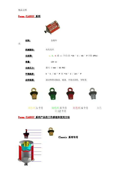
Perma CLASSIC系列材料:金属外壳机械驱动:电化反应出油期:1, 3, 6或12个月(在+20 °C / 68 °F下的 SF01)容量:120 cc出油压力:最大 4 bar / 58 PSI环境温度:0 °C / 32 °F 至+40 °C /104 °F应用范围:滚动和滑动轴承, 链条, 开放式齿轮, 导轨等.黄色环:1个月绿色环:3个月红色环:6个月灰色环:12个月Perma CLASSIC系列产品的工作原理和使用方法Classic 系列专用将塑料反应环拧入加油器,直到圆环被拧断,环内的金属球被压入电解液里并发生化学反应。
化学反应产生气体,气体越多,压力越大,使活塞产生向前运动,润滑脂/油就会连续不断地被挤出注入到加油嘴里。
当润滑油用完时,出口端的塑料盖会看到活塞的红色,表明加油器内的脂/油已用尽,应该及时更换新的加油器。
拧入反应环和挤出润滑油或脂之间的滞后时间,会因使用不同型号的加油器和不同颜色的反应环而有所不同。
使用不同颜色的反应环,出油时间就不一样:黄色-1个月,绿色-3个月,红色-6个月,灰色-12个月。
具体请参考下表。
不同型号的加油器所装润滑油或润滑脂的类型是不同的,SFxx(xx是数字,下同)代表加油器装的是不同的润滑脂,SOxx代表不同的润滑油,Gxxx或Sxxx代表客户特殊订制的加油器。
每只加油器底部的金属部分都会用钢印标出这只加油器的型号。
客户初次使用perma加油器前,我们会给您详尽的指导。
如果客户已经在使用perma 加油器,需要购买备件时,请提供您要的加油器的型号(如SF01)和规格(如红色反应环)这两种资料。
Perma Classic 系列产品的出油期注:以上数据为Perma-tec公司在实验室条件下得出的结果,只作选择出油期的一般参考。
实际的出油时间会受到很多因数的影响,例如:加油器所装的油品型号,加油点的背压和连接方式等。
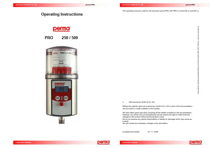
perma PRO perma PRO Operating InstructionsPRO 250 / 500This operating manual is valid for the lubricator perma PRO with PRO LC-units 250 cc and 500 cc.©2003 perma-tec GmbH & Co. KGWithout the specific approval of perma-tec GmbH & Co. KG no part of this documentation can be copied or made available to third parties.We have taken great care when compiling all the details contained in this documentation. However, we cannot rule out discrepancies and we reserve the right to make technical changes to the product without giving advance notice.We do not assume any judicial responsibility or liability for damages which may ensue as a result.We will include any necessary changes in the next edition.Compiled and printed: 18 / 11 / 2005 ©K o n z e p t i o n & G e s t a l t u n g A r b e i t s s i c h e r h e i t u n d D o k u m e n t a t i o n A R A , 4 8 1 6 7 M ün s t e r , w w w . a r a -m u e n s t e r . d eLubrication System perma PROQuick Reference Guide for the Lubrication Systemperma PROOn this page you will find some important information for quick and easy operation and setting of the perma PRO. Before the first installation of the perma PRO, and whenever you need detailed instructions, you should read the complete Operating Manual which contains information that must be observed. Make sure to follow the instructions given in the chapter “Safety Notes”.♦ Insert a new battery set into the battery compartment (follow directions of the arrows).♦ On the assembly plate, insert the contact pin in the correct slot for the PRO LC-unit that youintend to use (250 or 500).♦ Place the PRO LC-unit inside the cover and remove the plug of the PRO LC-unit. ♦ Push the PRO LC-unit into the cover until lubricant comes out of the opening. ♦ If necessary, mount the drive unit onto the mounting device and attach it with thethree pre-drilled holes. ♦ Place the PRO LC-unit with its cover on the drive-unit. Make sure that the catch locks and thatthe teeth of PRO LC-unit and drive unit interlock.♦ Turn the cover clockwise until the bayonet catch locks.♦ Hold down the ON/OFF/SELECT button until the …Remaining Volume“ appears in thedisplay and the green LED starts blinking.♦ Refer to the manufacturer’s guidelines about the lubrication point that you want to lubricate,in order to determine the required lubricant amount in cc per one hundred operating hours. ♦ Refer to chart 3 (chapter 6.7) and find your required lubrication amount. Based on that, thechart will show you the required PRO LC-unit size, the setting of the discharge period, and the setting mode.♦ You may also refer to our perma Select program which can be downloaded from our webpage free of charge. It helps you in selecting the correct settings.♦ Keep the MODE/SAVE button pressed until you have reached the Configuration Menu. ♦ Push the MODE/SAVE button as many times as it takes to reach the desired setting(Days, Weeks or Months).♦ When the display shows the correct setting mode, push the ON/OFF/SELECT buttonas many times as it takes to reach the desired discharge period.♦ Keep the MODE/SAVE button pressed until the display shows the …remaining volume“.♦ Keep the ON/OFF/SELECT button pressed until the display shows ("–– ") .Protection coverWith bayonet catch for quick opening/closing.PRO LC – Unit(Lubrication Canister) Cartridge, piston, spindle filled with lubricant.Red LEDindication.TypeProduct type and size of PRO LC-unit.ContentDescription of the contained lubricant and the filling date.DisplayInforms about operating conditions, malfunctions, settings, and thelubricant volume left in the PRO LC-unit..Push Button: ON/OFF/SELECTUsed to turn the unit on and off, and also to gradually increase the discharge period.(Jumper) To set the size Battery – Set Assembly of the perma PRO // Exchange of PRO LC-unit (refer to chapters 4 and 7)Starting the perma PRO (refer to chapter 6.5)Determine Discharge Period (refer to chapter 6.7)Setting the Discharge Period (refer to chapter 6.8)Save Settings (refer to chapter 6.8)Stopping the perma PRO (refer to chapter. 6.6)Table of ContentsThe lubrication system perma PRO 1Quick reference guide 2Content31. Various41.1 Deliveries 1.2 Storage 1.3 Markings 1.4 Intended Usage 1.5 Legal Requirements2. Safety Instructions62.1 Persons responsible for safety 2.2 General Safety Instructions 2.3 Safety Information for perma PRO3. Technical Data73.1 Design of the perma PRO Lubricator4.Mounting and Assembly of the Lubrication System 94.1 Mounting the Drive Unit onto a Fixing Device for Wall-Mounting 4.2 Assembly of the Lubricator5.Display and Control Elements of the Lubrication System 125.1 Display Elements 5.2 Function Indication on the Display 5.3 Function Indication via the LEDs 5.4 Control Buttons6. Operation and Control 136.1 Preparations 6.2 Prior to Operation 6.3 Setting into Operation 6.4 During Operation 6.5 Switching the Lubrication System On 6.6 Switching the Lubrication System Off 6.7 Determining the Discharge Period 6.8 Setting the Discharge Period 6.9 Calculation of the Remaining Discharge Period7.Replacement of the PRO LC-Unit 197.1 Setting the Volume of the PRO LC-Unit 7.2 How to Replace the PRO LC-Unit8. Trouble Shooting 218.1 Error Messages on the Display 8.2 Trouble Shooting Guide9.Accessories and Spare Parts2210. Disposal2411. Service24perma-tecGmbH & Co. KGInternet: e-mail: info@1. VariousAbout this Operating Manual♦ This operating manual is intended for the safe operation of the perma PRO automatic lubricator.It contains safety instructions which must be adhered to.♦ Everyone who works on or with the lubricator must have access to this operating manual during theirshift. They must also pay attention to all relevant instructions and notices.♦ The operating manual must always be kept complete and in easy to read condition.Terms Used♦ Lubricator perma PROIn the following text, the “lubricator“ will either be called “lubricator“ or by its name “perma PRO“.♦ Lubrication CanisterIn the following text, the “Lubrication Canister“ will be called PRO LC-unit. The user can order the PRO LC-unit with different lubricants and in size 250 cc and 500 cc.Usage of Safety InstructionsAll safety instructions in this operating manual are standardized.Danger SignsThis sign warns you of any danger to people’s health or to subjects.This sign alerts you to application tips which will help you in doing certain tasks quicker and safer.1.1 Delivery / Content♦ perma PRO will be delivered according to customer specifications in regards to type of grease and sizeof PRO LC-unit.The user must only assemble it and adjust the desired settings.♦Mounting device and screws included.♦ Operating instructions and EC Conformity Declaration included.Upon delivery, make sure to check if the delivered goods correspond to your order. perma-tec GmbH & Co. KG will not accept liability for subsequent claims of any shortcomings. ♦ Please immediately forward any claims:of noticeable transport damage: directly to the forwarder.of noticeable faults, shortcomings or defects: directly to your perma distributor.1.2 StorageWhen the lubricators are not immediately installed, you must ensure appropriate storage conditions in dry, dust free places with a temperature of +20°C ±5° C (+68°F ±9°F).Please make sure that the cover disc (2) with plug (3) on PRO / PRO C drive units (1) is never removed for a longer period since this will cause the internal support battery to empty prematurely.Remove the cover disc only right before you intend to use the lubricator.Extended storage periods without cover disc/plug or without an PRO LC unit should be avoided.12.Conformity Declaration for perma PROEC – Conformity DeclarationAccording to the Machinery Directive 98/37/EC and according to EMV (Electromagnetic Compatibility) – Directive 89/336/EWG.The manufacturerperma-tec GmbH & Co. KG Hammelburger Straße 21D – 97717 Euerdorfhereby declares that the product as described in the given statement conforms to the regulationsappertaining to the directives referred to above, including any amendments thereto which are in force at the time of the declaration.Product description: Automatic lubricator Product name: Lubricator perma PROType: perma PRO 250 and perma PRO 500The following harmonised standards were applied:EN 292 – 1: 1991 Safety of machinery – basic concepts, general terms of reference as regards design and construction– Section 1: Basic Terminology, MethodologyEN 292 – 2:1991Safety of machinery – basic concepts, general terms of reference as regards design and construction– Section 2: Technical terms of reference and specificationsEN 60204 – 1:1998 Machinery’s electrical equipmentEuerdorf, 09 December 2002perma-tec GmbH & Co. KGPeter Mayr, Managing Director Dr. Michael Weigand, Technical ManagementThis declaration certifies conformity to the directives referred to but it is not a warranty of qualities. The safety instructions of the operating manual are to be observed.(3(2)10. DisposalHelp us in protecting the environment and saving resources by recycling valuable raw material. Please follow your local waste disposal regulations.11.Service♦ Please contact your local supplier for availability and cost of the following:Returning of the empty lubricator for environmentally safe recycling or disposal.or:exchange of battery set. exchange of PRO LC-unit.setting the desired discharge period.1.3 Markings♦ The lubricator perma PRO is clearly marked with a label on the drive system and a label on the PROLC-unit.♦ CE mark on the drive unit and the PRO LC-unit.♦ Manufacturer:perma-tec GmbH & Co. KG Hammelburger Straße 21 D – 97717 EuerdorfInternet: e–mail: info@1.4 Intended UsageThe lubricator perma PRO♦ Immediately supplies all lubrication points with lubricant, at a pressure build-up of max. 25 bar (360psi.), permanently, precisely and independent of temperature.♦ Can be used for all lubrication points of sliding- and roller bearings, drive- and transport chains,sliding guideways, open gears and seals.♦ Should only be connected to/used with original lubrication tubes from perma-tec GmbH & Co. KG. ♦ Is intended for use on machinery and equipment.♦ Is only to be used for the ordered purpose and purposes confirmed by perma-tec. ♦ Is only to be used for operating conditions recommended in this operating manual. ♦ Is only to be used with settings and variations recommended in this operating manual.Any other usage, setting, addition, and variation is considered to be inappropriate!1.5 Legal RequirementsLiability♦ The information, data and tips stated in this operating manual were up-to-data as of the printing date.No claims for already delivered lubricators perma PRO can be made based on the information, pictures and descriptions♦ perma-tec GmbH & Co. KG can not be held liable for damages and malfunctions caused by:inappropriate usage;unauthorized alterations to the drive system or the PRO LC-unit; inappropriate operations on or with the lubricator; incorrect operation and settings of the lubricator; incorrect settings of time and size of the lubricator; ignoring the operating manual.Warranty♦ Warranty terms and conditions: see terms and conditions of sale and delivery appertaining to perma-tec GmbH & Co. KG.♦ Lodge any warranty claims with your local supplier immediately after the defect or error has beenidentified.♦ The warranty expires in all instances where no liability claims can be enforced.2.Safety Instructions2.1Persons responsible for safety♦ The operator or his safety officer must warrant,that all the relevant regulations, instructions and laws are adhered to; that only qualified personnel will work with and on the lubricator;that unauthorized personnel are not allowed to work with and on the lubricator;that the safety regulations are adhered to when mounting the lubricator or during maintenance.2.2 General Safety Instructions♦ We are not laying claim to completeness in regards to these safety instructions. Please contact perma-tec Customer Service if you have any questions or problems.♦ At the time of delivery the lubricator is in line with state-of-the-art technology and in principle isconsidered to be safe to operate.♦ Dangers emanate from the lubricator for persons, the lubricator itself and for other material assets of theoperator if:unqualified personnel operates the lubricator;the lubricator is used inappropriately and for operations that it was not intended to be used for; the lubricator setting / variation is incorrect;the lubricator is opened by force while in operation;the lubricator is not mounted with the perma mounting device;the tube connection to the lubrication point was not carried out and attached correctly; ♦ Operate the lubricator only when it is in perfect condition.♦ Retrofitting, changing, or reconstructing the lubricator is prohibited. perma-tec must be consulted first. ♦ Only original tube connections and connectors from perma-tec can be used on or with the lubricationsystem since these will withhold high pressures of up to 25 bar (360psi).♦ Ambient media, especially chemically aggressive substances, can attack seals and plastic.2.3 Safety information for perma PRO Safety during Installation and Maintenance♦ Ensure that all workstations and traffic routes are clean and safe!♦ Ensure that the relevant regulations and guidelines are adhered to when the installation or maintenancework is carried out in places where danger of falling exists.♦ Ensure that the relevant safety and operating instructions are observed when the lubricators are installedor serviced on machines or in factories (i.e. to Stop the machine).Safety When Handling the PRO LC-Unit♦ Avoid contact of lubricant with eyes, skin, and clothing! ♦ Avoid swallowing of lubricant!♦ Prevent lubricant from getting into soil or sewer system! ♦ Observe safety data sheets of lubricants!♦ Lubricant on traffic ways will increase the danger of slipping! Therefore, immediately clean lubricant fromfloors with special cleaner.♦ Only use original PRO LC-units from perma-tec!Safety when Handling Batteries!♦ Avoid contact of battery substances with eyes, skin and clothing! ♦ Avoid swallowing any leaking battery substances! ♦ Observe safety data sheets for batteries!♦Do not expose batteries to extreme heat and do not throw into open fire!♦ Do not recharge batteries!♦ Ensure that regulations for waste disposal of batteries are observed! ♦ Only use original battery sets from perma-tec!Table 5 bSpare partsPart No. Illustrationperma PRO mounting device27.008.007400 g grease cartridge for pre-lubrication with grease press filled with SF 04400 g grease cartridge for pre-lubrication with grease press filled with other lubricants on requeston requestStraight connecting piece G 1/8 for lubricant tubes27.008.010Angle G 1/8 for connecting a lubricant tube27.008.011Special lubricant tube with different lengths27.008.009Reducer G 3/8 – G 1/4on requestCD ROM with SELECT software (calculation of the lubricant amount), lubrication and maintenance schedule and operating instructions as PDF fileon request9.Accessories and Spare PartsDue to the high pressure of up to 25 bar, you should only use genuine spare parts and accessories from perma-tec in order to ensure a reliable operation of the lubrication system. This especially applies to lubricant tubes.Spare parts and accessories must meet the technical requirements!This is always guaranteed with genuine spare parts and accessories from perma-tec.3. Technical DataTable 1Application area for out of specification range standard grease No warranty!The dashed standard grease- and dotted low temperature-lines show the maximum values allowed.If your application is out of the specification range shown in this diagram, please contact your local distributor. perma-tec cannot be held liable for these applications. Example:1. The application temperature is +5°C / +41°F. What is the maximum tube length allowed for standard grease?Correct Answer: 3m max. tube length for standard grease, 5m max. tube length for low temp. grease (arrow 1 meets the dashed line of the standard grease range at 3m)2. You want to use a 4m tube. Up to which temperature can the system be used?Correct Answer: +10°C/50°F with standard grease -5°C/23°F with low temp. grease (arrow 3 meets the -20°C-10°C 0°C 10°C 20°C 30°C 40°C50°C60°C 0°F20°F 40°F 60°F 80°F100°F 120°F140°FPRO 250 PRO 500 Volume of the PRO LC-unit 250 cc 500 cc Length (L) 210 mm 260 mm Diameter (D) 92 mm 92 mm Weight, empty1.30 kg 1.37 kg Weight, filled with SF04 1.53 kg 1.82 kg Discharge period1 day to 24 months1 day to 12 monthsDischarged volume per lubrication impulse 0.5 ccApplication temperature -20° C to +60 °C / -4°F to +140°FMaximum pressure build-up25 bar / 360 psiMaximum tube length (inner-Ø 5mm) 5 mLubricantsGreases up to rated consistency NLGI 2C ombination of these Maximum-Values can only be realized by temperatures of ≥20°C/ 68°F. At lower temperatures, the application is limited accordingto the diagram below.Power supply (0° C to +60 °C / +32°F to +140 °F)Battery set PRO B (3 V alkaline manganese, not rechargeable)Power supply, low temperature (-20°C to +60°C / -4°F to +140°F) Battery set PRO B PLUS (3 V lithium, not rechargeable)Connection thread G 3/8 outside – G1/8 insideProtection class IP 54D LFigure 1T e m p e r a t u r e i n °Ctube length in meterT e m p e r a t u r e i n °FSpare partsArt. No. IllustrationPRO LC-unit (250 cc) filled with special lubricant SF 04PRO LC-unit (250 cc) filled with other lubricants2220004608on requestPRO LC-unit (500 cc) filled with special lubricant SF 04PRO LC-unit (500 cc) filled with other lubricants2230004609on requestProtection cover 250 cc made of transparent plasticProtection cover 250 cc made of aluminium for applications with ester-containing lubricants22991010002299102001Protection cover 500 cc made of transparent plasticProtection cover 500 cc made of aluminium for applications with ester-containing lubricants 22991020002299102002Battery set B(0° C to +60° C / 32°F to 140°F)2299001606Battery set B PLUS(-20° C to +60° C / -4°F to +140°F)22990026073.1 Design of the perma PRO LubricatorLubricators are available as 250 cc and 500 cc versions and they can be supplied with the lubricant requested by the customer. They consist of (refer to figure 2): 8. TroubleShooting8.1 Error Messages on the DisplayPossible errors of the lubrication system are detected by the electronic control system andare indicated on the display. If an error is displayed, the system is switched off until the cause of the error has been eliminated and the error message has been acknowledged.Error messages are acknowledged and reset by pushing the ON/OFF/SELECT button.8.2 Trouble shooting guideIf there are malfunctions during the operation of the lubrication system, please check for possible causes using the following table (refer to table 4). If you have to deal with a malfunction that is not listed in the table below, please contact your local supplier for technical support.Every time that an error message is displayed, the red LED is also blinking.Table4Indicationof thedisplayError Possible cause Remedial measuresE I Lubricator has been switchedoffExcess motor current of thelubricator motor due to ablocked outletBattery set is emptyClear the blockage andacknowledge the fault bypushing and holding down theON/OFF/SELECT button.Insert a new battery set anduse a full PRO LC-unit.E4 Lubricator has been switchedoffDrive mechanism is defective. Exchange the drive unit.LC System does not detectthe PRO LC-unitSignal of the jumper is notfoundNo PRO LC-unit installedJumper has not been insertedcorrectly or is missingInstall an PRO LC-unit.Insert the jumper in thecorrect slot for the PRO LC-unit size that you intend touse.L o No power supplied to thesystem from the batteryNo battery inserted or batteryset emptyInsert a new battery set anduse a full PRO LC-unit.7.2 How to Replace the PRO LC-Unita) Turn the protection cover on the drive unit counter-clockwise and remove it.b) Remove the empty PRO LC-unit. The display indicates “LC“ and the red LED is blinking.c) Remove the used battery set from the drive unit. The display indicates “L O“.d) Insert the new battery set into the drive unit. Follow the directions of the arrows. The displayindicates “LC“ again.e) Remove the plug of the PRO LC-unit.f) Push the PRO LC-unit into the protection cover until lubricant comes out of the opening.(refer to figure 6, chapter 4).g) Place the new PRO LC-unit on the drive unit, turn it until the catch locks and the teeth of the PRO LC-unit and the drive unit interlock. The control system automatically recognizes the new PRO LC-unit.The display indicates "–– " if the perma PRO was switched off prior to the replacement of thePRO LC-unit. Or it indicates "99 % Vol.“ if the perma PRO was switched on before the replacement.You should only use completely full perma-tec PRO LC-units, in order to guarantee a trouble-freeoperation.h) The lubrication system continues to operate with the previous setting of the discharge period.i) If necessary, change the discharge period of the lubricator (refer to chapter 6.8).The discharging process automatically starts using the previous settings of the discharge period if the lubricator was switched on prior to the replacement of the PRO LC-unit.If the lubricator was previously switched off, the discharging process must be started by pushing the ON/OFF/SELECT button. (refer to figure 13, chapter 6.5) 4. Mounting and Assembly of the Lubrication System4.1 Mounting the Drive Unit onto a Fixing Device for Wall-Mounting♦Attach the supplied mounting device to the drive unit using the two enclosed hex head bolts (M6 x 16) and the two washers.♦Screw the mounting device with the drive unit onto a support of your system.For the position of the bores of the three fixing screws (141.5 x 45) refer to figure 3 below. You haveto use at least three hexagon screws M6 x 25.♦Before you connect the outlet of the drive unit to the lubricant tube, you have to make sure that the lubrication points and the complete lubricant tube is pre-lubricated with the same lubricant that iscontained in the PRO LC-unit. For that, perma-tec offers a 400 g lubrication cartridge for manually-operated grease presses with the requested lubricant.♦Connect the lubricant tube (connection G 3/8 outside or G 1/8 inside) to the outlet of the drive unit and install the tube correctly between the outlet and the lubrication point. The lubricant tube must notbe longer than five meters.M ake sure that you assemble the connections and lubricant tubes correctly and tightly to avoid possible leakage.Figure32 hex head boltsM6 x 16, maximumtorque 3 Nm (suppliedfor attaching theperma PRO to themounting device)Hexagon screwsM6 x 25(for wall mounting)2 hexagon screwsM6 x 25(for wall mounting)4.2 Assembly of the Lubricatora)♦ Insert the battery set into the drive unit (according to the direction of the arrow on the label). ♦ Check the position of the jumper, which has to correspond to the size of the PRO LC-unit(refer to figure 4 and chapter 7.1).Figure 4b)♦ Place the PRO LC-unit inside the protection cover and remove the plug of the PRO LC-unit(refer to figure 5).7. Replacement of the PRO LC-UnitThe Following Must Always Be Taken into AccountIf the replacement of an empty PRO LC-unit becomes necessary, it will be indicated by a simultaneous blinking of the red and the green LED. Additionally, the display indicates that the PRO LC-unit is empty (refer to figure 21).Figure 21If you replace the PRO LC-unit, you also have to change the battery set. Otherwise, the correct operation of the lubricator cannot be guaranteed!If you replace the PRO LC-unit by an PRO LC-unit of a different size, a corresponding protection cover (refer to table 5a, chapter 9) must be used.After the installation of the new PRO LC-unit, the control system continues to operate using the previously valid setting of the discharge period.7.1Setting the Volume of the PRO LC-UnitYou have to set the size of the PRO LC-unit by inserting the contact pin (jumper) into the base plate ofFigure 22Since the drive unit and the control board must be protected against moisture, an exchange may only be carried out in dry conditions!Attention!If an PRO LC-unit has been removed from the lubricator and another PRO LC-unit has been installed, the control system always assumes that this PRO LC-unit is new and full. Therefore you should never use an PRO LC-unit if it is not completely full!Setting 250 ccSetting 500 ccCatchInterlocking teethJumperContact pin (jumper)Plugged-in jumper for size 250 ccJumperBattery setProtection cover PRO LC-unit PlugLow-Temperature Cut-Off of the Lubrication SystemThe temperature range from 0° C to -19° C ( 32°F to –2.2°F) is indicated by a blinking ice crystal symbol (refer to figure 20).In this temperature range the lubrication system perma PRO continues to operate without interruption. Please note, that in this temperature range an additional discharge is not possible!Figure 20 Display with a blinking ice crystal (in this example with 89 % Vol.)In order to protect the system from damage, the low-temperature cut-off of the lubrication system isautomatically carried out by the control system and the built-in temperature sensor.If the temperature reaches or falls below -20°C (-4°F), the lubricator is switched off by the low-temperaturecut-off and the ice crystal symbol is permanently indicated on the display. The remaining volume is stilldisplayed in % Vol.From this time onwards, the lubricant is no longer discharged. You have to take this fact intoaccount if your system continues to operate in order to prevent damages!As soon as the temperature rises and reaches -19° C (-2.2°F) or higher, the control systemswitches the lubrication system on again.The display shows the remaining volume and the blinking ice crystal symbol.All discharges (except additional discharges), accumulated during the shut-off, will be caught upwhen the system continues operation (at a max. of two additional discharges with every regulardischarge).6.9 Calculation of the Remaining Discharge PeriodPlease note, that in case of one or several additional discharges, the remaining discharge period of thelubrication system must be recalculated. This also applies in case of a cut-off of the lubrication systemdue to a long machine standstill (e.g. weekends or annual holidays) or in case of a low-temperaturecut-off carried out by the system if temperatures reach -20° C (-4°F).You should also note the result of your calculation of the remaining discharge period in your lubricationand maintenance schedule.Formula: R DP =100RV*SDPSDP: Set Discharge Period of the lubricator (days, weeks, months)RV: Remaining Volume (displayed in % Vol.)R DP: Remaining discharge period (days, weeks, months depending on SDP)Example of a Calculation of the Remaining Discharge PeriodThe perma PRO with a 250 cc PRO LC-unit was originally set to a discharge period (SDP) of eight months,since the lubrication point needs 4.3 cc lubricant /100 h. After two months, the perma PRO indicates aremaining volume (RV) of 75 % Vol. At this point, the lubricator is switched off for six weeks (e.g. machinestandstill). When it is switched on again, you would like to determine when the PRO LC-unit will be empty.R DP =100RV*SDP=10075*8=100600= 6This results in a remaining discharge period of six months. After these six months, the PRO LC-unit will beempty and must be replaced by a new one.c)♦Push the PRO LC-unit into the protection cover until lubricant comes out of the opening(refer to figure 6).Figure 6d)♦Place the PRO LC-unit with its protection cover on the drive-unit. Make sure that the catch locks andthat the teeth of the PRO LC-unit and the drive unit interlock (refer to figure 4 and figure 7).♦Turn the cover clockwise until the bayonet catch locks.F igure 7。
中国长期以来畅销最佳的注油器产品是三和波达机电科技有限公司,不仅给机器滋润,还给企业带来无限的实惠,如机器的使用时间,及机器的维修时间延长,可畅通使用机器。
Perma NOVA自动注油器系列为最新研发和生产的数显式电化学反应驱动型,由显示和设定单元和油杯组成,显示和设定单元可重复使用,油杯一次性使用。
Perma NOVA自动注油器显示和设定单元上带操作按钮和数字显示,可以设定出油期为1-12个月,并可显示工作状态。
Perma公司是世界上最大的自动注油器生产商,其全球市场占有率为80%。
而且Perma在研究和开发方面进行了大量的投资,拥有世界领先水平。
深圳三和波达机电科技有限公司自2011年以来一直致力发展专业国际品牌进口供应。
在系统网络上与香港、新加坡仓库连网。
备有大量原装现货,100%原装进口,质量保证!价格实惠!自动注油器具有如下特性:1、主动受控制式润滑管理,大量节省设备维修成本。
2、可避免溢出污染或断油之烦恼。
3、可保持润滑面持续新油供给。
4、按需要随时可停可续。
5、独特设计,防爆安全,安装灵活,简便,不受方向、位置限制。
优势:一、人力:1.可減少人力工时。
2.可按设备所需定时定量给予油脂。
二、金钱:1.降低购油成本。
2.维修设备费用可减少,3.增加设备的妥善率。
4.减少设备维修时间。
5.增加产能。
6.加速设备自动化。
俗语说预防胜于治疗,而在全球化的竞争下设备的妥善率既是企业的竞争力,增加产值就是增加利润,所以日常设备的维修保养是非常重要的,而保养首重润滑,确实的润滑可降低设备耗损,减少维修费用可减低企业营运资金,进而有更多的资金投入企业运转,创造更大的利润,所以使用自动注脂器既可节流又可开源,更是一个企业进步的象征。
应用领域:一、化学工业:1.化工原料、产品制造业。
2.造纸业。
3.塑(橡)胶制品制造业。
4.玻璃纤维原料、制品制造业。
5.染料、顏料、色料、芳香料制造业。
6.石化原料制造业。
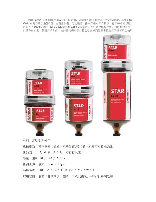
德国Perma自动加脂(油)器,可以自动地,定量地给所有润滑点加注油或油脂。
其中Star Vario系列自动加脂(油)器,由电池供电,电机驱动,指示灯指示工作状态。
有三种不同容量的油杯(S60-60毫升,M120-120毫升和L250-250毫升)可供选择配套使用。
可自行设定出油量和出油期,使用灵活方便,出油量精确可靠,特别适合对润滑要求特别高的机械设备使用材料: 透明塑料外壳机械驱动: 可重复使用的机电驱动装置,带齿轮电机和可更换电池组出油期: 1, 3, 6 或 12 个月, 可自行设定容量: 油杯 60 / 120 / 250 cc出油压力: 最大 5 bar / 75psi环境温度: -10 °C / 14 °F 至+50 °C / 122 °F应用范围: 滚动和滑动轴承, 链条, 开放式齿轮, 导轨等.特别适用于需要高出油压力和快速反应建压出油, 以及环境温度高和变化的环境.特征: 油杯 (润滑油筒) 可就地更换,耐腐蚀,电驱动装置可重复使用. 带保护盖, 可以防水和防尘等...STAR VARIO系列加油器分三部分:驱动装置,电池和油杯。
驱动装置由带开关的后端盖,控制电路板(带红/绿指示灯),电池组,驱动电机,减速装制和螺杆接头等组成;油杯由塑料外壳,活塞,螺杆和润滑油/脂组成。
打开开关,电机定时转动,带动螺杆转动,螺杆带动活塞向前运动,将油或脂压出油杯。
使用时将驱动装置和油杯拧接在一起,打开后端盖,装入电池组(注意箭头标志朝向加油器)。
在电路板上有两组微型拨动开关用于设定出油期和选择配用油杯的规格(详见下表1),设定好出油期后盖上端盖,将整个加油器拧入加油咀上。
将端盖上的开关拧到ON的位置,红色指示灯亮,同时听到电机的嘀哒响声,表明加油器已经开始正常工作。
绿灯闪亮(每15秒),系统正常;红灯闪亮(每8秒),系统错误;绿/红灯闪亮(每3秒),油杯用完,需要更换新的油杯和电池;红灯亮,正常出油。

QMA/QPMA 型油枪点 火 装 置用户手册美国FORNEY公司中国工程服务中心目 录一、简介 (2)二、QMA/QPMA型油枪 (3)三、HESI高能点火器 (9)一、简介美国Forney公司的QMA/QPMA型油枪作为点火装置,采用机械雾化,每套QMA/QPMA型油枪包括以下部件:安装管油枪枪体(含雾化器组件)油枪枪体导管(附带耐热不锈钢稳燃罩)油枪机构导管及推进装置、电磁阀、限位开关、接线盒高能点火枪及推进装置、电磁阀、限位开关专用高压电缆高能点火器进油不锈钢金属软管二、QMA/QPMA 型油枪1. 概述QMA/QPMA 型油枪(见图1所示)能够有效雾化燃油稳定着火。
雾化可以通过一定压力下的燃油实现;因此称之为机械雾化(MA),并与所需的燃油类型相匹配。
1. 油枪2. 安装管 3. 油枪导管 4. 推进气缸 5. 限位开关 6. 机械手 7. 油金属软管124567图1 QMA/QPMA 型油枪这种油枪适用于平衡通风锅炉或正压锅炉。
标有“P”字母的燃烧器安装在正压锅炉上(如QPMA)。
安装在正压炉上的油枪应带有专用的隔板,以防止抽取油枪时高温烟气由安装管与油枪接口处喷出,即QMPA型油枪配有隔板或抽吸装置。
除非有特定的说明,本说明书中的相关内容适用于平衡通风锅炉或正压锅炉。
2. 简介这种油燃烧器由油枪枪体、安装管、导管和执行机构(驱动装置)以及限位开关组成。
枪体由油枪尾部接头、枪管以及雾化装置组成。
QMA机械式雾化油枪由刚性刚管组成。
QMA挠性油枪则带有一段同径金属软管。
油枪尾部接头引导燃油进入枪管、分油嘴、雾化片,分油嘴、雾化片由顶端螺母固定在枪体上。
执行机构(驱动装置)固定在油燃烧器的安装管上,通过一个机械手抓紧油枪导管,使导管移动从而带动安装在其内的油枪枪体进退。
可快速拆卸的卡箍在油枪枪体的尾部,能够保证油枪枪体与油枪导管的紧密结合,并且使油枪能够在短时间里完成拆卸,松动螺杆后将卡箍拿掉就可将油枪枪体退出来。
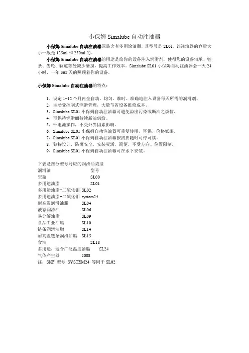
小保姆Simalube自动注油器小保姆Simalube自动注油器原装含有多用涂油脂,其型号是SL01,该注油器的容量大小一般是125ml和250ml的。
小保姆Simalube自动注油器的用途是给你的设备注入润滑剂,使得您的设备轴承、链条、齿轮、轨道等处减少磨损,提高工作效率。
Simalube SL01小保姆自动注油器会一天24小时,一年365天的照顾着你的设备。
小保姆Simalube自动注油器的特点:1、设定1~12个月内全自动、均匀、准时、准确地注入设备每天所需的润滑剂。
2、主动受控制式润滑管理,大量节省设备维修成本。
3、Simalube SL01小保姆自动注油器可避免溢出污染或断油之烦恼。
4、可保持润滑面持续新油供给。
5、干电池操作,不受外界因素影响。
6、Simalube SL01小保姆自动注油器可重复使用、环保,价格低廉。
7、Simalube SL01小保姆自动注油器按需要随时可停可续。
8、独特设计,防爆安全,安装灵活,简便,不受方向、位置限制。
9、Simalube SL01小保姆自动注油器可在水下安装。
下表是部分型号对应的润滑油类型润滑油型号空瓶SL00多用途油脂SL01多用途油脂+二硫化钼SL02多用途油脂+二硫化钼system24耐高温润滑油脂SL04液态润滑油SL06易分解油脂SL09食品工业油脂SL10链条润滑油脂SL14耐高温链条润滑油脂SL15食油SL18多用途,适合广泛温度油脂SL24气体产生器5008注:SKF 型号SYSTEM24 等同于SL02其它产品:1、轴承定量加脂机2、输送机托辊定量加脂机3、小保姆Simalube自动注油器4、轴承定量注油机5、Simalube SL01小保姆自动注油器6、电动油泵7、汽车轴承定量注脂机8、电动工具定量注脂机9、电钻定量注脂机10、汽车轴承定量加脂机11、汽车流水线自动注脂机12、汽车轮毂定量注脂机13、汽车盘毂总成自动加脂机14、铁路客车轴承定量注脂机15、铁路货车轴承三点式定量注脂机16、电机轴承定量注脂机17、Simalube SL01小保姆自动注油器18、小保姆Simalube自动注油器19、Simalube SL01小保姆自动注脂器20、小保姆注油器21、汽车轴承注脂机。
SIMALUBE注油器simalube250技术手册SIMALUBE主营产品:SIMALUBE润滑器、SIMALUBE润滑油、SIMATHERM感应加热器、SIMATOOL轴承安装工具等。
SIMALUBE自动注油器能够很容易地调节适合1到12个月的加油量,因此对每种润滑油脂的库存量很少。
此外还可以根据外界环境和润滑油使用情况来调节注油量。
对于长时间的停工,它还可以关闭和重新启动。
SIMALUBE自动注油器消除了日常手工给轴承加油的烦恼,这样维护成本可大大降低,而且润滑变得更简单。
SIMALUBE注油器30ml,60ml,125ml,250ml技术参数 SIMALUBE润滑油型号及参数: simalube250-SL01 Multipurpose grease–30/+120°C Mineral oil Li/Ca KP2K-30simalube250-SL02 Multipurpose grease + MoS2–25/+130°C Mineral oil Li KPF2K-20simalube250-SL04 High temperature grease–20/+160°C Mineral oil Be K2P-20simalube250-SL06 Fluid grease–20/+120°C Mineral oil Li/Ca GP0G-20simalube250-SL09 Biodegradable grease–20/+80/100°C Ester oil Li/Ca KPE2G-20simalube250-SL10 Food industry grease–30/+140°C Synthetic Al/comp KPHC2N-30simalube250-SL14 Chain oil–10/+90°C Mineral oil CGLP68simalube250-SL15 High temp. chain oil–30/+250°C Synthetic CGLPE220-320simalube250-SL16 Machine oil–20/+100°C Mineral oil CL68, HL68simalube250-SL18 Food industry oil–15/+150°C Synthetic CLPHC220simalube250-SL19 Biodegradable chain oil–15/+100°C Ester oilsimalube250-SL24 Wide temp. range。
T h e N e wG e ne r a ti o nThe Compact and RefillableSingle-Point Lubricator Swiss made / worldwide patentsThe new generation of simalube lubricatorsCartridge with gas producing drycells The dispensing period is infinitely variable and can be easily adjusted (1–12 months)3simalube can be filled as well as refilled by using a standard barrel pump that is typically used to fill grease guns.Universal applicationsimalube is available with a wide range of standard greases and oils.Customer specific lubricants can be used if suitable. The dispensing time on the simalube lubricator is variable between one and twelve months. The flexible delivery time gives the end user complete control over the amount of lubricant being applied.simalube delivers critical lubricant reliably throughout a temperature range of -20 to 55°C (-4 to +131°F).simalube is universally adaptable to most lubrication tasks through the use of the available accessory programme.Environmentally friendly and refillablesimalube is environmentally friendly as it does not contain any toxic liquids, batteries, motors, or gears.When exhausted, the simalube can either be recycled through standard recycling channels, or fitted with a new gas generating cartridge, easily refilled and put back into service.Standard lubricants Order Number4Dimensions and standard lubricantsFor further information on products and applications please request a simalube data sheet. You can find a list of simalube distributors at Applicationsø52 mm (2.05 in.)ø52 mm (2.05 in.)ø52 mm (2.05 in.)62m m (2.4i n .)100m m (3.9i n .)43m m (1.7i n .)186m m (7.3i n .)14m m (0.55i n .)R1/4”R1/4”R1/4”R1/4”simalube 30simalube 60simalube 125simalube 25014m m (0.55i n .)14m m (0.55i n .)14m m (0.55i n .)ø52 mm (2.05 in.)5Applications with simalube – accessoriesA comprehensive simalube accessory programme enables the simple application of simalube,the automatic single point lubricator.Adaptor for Perma clamp Chain lubrication with clampChain lubrication with round brush and two clampsChain lubrication with bracket, universally adjustableChain lubrication with lateral connection Lubrication of elevator guides or wire ropesRound brush with 90°connection4-fold adapter Art.2012Art. 2035Art. 2036Art. 2037Art. 2038Art.2010Art. 2014Art. 2010Art. 2034Art. 2013Art. 2035Art. 2036Art. 2037Art. 2038Art. 1045Art. 1046Art. 2800Art. 2035S Art. 2036S Art. 2037SArt. 1045Art. 1046Art. 2039Art. 2010Art. 2041Art. 1005Art. 4100Art. 4101WRONG!xProblematic due to different counter pressure!3-way bracketMounting support withprotective cover for simalubeArt. 2082Art. 2083Art. 2084Art. 2000Art. 2080Art. 2082Art. 2083Art. 2084Art. 2081Art. 2080Art. 1060Art. 2000simalube accessory programmeSubject to change without notice.simatec maintenance productsThe simatool product range is designed for a quick, precise and safe mounting and dis-mounting of bearings and seals. simatools are used around the globe in machinery repair and maintenance shops.The simatherm induction heaters provide fast warm-up of circular metal parts, for example bearings, for hot-mounting parts with an interference fit. Inductive heating of metal workpieces iscost-effecitve, time-saving and protects the environment. simatec is a global leader in thermal mounting technologies.6-25 World class lubrication, mounting and dismountingWith 3 products lines, simatec takes care of your critical machinery and plant operation to ensure maximum uptime.The automatic single point lubricator simalube can be adjusted from 1 to 12 monthsusing the unique gas-producing drycell that is patented world-wide. The drycell generates pressurethat pushes the grease or oil into the lubrication point.。
Pulsarlube M自动注油器产品介绍来自美国的高科技产品-Pulsarlube M自动注油器(帕尔萨自动注油器)。
Pulsarlube M自动注油器根据微处理器中存储的时间运行小型减速机,带动位于泵内部的蜗轮,通过立式活塞的往复运动吸入/喷出容器内润滑脂。
特点1、可任选注油周期。
单触即可选择1、2、3、6、12个月及15日(半月)喷油周期中自己希望的周期。
2、设定日期显示功能。
显示所选喷油周期及当前使用日数,便于肉眼观察。
3、亲环境性。
只要更换滑脂及电池盒,即能再次使用,从根本上防止环境污染。
4、止喷日期显示功能。
显示停止喷油日期,便于供油管理(搭载喷油日期保存功能)。
5、Pulsarlube M自动注油器差压诊断功能。
显示因供油量过多或管道阻力等差压过大而引起的供油受阻情况。
6、测试功能。
用于确认动作、急速喷油(清除)、电机负载诊断等各种目的。
7、供脂可靠性。
工作压力(20kgf/cm2)高,可适用于远距离安装。
8、Pulsarlube M自动注油器电池诊断功能。
显示电池容量状态,准确告知更换时间。
产品规格1、产品尺寸125cc:φ91×183(H)mm;250cc:φ91×210(H)mm2、滑脂容量125cc,250cc3、电池盒DC 4.5V(更换使用)4、使用温度条件-15℃~60℃5、工作压力20Kgf/cm26、Pulsarlube M自动注油器注油周期1、2、3、6、12个月及15日(H)7、安装规格3/8"PT8、喷油量(cc/stroke) 0.34cc 20℃(125cc);0.68cc 20℃(250cc)9、总行程数360次、125cc,720次/250cc注:随相对温度、热源(辐射热)情况等使用环境或滑脂种类,使用温度及喷油量可能存在差异。
适用对象* 空间狭窄,只能远距离安装的地方* 频繁发生高差压的地方* 发生巨大振动,不宜采用以往气体式产品的地方* 受灰尘或粉尘等污染后严重磨损轴承的地方* 需常注油,但不易注油的地方* 停机后才能注油的地方* 需减少维护费用的地方(如采用分配阀,可对2、4、6、8个注油点进行供油)* 需要注脂的所有工业用轴承类* 空调设备(集尘器、鼓风机)* 电机、泵类、回转设备* 传送带、各种机械设备* 大型大厦内回转、空调设备* 汽车工业、电子工业设备* 水泥工业、矿山设备* 造纸、纸浆工业* 饮食业* 炼铁、炼钢工业系列产品1、Pulsarlube-美国自动注油器①Pulsarlube MSP自动注脂器(MSP125 MSP250 MSP500)②Pulsarlube MS 自动润滑器(MS125 MS250 MS500)③Pulsarlube EX 自动润滑泵(EX125 EX250)④Pulsarlube C 单点润滑器(KLT100 KLT200)⑤Pulsarlube OL500自动注油器⑥帕尔萨自动注脂器-M (KLT125 KLT250)⑦电化学自动单点润滑器-Pulsarlube C (KLT100 KLT200)⑧帕尔萨自动注油器ML500 (Pulsarlube ML500)⑨Variable自动注脂器(KLT200C)⑩KLT1500自动注油器[弹簧式] (Pulsarlube S)2、A TS(ATS Electro-Lube International Inc.)-加拿大自动注油器①Micro-Luber自动注油器(60ml)②Mini-Luber迷你润滑杯(125ml)③Budget-Luber自动注脂器(250ml)④Jumbo-Luber自动润滑泵(475ml)⑤MD125电子自动注油器(125ml)⑥MD250电子自动注油器(250ml)⑦MD500自动加油泵(500ml)⑧ULT125电子自动润滑器⑨ULT250电动注油器⑩ULT500电动润滑泵。
perma注油器使用手册摘要:1.引言2.产品概述3.使用前的准备4.使用步骤4.1 准备工作4.2 安装油嘴4.3 加注润滑油4.4 拆卸油嘴5.注意事项6.常见问题及解决方法7.产品维护与保养8.结束语正文:【引言】PERMA 注油器是一款高效、便捷的润滑油加注工具,广泛应用于各种机械设备的保养维护。
本文将详细介绍PERMA 注油器的使用方法及相关注意事项。
【产品概述】PERMA 注油器是一种手动式润滑油加注器,具有结构简单、使用方便、加注量准确等特点。
适用于各种机械设备的润滑油加注,可以减少人工操作,提高工作效率。
【使用前的准备】在使用PERMA 注油器前,请确保润滑油已准备就绪,并检查注油器各部件是否完好无损。
同时,了解待加注设备的润滑油口位置,以便顺利进行加注操作。
【使用步骤】4.1 准备工作将PERMA 注油器上的油嘴安装到注油器主体上,确保油嘴与注油器主体的连接处紧密无松动。
4.2 安装油嘴将油嘴安装到待加注设备的润滑油口上,确保油嘴与润滑油口紧密贴合,避免油嘴滑脱。
4.3 加注润滑油扳动PERMA 注油器的手柄,将润滑油注入待加注设备。
在加注过程中,请保持油嘴与润滑油口的紧密贴合,避免润滑油泄漏。
4.4 拆卸油嘴加注完成后,松开油嘴与待加注设备的连接,将油嘴拆卸下来,妥善保管。
【注意事项】1.在使用过程中,请确保油嘴与润滑油口的连接紧密,避免润滑油泄漏。
2.加注润滑油时,请勿将手柄扳动过快,以免润滑油溅出。
3.请定期检查油嘴及注油器各部件的磨损情况,如有损坏,请及时更换。
【常见问题及解决方法】1.问题:润滑油加注不准确。
解决方法:检查油嘴与润滑油口的连接是否紧密,如不紧密,请重新安装。
2.问题:油嘴拆卸困难。
解决方法:使用适当的工具,如钳子等,辅助拆卸油嘴。
【产品维护与保养】1.使用后,请将PERMA 注油器及油嘴清洁干净,并妥善保管。
2.定期检查注油器的使用状况,如有异常,请及时联系售后服务。