AON2408规格书
- 格式:pdf
- 大小:380.03 KB
- 文档页数:5

at BPS4000 rev(yy/mm/dd)SupersedingDoc160-006AM040322BHTI Alternate Materials List M&P 299-947-100-690115BHTI Procurement Specification for Epoxy Adhesive, Heat Resistant M&P 299-947-320-820507BHTI Adhesive Film and Primer System, Intermediate CureTemperature (260-290º F) Service Temperature 67-225º F)M&P 68A900000G011101BAC Finish Spec: F-15M&P 74A900000E990308BAC Finish Specification for F18 Aircraft M&P 74A900004DG M051220BAC Ctrl: Fract Crit Parts, F-18M&P 74A901001F981208BAC Std Finish Codes: F-18 A\C M&P 901-947-002CA D950510BHTI Finish Specification for the V-22 Aircraft (Bell Boeing) Model901) EMD AircraftM&P A-A-208See Special Notes DL C120719FED Ink, Marking, Stencil, Opaque Use A-A-00208 in lieu of A-A-208.M&P A-A-2962Cancelled - no s/s spec A980810Cancel Notice 2FED Commercial Item Description Enamel, Alkyd, Exterior, SolventBased, Low VocOk to use canc spec.M&P A-A-3097DC-970506Notice 4FED Commercial Item Description Adhesives, Cyanoacrylate, RapidRoom Temperature-Curing, SolventlessM&P A-A-3165DE A071116FED Lacquer, Gloss, for A/C Use M&P A-A-00208See Special Notes DL D121001FED Commercial Item Description Ink, Marking, Stencil, Opaque(Porous and Non-Porous Surfaces)Use A-A-00208 in lieu of A-A-208.M&P A-A-52080B980523Notice 1FED Tape, Lacing, and Tying, Nylon M&P A-A-52081DF B980523Notice 1FED Tape, Lacing, and Tying, Polyester M&P A-A-52082DC D090817FED Tape, Lacing and Tying, TFE-Fluorocarbon M&P A-A-52083BJ C040223FED Tape, Lacing, and Tying, Glass M&P A-A-52084B980523Notice 1FED Tape, Lacing and Tying, Aramid M&P A-A-55829DC A110322DLA Acetic Acid, Glacial, Technical M&P A-A-56032CN D030521Notice 1FED Commercial Item Description (CIDS) Ink, Marking, Epoxy Base M&P A-A-59126-970926FED Terminals, Feedthru (Insulated) and Terminals, Stud (Insulatedand Noninsulated)ENG A-A-59132CR A100607Validation Notice 1DLA Amyl Acetate, Technical M&P A-A-59135CR-971028FED Commercial Item Description Packaging Material, Sheet M&P A-A-59136CR-971028FED Cushioning Material, Packaging, Closed Cell Foam Plank M&PA-A-59178DD A041012Notice 1USGOVT Nipple, Electrical Terminal ENGA-A-59503DC C110303FED Commercial Item Description Nitrogen, Technical M&PA-A-59551CP A091022USGOVT Wire, Electrical, Copper (Uninsulated) M&PA-A-59569DJ C090122Notice 1DLA Qualification Sampling and Testing of Steels for TransverseTensile PropertiesENG A-A-59588DJ B120130Notice 1FED Commercial Item Description Rubber, Silicone M&P A-A-59877CT-100909FED Commercial Item Description Insulating Compound, Electrical,EmbeddingM&P AIR4127CG - 071101SAE Steel: Chemical Composition and Hardenability M&P AISI-1010Unavailable-AISI Low Carb Stl Unavailable M&P AISI-50100Unavailable-AISI Bearing Stl Unavailable M&P AISI-52100Unavailable-AISI Bearing Stl Unavailable M&P AISI-B-1112Unavailable-AISI Low Carb Free Mach Stl Unavailable M&P AISI-C-1212Unavailable-AISI Material Spec, Stl Unavailable M&P AISI-C-1213Unavailable-AISI Low Carb Free Mach Stl Unavailable M&P AISI-C-1214Unavailable-AISI Material Spec, Stl Unavailable M&P AMS 2175CR A100601SAE Castings, Classification and Inspection of M&P AMS 2201Cancelled CN Can940901SAE Tolerances Aluminum and Aluminum Alloy Bar, Rod, Wire, andForging Stock Rolled or Cold-FinishedANSI H35.2M&P AMS 2221G060201SAE Tolerances, Copper and Copper Alloy Bars and Rods M&P AMS 2222BG J060201SAE Tolerances, Copper and Copper Alloy Sheet, Strip, and Plate M&Pat BPS4000 rev(yy/mm/dd)SupersedingDocAMS 2223BF H060201SAE Tolerances Copper and Copper Alloy Seamless Tubing M&P AMS 2224G060201SAE Tolerances Copper and Copper Alloy Wire M&P AMS 2241CN R070701SAE Tolerances, Corrosion and Heat-Resistant Steel, Iron Alloy,M&PTitanium, and Titanium Alloy Bars and WireM&P AMS 2242CC G080604SAE Tolerances Corrosion and Heat Resistant Steel, Iron Alloy,Titanium and Titanium Alloy Sheet, Strip and PlateAMS 2243DH K130601SAE Tolerances Corrosion and Heat-Resistant Steel Tubing M&PM&P AMS 2248DB G110301SAE Chemical Check Analysis Limits Corrosion and Heat-ResistantSteels and Alloys, Maraging and other Highly-Alloyed Steels,and Iron AlloysAMS 2249CN G090701SAE Chemical Check Analysis Limits Titanium and Titanium Alloys M&PM&P AMS 2259CN E071201SAE Chemical Check Analysis Limits Wrought Low-Alloy andCarbon SteelsAMS 2269CN F060501SAE Chemical Check Analysis Limits Nickel, Nickel Alloys, andM&PCobalt AlloysM&P AMS 2300CU L100801SAE Steel Cleanliness, Premium Aircraft-Quality Magnetic ParticleInspection ProcedureM&P AMS 2301CT K100801SAE Steel Cleanliness, Aircraft Quality Magnetic Particle InspectionProcedureAMS 2303CT F100801SAE Steel Cleanliness, Aircraft Quality, Martensitic CorrosionM&PResistant Steels Magnetic Particle Inspection ProcedureM&P AMS 2304CV B100801SAE Steel Cleanliness, Special Aircraft-Quality Magnetic ParticleInspection ProcedureM&P AMS 2310BE F060201SAE Qualification Sampling and Testing of Steels for TransverseTensile PropertiesAMS 2315DF G130201SAE Determination of Delta Ferrite Content M&P AMS 2350Cancelled - no s/s spec CN BA891001SAE Standards and Test Methods Ok to use canc spec.M&PM&P AMS 2355DB K110301SAE Quality Assurance Sampling and Testing Aluminum Alloys andMagnesium Alloy Wrought Products (Except Forging Stock),and Rolled, Forged, or Flash Welding RingsAMS 2360CN D070701SAE Room Temperature Tensile Properties of Castings M&PM&P AMS 2370DB K110601SAE Quality Assurance Sampling and Testing Carbon and Low-AlloySteel Wrought Products and Forging StockAMS 2371DB J110601SAE Quality Assurance Sampling and Testing Corrosion and Heat-M&PResistant Steels and Alloys Wrought Products and ForgingStockM&P AMS 2372DB F110601SAE Quality Assurance Sampling and Testing Carbon and Low-AlloySteel ForgingsAMS 2375CN D070601SAE Control of Forgings Requiring First Article Approval M&P AMS 2380CN F080601SAE Approval and Control of Premium-Quality Titanium Alloys M&P AMS 2400DG X130201SAE Plating, Cadmium M&P AMS 2401DF J130201SAE Plating, Cadmium Low Hydrogen Content Deposit M&P AMS 2403BM L041001SAE Plating, Nickel General Purpose M&P AMS 2404CH F081201SAE Plating, Electroless Nickel M&P AMS 2405DL E131001SAE Electroless Nickel Plate, Low Phosphorous M&P AMS 2406DE M121101SAE Plating, Chromium Hard Deposit M&P AMS 2408DL K130901SAE Plating, Tin M&P AMS 2410CR K100401SAE Plating, Silver Nickel Strike, High Bake M&P AMS 2411DM H131201SAE Plating, Silver for High Temperature Applications M&P AMS 2412CN J091201SAE Plating, Silver Copper Strike, Low Bake M&P AMS 2416CU L101201SAE Plating, Nickel-Cadmium Diffused M&P AMS 2417DL J130901SAE Plating, Zinc-Nickel Alloy M&P AMS 2418CU H110201SAE Plating, Copper M&P AMS 2419BM C030501SAE Plating, Cadmium-Titanium M&PM&P AMS 2420D021201SAE Plating of Aluminum for Solderability Zinc Immersion Pre-Treatment Processat BPS4000 rev(yy/mm/dd)SupersedingDocAMS 2423See Special Notes CE D020401SAE Plating, Nickel Hard Deposit Continue to use AMS-QQ-N-290 for Class 2Nickel.M&P AMS 2424CR F100401SAE NI Plate, Low Stressed Deposit M&P AMS 2426DL E130901SAE Coating, Cadmium Vacuum Deposition M&P AMS 2427DD D070701SAE Aluminum Coating Ion Vapor Deposition M&P AMS 2429CY D111001SAE Bronze Plate Masking M&P AMS 2430DB S120701SAE Shot Peening, Automatic M&P AMS 2432DF D130201SAE Shot Peening, Computer Monitored M&P AMS 2433C041001SAE Plating, Nickel-Thallium-Boron or Nickel-Boron M&P AMS 2434CY D110901SAE Plating, Tin-Zinc Alloy M&P AMS 2435Noncurrent CN G070601SAE Coating, Tungsten Carbide-Cobalt Coating, Detonation Process M&P AMS 2437BN C710111SAE Coating, Plasma Spray Deposition M&P AMS 2438CL D090701SAE Plating, Chromium Thin, Hard, Dense Deposit M&P AMS 2444BM A001201SAE Coating, Titanium Nitride Physical Vapor Deposition M&P AMS 2451CW C110701SAE Plating, Brush General Requirements M&PAMS 2460See Special Notes DF A130301SAE Plating, Chromium If dwg requires chrome plate per AMS-QQ-C-320then stress relief and embritlmnt (emb) bake reliefper BPS4620. If dwg req's chrome plate per AMS2460then stress relief and bake relief per AMS M&PAMS 2468Cancelled CN G981001SAE Hard Anodic Coating Treatment of Aluminum Alloys AMS 2469M&P AMS 2469DM J140201SAE Hard Anodic Coating Treatment of Aluminum and AluminumAlloys Processing and Performance RequirementsM&P AMS 2470DH N130701SAE Anodic Treatment of Aluminum Alloys Chromic Acid Process M&P AMS 2471DM H140201SAE Anodic Treatment of Aluminum Alloys Sulfuric Acid Process,Undyed CoatingM&P AMS 2472DD F070801SAE Anodic Treatment of Aluminum Alloys Sulfuric Acid Process,Dyed CoatingM&P AMS 2473DK H130801SAE Chemical Film Treatment for Aluminum Alloys General PurposeCoatingM&P AMS 2474Noncurrent DD D060201SAE Chemical Treatment for Aluminum Alloys Low ElectricalResistance CoatingAMS 2477M&P AMS 2477DD A100401SAE Conversion Coating for Aluminum Alloys Low Electrical Coating M&P AMS 2481CP J100201SAE Phosphate Treatment Antichafing M&P AMS 2482CN D100101SAE Hard Anodic Coating on Aluminum AlloysPolytetrafluoroethylene (PTFE)-Impregnated or CodepositedM&P AMS 2485BY K080101SAE Coating, Black Oxide M&P AMS 2486CR E100501SAE Conversion Coating of Titanium Alloys Fluoride-PhosphateTypeM&P AMS 2487CN A000301SAE Anodic Treatment of Titanium and Titanium Alloys Solution pH12.4 MaximumM&P AMS 2488D000606SAE Anodic Tr: Ti, Ti Alys M&P AMS 2515DE G130101SAE Polytetrafluoroethylene (PTFE) Resin Coating Low Build, 370 to400 °C (698 to 752 °F) FusionM&P AMS 2516DF E130301SAE Polytetrafluoroethylene (PTFE) Resin Coating High Build, 370to 400 °C (698 to 752 °F) FusionM&P AMS 2525DJ D130701SAE Graphite Coating, Thin Lubricating Film Impingement Applied M&P AMS 2526DE D130101SAE Molybdenum Disulfide Coating, Thin Lubricating FilmImpingement AppliedM&P AMS 2590DD-101201SAE Rotary Flap Peening of Metal Parts M&P AMS 2615BM F060901SAE Pressure Testing Hydraulic Pressure as Specified M&P AMS 2630CR C100101SAE Inspection, Ultrasonic Product Over 0.5 Inch (12.7 mm) Thick M&P AMS 2631CW D110701SAE Ultrasonic Inspection Titanium and Titanium Alloy Bar and Billet M&P AMS 2632BN A950301SAE Inspection, Ultrasonic, of Thin Materials 0.50 Inch (12.7 mm)and Under in Cross-Sectional ThicknessM&P AMS 2635Cancelled Can810701SAE Radiographic Insp ASTM E1742M&Pat BPS4000 rev(yy/mm/dd)SupersedingDocAMS 2640Cancelled CH Can960401SAE Magnetic Particle Inspection ASTM E1444M&P AMS 2645Cancelled CH Can950201SAE Fluorescent Penetrant Inspection ASTM E1417M&P AMS 2649DM D131201SAE Etch Inspection of High Strength Steel Parts M&P AMS 2658CN C091001SAE Hardness and Conductivity Inspection of Wrought AluminumAlloy PartsM&P AMS 2664CH F950701SAE Brazing, Silver for Use Up to 800 °F (427 °C)M&P AMS 2665DH H130501SAE Brazing, Silver for Use up to 400 °F (204 °C)M&P AMS 2666Cancelled Can840101SAE Ag Braz, High Temp AMS 2664M&P AMS 2670BK J060601SAE Brazing, Copper M&P AMS 2671Cancelled CH Can920101SAE Copper Brazing Corrosion and Heat Resistant Steels andAlloysAMS 2670M&P AMS 2672CY G120101SAE Brazing, Aluminum Torch or Furnace M&P AMS 2673DB E120101SAE Brazing, Aluminum and Aluminum Alloys Molten Flux (Dip)M&P AMS 2675DF H130201SAE Brazing, Nickel Alloy Filler Metal M&P AMS 2680C010601SAE Electron-Beam Welding for Fatigue Critical Applications M&P AMS 2681B000301SAE Electron Beam Welding M&P AMS 2685Noncurrent CP E071001SAE Welding, Tungsten Arc, Inert Gas GTAW Method M&P AMS 2689Noncurrent CH A980201SAE Fusion Welding Titanium and Titanium Alloys M&P AMS 2694DE C130101SAE In-Process Welding of Castings M&P AMS 2700DA E111101SAE Passivation of Corrosion Resistant Steels All acceptance testing shall be per Class 4except for Martensitic CRES alloy 440C,which requires no class testing.M&PAMS 2728DC C120901SAE Heat Treatment of Wrought Copper Beryllium Alloy Parts M&P AMS 2745CJ A071201SAE Induction Hardening of Steel Parts M&P AMS 2750DB E120701SAE Pyrometry M&P AMS 2753CF C080801SAE Liquid Salt Bath Ferritic Nitrocarburizing Non-Cyanide Bath M&P AMS 2755Cancelled CM Can090701SAE Nitriding, Molten Salt Bath Process not available, consider AMS 2753 asreplacement.M&P AMS 2759CE E081001SAE Heat Treatment of Steel Parts General Requirements M&PAMS 2759/1CJ E090201SAE Heat Treatment of Carbon and Low-Alloy Steel Parts MinimumTensile Strength Below 220 ksi (1517 MPa)Supersedes MIL-H-6875 for carbon & low-alloy steels below 220 ksi.M&PAMS 2759/2CR F100501SAE Heat Treatment of Low-Alloy Steel Parts Minimum TensileStrength 220 ksi (1517 MPa) and Higher Supersedes MIL-H-6875 for low-alloy steels,220 ksi & higher.M&PAMS 2759/3CE E080801SAE Heat Treatment Precipitation-Hardening Corrosion-Resistantand Maraging Steel Parts Supersedes MIL-H-6875 for precipitationhardening & maraging steel.M&PAMS 2759/4CA C080301SAE Heat Treatment Austenitic Corrosion-Resistant Steel Parts Supersedes MIL-H-6875 for austentic steels.M&P AMS 2759/5D040601SAE Heat Treatment Martensitic Corrosion Resistant Steel Parts Supersedes MIL-H-6875 for martensiticsteels.M&P AMS 2759/6BM B051101SAE Gas Nitriding and Heat Treatment of Low - Alloy Steel Parts Use Standard Drawing Notes per BDS2240.M&P AMS 2759/7CT B100501SAE Carburizing and Heat Treatment of Carburizing Grade SteelPartsM&PAMS 2759/8CG A070601See Special Notes SAE Ion Nitriding 1. Infrared pyrometry may be used to measuretemperature. 2. The nitriding temperature may beless than 50 degrees below the tempering or agingtemperature provided that the core hardness is notreduced. 3. for small loads, a minimum of twot t ti i b d i li M&PAMS 2759/9CL D090501SAE Hydrogen Embrittlement Relief (Baking of Steel Parts)Supersedes MIL-H-6875 for stress relievingsteels.M&P AMS 2759/10CN A060601SAE Automated Gaseous Nitriding Controlled by Nitriding Potential M&P AMS 2759/11BW-050401SAE Stress Relief of Steel Parts M&P AMS 2762Noncurrent CP B020101SAE Carburizing Carbon and Low-Alloy Steel Parts M&P AMS 2768CR C100701SAE Heat Treatment of Magnesium Alloy Castings M&P AMS 2769DD B091201SAE Heat Treatment of Parts in a Vacuum M&P AMS 2770DM L140501SAE Heat Treatment of Wrought Aluminum Alloy Parts M&Pat BPS4000 rev(yy/mm/dd)SupersedingDocAMS 2771DF E130201SAE Heat Treatment of Aluminum Alloy Castings M&P AMS 2772CW F110701SAE Heat Treatment of Aluminum Alloy Raw Materials M&P AMS 2774DC D121001SAE Heat Treatment Wrought Nickel Alloy and Cobalt Alloy Parts M&P AMS 2800CN D060801SAE Identification Finished Parts M&P AMS 2801B030301SAE Heat Treatment of Titanium Alloy Parts M&PM&P AMS 2807CF B080201SAE Identification Carbon and Low-Alloy Steels, Corrosion and Heat-Resistant Steels and Alloys Sheet, Strip, Plate and AircraftTubingAMS 3025CN C090901SAE Polyalkylene Glycol Heat Treat Quenchant M&P AMS 3106Cancelled Can830401SAE Primer, Adhesive, Corr Inhib AMS 3107M&P AMS 3107A910401SAE Primer, Adhesive, Corr-Inhibiting M&P AMS 3195CV F110501SAE Silicone Rubber Sponge, Closed Cell, Medium M&PM&P AMS 3216G050901SAE Fluorocarbon (FKM) Rubber High-Temperature - FluidResistant Low Compression Set 70 to 80AMS 3218C050901SAE Fluorocarbon (FKM) Rubber High-Temperature - FluidM&PResistant Low Compression Set 85 to 95M&P AMS 3276CB E080301SAE Sealing Compound, Integral Fuel Tanks and General Purpose,Intermittent Use to 360 °F (182 °C)AMS 3301DB H110601SAE Silicone Rubber, General Purpose, 40 Durometer M&P AMS 3305H900401SAE Silicone Rubber, Gen Purp, 75-85M&P AMS 3374DL D131101SAE Sealing Compound Aircraft Firewall, Silicone M&P AMS 3410J981001SAE Flux, Ag Braz M&P AMS 3411D981001SAE Flux Silver Brz, High Temp M&PM&P AMS 3644BL G060901SAE Plastic: Polyimide for Molded Rod, Bar, and Tube, Plaque, andformed PartsM&P AMS 3645CY D120101SAE Polychlorotrifluoroethylene (PCTFE), Compression MoldedHeavy Sections, UnplasticizedM&P AMS 3650CY D120101SAE Rods, Sheets, and Molded Shapes, Polychlorotrifluoroethylene(PCTFE) UnplasticizedAMS 3651Cancelled Can870401SAE PTFE AMS 3667M&P AMS 3651Cancelled Can870401PTFE AMS 3652M&P AMS 3651Cancelled Can870401PTFE AMS 3656M&P AMS 3651Cancelled Can870401PTFE AMS 3660M&P AMS 3652C930101SAE PTFE Film, Non-Crit Grade M&P AMS 3656CW H110801SAE PTFE Extrusions, Normal Strength, As Sintered M&P AMS 3657CW F110801SAE PTFE, Extrusions, Premium Strength, As Sintered M&P AMS 3658CW F110801SAE PTFE, Extrusions, Premium M&P AMS 3659CW F110801SAE Polytetrafluoroethylene (PTFE) Extrusions, Premium Strength,M&PSintered and Stress-RelievedAMS 3660CW E110801SAE Polytetrafluoroethylene Moldings M&P AMS 3666DB E120101SAE PTFE Sht, Glass Reinforced M&PM&P AMS 3667CW E110801SAE Polytetrafluoroethylene Sheet, Molded General Purpose Grade,As SinteredAMS 3668CW E110801SAE PTFE, Moldings, Premium Grade, A Sintered M&P AMS 3670/1B950401SAE Unfilled Polyamide-Imide, Bar M&P AMS 3824CN C950901SAE Cloth, Glass Finished for Resin Laminates M&P AMS 4001Cancelled CK Can070701SAE Aluminum Sheet and Plate 0.12Cu (1100-0) Annealed ASTM B209M&P AMS 4013DM G140201SAE Aluminum Sheet, Laminated Surface Bonded M&PM&P AMS 4015CN L070201SAE Aluminum Alloy, Sheet and Plate 2.5Mg - 0.25Cr (5052-0)AnnealedM&P AMS 4016DE M130101SAE Aluminum Alloy, Sheet and Plate 2.5Mg - 0.25Cr (5052-H32)Strain Hardened, Quarter Hard, and Stabilizedat BPS4000 rev(yy/mm/dd)SupersedingDocAMS 4017CN K041201SAE Aluminum Alloy Sheet and Plate 2.5Mg - 0.25Cr (5052-H34)M&PStrain-Hardened, Half Hard, and StabilizedM&P AMS 4023Noncurrent CN E840401SAE Aluminum Alloy Sheet and Plate Alclad 1.0Mg - 0.60Si - 0.28Cu- 0.20Cr (Alclad 6061; -T6 Sheet, -T651 Plate)AMS 4025CE L080701SAE Aluminum Alloy, Sheet and Plate 1.0Mg - 0.60Si-0.28Cu-AMS-QQ-A-250/11A - cancelled - 2008M&P0.20Cr(6061-0) AnnealedAMS-QQ-A-250/11A - cancelled - 2008M&P AMS 4026CE M080701SAE Aluminum Alloy, Sheet and Plate 1.0Mg -0.60Si-0.28Cu-0.20Cr(6061;-T4 Sheet, T-451 Plate) Solution Heat Treated andNaturally AgedAMS-QQ-A-250/11A - cancelled - 2008M&P AMS 4027CE N080701SAE Aluminum Alloy, Sheet and Plate 1.0Mg -0.60Si-0.28Cu-0.20Cr(6061;-T6 Sheet, T-651 Plate) Solution and Precipitation HeatTreatM&P AMS 4037CY P111201SAE Aluminum Alloy, Sheet and Plate 4.4Cu - 1.5Mg - 0.60Mn(2024; - T3 Flat Sheet, T351 Plate) Solution Heat TreatedM&P AMS 4048CW N100801SAE Aluminum Alloy Sheet and Plate, Alclad 5.6Zn - 2.5Mg - 1.6Cu -0.23Cr (Alclad 7075-O) Annealed or When Specified, "Asfabricated" (Alclad 7075-F)AMS 4049CW L101201SAE Aluminum Alloy Sheet and Plate, Alclad 5.6Zn - 2.5Mg - 1.6Cu -M&P0.23Cr (Alclad 7075; -T6 Sheet - T651 Plate) Solution andPrecipitation Heat TreatedAMS 4056DB G101001SAE Aluminum Alloy, Sheet and Plate 4.4Mg - 0.70Mn - 0.15CrM&P(5083-01)M&P AMS 4080CN N091201SAE Aluminum Alloy, Drawn Seamless Tubing 1.0Mg - 0.60Si -0.28Cu - 0.20Cr (6061-O) AnnealedM&P AMS 4081CC J080601SAE Aluminum Alloy Tubing, Hydraulic, Seamless, Drawn, Round1.0Mg - 0.60Si - 0.28Cu - 0.20Cr (6061-T4) Solution HeatTreated and Naturally AgedM&P AMS 4083DE L121101SAE Aluminum Alloy Tubing, Hydraulic, Seamless, Drawn, Round1.0Mg - 0.60Si - 0.28Cu - 0.20Cr- (6061-T6) Solution andPrecipitation Heat TreatedM&P AMS 4086BL N060901SAE Aluminum Alloy, Drawn, Round, Seamless Hydraulic Tubing4.4Cu-1.5Mg-0.60Mn (2024-T3) Solution Heat Treated, ColdWorked, and Naturally AgedAMS 4088BT K070301SAE Aluminum Alloy, Drawn, Seamless Tubing 4.4Cu-1.5Mg-M&P0.60Mn (2024-T3) Solution Heat Treated and Cold WorkedAMS 4107F051101SAE Alum Aly Die Forg, (7050-T14)M&PM&P AMS 4113CH E030701SAE Aluminum Alloy, Extruded Profiles 1.0Mg - 0.60Si - 0.28Cu -0.20Cr (6061-T6) Solution and Precipitation Heat TreatedM&P AMS 4115CU H090701SAE Aluminum Alloy, Rolled or Cold-Finished, Bars, Rods, Wire,and Flash Welded Rings Annealed 1.0Mg - 0.60Si - 0.2Cu -0.20Cr (6061-0)M&P AMS 4116CN H090701SAE Aluminum Alloy, Bars, Rods, and Wire 1.0Mg - 0.60Si - 0.3Cu -0.20Cr (6061-T4) Cold Finished, Solution Heat Treated andNaturally AgedM&P AMS 4117CM J090701SAE Aluminum Alloy, Rolled or Cold Finished Bars, Rods, and Wireand Flash Welded Rings 1.0Mg -0.60Si - 0.28Cu - 0.20Cr(6061; - T6, -T651) Solution and Precipitation Heat TreatedAMS 4120M&P AMS 4119Cancelled CN Can900101SAE Aluminum Alloy Bars, Rolled, Drawn, or Cold Finished 4.4Cu -1.5Mg - 0.60Mn (2024-T351) Stress Relief StretchedAMS 4120R020901SAE Aluminum Alloy, Rolled or Cold Finished Bars, Rods, and WireM&P4.4Cu - 1.5 Mg - 0.60Mn (2024) Solution Heat Treated andNaturally Aged (T4) Solution Heat Treated, Cold Worked, andNaturally Aged (T351)M&P AMS 4121CA H071101SAE Aluminum Alloy Bars, Rods, and Wire, Rolled or Cold Finished4.5Cu - 0.85Si - 0.80Mn - 0.50Mg (2014-T6) Solution andPrecipitation Heat TreatedM&P AMS 4123CN H060101SAE Aluminum Alloy, Rolled or Cold Finished Bars and Rods (7075-T651) Solution and Precipitation Heat TreatedM&P AMS 4124DG E120901SAE Aluminum Alloy, Rolled or Cold Finished Bars, Rods, and Wire5.6Zn-2.5Mg-1.6Cu-0.23Cr (7075-T7351) Solution HeatTreated, Stress Relieved by Stretching and OveragedM&P AMS 4128CN D071001SAE Aluminum Alloy Bars, Rolled or Cold Finished 1.0Mg - 0.60Si -0.30Cu - 0.20Cr (6061-T451) Solution Heat Treated and StressRelieved by Stretchingat BPS4000 rev(yy/mm/dd)SupersedingDocAMS 4132DF G130201SAE Aluminum Alloy, Die and Hand Forgings, Rolled Rings, andM&PForging Stock 2.3Cu-1.6Mg-1.1Fe-1.0Ni-0.18Si-0.07Ti (2618-T61) Solution and Precipitation Heat TreatedM&P AMS 4133CN E090301SAE Aluminum Alloy Forgings and Rolled Rings 4.4Cu -0.85Si -0.80Mn - 0.50Mg (2014-T6) Solution and Precipitation HeatTreatedAMS 4133M&P AMS 4135Cancelled CN Can860401SAE Aluminum Alloy Forgings 4.5Cu - 0.85Si - 0.80Mn - 0.50Mg(2014-T6) Solution and Precipitation Heat TreatedAMS 4141CE F081001SAE Aluminum Alloy Die Forgings 5.6Zn - 2.5Mg - 1.6Cu - 0.23CrM&P(7075-T73) Solution and Precipitation Heat TreatedAMS 4144BN F060501SAE Aluminum Alloy, Hand Forgings and Rolled Rings 6.3Cu -M&P0.30Mn - 0.18Zr - 0.10V - 0.06Ti (2219-T852/T851) SolutionHeat Treated, Mechanically Stress Relieved, and PrecipitationHeat-TreatedM&P AMS 4149D020901SAE Aluminum Alloy, Die and Hand Forgings 5.6n - 2.5Mg - 1.6Cu -0.23Cr (7175-T74) Solution and Precipitation Heat TreatedAMS 4150DG M130401SAE Aluminum Alloy, Extrusions and Rings 1.0Mg - 0.60Si - 0.28Cu -M&P0.20Cr - (6061-T6) Solution and Precipitation Heat TreatedM&P AMS 4162D030701SAE Aluminum Alloy, Extrusions 6.3Cu - 0.30Mn - 0.18Zr - 0.10V -0.06Ti (2219-T8511) Solution Treated, Stress Relief Stretched,Straightened, and Precipitation Heat TreatedM&P AMS 4173DG F130401SAE Aluminum Alloy, Extrusions 1.0Mg - 0.60Si - 0.30Cu - 0.20Cr(6061-T6511) Solution Heat Treated, Stress Relieved byStretching, Straightened, and Precipitation Heat TreatedM&P AMS 4181C030401SAE Aluminum Alloy, Welding Wire 7.0Si - 0.38Mg - 0.10Ti (4008)(UNS A94008)M&P AMS 4182CN G091201SAE Alum Aly Wire, Annealed 5.0Mg - 0.12Mn - 0.12Cr (5056-0)AnnealedAMS 4185DB E120201SAE Fill Mtl, Alum Braz, 12SI, (4047)M&P AMS 4188Cancelled Can861001SAE Wldg Wire AMS 4181M&P AMS 4188Cancelled Can861001SAE Wldg Wire AMS 4233M&P AMS 4188Cancelled Can861001SAE Wldg Wire AMS 4244M&P AMS 4188Cancelled Can861001SAE Wldg Wire AMS 4245M&P AMS 4188Cancelled Can861001SAE Wldg Wire AMS 4246M&PM&P AMS 4210CN K050301SAE Aluminum Alloy, Castings 5.0Si - 1.2Cu - 0.50Mg (355.0-T51)Precipitation Heat TreatedM&P AMS 4212CU K110201SAE Aluminum Alloy Castings 5.0Si - 1.2Cu - 0.50Mg (355.0-T6)Solution and Precipitation Heat TreatedM&P AMS 4214CN J080601SAE Castings, Aluminum Alloy Sand 5.0Si - 1.2Cu - 0.50Mg (355.0T71) Solution Heat Treated and OveragedM&P AMS 4215CN H080301SAE Aluminum Alloy, Castings 5.0Si - 1.2Cu - 0.50Mg (C355.0-T6)Solution and Precipitation Heat TreatedM&P AMS 4217CN H070401SAE Aluminum Alloy, Castings 7.0Si - 0.32Mg (A356.0-T6) (formerlyT6P Temper) Solution and Precipitation Heat TreatedM&P AMS 4218CN J100101SAE Aluminum Alloy Castings 7.0Si-0.35Mg (A356.0-T6) (formerlyT6P Temper) Solution and Precipitation Heat TreatedM&P AMS 4223CN D070401SAE Aluminum Alloy, Castings 4.5Cu - 0.70Ag - 0.30Mn - 0.25Mg -0.25Ti (A201.0-T4) Solution Heat Treated and Naturally AgedOk to use canc spec.M&P AMS 4224Cancelled - no s/s spec CN C100101SAE Aluminum Alloy Castings, Sand 4.0Cu - 2.1Ni - 2.0Mg - 0.30Cr -0.30Mn - 0.13T - 0.13V (243.0) StabilizedM&P AMS 4225CN D070601SAE Aluminum Alloy, Heat Resistant, Castings 5.0Cu - 1.5Ni -0.25Mn - 0.25Sb - 0.25Co - 0.20Ti - 0.20Zr (203.0-T6) SolutionHeat Treated and Precipitation Heat TreatedM&P AMS 4226Noncurrent CN A830101SAE Aluminum Alloy Castings, High Strength 5.0Cu - 0.35Mn -0.18Zr- 0.10V (224.0) Solution and Precipitation Heat Treated(Overaged)AMS 4227Cancelled - no s/s spec CN E050701SAE Aluminum Alloy, Casting, Sand, 8.0Cu 6.0Mg 0.50Mn 0.50Ni,Ok to use canc spec.M&PAs CastAMS 4229DA F120201SAE Aluminum Alloy Castings, High Strength 4.5Cu - 0.7Ag -M&P0.30Mn - 0.25Mg - 0.25Ti (A201.0-T7) Solution Heat Treatedand OveragedM&P AMS 4233C030301SAE Aluminum Alloy, Welding Wire 4.5 Cu - 0.70Ag - 0.30Mn -0.25Mg - 0.25Ti (A201.0-T7) Solution Heat Treated andOveragedat BPS4000 rev(yy/mm/dd)SupersedingDocAMS 4235CN B080301SAE Aluminum Alloy Castings 4.6Cu - 0.35Mn - 0.25Mg - 0.22Ti(A206.0-T71) Solution and Precipitation Heat TreatedM&P AMS 4236DF C130201SAE Aluminum Alloy Castings 4.6Cu - 0.35Mn - 0.25Mg - 0.22Ti(A206.0-T4) Solution Heat Treated and Naturally AgedM&P AMS 4237Cancelled - no s/s spec CN B070401SAE Aluminum Alloy Castings, Sand 4.6Cu - 0.35Mn - 0.25Mg -0.22Ti (206.0 - T71) Solution Heat Treated and Naturally AgedOk to use canc spec.M&P AMS 4241CN D091101SAE Aluminum Alloy Castings 7.0Si - 0.58Mg - 0.15Ti -0.06Be(D357.0 - T6) Solution and Precipitation Heat Treated DendriteArm Spacing (DAS) ControlledM&PAMS 4244CE B080701SAE Aluminum Alloy, Welding Wire 4.6Cu - 0.35Mn - 0.25Mg -0.22Ti for Welding A206.0 Type AlloysM&PAMS 4245CR E100401SAE Aluminum Alloy, Welding Wire 5.0Si - 1.2Cu - 0.50Mg (355)(UNS A03550)M&PAMS 4246Noncurrent CP D080201SAE Aluminum Alloy, Welding Wire 7.0Si - 0.52Mg (357) (UNSA03570)M&PAMS 4260Not Acceptable to Use atParker HannifinAerospace CL G080601SAE Alum Aly Cast, Invest (356.0-T6)BPS4829AMS 4260 rev. G unacceptable for ParkerUse. BPS4829 created as replacement.M&PAMS 4261CN F091201SAE Aluminum Alloy Castings, Investment 7.0Si - 0.32Mg (356.0 -T51) Precipitation Heat TreatedM&P AMS 4280CN J080601SAE Aluminum Alloy Castings, Permanent Mold 5.0Si - 1.2Cu -0.5Mg (355.0-T71) Solution Heat Treated and OveragedM&P AMS 4284DC J110301SAE Aluminum Alloy Castings, Permanent Mold 7.0Si - 0.30Mg(356.0-T6) Solution and Precipitation Heat TreatedM&P AMS 4289CN-011101SAE Aluminum Alloy Castings 7.0Si - 0.55Mg - 0.12Ti (F357.0-T6)Solution and Precipitation Heat TreatedM&P AMS 4291CT H101001SAE Aluminum Alloy, Die Castings 8.5Si - 3.5Cu (A380.0-F) (SeeAS1990) As CastM&P AMS 4315CK-050701SAE Aluminum Alloy Sheet and Plate 5.6Zn - 2.5Mg - 1.6Cu - 0.23Cr7075: (-T76 Sheet, -T7651 Plate) Solution and PrecipitationHeat TreatedM&PAMS 4316CY A111101SAE Aluminum Alloy, Alclad Sheet and Plate 5.6Zn - 2.5Mg M&P AMS 4437DM F140201SAE Magnesium Alloy Castings, Sand 8.7Al - 0.70Zn (AZ91C-T6)Solution Heat Treated and AgedM&P AMS 4507BW H011101SAE Copper Alloy (Brass), Sheet, Strip, and Plate 70Cu - 30Zn HalfHard (H02)M&P AMS 4510CN G010501SAE Phosphor Bronze, Sheet, Strip, and Plate 94.5Cu - 4.0Sn -0.19P Spring Temper (H08)M&P AMS 4511A040701SAE Copper Beryllium Alloy Castings 97Cu-2.1Be-0.52(Co+Ni)-0.28Si Solution and Precipitation Heat Treated (TFOO)M&P AMS 4530CY J110901SAE Copper-Beryllium Alloy Sheet, Strip, and Plate 98Cu - 1.9BeSolution Heat Treated (TB00)M&P AMS 4533DF D130201SAE Copper-Beryllium Alloy, Bars and Rods 98Cu - 1.9Be Solutionand Precipitation Heat Treated (TF00, formerly AT)-UNSC17200M&PAMS 4597CY A111201SAE Copper-Nickel-Tin Alloy, Bars and Rods 77Cu - 15Ni - 8SnSolution Annealed, Cold Finished and Spinodal Hardened (TXTS)M&PAMS 4631Noncurrent CL E880401SAE Aluminum Bronze Rods, Bars, and Forgings 90.5Cu - 7.5Al -1.95: Stress RelievedM&P AMS 4633CL A031201SAE Bronze, Aluminum Silicon, Rods, Bars, and Forgings 90Cu -7.0Al - 1.8Si Drawn and Stress Relieved (HR50)M&P AMS 4634CL B090301SAE Aluminum Bronze Bars, Rods, and Forgings 905Cu - 7.5Al -1.9Si Stress RelievedM&P AMS 4635CL F090701SAE Aluminum Bronze Bars, Rods, and Forgings 87Cu - 9Al - 3FeStress RelievedM&P AMS 4640CV H110501SAE Aluminum Bronze, Bars, Rods, Shapes, Tubes, and Forgings81.5Cu - 10.0Al - 4.8Ni - 3.0Fe Drawn and Stress Relieved(HR50) or Temper Annealed (TQ50)M&PAMS 4650DF M130201SAE Copper-Beryllium Alloy, Bars, Rods, Shapes and Forgings98Cu - 1.9Be Solution Heat Treated TB00 (A)M&P AMS 4651CN C050701SAE Copper-Beryllium Alloy, Bars and Rods 98Cu - 1.9Be (CDA172) Hard Temper (TD04)M&P AMS 4674CN G060901SAE Nickel - Copper Alloy, Corrosion-Resistant, Bars and Forgings67Ni - 30Cu - 0.04S Free MachiningM&P AMS 4701CN G091001SAE Copper Wire, Oxygen-Free 99.95 (Cu+Ag) Annealed M&P。

24082404MODELSProgrammer/ControllersProduct dataThe 2404/2408 is a versatile, high stability temperature or process controller, with self and adaptive tuning, in 1/4 DIN and 1/8 DIN sizes. It comes with a standard 8 segment setpoint programmer, with options for one, four or twenty programs of 16 segments each.It has a modular hardware construction which accommodates a wide range of plug-in modules. It will accept up to three I/O modules and two communication modules. Two Digital inputs and an optional alarm relay are included as part of the fixed hardware build. The hardware is configurable for heating, cooling, alarms and other functions. A transmitter power supply option is available, as is a 5 or 10V transducer supply option.The 2404/2408 is fully configurable on-site.The programmer can have up to 8 programmable outputs which can be set in each segment to trigger external events. The two digital inputs can be used to run, hold and reset the program. Parallel operation of several programmers can be performed with synchronisation chosen at the end of any desired segments.Precise controlAn advanced PID control algorithm gives stable ‘Straight-line’ control of the process. A one-shot tuner is provided to set up the initial PID values and to calculate theovershoot inhibition parameters. In addition an adaptive tuner will handle processes with continually changing characteristics. On electrically heated loads, power feedback is used to stabilise the output power and hence the controlled temperature against supply voltage fluctuations. Dedicated cooling algorithms ensure optimum control of fan, water and oil cooled systems.Universal inputA universal input circuit with an advanced analogue to digital convertor samples the input at 9Hz and continuously corrects it for drift. This gives high stability and rapid response to process changes. High noise immunity is achieved by rejection of 50/60Hz pick-up and other sources of noise. Sensor diagnostics are also provided. The input will accept all standard thermocouples, the Pt100 resistance thermometer and linear millivolts, milliamps or DC volts.Input filtering from OFF to 999.9 seconds is included.Customised operationA custom LED display provides a bright, clear display of the process value and setpoint.Tactile push buttons ensure positive operation. Access to other parameters is simple and easy to understand and can be customised to present only those parameters that need to be viewed or adjusted. All other parameters are locked away under password protection.A front panel auto/manual button is provided.AlarmsUp to four process alarms can be combined onto a single output. They can be full scale high or low, deviation from setpoint, rate of change or load failure alarms. Alarm messages are flashed on the main display. Alarms can be configured as latching or non-latching and also as ‘blocking’ type alarms which means that they will become active only after they have first entered a safe state.Digital communicationsAvailable with either EIA485 2 wire, 4 wire or EIA232. With industry-standard protocols including: Modbus®, Eurotherm Bisync, and SPI.•High stability control •Up to twenty programs •16 ramp/dwell segments •Heating and cooling •Motorised Valve output •Customised operation •Load diagnostics •Heater current display •Multiple alarms on a single output •One-shot tuner with overshoot inhibition •24V Supply option •Auto/manual button •DC retransmission •10amp output (2404 only)•Transmitter supply •Transducer supply •PDSIO master setpoint retransmission or setpoint input •Digital communications •Plug-in from front •Compliant with European EMC and low voltage safety directives •3 Year warrantyFeaturesSlave ControllersMaster Setpoint GeneratorOP1OP2SP2REM2404OP1OP2SP2REM OP1OP2SP2REM(PDS Output)(PDS Input)(PDS Input)preserved using PDSIO.TE10 solid state relayPDSIO 2-wire ConnectionSupplyHeaterOP1OP2SP2REM2404(PDS Heater Break Detect)PDSIO Setpoint transmissionTechnical specificationProcess inputsGeneral Range±100mV and 0 to 10Vdc (auto ranging)Sample rate9Hz (110mS)Calibration accuracy0.2% of reading, ±1 LSD or ±1°C/FResolution<1.6µV for ±100mV range, <0.2mV for 10Vdc rangeLinearisation accuracy No discernable errorZero drift with ambient temperature< 0.1µV per °C for ±100mV range, 0.1mV per °C on 10Vdc rangeGain drift with ambient temperature< 0.004% of reading per °CInput filter OFF to 999.9secsZero and span offset User adjustable over the full display rangeThermocouple Types See sensor inputs tableCold junction compensation Automatic compensation typically >30 to 1 rejection of ambient temperaturechangeExternal references 0, 45 and 50°CRTD/PT100Type3-wire, Pt100Bulb current0.2mALead compensation No error for up to 22 ohms balanced in all 3 leadsProcess Range±100mV, 0 to 20mA or 0 to 10Vdc (All configurable between limits)Type Linear, Square root or custom 8 pointApplication Process value, remote setpoint, setpoint trim, power limit. Value pos. slidewire330Ωto 15KohmDigital inputsType Single and triple input: Contact closure or 24Vdc logic inputApplication Manual select, 2nd setpoint, 2nd PID, keylock, setpoint rate limit enable,Program run, hold, reset, synchronisation and fast runOutputsRelay Rating: 2-pin relay Min: 12V, 100mA dc. Max: 2A, 264Vac resistive (single and dual modulesavailable)Rating: change-over, alarm relays Min: 6V, 1mA dc. Max: 2A, 264Vac resistiveApplication Heating, cooling, alarms or program eventLogic Rating18Vdc at 24mA (isolated and non-isolated versions available)Application Heating, cooling, alarms or program eventPDSIO mode 1: Logic heating with load failure alarmPDSIO mode 2: Logic heating with load/SSR failure alarm and load currentdisplayTriac Rating1A, 30 to 264Vac resistive (single and dual modules available)Application Heating, cooling or program eventHigh Current Rating10amp, 264Vac resistiveApplication Heating (2404 only)Analogue Range0 to 20mA (into 600Ωmax) or 0 to 10Vdc (Isolated and non-isolated versionsavailable)Application Heating or cooling or process output. PV retransmission or setpoint retransmission Transmitter supply Rating24Vdc at 20mATransducer supply Voltage 5 or 10VdcBridge resistance300Ωto 10kΩInternal shunt resistance30.1kΩat 25%, used for calibration of 350ΩbridgeOrdering informationHardware codingModule 1Module 3Comms 1Alarm RelayTable A: alarm codes FH High alarm FL Low alarmDB Dev. band alarm DL Dev. low alarm DH Dev. high alarmTable B: DC retransmission D6Fitted unconfigured First character V-PV retransS-Setpoint retrans O-Output retrans Z-Error retrans Second character -10-20mA -24-20mA -30-5V -41-5V -50-10VNote 1.Not available with profibus controllersNote 2.PDS heater break detect will transmit the power demand to a TE10S Solid State Relay and read back a heater break alarm.Note 3.PDS current monitoring will transmit the power demand signal to a TE10S Solid State Relay and read back load current and open and short circuit alarms.Note 4.Setpoint limits: Include the decimal position required in the displayed value. Up to one for temperature inputs, up to two for process inputs.Model NumberConfiguration coding (optional)Digital Input 1 & 2Display UnitsOptionsExample ordering code:-2408 - CC - VH - LH - RC - FL - FH - YM - TS - K - 0 - 1000 - C - AM - S2 - XX - XX - XX - MD - XX2408, PID Controller, 85 to 264Vac, Logic heating, Relay cooling, Low alarm relay, High alarm relay, RS485, Modbus comms, PDSIO setpoint retrans, Type K Thermocouple, 0 to 1000°C, Auto/manual select, 2nd setpoint select, Manual button disabled.Note 5.An external 1% current sense resistor is supplied as standard. If greater accuracy is required, a 0.1% 2.49Ωcan be ordered as part no. SUB2K/249R.1.Note 6Only available with Profibus controller.Note 7.Not available with 8 segment programmerDimensional detailsRear terminal connectionsAll dimensions in mmModules 1, 2 and 3 are plug-in modules.They can be any one of the types shown in the ordering information on previous pagesEUROTHERM LIMITED UKEUROTHERM USEUROTHERM WORLDWIDEFaraday Close Durrington Worthing BN13 3PL 741-F Miller Drive Leesburg VA Tel. +44 (0)1903 268500 Fax +44 (0)1903 695666Tel. 1-703-443-0000 Fax 1-703-669-1300**********************.uk*********************** © Copyright Eurotherm Limited 2004All rights are strictly reserved. No part of this document may be reproduced, modified, or transmitted in any form by any means, nor may it be stored in a retrieval system other than for the purpose to act as an aid in operating the equipment to which the document relates, without the prior written permission of Eurotherm limited.Eurotherm Limited pursues a policy of continuous development and product improvement. The specifications in this document may therefore be changed without notice. The information in this document is given in good faith, but is intended for guidance only. Eurotherm Limited will accept no responsibility for any losses arising from errors in this document.Part No. HA026553 Issue 3.12408/2404 Data sheet Printed in England 08.04。

S o u n d L P . T h e A t l a s “C i r c l e A ”, S o u n d o l i e r , a n d A t l a s S o u n d a r e t r a d e m a r k s o f A t l a s S o u n d L .P . I E D i s a R e g i s t e r e d T r a d e m a r k o f I n n o v a t i v e E l e c t r o n i c D e s i g n s L L C . A l l r i g h t s r e s e r v e d . d e m a r k s a r e p r o p e r t y o f t h e i r r e s p e c t i v e o w n e r s . N o e n d o r s e m e n t i s i m p l i e d . D u e t o c o n t i n u a l p r o d u c t d e v e l o p m e n t , s p e c i f i c a t i o n s a r e s u b j e c t t o c h a n g e w i t h o u t n o t i c e . A T S 005968 R e v A 6/19Digital Network 4-CH Power Amplifier DNA2404CL/DNA2404DL/DNA2404CH/DNA2404DHDNA2404Class D operation, combined with an integral switching mode power supply, offers many advantages, and the unique IED design makes full use of these benefits. They include higher efficiency, increased reliability, improved performance, and lower operating cost. Switching mode operation combined with high voltage power MOSFET devices make it possible to eliminate the heavy, costly, bulky transformers. IED’s design is stable under all load conditions (phase angles of 0 to 360degrees). The amplifier card has 34dB of gain from its analog input to the loudspeaker output. Attenuation is handled ahead of the power amplifier by DSP controls through software.Inputs are provided for connecting up to eight (8) 540S ambient noise sensors (2 sensors for each output channel). This allows the output of each channel to be automatically adjusted in real time based on the measured ambient noise level in the zone.The power amplifier has built-in voltage limiting to protect theloudspeakers being driven. In addition, a temperature sensor on the heatsink will annunciate a trouble condition if an amplifier becomes too hot.The DNA2404 series amplifiers feature LED indicators for power, audio signals and fault status. A Form C relay is also included that will indicate that a fault is present.The DNA2404 amplifiers provide 600-watts per channel in either 70.7-volt or 100-volt transformer-distributed loudspeaker systems.Models DNA2404CL and DNA2404CH utilize CobraNet ® for digital audio while models DNA2404DL and DNA2404DH utilize Dante™ for digital audio transmissions. Models DNA2404CL and DNA2404DL operate from a 120 VAC power source and the DNA2404CH and DNA2404DH models operate from a 240 VAC power source.Models DNA2404CL and DNA2404CH can be used in conjunction with a GLOBALCOM ® Announcement Controller for sound masking applications. The sound masking functionality can be enabled andcontrolled on a per channel basis. Each of the four (4) output channels has eighteen (18) bands of dedicated 1/3 octave filter sets. Sound masking can be layered on top of background music (BGM) and / or paging allowing for a complete paging, masking, BGM solution.Features• Supports Dante™ or CobraNet ® Digital Audio Inputs (Depending on Model)• Compatible with IED GLOBALCOM ® Systems and 3rd Party Dante™ or CobraNet ® Devices• Provides Redundant Ethernet Ports• 7-Band Parametric EQ and a High-Pass and Low-Pass Filter per Channel• Output Audio Monitoring• Four 600-Watt Amplifier Output cChannels • 70.7-Volt or 100-Volt Output Models Available• LED Indicators for Power, Audio Signals and Faults• Built-in Supervision of Amplifier Cards and Loudspeaker Lines • Fault Reports and Amplifier Status Available Over Ethernet Using Standard SNMP Protocol• Supports Independent Background Music for All Channels with Automatic Ducking When Paging Audio is Present (CobraNet ® Versions Only)• Two Inputs for Ambient Noise Sensors for Each Amplifier Output Channel• ETL Safety Listed - DNA2404CL(DL) Are Also Listed to UL1711 Which is Required for UL2572 Mass Notification Systems • Can be Used on Class A, B or AB Loudspeaker CircuitsGeneral DescriptionThe DNA2404 series of amplifiers are an integral part of the IEDGLOBALCOM ® Communications System, allowing a few audio zones to be added where necessary when a full 16-zone T9160 amplifier frame is not required. The amplifiers feature either CobraNet ® or Dante™ digital audio input and four channels of 600 watt amplification. The DNA2404 amplifiers are controlled with network commands for selectinginput routing and configuring EQ, output levels, ambient noise levelcompensation, and sound masking (CobraNet ® versions only). Amplifiers are controlled through the GLOBALCOM ® System Management Center.The internal amplifier cards are Class D (switching mode) dual channelS o u n d L P . T h e A t l a s “C i r c l e A ”, S o u n d o l i e r , a n d A t l a s S o u n d a r e t r a d e m a r k s o f A t l a s S o u n d L .P . I E D i s a R e g i s t e r e d T r a d e m a r k o f I n n o v a t i v e E l e c t r o n i c D e s i g n s L L C . A l l r i g h t s r e s e r v e d . d e m a r k s a r e p r o p e r t y o f t h e i r r e s p e c t i v e o w n e r s . N o e n d o r s e m e n t i s i m p l i e d . D u e t o c o n t i n u a l p r o d u c t d e v e l o p m e n t , s p e c i f i c a t i o n s a r e s u b j e c t t o c h a n g e w i t h o u t n o t i c e . A T S 005968 R e v A 6/19S o u n d L P . T h e A t l a s “C i r c l e A ”, S o u n d o l i e r , a n d A t l a s S o u n d a r e t r a d e m a r k s o f A t l a s S o u n d L .P . I E D i s a R e g i s t e r e d T r a d e m a r k o f I n n o v a t i v e E l e c t r o n i c D e s i g n s L L C . A l l r i g h t s r e s e r v e d .d e m a r k s a r e p r o p e r t y o f t h e i r r e s p e c t i v e o w n e r s . N o e n d o r s e m e n t i s i m p l i e d . D u e t o c o n t i n u a l p r o d u c t d e v e l o p m e n t , s p e c i f i c a t i o n s a r e s u b j e c t t o c h a n g e w i t h o u t n o t i c e . A T S 005968 R e v A 6/19l l r i g h t s r t i c e . A T SS o u n d L P . T h e A t l a s “C i r c l e A ”, S o u n d o l i e r , a n d A t l a s S o u n d a r e t r a d e m a r k s o f A t l a s S o u n d L .P . I E D i s a R e g i s t e r e d T r a d e m a r k o f I n n o v a t i v e E l e c t r o n i c D e s i g n s L L C . A l l r i g h t s r e s e r v e d . d e m a r k s a r e p r o p e r t y o f t h e i r r e s p e c t i v e o w n e r s . N o e n d o r s e m e n t i s i m p l i e d . D u e t o c o n t i n u a l p r o d u c t d e v e l o p m e n t , s p e c i f i c a t i o n s a r e s u b j e c t t o c h a n g e w i t h o u t n o t i c e . A T S 005968 R e v A 6/19The rear panel is to include dual ethernet connectors (100Mbps), dual 4-pin Phoenix™ style connectors for speaker line connection, eight (8) 3-pin Phoenix™ style ambient noise sensor connections, power connectors and Fault Relay (NO/NC) to trigger an optional redundant back up amplifier switch model AtlasIED 1544BAS.The Power Amplifier shall be capable of live or delayed paging, pre-recorded message playback, and muting of individual amplifier channels, zones, and zone groups in any combination when used with optional GCK software deployment.Amplifier is able to function on Class A, B or AB Loudspeaker Circuits.The Power Amplifier shall require 2 rack units of vertical space in a 19-inch rack.AtlasIED DNA2404CL and DNA2404DL models comply with UL60065, CAN/CSA C22.2 No. 60065, IEC 60065, EN 60065, CB Certificate, and UL1711.AtlasIED DNA2404CH and DNA2404DH models comply with UL60065, CAN/CSA C22.2 No. 60065, IEC 60065, EN 60065 and CB Certificate.The DNA2404 Series of amplifiers are made in America, and are BAA Compliant.Architect and Engineer SpecificationsThe DNA2404 Series of amplifiers are an integral part of the AtlasIED GLOBALCOM™ Communications System. The 4-channel amplifier shall provide 4-600Watt at 70.7V channels or 100V channels and provide digital audio connections via a Dante™ or CobraNet ® audio distribution depending on the models.The integrated NIC (Network Interface Card) shall include dual ports for redundant network connections. The system shall detect a failure in any of the amplifier channels and report the failure to the GLOBALCOM™ System Console via Ethernet using standard SNMP protocol.The integrated digital signal processor shall provide processing to include level control of individual circuits, up to 7 bands of parametric equalization, high pass filter, low pass filters signal delay of up to 25 ms on each channel. Ambient analysis control shall be achieved via an integrated ambient noise collector for each channel. Ambient analysis and control shall be accomplished via an adjustment of signal levels via external noise sensing and / or computer commands. Up to 2 sensors shall be connected to each channel. Ambient control of amplifier channels shall be in real time. All setup, monitoring, configuration, testing and control shall be under software control.Front panel indicators include audio signal presence, clipping, card fault, temperature fault, ground fault and fan fault.。

XN8016R版本 1.2 ( December 2018 )本版本适用于QSAN XCubeNAS XN8016R NAS储存设备。
QSAN在本出版品中的信息由公布日起发生效力。
如有更改,恕不另行通知。
商标QSAN、QSAN 标志、XCubeNAS、 均为 QSAN Technology, Inc. 的注册商标。
Intel、 Xeon、Pentium、Core、Celeron、Intel Inside 等标志均为 Intel 公司在美国和其他国家/地区的注册商标。
本手册中用来表示其他商标、名称、产品所使用的注册商标和名称,均为其所属公司或所有人的财产。
注意本手册中包含其信息已通过审查确认,但仍可能产生印刷错误或技术描述不准确。
若有变更将会定期更改,并被纳入新版本的出版文件中。
QSAN可能会持续进行改进或调整产品本身及内容。
所有功能和产品规格如有更改,恕不另行通知或履行任何义务。
本文中的所有声明、信息和建议均不构成任何明示或暗示的保证。
本文包含的任何性能数据都在控制的环境中决定。
因此,在其他操作环境中获得的结果可能会略有不同。
相关测量都在开发中的系统上进行,并不能保证在一般的系统上都能呈现相同的结果。
此外,一些测量可能是透过推估的,实际结果可能会有所不同。
用户应对其特定环境进行个别验证。
本文信息包含日常中会使用的数据和报告实例。
为了尽可能完整地说明,这些例子可能包括个人、公司、品牌和产品名称。
所有名称皆为虚构,若与实际企业名称或地址有任何相似性纯属巧合。
法规声明CE StatementThis device has been shown to be in compliance with and was tested in accordance with the measurement procedures specified in the Standards and Specifications listed below.Technical Standard: EMC DIRECTIVE 2014/30/EU Class A(EN55032 / EN55024)FCC StatementThis device complies with Part 15 of the FCC Rules. The Operation is subject to the following two conditions:1. This device may not cause harmful interference.2. This device must accept any interference received, including interference that maycause undesired operation.Contents iiiThis equipment has been tested and found to comply with the limits for a Class Adigital device, pursuant to Part 15 of the FCC Rules. These limits are designed toprovide reasonable protection against harmful interference when the equipment isoperated in a commercial environment. This equipment generates, uses, and canradiate radio frequency energy and, if not installed and uses in accordance with theinstruction manual, may cause harmful interference to radio communications.Operation of this equipment in a residential area is likely to cause harmful interferencein which case the user will be required to correct the interference at his own expense.Notice: The changes or modifications not expressly approved by the party responsiblefor compliance could void the user’s authority to operate the equivalent.BSMI Statement警告:这是甲类的信息产品。
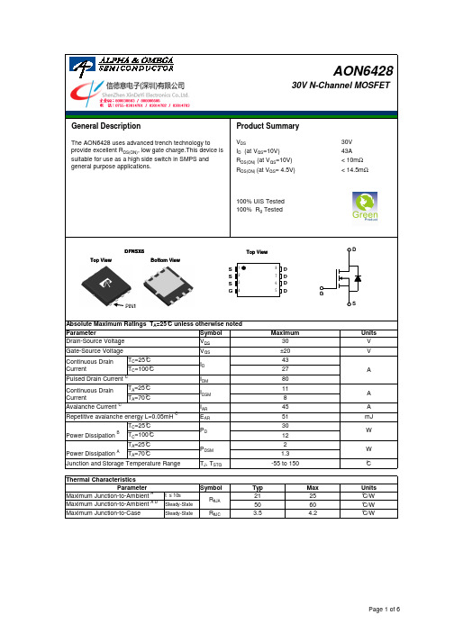
Symbolt ≤ 10s Steady-State Steady-StateR θJCMaximum Junction-to-Case°C/W°C/W Maximum Junction-to-Ambient A D 2.6643.5Power Dissipation B W Power DissipationAW T =70°C T =25°C AT =25°C A T =70°CT =25°C T =100°C Avalanche energy L=0.1mHCmJ Avalanche Current CContinuous Drain CurrentA V MaximumUnits Parameter Absolute Maximum Ratings T A =25°C unless otherwise noted V ±20Gate-Source Voltage Drain-Source Voltage 30Units Maximum Junction-to-Ambient A °C/W R θJA 245330Junction and Storage Temperature Range °CThermal CharacteristicsPulsed Drain Current CContinuous Drain Current GParameterTyp Max T =25°C T =100°C PIN1SymbolMin TypMaxUnits BV DSS 30V V DS =30V, V GS =0V1T J =125°C5I GSS ±100nA V GS(th)Gate Threshold Voltage 1.3 1.92.5V I D(ON)120A 8.710.5T J =125°C13161417m Ωg FS40S V SD 0.721V I S40A C iss 10001300pF C oss 340pF C rss 100pF R g1.32.0ΩQ g (10V)1823nC Q g (4.5V)8.5nC Q gs 3.1nC Q gd 4.8nC t D(on) 5.6ns t r 5.5ns t D(off)18.5ns t f 5ns t rr 2938ns Q rr24nCTHIS PRODUCT HAS BEEN DESIGNED AND QUALIFIED FOR THE CONSUMER MARKET. APPLICATIONS OR USES AS CRITICAL COMPONENTS IN LIFE SUPPORT DEVICES OR SYSTEMS ARE NOT AUTHORIZED. AOS DOES NOT ASSUME ANY LIABILITY ARISING OUT OF SUCH APPLICATIONS OR USES OF ITS PRODUCTS. AOS RESERVES THE RIGHT TO IMPROVE PRODUCT DESIGN,FUNCTIONS AND RELIABILITY WITHOUT NOTICE.Total Gate Charge V GS =10V, V DS =15V, I D =20AGate Drain Charge V GS =0V, V DS =15V, f=1MHz SWITCHING PARAMETERS Total Gate Charge Gate Source Charge Gate resistanceV GS =0V, V DS =0V, f=1MHzTurn-On Rise Time Turn-Off DelayTime V GS =10V, V DS =15V, R L =0.75Ω,R GEN =3ΩTurn-Off Fall TimeTurn-On DelayTime m ΩV GS =4.5V, I D =20AI S =1A,V GS =0VV DS =5V, I D =20A Maximum Body-Diode Continuous CurrentInput Capacitance Output CapacitanceDYNAMIC PARAMETERS R DS(ON)Static Drain-Source On-ResistanceForward Transconductance Diode Forward VoltageV DS =V GS I D =250µA Electrical Characteristics (T J =25°C unless otherwise noted)STATIC PARAMETERS ParameterConditions I DSS Zero Gate Voltage Drain Current µA V DS =0V, V GS = ±20V Gate-Body leakage current Body Diode Reverse Recovery TimeBody Diode Reverse Recovery Charge I F =20A, dI/dt=100A/µsDrain-Source Breakdown Voltage On state drain currentI D =250µA, V GS =0V V GS =10V, V DS =5V V GS =10V, I D =20AReverse Transfer Capacitance I F =20A, dI/dt=100A/µsA: The value of R θJA is measured with the device in a still air environment with T A =25°C.B. The power dissipation P D is based on T J(MAX)=150°C, using junction-to-case thermal resistance, and is more useful in setting the upper dissipation limit for cases where additional heatsink is used.C: Repetitive rating, pulse width limited by junction temperature T J(MAX)=150°C.D. The R θJA is the sum of the thermal impedence from junction to case R θJC and case to ambient.E. The static characteristics in Figures 1 to 6 are obtained using <300 µs pulses, duty cycle 0.5% max.F. These curves are based on the junction-to-case thermal impedence which is measured with the device mounted to a large heatsink,assuming a maximum junction temperature of T J(MAX)=150°C.G. These tests are performed with the device mounted on 1 in 2 FR-4 board with 2oz. Copper, in a still air environment with T A =25°C. The SOA curve provides a single pulse rating.H. Surface mounted on a 1 in 2 FR-4 board with 2oz. Copper.J. Maximum current is limited by bonding wire.TYPICAL ELECTRICAL AND THERMAL CHARACTERISTICSVdsChargeGate Charge Test Circuit & WaveformVdd90%Resistive Switching Test Circuit & WaveformsVddVdsIdVgsBV IUnclamped Inductive Switching (UIS) Test Circuit & WaveformsARDSS2E = 1/2 LI Vdd AR AR。
前言本手册介绍了产品的安装、接线、接口定义和操作说明等相关内容。
本手册版权归深圳市正运动技术有限公司所有,在未经本公司书面授权的情况下,任何人不得翻印、翻译和抄袭本手册中的任何内容。
前述行为均将构成对本公司手册版权之侵犯,本司将依法追究其法律责任。
本手册中的信息资料仅供参考。
由于改进设计和功能等原因,正运动公司保留对本资料的最终解释权!内容如有更改,恕不另行通知!调试机器要注意安全!请务必在机器中设计有效的安全保护装置,并在软件中加入出错处理程序,否则所造成的损失,正运动公司没有义务或责任对此负责。
为了保证产品安全、正常、有效的使用,请您务必在安装、使用产品前仔细阅读本产品手册。
更新记录产品型号:EIO24088总线扩展模块文件名版本号版本(更改)说明更新日期更改人用户手册V1.51.增加端子规格及接线参考2.丰富前言版权说明及安全注意2.修改整体布局,丰富手册内容2023/4/25xcx安全声明●本章对正确使用本产品所需关注的安全注意事项进行说明。
在使用本产品之前,请先阅读使用说明并正确理解安全注意事项的相关信息。
●本产品应在符合设计规格要求的环境下使用,否则可能导致设备损坏,或者人员受伤,因未遵守相关规定引发的功能异常或部件损坏等不在产品质量保证范围之内。
●因未遵守本手册的内容、违规操作产品引发的人身安全事故、财产损失等,我司将不承担任何法律责任。
安全等级定义按等级可分为“危险”、“注意”。
如果没有按要求操作,可能会导致中度伤害、轻伤及设备损伤的情况。
请妥善保管本指南以备需要时阅读,并请务必将本手册交给最终用户。
安装危险◆控制器拆卸时,系统使用的外部供应电源全部断开后再进行操作,否则可能造成设备误操作或损坏设备;◆禁止在以下场合使用:有灰尘、油烟、导电性尘埃、腐蚀性气体、可燃性气体的场所;暴露于高温、结露、风雨的场合;有振动、冲击的场合;电击、火灾、误操作也会导致产品损坏和恶化。
注意◆安装时避免金属屑和电线头掉入硬件电路板内;◆安装后保证其硬件电路板上没有异物;◆安装时,应使其与安装架紧密牢固;◆如果控制器安装不当,可能导致误操作、故障及火灾。
10 CFR 50 • AERB • ASME QME-1* • ASME QSC (NCA-3800) • ASME 第 III 部分 • ASME U核级认证核级认证 • ASN • CNSC CRN-N* HAF 604 • IAEA SC-QA 780 298* • IEEE* • ISO 9001: •E 派克核电门户网站无论您是要建新的发电厂,还是要改进现有电厂,派克都会依照行业统一的质量保证计划,使不同部门的各种产品进入核电市场,提高生产率和利润率。
这些产品包括安全专项和安全相关的核级子系统和组件,以及为非管制工厂区提供的优质的“成熟”商品。
派克门户网站是我们投入数百万美元用于核能研究和发展的承诺之一,是我们承诺提获得越来越多在全球供应且通过认证的核能产品的单一途径。
供行业所要求的高效性、可靠性和成本效益的体现。
我们支持单源购买各种产品系列,通过最新的订购方式提高工厂生产率和利润率。
另外,我们在将近 50 个国家拥有 50,000 名员工,因而门户网站产品在全球都有供应。
有关订购门户网站产品的更多信息,请:拨打电话 256 885 3833(销售)、256 885 3880(技术支持)或 发送电子邮件至 ipdusnuclear@parker .com派克核电门户网站是根据派克现行的 NQA- 1 和 10CFR50 附录 B 规定的质量保证计划开发的,并且采用了行业及规范性文件中规定的最佳实3 级阀门的 ASME N 核级认证外,派克核电门户网站上提供的产品符合 10CFR 第 21 部分中对基本组件的规定,按照认可的质保计划或是商品级物项执行。
专项不会提高质量,而是验证并记录专用项目中已有的的质量。
EU PED*HAF 604*IAEA SC-QA KTA 3507NNSANQA-1Parker Hannifin Ltd.Tachbrook Park DriveTachbrook Park,Warwick, CV34 6TU英国电话:+44 (0) 1926 317 878传真:+44 (0) 1926 317 855********************欧洲、中东和非洲AE – 阿联酋,迪拜电话:+971 4 8127100********************AT – 奥地利,维也纳新城电话:+43 (0)2622 23501-0*************************AT – 东欧,维也纳新城电话:+43 (0)2622 23501 900****************************AZ – 阿塞拜疆,巴库电话:+994 50 2233 458****************************BE/LU – 比利时,尼韦尔电话:+32 (0)67 280 900*************************BY – 白俄罗斯,明斯克电话:+375 17 209 9399*************************CH – 瑞士,埃托瓦电话:+41 (0)21 821 87 00*****************************CZ – 捷克共和国,Klecany电话:+420 284 083 111*******************************DE – 德国,卡尔斯特电话:+49 (0)2131 4016 0*************************DK – 丹麦,巴勒鲁普电话:+45 43 56 04 00*************************ES – 西班牙,马德里电话:+34 902 330 001***********************FI – 芬兰,万塔河电话:+358 (0)20 753 2500parker. ****************FR – 法国,Contamine s/Arve电话:+33 (0)4 50 25 80 25************************GR – 希腊,雅典电话:+30 210 933 6450************************HU – 匈牙利,布达佩斯电话:+36 23 885 470*************************IE – 爱尔兰,都柏林电话:+353 (0)1 466 6370*************************IT – 意大利,Corsico (MI)电话:+39 02 45 19 21***********************KZ – 哈萨克斯坦,阿拉木图电话:+7 7273 561 000****************************NL – 荷兰,奥尔登扎尔电话:+31 (0)541 585 000********************NO – 挪威,阿斯克尔电话:+47 66 75 34 00************************PL – 波兰,华沙电话:+48 (0)22 573 24 00************************PT – 葡萄牙,莱萨·达·帕尔梅拉电话:351 22 999 7360**************************RO – 罗马尼亚,布加勒斯特电话:+40 21 252 1382*************************RU – 俄罗斯,莫斯科电话:+7 495 645-2156************************SE – 瑞典,Spånga电话:+46 (0)8 59 79 50 00************************SK – 斯洛伐克,班斯卡·比斯特里察电话:+421 484 162 252**************************SL – 斯洛文尼亚,新梅斯托电话:+386 7 337 6650**************************TR – 土耳其,伊斯坦布尔电话:+90 216 4997081************************UA – 乌克兰,基辅电话:+380 44 494 2731*************************UK – 英国,沃里克电话:+44 (0)1926 317 878********************ZA – 南非,坎普顿公园电话:+27 (0)11 961 0700*****************************北美地区CA – 加拿大,安大略省米尔顿电话:+1 905 693 3000US – 美国,克利夫兰电话:+1 216 896 3000亚太地区AU – 澳大利亚,城堡山电话:+61 (0)2-9634 7777CN – 中国,上海电话:+86 21 2899 5000HK – 香港电话:+852 2428 8008IN – 印度,孟买电话:+91 22 6513 7081-85JP – 日本,东京电话:+81 (0)3 6408 3901KR – 韩国,首尔电话:+82 2 559 0400MY – 马来西亚,莎阿南电话:+60 3 7849 0800NZ – 新西兰,惠灵顿电话:+64 9 574 1744SG – 新加坡电话:+65 6887 6300TH – 泰国,曼谷电话:+662 186 7000-99TW – 台湾,台北电话:+886 2 2298 8987南美AR – 阿根廷,布宜诺斯艾利斯电话:+54 3327 44 4129BR – 巴西,圣若泽杜斯坎普电话:+55 800 727 5374CL – 智利,圣地亚哥电话:+56 2 623 1216MX – 墨西哥,阿波达卡电话:+52 81 8156 6000核电门户网站手册 M&K 12/10 1M派克授权的本地经销商© 2010 派克汉尼汾公司派克全球办事处联系信息欧洲产品信息中心免费电话:00 800 27 27 5374(AT, BE, CH, CZ, DE, DK, EE, ES, FI, FR, IE,IL, IS, IT, LU, MT, NL, NO, PL, PT, RU, SE,SK, UK, ZA)– 一点的方式。
AND8195/DBoard Mounting Notes for SO8−Flat LeadPrepared by: Steve St. Germain, Phil Celaya, and Isauro Amaro ON SemiconductorINTRODUCTIONVarious ON Semiconductor devices are packaged in an advanced power leadless package named Quad FlatNo−Lead (QFN) Package. The power QFN platform represents the latest in surface mount packaging technology.It is important that the design of the Printed Circuit Board(PCB) and the assembly process follow the suggested guidelines outlined in this document.SO8FL Package OverviewThe SO8FL package was created to allow a larger MOSFET die to fit into a standard SO8IC footprint. This package uses a lead frame design that allows the leads to stick out beyond the molded body size. This feature allows the customer to see the solder fillet during visual inspection. See Figure 1 below.Figure 1. The Underside of an SO8FL Package Figure 2 illustrates how the package height is reduced to a minimum by having both die and wire bond pads on the same plane. When mounted, the leads and the body are directly attached to the board without a space−consuming standoff which is inherent in a leaded package.Figure 2 also illustrates how the ends of the leads go past the edge of the molded package. This configuration allows for the maximum die size within a given footprint, which in turn maximize the board space utilization.Figure 2. Cross−Section of SO8FL PackageIn addition to these features, the SO8FL package has excellent thermal dissipation and reduced electrical parasitic elements due to its efficient and compact design. Printed Circuit Board Design Considerations SMD and NSMD Pad ConfigurationsThere are two different types of PCB pad configurations commonly used for surface mount QFN style packages. These different I/O configurations are:1.Non Solder Masked Defined (NSMD)2.Solder Masked Defined (SMD)As their titles describe, the NSMD contact pads have the solder mask pulled away from the solderable metallization, while the SMD pads have the solder mask over the edge of the metallization, as shown in Figure 3. With the SMD pads, the solder mask restricts the flow of solder paste to the top of the metallization preventing the solder from flowing along the sides of the metal pad. This is different from the NSMD configuration where the solder will flow around both the top and the sides of the metallization.Figure 3. Comparison of NSMD vs. SMD PadsNSMD SMDSolder MaskOpeningSolderablePad OverlayAPPLICATION NOTETypically, the NSMD pads are preferred over the SMD configuration since defining the location and size of the copper pad is easier to control than the solder mask. This is based on the fact that the copper etching process is capable of a tighter tolerance than the solder masking process.In addition, the SMD pads will inherently create a stress concentration point where the solder wets to the pad on top of the lead. This stress concentration point is eliminated when the solder is allowed to flow down the sides of the leads in the NSMD configuration.NSMD Pad ConfigurationsWhen it is dimensionally possible, the solder mask should be located at least "0.076 mm (0.003 in) away from the edge of the solderable pad. This spacing is used to compensate for the registration tolerances of the solder mask, as well as to insure that the solder is not inhibited by the mask as it reflows along the sides of the metal pad.The dimensions of the PCB’s solderable pads should be larger than the device footprint to allow for visual inspection of solder filet. This is shown in Figure 4. The ratio between the package’s pad configuration, and that of the PCB’s, is designed for optimal placement accuracy and reliability.SO8FL Package FootprintSO8FL PCB PatternFigure 4. Printed Circuit Board Layout Using Non−Solder Masked Defined I/O PadsSO8FL Board Mounting ProcessThe surface mount process is optimized by first defining and controlling the following processes:1.Creating and maintaining a solderable metallization on the PCB contacts.2.Choosing the proper solder paste.3.Screening/stenciling the solder paste onto the PCB.4.Placing the package onto the PCB.5.Reflowing the solder paste.6.Final solder joint inspection.Recommendations for each of these processes are located below.PCB Solderable MetallizationThere are two common plated solderable metallization finishes which are used for PCB surface mount devices. In either case, it is imperative that the plating is uniform,conforming, and free of impurities to insure aconsistent solderable system.The first metallization finish consists of an Organic Solderability Preservative (OSP) coating over the copper plated pad. The organic coating assists in reducing oxidation in order to preserve the copper metallization for soldering.The second recommended solderable metallization finish consists of plated electroless nickel over the copper pad, followed by immersion gold. The thickness of the electroless nickel layer is determined by the allowable internal material stresses and the temperature excursions the board will be subjected to throughout its lifetime. Even though the gold metallization is typically a self−limiting process, the thickness should be of at least 0.05 m m thick, and not consist of more than 5% of the overall solder volume. Having excessive gold in the solder joint, can create gold embitterment, which may affect the reliability of the joint. Solder TypeSolder paste such as Cookson Electronics’ P/N WS3060 with a Type 3 or smaller sphere size is recommended. The WS3060 has a water−soluble flux for cleaning. Cookson Electronics’ P/N C0106A can be used if a no−clean flux is preferred.For lead free solders Sn−Ag−Cu, the following alloy (Sn 94.5%, Ag 4.5%, Cu .5%) paste is preferred.Solder Screening onto the PCBStencil screening the solder onto the PCB board is commonly used in the industry. The recommended stencil thickness used is 0.075 mm to 0.127 mm (0.003 in to 0.005 in) and the sidewalls of the stencil openings should be tapered approximately 5° to facilitate the release of the paste when the stencil is removed from the PCB.For a typical edge PCB terminal pad, the stencil opening should be the same size as the PCB mounting pad. However, in cases where the device pad is soldered to the PCB, the stencil opening must be divided into smaller cavities as shown in Figure 5. Dividing the larger pads into smaller screen openings reduces the risk of solder voiding and allows the solder joints for the smaller terminal pads to be at the same height as the larger ones. Typical solder coverage is 60 to 80% of exposed pad area.Package Placement onto the PCBPick and place equipment with the standard tolerance of "0.05 mm or better is recommended. The package will tend to center itself and correct for slight placement errors during the reflow process due to the surface tension of the solder.SO8FL RecommendedStencil PatternFigure 5. Solder stencil design illustrating how stencil openings are divided into an array for large die pads.Solder ReflowOnce the package is placed on the PC board along with the solder paste, a standard surface mount reflow process can be used to mount the part. Figures 6 and 7 are examples of standard reflow profiles for typical Tin/Lead solder and Lead−free solder alloys. Note the S08FL is qualified to meet Pb−free profile requirements per JEDEC Specification J−STD−020C.A recommended profile is available by the manufacturer of the paste since the chemistry and viscosity of the flux matrix will vary. The exact profile will be determined by the Process Engineer based on board density and thickness.These variations will require small changes in the profile in order to achieve an optimized process.TIME (sec)T E M P E R A T U R E (°C )Figure 6. Typical Reflow Profile for StandardTin/Lead SolderTIME (sec)T E M P E R A T U R E (°C )Figure 7. Typical Reflow Profile for StandardPb−Free SolderIn general, the temperature of the part should be raised not more than 25C/sec during the initial stages of the reflow profile. The soak zone then occurs when the part is approximately 1505C and should last for 60 to 180 seconds for Pb−free profiles (30−120 sec for SnPb profiles).Typically, extending the time in the soak zone will reduce the risk of voiding within the solder. The temperature is then raised and will be above the liquidus of the solder for 60 to 150 seconds for Pb−free profiles (30−100 sec for SnPb profiles) depending on the mass of the board. The peak temperature of the profile should be between 245 and 2605C for Pb−free solder alloys (205−2255C for SnPb solders).If required, removal of the residual solder flux can be completed by using the recommended procedures set forth by the flux manufacturer.Final Solder InspectionThe inspection of the solder joints is commonly performed with the use of an X−ray inspection system. With this tool, one can locate defects such as shorts between pads,open contacts, voids within the solder as well as any extraneous solder.In addition to searching for defects, the mounted device should be rotated on its side to inspect the sides of the solder joints with an X−ray inspection system. The solder joints should have enough solder volume with the proper stand−off height so that an “Hour Glass” shaped connection is not formed as shown below in Figure 7. “Hour Glass” solder joints are a reliability concern and must be avoided.Undesirable “Hour Glass’’Solder JointFigure 8. Side view of QFN attachment illustrating preferred and undesirable solder joint shapesRework ProcedureDue to the fact that the SO8FL is a leadless device, the entire package must be removed from the PC board if there is an issue with the solder joints. It is important to minimize the chance of overheating neighboring devices during the removal of the package since the devices are typically in close proximity with each other.Standard SMT rework systems are recommended for this procedure since the airflow and temperature gradients can be carefully controlled. It is also recommended to place the PC board in an oven at 125°C for 4 to 8 hours prior to heating the parts to remove excess moisture from the packages. In order to control the region which will be exposed to reflow temperatures, the board should be heated to 100_C by conduction through the backside of the board in the location of the SO8FL. Typically, heating nozzles are then used, to increase the temperature locally.Once the SO8FL solder joints are heated above their liquidus temperature, the package is quickly removed and the pads on the PC board need to be cleaned. The cleaning of the pads is typically performed with a blade−style conductive tool and with a de−soldering braid. A no−clean flux is used during this process in order to simplify the procedure.Solder paste is then deposited or screened onto the site in preparation of mounting a new device. Due to the close proximity of the neighboring packages in most PC board configurations, a miniature stencil for the individual component is typically required. The same stencil design that was originally used to mount the package can be applied to the mini−stencil for redressing the pad.Due to the small pad configurations of the SO8FL, and since the pads are on the underside of the package, a manual pick and place procedure without the aid of magnification is not recommended. A dual image optical system where the underside of the package can be aligned to the PC board should be used instead.Reflowing the component onto the board can be accomplished by either passing the board through the original reflow profile, or by selectively heating the SO8FL with the same process that was used to remove it. The benefit with subjecting the entire board to a second reflow is that the SO8FL will be mounted consistently and by a profile that is already defined. The disadvantage is that all of the other devices mounted with the same solder type will be reflowed for a second time. If subjecting all of the parts to a second is either a concern or unacceptable for a specific application, than the localized reflow option would be the recommended procedure.ON Semiconductor and are registered trademarks of Semiconductor Components Industries, LLC (SCILLC). SCILLC reserves the right to make changes without further notice to any products herein. SCILLC makes no warranty, representation or guarantee regarding the suitability of its products for any particular purpose, nor does SCILLC assume any liability arising out of the application or use of any product or circuit, and specifically disclaims any and all liability, including without limitation special, consequential or incidental damages.“Typical” parameters which may be provided in SCILLC data sheets and/or specifications can and do vary in different applications and actual performance may vary over time. All operating parameters, including “Typicals” must be validated for each customer application by customer’s technical experts. SCILLC does not convey any license under its patent rights nor the rights of others. SCILLC products are not designed, intended, or authorized for use as components in systems intended for surgical implant into the body, or other applications intended to support or sustain life, or for any other application in which the failure of the SCILLC product could create a situation where personal injury or death may occur. Should Buyer purchase or use SCILLC products for any such unintended or unauthorized application, Buyer shall indemnify and hold SCILLC and its officers, employees, subsidiaries, affiliates, and distributors harmless against all claims, costs, damages, and expenses, and reasonable attorney fees arising out of, directly or indirectly, any claim of personal injury or death associated with such unintended or unauthorized use, even if such claim alleges that SCILLC was negligent regarding the design or manufacture of the part. SCILLC is an Equal Opportunity/Affirmative Action Employer. This literature is subject to all applicable copyright laws and is not for resale in any manner.PUBLICATION ORDERING INFORMATION。
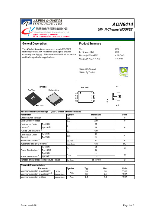
General DescriptionSymbol V DS Parameter Absolute Maximum Ratings T A =25°C unless otherwise notedMaximum Drain-Source Voltage Gate-Source Voltage G SV GSSymbol R θJA R θCSR θJCMaximum Case-to-sinkAMaximum Junction-to-CaseD,F°C/W°C/W 10.51.2T =25°C Continuous Drain Current BMaximum Junction-to-Ambient A,G -55MaximumThermal Characteristics Units °C/W 43ParameterTypical AOI4N60AOD4N60G S DG SDGG D DSS D GD AOU4N60SymbolMinTypMaxUnits600700BV DSS /∆TJ 0.67V/ o C 110I GSS Gate-Body leakage current ±100n ΑV GS(th)Gate Threshold Voltage3.44.1 4.5V R DS(ON) 1.8 2.3Ωg FS 6S V SD 0.761V I S Maximum Body-Diode Continuous Current4A I SM14A C iss 420528640pFC oss 355370pF C rss 2.5 4.87pF R g1.22.53.8ΩQ g 9.51214.5nC Q gs 2.8 3.6 4.5nC Q gd 2.24.4 6.6nC t D(on)17ns µA V Static Drain-Source On-Resistance V GS =10V, I D =2A Reverse Transfer Capacitance V GS =0V, V DS =25V, f=1MHz SWITCHING PARAMETERSI DSS Zero Gate Voltage Drain Current V DS =600V, V GS =0V Gate Drain Charge V DS =5V, I D =250µA V DS =480V, T J =125°C I S =1A,V GS =0VElectrical Characteristics (T J =25°C unless otherwise noted)STATIC PARAMETERS ParameterConditionsZero Gate Voltage Drain Current ID=250µA, VGS=0V BV DSS Maximum Body-Diode Pulsed CurrentInput Capacitance Output CapacitanceDYNAMIC PARAMETERS V Gate resistanceV GS =0V, V DS =0V, f=1MHzTotal Gate Charge V GS =10V, V DS =480V, I D =4ATurn-On DelayTime Gate Source Charge Drain-Source Breakdown Voltage I D =250µA, V GS =0V, T J =25°C I D =250µA, V GS =0V, T J =150°C Diode Forward VoltageV DS =0V, V GS =±30V V DS =40V, I D =2A Forward Transconductance t r 26ns t D(off)34ns t f 21ns t rr 150190230ns Q rr1.92.43µCTHIS PRODUCT HAS BEEN DESIGNED AND QUALIFIED FOR THE CONSUMER MARKET. APPLICATIONS OR USES AS CRITICAL COMPONENTS IN LIFE SUPPORT DEVICES OR SYSTEMS ARE NOT AUTHORIZED. AOS DOES NOT ASSUME ANY LIABILITY ARISING OUT OF SUCH APPLICATIONS OR USES OF ITS PRODUCTS. AOS RESERVES THE RIGHT TO IMPROVE PRODUCT DESIGN,FUNCTIONS AND RELIABILITY WITHOUT NOTICE.Body Diode Reverse Recovery TimeI F =4A,dI/dt=100A/µs,V DS =100VBody Diode Reverse Recovery Charge I F =4A,dI/dt=100A/µs,V DS =100VTurn-On Rise Time Turn-Off DelayTime GS =10V, V DS =300V, I D =4A,R G =25ΩTurn-Off Fall TimeA. The value of R θJA is measured with the device in a still air environment with T A =25°C.B. The power dissipation P D is based on T J(MAX)=150°C in a TO252 package, using junction-to-case thermal resistance, and is more useful in setting the upper dissipation limit for cases where additional heatsinking is used.C. Repetitive rating, pulse width limited by junction temperature T J(MAX)=150°C.D. The R θJA is the sum of the thermal impedance from junction to case R θJC and case to ambient.E. The static characteristics in Figures 1 to 6 are obtained using <300 µs pulses, duty cycle 0.5% max.F. These curves are based on the junction-to-case thermal impedance which is measured with the device mounted to a large heatsink, assuming a maximum junction temperature of T J(MAX)=150°C.G.These tests are performed with the device mounted on 1 in 2 FR-4 board with 2oz. Copper, in a still air environment with T A =25°C.H. L=60mH, I AS =2.8A, V DD =150V, R G =10Ω, Starting T J =25°CTYPICAL ELECTRICAL AND THERMAL CHARACTERISTICSI D (A )Fig 1: On-Region CharacteristicsV R D S (O N )(Ω)I Figure 3: On-Resistance vs. Drain Current and GateN o r m a l i z e d O n -R e s i s t a n c e401.0E-041.0E-031.0E-021.0E-011.0E+001.0E+011.0E+020.20.40.60.8 1.0I S (A )V SD (Volts)Figure 6: Body-Diode Characteristics25°C125°CI D =30A25°125°012345678051015202530V DS (Volts)V GS =5.5V6V10V6.5V 0.1110100246810I D (A )GS (Volts)Figure 2: Transfer Characteristics-55°CV DS =40V25°C125°C1.01.52.02.53.03.54.04.5246810D (A)VoltageV GS =10V00.511.522.53-100-50050100150200Temperature (°C)Figure 4: On-Resistance vs. JunctionTemperature V GS =10V I D =2A0.80.911.11.2-100-5050100150200B V D S S (N o r m a l i z e d )T J (o C)Figure 5: Break Down vs. Junction TemperatureVdsC ha rgeGate Charge Test Circuit & W av eformResistiv e Switching Test Circuit & W av eformsDSS2ARVddVddVdsI dVgsB V I Unclamped Inductive Switching (UIS) Test Circuit & W av eformsI Diode Recovery Vd ARE = 1/2 LI ddVdd AR。