SPD385-40A-MH产品规格书-V3.3
- 格式:pdf
- 大小:1.07 MB
- 文档页数:8
根据IEC 61312 《雷电电磁脉冲的防护》、GB 50057-94 《建筑物防雷设计规范》、GB 50054-95 《低压配电设计规范》、JGJ/T 16-92《民用建筑电气设计规范》及GBJ 64-83《工业与民用电力装置的过电压保护设计规范》中防雷及过电压规范有关防雷分区的划分和各级电源系统雷电及过电压保护要求,针对现场勘察报告中关于配电系统的描述,将其分为三个防雷区分别加以考虑。
由于单级防雷可能会带来因雷电流过大而导致的泄流后残压过大或者保护能力不足引起的设备损坏。
因此选用电源系统多级保护,可防范从直击雷到操作浪涌的各级过电压的侵袭。
1、电源一级防护:设计依据依据GB 50057-94《建筑物防雷设计规范》第六章:防雷击电磁脉冲;第四节,第6.4.1至6412条LPZ0A、LPZ0B区对电涌保护器(SPD)的要求及GB 50054-95《低压配电设计规范》第四章:配电线路的保护中有关低压防雷的有关规定;参照JGJ/T 16-92《民用建筑电气设计规范》第13部分:电力设备防雷、第14 部分接地及安全以及GBJ 64-83《工业与民用电力装置的过电压保护设计规范》第五、六、八章;DL/T620-1997《交流电气装置的过电压保护和绝缘配合》第三章到第十章;DL/T621-1997 《交流电气装置的接地》第三章、第四章、第六章、第七章的部分条文。
设计说明依据《建筑物防雷设计规范》第六章:防雷击电磁脉冲第三节屏蔽、接地和等电位连接的要求:第6.3.4 条及第四节对电涌保护器和其他的要求:第 6.4.7条规定,在LPZOA或LPZ0B区与LPZ1区交界处,从室外引来的线路上安装SPD 当线路有屏蔽时,每个SPD 的雷电流按雷电流的幅值的30%考虑.本建筑物为二类防雷建筑物,首次雷电流幅值为150KA,电源线路为铠装埋地,TN-S配电模式,因此首次直击雷在低压配电线路上每线的分配电流为:在建筑物已安装合格的防直击雷措施后,有50%的雷电流通过引下线流入接地装置,因此每线分配电流为:150KA*50%*30%/4=5.6KA ,按《建筑物防雷设计规范》第六章:第四节:第6.4.7条要求每线标称放电电流不宜小于15KA。
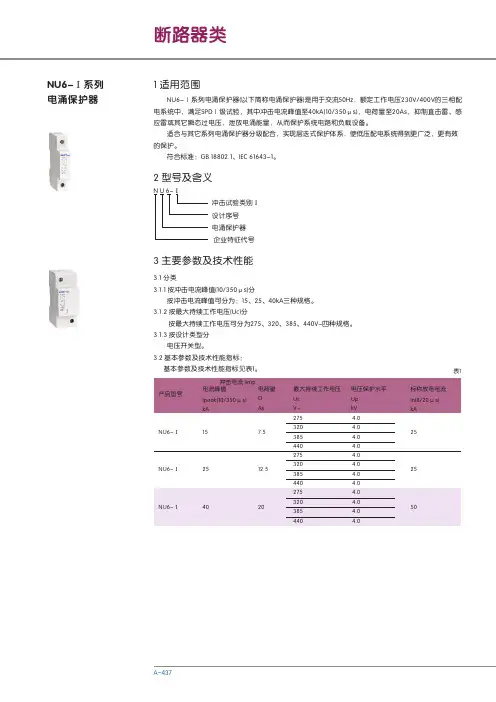
380V SPD4P40KA交流电源避雷器资料电源避雷器三相交流电源避雷器:又称电源避雷模块,电涌保护器/浪涌保护器|浪涌抑制器|避雷器|避雷器是安普迅公司生产的避雷产品,品牌为安迅ANSUNAM系列三相交流电源避雷器应用范围:·三相交流电源避雷器适用于配电室、配电柜、开关柜、交直流配电屏等系统的电源保护;·建筑物内有室外输入的配电箱、建筑物层配电箱;·用于低压(220/380VAC)工业电网和民用电网;·在电力系统中,主要用于自动化机房、变电站主控制室电源屏内三相电源输入或输出端。
三相交流电源避雷器功能与特点·通流容量大,残压低,响应时间快;·漏电流及变化率小;·采用最新热脱离技术,彻底避免火灾;·采用特殊冲击熔片,具有高可靠性;·自带远程告警干接点,便于远程监控;·具有工作故障指示,遥信告警功能;·采用温控保护电路,内置热保护,短路故障自动脱离装置;·3+1保护模式(L-N,N-PE),特别适合电网差的地区使用;·采用标准模块化设计,安装简单,维护方便;·核心元件采用国际知名品牌,性能优异,工作稳定可靠;·可以实现凯文接线;结构严谨,安装方便,维护简单;·工艺考究,能在酸、碱、尘、盐雾及潮湿等恶劣环境下长期工作。
三相交流电源避雷器技术参数:型号AM100A AM80B AM60C AM40D AM40C 标称工作电压Un220V最大持续工作电压Uc320V/385V标称放电电流50kA40kA30kA20kA20kA (In8/20μs)最大放电电流100kA80kA60kA40kA40kA (Imax8/20μs)保护模式L1,L2,L3,N-PE L1,L2,L3,-NN-PEL,N-PEL-NN-PEL,N-PE保护水平Up(8/20μs In)≤2000V≤18001500响应时间≤25ns外形尺寸90*145*6390*145*6390*36*69接线线径25mm225mm216mm210mm2防护等级IP20安装方式35mm导轨安装工作环境环境温度:-40℃~+85℃;相对湿度:≤95%(25℃);海拔≤3km 注:产品规格可能不定期更新,请咨询安普迅公司了解详情。
IEC61643-1-1998:《接至低压电力配电系统的浪涌保护器》通信行业标准通信局(站)低压配电系统用电涌保护器技术要求Performance requirements for Surge Protective Devices Connected to Low-voltageDistribution Systems of Telemunication Stations/SitesYD/T 1235.1-20022002-11-08 发布2002-11-08 实施中华人民XX国信息产业部发布目次前言1 X围2 规X性引用文件3 术语和定义4 使用环境条件4.1 供电条件4.2 气候条件5 分类5.1 按冲击测试电流等级分类5.2 按用途分类5.3 按端口分类5.4 按构成分类6 技术要求6.1 标称额定值6.1.1 优选值6.1.2 SPD分类的冲击测试电流等级规定6.2 整体要求6.2.1 外观质量6.2.2 保护模式6.2.3 分离装置6.2.4 告警功能6.2.5 接线端子连接导线的能力6.3 电涌防护性能6.3.1 最大持续运行电压6.3.2 等级限制电压6.3.3 电压保护水平6.3.4 动作负载试验6.4 安全性能6.4.1 电气间隙和爬电距离6.4.2 外壳防护等级6.4.3 保护接地6.4.4 着火危险性(灼热丝试验)6.4.5 暂时过电压失效安全性6.4.6 暂时过电压耐受特性6.4.7 热稳定性6.5 二端口SPD及带独立输入/输出端子的一端口SPD 的附加要求6.5.1 电压降6.5.2 负载侧电涌耐受能力6.5.3 负载侧短路耐受能力6.6 环境适用性6.6.1 耐振动性能6.6.2 耐高温性能6.6.3 耐低温性能6.6.4 耐湿热性能7 检验规则7.1 交收检验7.2 型式检验8 标志、包装、运输和贮存8.1 标志的内容8.2 包装8.3 运输和贮存8.3.1 运输8.3.2 贮存附录A (规X性附录)通信局(站)配电系统用电涌保护器(SPD)的构形前言制订本标准的目的在于规X我国通信局(站)低压配电系统用电涌保护器的技术要求,并为电涌保护器的设计、生产、检验、选择和应用提供技术依据。
技术标准--配电箱(柜)技术规格书一、总则:本规格书是招标文件的重要组成部分,内容包括设备/材料的规格和技术要求。
投标单位所提供的设备/材料必须符合本规格书的要求。
对投标人所提供设备的要求:设计合理、固定牢固、安装可靠、所用材料具有足够的强度、并且质量合格且无缺陷。
如果投标人所提供的设备具有下述招标人要求之外的装置或功能,须加以注明。
标准设备/材料应按本规格书规定的标准和规范进行设计及加工。
若在设计和加工中应用的某项标准或规范在本规格书中没有规定,则投标单位应详细说明其所采用的标准和规范,并提供该标准或规范的完整中文原件给施工方。
只有当其采用的标准和规际公认的、惯用的,且等于或优于本技术规格书的要求时,此标准或规范才可能为施工方所接受。
本技术规格书中使用的标准如下:GB762《电气设备额定电流》GB1980《电气设备额定频率》IEC-185《电流互感器》IEC-186《电压互感器》GB156《额定电压》GB4025《指示灯和按钮的颜色》GB7251-87《低压开关成套设备》GB4942.2《低压电气外壳防护等级》GB/T13384《机电产品包装通用技术条件》GB14048《低压开关设备和控制设备》2.附件、备件和消耗品投标单位须提供保证设备在质保期内正常运转所必需的附件、备件、工具和消耗品等,在投标书中列出清单,提供名称、用途和制造厂。
3、安装、调试与试运行1)厂家应派有经验的技术人员到现场进行指导安装和调试,直到设备正常运行。
2)厂家应无条件提供全部安装、调试过程中所需的特殊工具,润滑剂和易损件,并配有专用仪器仪表。
3)生产厂家应在现场对设备进行调试和试运行,以检验其设计制作操作性和功能等方面的情况。
4)设备安装完毕,应在施工方工程师的监督下进行试运行前的测试,以证明其可以进行试运行。
试运行应在施工方工程师监督下进行,内容如下:进行设备的所有功能性运行。
运行和检测安全装置。
4、验收当生产厂家所供设备运抵现场后15天内,须由生产厂家、施工单位、监理单位、业主等四方组成的验收小组,对厂家所供设备的外观和数量进行检验和核实。
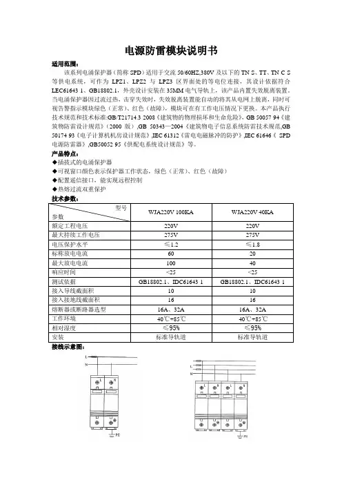
电源防雷模块说明书适用范围:该系列电涌保护器(简称SPD)适用于交流50/60HZ,380V及以下的TN-S、TT、TN-C-S 等供电系统,可作为LPZ1、LPZ2与LPZ3区界面处的等电位连接,其设计依据符合LEC61643-1、GB18802.1,外壳设计安装在35MM电气导轨上,该产品内置失效脱离装置。
当电涌保护器因过流过热,击穿失效时,失效脱离装置能自动的将其从电网上脱离,同时可视告警指示模块绿色(正常)、红色(故障),模块可在有工作电压情况下更换。
本产品执行技术规范和技术标准:GB/T21714.3-2008《建筑物的物理损坏和生命危险》,GB 50057-94《建筑物防雷设计规范》(2000版),GB 50343—2004《建筑物电子信息系统防雷技术规范,GB 50174-93《电子计算机机房设计规范》,IEC 61312《雷电电磁脉冲的防护》,IEC 61646《SPD 电源防雷器》,GB50052-95《供配电系统设计规范》等。
产品特点:◆插拔式的电涌保护器◆可视窗口颜色表示保护器工作状态,绿色(正常)、红色(故障)◆配置遥信接口,能实现远程控制◆热熔过流双重保护技术参数:型号WJA220V-100KA WJA220V-40KA参数额定工程电压220V 220V最大持续工作电压275V 275V电压保护水平≤1.2 ≤1.8标称放电电流60 20最大放电电流100 40响应时间<25 <25测试依据GB18802.1、IDC61643-1 GB18802.1、IDC61643-1接入导线截面积10 10接入接地线截面积16 16熔断器或断路器选型16A、32A 16A、32A工作环境-40℃+85℃-40℃+85℃相对湿度≤95%≤95%安装标准导轨道标准导轨道接线示意图:。
MH413.028SS V1.01.概述本防雷器主要应用于低压供配电系统与用电设备的雷电或其它瞬时过电压的电涌保护。
产品采用“3+1”防护电路,内置过热过流保护功能,可为低压供配电系统与用电设备提供C级防雷(Ⅱ级分类试验)保护。
产品采用一体化底座外形设计,便于安装及维护,并带有遥信告警接口(干接点),便于远端监控。
2.防护和电气性能指标序号项目技术参数1 产品型号 SPD385-40A-MH2 标称工作电压-Un 230V/400VAC3 额定工作频率48~62Hz4 最大持续运行电压-Uc385V(L-N)/255V(N-PE)5 标称放电电流-In(8/20μS)20kA(L-N,N-PE)6 最大放电电流-Imax(8/20μS)40kA(L-N,N-PE)7 电压保护水平-Up(20kA 8/20μS ) ≤1.8kV(L-N)/≤1.0kV(N-PE)8 限制电压-Up(5kA 8/20μS ) ≤1.3kV(L-N)/≤0.8kV(N-PE)9 暂态过电压(TOV)特性-UT385V/5sec (L-N), 400V/5sec (L-PE),10 暂态过电压故障特性(TOV)1430V/200ms(L-PE),1200V/200ms(N-PE)11 耐受短路电流25kArms12 端子接线范围 1.5 mm2~25mm2(柔性)/35mm2(刚性)13 告警端口最大工作电流250V/0.5A(AC)0.1A(DC);125V/1A(AC)0.5(DC)14 外壳阻燃等级UL94 V-015 外壳防护等级 IP2016 产品认证 CE、TUV3.产品结构与造型:z防雷器为一体化底座设计,尺寸为:90mm(L)×70mm(W)×65mm(H),颜色为白色。
z防雷电路采用“3+1”保护电路,简化了TT和TN电源系统中防雷器的选择和安装。
z防雷器的安装固定方式为35mm标准U型导轨安装。
无线测温系列开关柜综合智能操控装置安装使用说明书V1.0版目录一.引用标准 (1)二.产品概述 (1)三. 技术参数 (1)四. 前面板示意图及说明 (4)五.背部端子示意图及说明 (7)六.主要功能 (9)七.安装屏开孔(MM) (21)八.外形尺寸图(MM) (21)九、使用注意事项 (21)十、运输储存 (22)一.引用标准DL/T538-2006《高压带电显示装置技术条件》二.产品概述开关柜无线测温操控装置是一款适用于高中压开关柜的高集成产品。
本装置液晶显示,集一次回路动态模拟图、断路器分合闸状态、手车位置、接地闸刀位置、隔离刀状态、弹簧储能状态、高压带电指示、高压带电闭锁、温湿度显示及控制、照明输出、验电核相等多功能于一体。
产品还具有智能语音防误提示、RS485通讯、人体感应探头、电气节点无线测温等扩展功能。
用户可根据实际需要组合选配。
该装置不仅外型美观大方,且优化了开关柜的整体布局,是新一代开关柜内使用的理想更新换代产品。
三. 技术参数3.1 基本参数3.2 温湿度默认值四. 前面板示意图及说明序号描述序号描述1、5 手车工作位置指示20 按钮“设置”2、6 手车试验位置指示21 按钮“上升”强制加热3 断路器合闸指示22 按钮“下降”强制排风五.背部端子示意图及说明六.主要功能6.1 状态指示功能(具体指示编号见前面板示意图)●手车位置指示1)手车处于工作位置(工作位置触点闭合)时,手车指示红色模拟条(1、5)亮;2)手车处于试验位置(试验位置触点闭合)时,行车指示绿色模拟条(2、6)亮;3)手车处于试验位置和实验位置之间(工作、试验位置触点都未闭合且断路器接点全部未闭合)时,手车指示灯红、绿(1、2、5、6)模拟条都不亮;●断路器状态指示1)断路器合闸(断路器合触点闭合)时,断路器指示红色模拟条(3)亮;2)断路器分闸(断路器分触点闭合)时,断路器指示绿色模拟条(4)亮;3)断路器不在柜内(断路器合、分触点都未闭合)时,断路器指示灯红、绿模拟条(3、4)不亮;●接地开关位置指示1)接地闸刀合闸(接地闸刀分/合触点闭合)时,接地闸刀指示红色模拟条(7)亮;2)接地闸刀未合闸(接地闸刀分/合触点未闭合)时,接地闸刀指示绿色模拟条(8)亮●弹簧储能(储能)触点闭合时,储能指示红灯(9)亮;注意1:以上开关量接入必须为无源接点。
MADE IN TAIWANOPERATING INSTRUCTIONSHH804UDUAL INPUT RTD THERMOMETERINTRODUCTION This instrument is a 4_digit,compact-sized portable digital thermometer designed to use external 100_Platinum RTD as temperature sensor.Tem-perature indication follows Reference Temperature/Resistance Tables (Pt385for European Curve,Alpha=.00385.Pt3926for American Curve,Al pha=.003926. Pt3916 for Japan Curve, Alpha=.003916.)SAFETY INFORMATIONIt is recommended that you read the safety and operation instructions before using the thermometer.WARNINGTo avoid electrical shock, do not use this instrument when working voltagesat the measurement surface over 24V AC or DC.WARNINGTo avoid damage or burns, do not take temperature measurements in micro-wave ovens.ENVIRONMENTALAmbient Operating Ranges:0°C to 50°C (32°F to 122°F) <70% R.H.Storage Temperature:-20°C to 60°C (-4°F to 140°F) <80% R.H.GENERALDisplay:4_ digit liquid crystal display (LCD) with maximum reading of 19999Overload:“----.-“ or “OL” is display.Battery:1.5V x 4 PCS (SIZE AAA) R03P.Battery Life:200 hours typical with carbon zinc battery Auto power off: 30 minutes Dimensions:160mm(H) x83mm(W) x 38mm(D)Weight:Approx. 255g including batteries.SPECIFICATIONSELECTRICALTemperature Scale: Celsius or Fahrenheit user-selectable Measurement Range:Pt385(100_) -200°C to 800°C, (-328°F to 1472°F)Pt3916/Pt3926(100_) -200°C to 630°C, (-328°F to 1166°F)Resolution:0.1°C or 0.2°F Accuracy:Accuracy is specified for operating temperatures over the range of 18°C to 28°C (64°F to 82°F), for 1 year, not including RTD probe error.±(0.05% rdg + 0.2°C) on °C scale ±(0.05% rdg + 0.4°F) on °F scale Temperature Coefficient:0.1 times the applicable accuracy specification per °C from 0°C to 18°C and 28°C to 50°C (32°F to 64°F and 82°F to 122°F).Input Protection:24V dc or 24V ac rms maximum input voltage on any combination of input pins.Maximum Differential Common Mode Voltage (Maximum Voltage be-tween T1 and T2 during measurement): 1volt.Reading Rate: 1sample/second.Input Connector:Accepts 4 pin mini-DIN connectors.OPERATING INSTRUCTIONS1.Power ButtonThebutton turns the thermometer on or off. In the SET mode the unit cannot be powered off. Exit the SET mode to power off.APO function modePress “”power button for more than 6seconds to disable auto power function. The display will show “APO OFF”.2.°C/°F Selecting the Temperature Scale (Main display)Readings are displayed in either degrees Celsius(°C) or degrees Fahren-heit(°F). When the thermometer is turned on, it is set to the temperature scale that was in use when the thermometer was last turned off. To change the temperature scale, press the °C/°F key.3. “ ” Display Back-LightPress the “ ” key to turn on or turn off the back light.4. T1 T2/T1-T2 Main display Input SelectionThe input selection button determines which input is shown on the display;T1,T2or the difference between the two probes (T1-T2).When thermometer is turned on, it is set to T1.5. TYPE(Pt385/Pt3926/Pt3916) Input RTD Probe Select (Main display)The TYPE button selects the RTD curve to use for the input currently shown.When the thermometer is turned on,it is set to the curve that selected when the thermometer was last turned off.6. MIN MAX with Time record Mode (only Main display)Press MIN MAX key to enter the MIN MAX Recording mode,(displays Maximum reading with time,Minimum reading with time and Average reading stored in recording mode).In the this mode the automatic power-off feature is disabledand key,°C/°F key,REL key,SET key,Hi/Lo Li key and main display T1T2T1-T2key,TYPE key are disabled.beeper emits a tone when a new minimum or maximum value is recorded.Push MIN MAX key to cycle through the MAX, MIN and AVG readings.If an overload is recorded,the averaging function is Stopped.In the mode,press HOLD key to stop the recording of readings,all values are zen,press again to restart recording.To prevent accidental loss of MAX and AVG data,in this mode can only be cancelled by pressing hold down the MIN MAX key for 2seconds to exit and erased recorded readings.7. REL Relative mode (only Main display)Press REL key to enter the Relative mode,zero the display,and store displayed Reading as a reference value and annunciator REL is displayed.Press REL key again to exit the relative mode.The relative value can be entered by the user.(See “SET mode”later in this manual.)When the sired Relative value has been entered,press REL key to enter the Relative mode,press SET key use set Relative value as a reference value.Press key again to exit the relative mode.In the Relative mode,the value (can >±1999.9counts)shown on the LCD is always the difference between stored reference and the present reading.8.HOLD Mode (only Main display)Press the HOLD key to enter the Data Hold mode,the “HOLD”annunciator is displayed.When HOLD mode is selected,the thermometer held the sent readings and stops all further measurements.Press the HOLD again to cancel HOLD mode causing thermometer to resume taking ureents.In the MIN/MAX recording mode,press HOLD key to stop the cording.Press HOLD key again to resume recording.(Previously recorded read are not erased).9. SET mode (Relative value set, Time set and Hi/Lo Limits value set)Press SET key to enter Relative values SET mode (Press ENTER key escape relative values set mode),REL set mode.====.=is displayed main display.Relative value is entered via overlay numbers,thenHH804UOMEGAnet ®On-Line ServiceInternet e-mail **************Czech Republic:Frystatska 184, 733 01 Karvina ´, Czech Republic Tel: +420 (0)59 6311899FAX: +420 (0)59 6311114Toll Free: 0800-1-66342e-mail:*****************Germany/Austria:Daimlerstrasse 26, D-75392 Deckenpfronn, Germany Tel: +49 (0)7056 9398-0 FAX: +49 (0)7056 9398-29TollFreeinGermany************e-mail:*************Servicing Europe:U.S.A. and Canada:Sales Service: 1-800-826-6342/1-800-TC-OMEGA Customer Service: 1-800-622-2378/1-800-622-BEST Engineering Service: 1-800-872-9436/1-800-USA-WHEN U.S.A.: ISO 9001 Certified One Omega Drive, Box 4047Stamford, CT 06907-0047Tel: (203) 359-1660FAX: (203) 359-7700e-mail:**************Servicing North America:For immediate technical or application assistance:Mexico:En Espan~ol: (001) 203-359-7803FAX: (001) 203-359-7807e-mail:*******************************.mxUnited Kingdom ISO 9002 Certified One Omega DriveRiver Bend Technology Centre Northbank, Irlam Manchester M44 5BD United KingdomTel: +44 (0)161 777 6611 FAX: +44 (0)161 777 6622Toll Free in United Kingdom: 0800-488-488e-mail:**************.ukCanada:976 BergarLaval (Quebec) H7L 5A1, Canada Tel: (514) 856-6928FAX: (514) 856-6886e-mail:*************Where Do I Find Everything I Need for Process Measurement and Control?OMEGA…Of Course!Shop online at M4501/0607TEMPERATUREⅪߜThermocouple, RTD & ThermistorProbes, Connectors, Panels &Assemblies ⅪߜWire: Thermocouple, RTD &Thermistor ⅪߜCalibrators & Ice Point References ⅪߜRecorders, Controllers & ProcessMonitors ⅪߜInfrared PyrometersPRESSURE, STRAIN AND FORCEⅪߜTransducers & Strain GagesⅪߜLoad Cells & Pressure Gages ⅪߜDisplacement Transducers ⅪߜInstrumentation & AccessoriesFLOW/LEVELⅪߜRotameters, Gas Mass Flowmeters &Flow Computers ⅪߜAir Velocity Indicators ⅪߜTurbine/Paddlewheel Systems ⅪߜTotalizers & Batch ControllerspH/CONDUCTIVITYⅪߜpH Electrodes, Testers & Accessories ⅪߜBenchtop/Laboratory Meters ⅪߜControllers, Calibrators, Simulators &Pumps ⅪߜIndustrial pH & ConductivityEquipmentDATA ACQUISITIONⅪߜData Acquisition & EngineeringSoftware ⅪߜCommunications-Based AcquisitionSystems ⅪߜPlug-in Cards for Apple, IBM &Compatibles ⅪߜDatalogging Systems ⅪߜRecorders, Printers & PlottersHEATERSⅪߜHeating CableⅪߜCartridge & Strip Heaters ⅪߜImmersion & Band Heaters ⅪߜFlexible Heaters ⅪߜLaboratory HeatersENVIRONMENTALMONITORING AND CONTROLⅪߜMetering & Control InstrumentationⅪߜRefractometers ⅪߜPumps & TubingⅪߜAir, Soil & Water Monitors ⅪߜIndustrial Water & Wastewater Treatment ⅪߜpH, Conductivity & Dissolved OxygenInstrumentsRETURN REQUESTS/INQUIRIESDirect all warranty and repair requests/inquiries to the OMEGA Customer Service Department.BEFORE RETURNING ANY PRODUCT(S) TO OMEGA, PURCHASER MUST OBTAIN AN AUTHORIZED RETURN (AR) NUMBER FROM OMEGA’S CUSTOMER SERV ICE DEPARTMENT (IN ORDER TO AV OID PROCESSING DELAYS). The assigned AR number should then be marked on the outside of the return package and on any correspondence.The purchaser is responsible for shipping charges, freight, insurance and proper packaging to prevent breakage in transit.FOR WARRANTY RETURNS, please have the following information available BEFORE contacting OMEGA:1.Purchase Order number under which the product was PURCHASED,2.Model and serial number of the product under warranty, and3.Repair instructions and/or specific problems relative to the product.FOR NON-WARRANTY REPAIRS,consult OMEGA for current repair charges. Have the following information available BEFORE contacting OMEGA:1. Purchase Order number to cover the COST of the repair,2.Model and serial number of the product, and3.Repair instructions and/or specific problems relative to the product.WARRANTY/DISCLAIMEROMEGA ENGINEERING, INC. warrants this unit to be free of defects in materials and workmanship for a period of 13 months from date of purchase. OMEGA’s WARRANTY adds an additional one (1) month grace period to the normal one (1) year product warranty to cover handling and shipping time. This ensures that OMEGA’s customers receive maximum coverage on each product.If the unit malfunctions, it must be returned to the factory for evaluation. OMEGA’s Customer Service Department will issue an Authorized Return (AR) number immediately upon phone or written request. Upon examination by OMEGA, if the unit is found to be defective, it will be repaired or replaced at no charge. OMEGA’s WARRANTY does not apply to defects resulting from any action of the purchaser, including but not limited to mishandling,improper interfacing, operation outside of design limits, improper repair, or unauthorized modification. This WARRANTY is VOID if the unit shows evidence of having been tampered with or shows evidence of having been damaged as a result of excessive corrosion; or current, heat, moisture or vibration; improper specification; misapplication; misuse or other operating conditions outside of OMEGA’s control. Components in which wear is not warranted, include but are not limited to contact points, fuses, and triacs.OMEGA is pleased to offer suggestions on the use of its various products.However, OMEGA neither assumes responsibility for any omissions or errors nor assumes liability for any damages that result from the use of its products in accordance with information provided by OMEGA, either verbal or written.OMEGA warrants only that the parts manufactured by the company will be as specified and free of defects. OMEGA MAKES NO OTHER W ARRANTIES OR REPRESENTATIONS OF ANY KIND W HATSOEVER, EXPRESSED OR IMPLIED,EXCEPT THAT OF TITLE, AND ALL IMPLIED W ARRANTIES INCLUDING ANY WARRANTY OF MERCHANTABILITY AND FITNESS FOR A PARTICULAR PURPOSE ARE HEREBY DISCLAIMED. LIMITATION OF LIABILITY: The remedies of purchaser set forth herein are exclusive, and the total liability of OMEGA with respect to this order, whether based on contract, warranty, negligence, indemnification, strict liability or otherwise, shall not exceed the purchase price of the component upon which liability is based. In no event shall OMEGA be liable for consequential,incidental or special damages.CONDITIONS: Equipment sold by OMEGA is not intended to be used, nor shall it be used: (1)as a “Basic Component” under 10 CFR 21 (NRC), used in or with any nuclear installation or activity; or (2) in medical applications or used on humans. Should any Product(s) be used in or with any nuclear installation or activity, medical application, used on humans, or misused in any way, OMEGA assumes no responsibility as set forth in our basic WARRANTY /DISCLAIMER language, and, additionally, purchaser will indemnify OMEGA and hold OMEGA harmless from any liability or damage whatsoever arising out of the use of the Product(s) in such a manner.he policy of OMEGA Engineering, Inc. to comply with all worldwide safety and EMC/EMI ations that apply. OMEGA is constantly pursuing certification of its products to thepean New Approach Directives. OMEGA will add the CE mark to every appropriate device certification.nformation contained in this document is believed to be correct, but OMEGA accepts no ty for any errors it contains, and reserves the right to alter specifications without notice.NING: These products are not designed for use in, and should not be used for, human cations.OMEGAʼs policy is to make running changes, not model changes, whenever an improvement is possible. This affords our customers the latest in technology and engineering.OMEGA is a registered trademark of OMEGA ENGINEERING, INC.© Copyright 2007 OMEGA ENGINEERING, INC. All rights reserved. This document may not be copied, photocopied, reproduced, translated, or reduced to any electronic medium or machine-readable form, in whole or in part, without the prior written consent of OMEGA ENGINEERING, INC.overlay ENTER key, stored the relative value, enter Time set mode.Time set mode,(Press ENTER key can escape Time set mode)=.===:==is displayed in second and third display.Time (hours,minutes,seconds)value is entered via overlay numbers,then press overlay ENTER key.Time start from set time value, enter Hi/Lo Limits value set mode.Hi Limit value set mode,(Press ENTER key can escape Hi Limit value set mode),====.=is displayed in main display,Hi Limit value is entered via overlay numbers,then press overlay ENTER key,stored the Hi Limit value,enter Lo Limit value set mode (Press ENTER key can escape Lo Limit value set mode).====.=is displayed in main display,Lo Limit value is entered via overlay numbers,then press overlay ENTER key,stored the Lo Limit value and exit SET mode.When the thermometer is turned on.The Relative set value and Hi/Lo Limits set value that was in use when thermometer was last turned off set values.T1/T2 T1-T2 second display Input Selectionhe input selection button determines which input is shown on the second splay;T1,T2or the difference between the two probes (T1-T2).When the ermometer is turned on, it is set to T2.TYPE(Pt385/Pt3926/Pt3916) Input RTD Probe select (second display)he TYPE button selects the RTD curve to use for the input currently own.When the thermometer is turned on,it is set to the curve that was lected when the thermometer was last turned off.Hi/Lo Limits mode (only Main display)ess the Hi/Lo Limits button to enter the Hi/Lo Limits comparative mode,hen the input temperature exceeds the Hi or Lo Limits value,the beeper mits a continuous pulse tone.Press the Hi/Lo Limits button again to exit e Hi/Lo Limits mode.TD PROBE CONNECTIONMPERATURE VS RESISTANCE TABLE(ITS90)°C Pt385Pt3926Pt3916-200°C 18.521_16.996_17.057_-100°C 60.256_59.479_59.565_0°C 100.000_100.000_100.000_100°C 138.505_139.272_139.171_200°C 175.856_177.362_177.155_300°C 212.052_214.275_213.957_400°C 247.092_250.018_249.584_500°C 280.977_284.591_284.036_600°C 313.708_317.994_317.313_700°C 345.280_--800°C 375.700_--OPERATOR MAINTENANCEWARNINGTo avoid possible electrical shock, disconnect the thermocouple connectorsfrom the thermometer before removing the cover.Battery Replacement1. Power is supplied by 4pcs 1.5V (SIZE AAA) R03P.2. The “” appears on the LCD display when replacement is needed. Toreplace battery remove screw from back of meter and lift off the battery cover.3. Remove the battery from battery contacts and replace.4. When not in use for long periods the batteries should be removed.5. Do not store in locations with high temperatures, or high humidity.CleaningPeriodically wipe the case with a damp cloth and detergent, do not use abra sives or solvents.V1. 040307。