ft61f143规格书
- 格式:docx
- 大小:16.50 KB
- 文档页数:2
ft61f143规格书《FT61F143规格书》是一份产品规格书,用于描述该产品的技术参数、功能特性、性能指标等相关信息。
下面将以简体中文的形式,详细介绍该规格书的内容。
产品概述:FT61F143是一款多功能、高性能的电子产品。
它具有出色的性能表现和广泛的应用领域。
下面将详细介绍其技术参数和功能特性。
1.技术参数1.1外观尺寸:该产品采用紧凑型设计,外形尺寸为100mm x 100mm x 50mm,方便携带和安装。
1.2重量:产品重量约为500克,具有良好的轻便性和便携性。
1.3工作温度:工作温度范围为-20℃至60℃,能够适应各种环境下的工作需求。
1.4储存温度:储存温度范围为-40℃至70℃,便于长期储存和运输。
1.5输入电压:产品的输入电压范围为100V至240V,能够适应全球不同的电压标准。
1.6电池容量:产品内置的可充电电池容量为5000mAh,提供长时间的使用时间。
2.功能特性2.1高清显示:FT61F143产品配备了一块10英寸的高清显示屏,显示效果清晰,色彩鲜艳。
2.2多功能输入输出接口:产品具备多种输入输出接口,包括USB 接口、HDMI接口、耳机接口等,方便用户连接各种外部设备。
2.3多媒体播放:产品支持多种音视频格式的播放,用户可以轻松观看电影、听音乐等多种媒体娱乐。
2.4 Wi-Fi功能:产品内置Wi-Fi模块,支持无线网络连接,用户可以随时随地进行网络浏览和在线娱乐。
2.5蓝牙连接:产品支持蓝牙连接功能,可以与其他蓝牙设备进行无线传输和共享文件。
2.6内置摄像头:产品内置前置摄像头和后置摄像头,支持拍照和视频通话功能。
2.7多任务处理:产品搭载了强大的处理器和内存配置,能够同时运行多个应用程序,满足用户多任务处理的需求。
3.性能指标3.1处理器:产品采用Quad-core 1.5GHz处理器,处理速度快,运行稳定。
3.2内存:产品内置4GB的运行内存,可以存储大量的数据和应用程序。
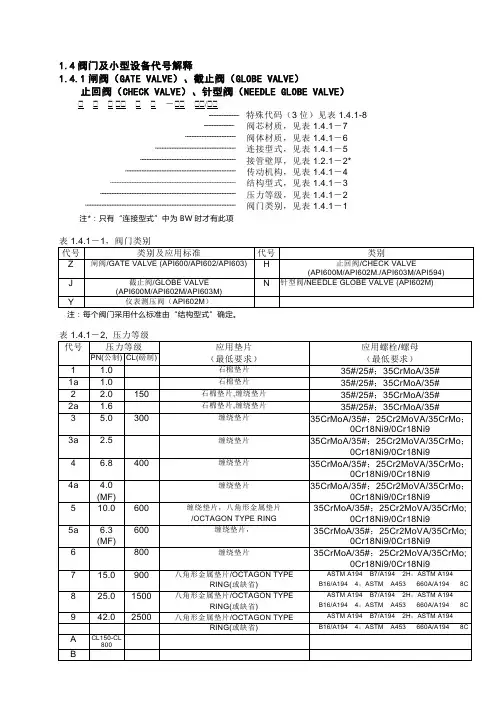
1.4阀门及小型设备代号解释1.4.1闸阀(GATE VALVE)、截止阀(GLOBE VALVE)止回阀(CHECK VALVE)、针型阀(NEEDLE GLOBE VALVE) - / 特殊代码(3位)见表1.4.1-8阀芯材质,见表1.4.1-7阀体材质,见表1.4.1-6连接型式,见表1.4.1-5接管壁厚,见表1.2.1-2*传动机构,见表1.4.1-4结构型式,见表1.4.1-3压力等级,见表1.4.1-2阀门类别,见表1.4.1-1 注*:只有“连接型式”中为BW时才有此项注:每个阀门采用什么标准由“结构型式”确定。
注: 每个阀门选用何种材料的垫片和螺栓、螺母由“阀体材料”确定。
对CL900.1500.2500三个等级的阀门,一般采用压力密封阀盖,此时“阀盖垫片”和“阀盖螺栓”项缺省。
等级1a、2a、3a、4a、5a适用于JB标准阀门。
注: 如果阀门的结构型式为“2”、“8”和“9”,即阀盖为压力密封阀盖,则该表中的“阀盖垫片材料”和“阀盖螺栓材料”栏缺省。
如果阀门的结构型式为“5”,则该表中的“阀杆填料”栏缺省。
表1.4.1-8,特殊代码1.4.2球阀(BALL VALVE)特殊代码(3位)见表1.4.1-8阀芯材质,见表1.4.2-2阀体材质,见表1.4.1-6连接型式,见表1.4.1-5接管壁厚,见表1.2.1-2*传动机构,见表1.4.1-4结构型式,见表1.4.2-1压力等级,见表1.4.1-2阀门类别:球阀/BALL VALVE,代号-Q1.4.3 旋塞阀(PLUG VALVE)阀芯材质,见表1.4.3-2阀体材质,见表1.4.1-6连接型式,见表1.4.1-5接管壁厚,见表1.2.1-2*传动机构,见表1.4.1-4结构型式,见表1.4.3-1压力等级,见表1.4.1-2阀门类别:旋塞阀/PLUG VALVE,代号-P1.4.4 蝶阀(BUTTERFLY VALVE)阀芯材质,见表1.4.4-2阀体材质,见表1.4.1-6连接型式,见表1.4.1-5接管壁厚,见表1.2.1-2*传动机构,见表1.4.1-4结构型式,见表1.4.4-1压力等级,见表1.4.1-2阀门类别:蝶阀/BUTTERFLY VALVE,代号-D1.4.5 疏水阀(STEAM TRAP VALVE)阀芯材质,见表1.4.5-2阀体材质,见表1.4.1-6连接型式,见表1.4.1-5结构型式,见表1.4.5-1压力等级,见表1.4.1-2阀门类别:疏水阀/STEAM TRAP VALVE,代号-S1.4.6 过滤器(STRAINER)阀体材质,见表1.2.1-3连接型式,见表1.4.1-5接管壁厚,见表1.2.1-2*结构型式,见表1.4.6-1压力等级,见表1.3.1-2阀门类别:过滤器(STRAINER),代号-T阀芯材质一般为304。
技密AA (工场) GVF-III规格表参数说明第 1 页共 24 页阅 读 说 明GVF-III电梯EVECD微机所用的规格表参数ROM地址的范围为40018-411EC,其中40018-40517为定时器设定区,40720-40899为IO变量设定区;RAM地址为118008—1191DC,其中118008—118507为定时器设定区,118710—1188ef为IO变量设定区。
@1.参数说明中代号说明:“k**”表示其对应数据寄存器的数据是以十进制方式表示,具体数值根据不 同的设定而不同。
“H**”表示其对应数据寄存器的数据是以十六进制方式表示,具体数值根据 不同的设定而不同。
“有功能”是指电梯具有某特定功能时数据寄存器的设定值。
“无功能”是指电梯不设定某特定功能时数据寄存器的设定值。
“------”是指设定数据寄存器参数时不需要考虑电梯是否具有某特定功能。
2.备注说明:“已取消”表示该变量在程序中未使用,该变量在程序中无意义。
“未使用”表示该变量在程序中有使用,但是其功能未体现,属可扩展功能用。
3.计算公式中符号说明:I为曳引比。
D为绳轮直径(mm)。
R为减速比。
N为旋转编码器脉冲数。
4.本规格表说明用于指引GVF-III梯B1000101、B1000102版程序,GVF-III梯其它版本程序仅作参考用。
spechd(0) 40000 ------ ------H0 和数计算开始地址,H40000 spechd(1) 40001 ------ ------H4 和数计算开始地址,H40000 spechd(2) 40002 ------ ------H0 和数计算开始地址,H40000 spechd(3) 40003 ------ ------H0 和数计算开始地址,H40000 spechd(4) 40004 ------ ------H0 和数计算开始地址,H40000 spechd(5) 40005 ------ ------H0 和数计算开始地址,H40000spechd(6) 40006 ------ ------H** 和数计算字节数,规格表和数计算长度,在规格表增加或者减少变量时才会发生变化,具体的长度可从程序的BIN文件中$30006中获取。

疏水阀说明书相关统计数字显示,一些地区、行业投资增长过快。
一季度,城镇固定资产投资同比增长29.8%,分地区看,全国投资增幅超过35%的省份有16个;分产业看,第二产业比重继续增加,第三产业比重有所下降;分行业看,制造业30个行业中,投资增幅超过40%的有16个。
在投资加快的同时,部分行业产能过剩的压力继续加大。
从钢铁行业看,虽然产量上升,但一季度钢铁行业销售收入同比仅增长6.3%,利润下降57.1%,亏损企业亏损额同比上升1.3倍。
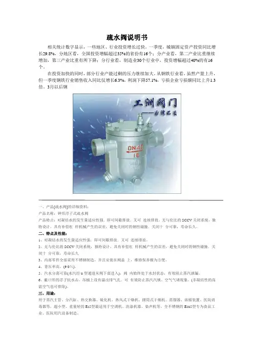
3月以后钢一、产品[疏水阀]的详细资料:产品名称:钟形浮子式疏水阀产品特点:对凝结水的发生量适应性强.即可间歇排放.叉可连续排放。
无与伦比的SCCV关闭系统,独特设计,具有补偿杠杆机械产生的误差,避免关闭时的钢性碰撞.关闭十分可靠,寿命长久。
二、特点及性能:1、对凝结水的发生量适应性强.即可间歇排放.叉可连续排放。
2、无与伦比的SCCV关闭系统,独特设计,具有补偿杠杆机械产生的误差,避免关闭时的钢性碰撞.关闭十分可靠,寿命长久3、内部零件全部采用不锈钢制造,并且安装在阀盖上,维修保养极为方便。
4、背压率高。
(9 0%)。
5、汽水分离可靠(水汽经u型通道从阀下部进入),阀内始终处于水封状态,有效阻止蒸汽泄漏。
6、敝口形的浮子抗水击。
吊桶上设有溢出排气孔.可有效防止蒸汽汽锁、空气气堵现象。
(非凝结性的高温空气也可排除)。
三、用途:用于蒸汽主管、分汽缸、热交换器、硫化机、热风式干燥机、圆筒式干燥机、蒸馏器、浓缩装置、医院消毒器等。
超小型、重量轻的Es5型最适用于空调机、洗涤机器、染声机等。
全不锈钢的Esu5型专为食品工业、医院用汽设备制造。
四、耐磨损的SCCV关闭方式:SCCV姜.闭系统是自动定心,自动关闭系统(SelfClosing and Cente ring Valve System)的英文缩写.下同。
该关闭方式突破了传统的设计,巧妙地利用凝结水土流出时的吸力和阀内的压力使阀芯关闭。

Industrial Control Panels - ComponentSee General Information for Industrial Control Panels - ComponentSTEGO ELEKTROTECHNIK GMBH E234324 Kolpingstrasse 2174523 Schwaebisch Hall, GERMANYAir heaters, for mounting in industrial control panels, Model(s) CR 0305 or 1305 followed by 1 to 4 or 9, followed by 0, 9 or 2 followed by 00 up to 40Air heaters, for mounting in industrial control panels, Model(s) CS and CSF 0320x.y zz*Air heaters, for mounting in industrial control panels, Model(s) DCR Series, followed by x30(where x30 may be 030 or 130), followed by 9, followed by Z(where Z maybe 2, 3, 4, 5, 6, 7, 8), followed by .Y(where Y may be 1, 2, 3), followed by -XX (where XX may be 00, 01, 02, 03, 04, 05, 06, 07, 08, 09, 10, 11, 12, 13, 14, 15, 16, 17, 20.) Air heaters, for mounting in industrial control panels, Model(s) HGL 04640.1-00, HGL 04640.2-00, HGL 04641.2-00Air heaters, for mounting in industrial control panels, Model(s) Series HVI 030 followed by 7 or 8 followed by 0, 1, 2, 3, 4, 5, 6, or 7 followed by 0, 1, 2 or 9 followed by 00 up to 40Fan kits, "SJ 019", Model(s) 01925.0 and 01925.1 followed by 00 or 01Fan kits, Model(s) LE 019, followed by 30, 31, 32, 33, 40, 41, 42, 43 or 50, 51, 52, 53, followed by 0 or 1, followed by 00 or 01.Filter fan hoods, "FFH086", Model(s) FFH08670.0-00, FFH08671.0-00, FFH08672.0-00, FFH08673.0-00,FFH08674.0-00, FFH08680.0-00, FFH08681.0-00, FFH08682.0-00, FFH08683.0-00 and FFH08684.0-00Filter fan kits, Model(s) FF 018/EF 118, followed by 00, 01, 02, 03, 04, 05 or 21, followed by 0 or 1, followed by 00, 01, 02, 03Filter fan kits, Filter Kits, "FPI 018/118", Model(s) FPI followed by 018 or 118, followed by 7, followed by 0, 1, 2, 3 or 4, followed by .0, 1, 2, 3 or 9, followed by -0 thru 4, followed by 0 thru 1.Filter fan kits, Filter Kits, "FPO 018", Model(s) FPO followed by 018 or 118, followed by 8, followed by 0,1,2,3 or 4,followed by .0,1,2,3 or 9,followed by -0 thru 4,followed by 0 thru 1Fluorescent surface mounted luminaires, Model(s) SL 0252 followed by 4, 5 or 7, followed by 0 or 1, followed by 00 to 07 incl., 10 to 12 incl., 16 or 17.Industrial Control Panel - Heaters, Model(s) 031 with a prefix HV or HVL, followed by 00, 01, 02, 03, 10, 11, 12, 13, 14, 15, followed by .0 or .9, may be followed by a -00, -01, -02, -03, -04, -05, -06, -11, 12, -14.LED Lights, Model(s) LED followed by 021 or 022, followed by 0, 1, 2, followed by 0, followed by .0, followed by -00 through -99LED Lights, Model(s) LED followed by 025, followed by 4, followed by 0, 1 or 2, followed by .0, .1 or .3, followed by -0 or -1, followed by 0 through 9.LED Lights, Model(s) LED followed by 121 or 122, followed by 0, 1, 2, 3, followed by 4, followed by .0, followed by -00 through -99Open Type, Air Heaters, Model(s) 03021.9(@), 03022.9(@), 03024.9(@), 03028.9(@), 03029.9(@), 03031.9(@), 03033.9(@), 04640.9-XX(+), 04641.0-XX(+), 04641.9-XX(+)Open Type, Air Heaters, Model(s) 140 followed by 00, 01, 03, 05, 06, 07, 08, followed by .0 or .9, followed by additional suffix digitsOpen Type, Air Heaters, Model(s) CS 028, followed by 0, followed by 0 or 1 or 2, followed by 1 or 2 or 9, followed by 0-20.Open Type, Air Heaters, Model(s) CS 030(&)Open Type, Air Heaters, Model(s) CS 128, followed by 0, followed by 0 or 1 or 2, followed by 1 or 2 or 9, followed by 0-20.Open Type, Air Heaters, Model(s) CS 130(&)Open Type, Air Heaters, Model(s) CSF 028, followed by 1 or 2, followed by 0 or 1 or 2 or 3, followed 9, followed by 0-60.Open Type, Air Heaters, Model(s) CSL 028, followed by 1, followed by 0 or 1, followed by 9, followed by 0-20. Open Type, Air Heaters with blower, Model(s) 043ZZ.X-00(#), 046ZZ.X-00(#), HGL 04640.0-XX(+)Open Type, Component Heaters (PTC), Model(s) RC016(%), RCE016(%%)Pressure compensators, Model(s) 28405.0-00, 28406.0-00(#) - where "ZZ" may be 00, 01, 03, 04, 09, 16, 24, 28 or 32 and X may be 0 or 9(%%) - followed by 22, 23, 24 and 25, followed by .0 followed by additional suffix digits.(%) - followed by 02, 09, and 10(&) - followed by 6, followed by 0, followed by 0 or 9 (0 = 230 V ac, 9 = 120 V ac), followed by 00 or 01. (+) - "XX" maybe 00, 01, 02, 03 or 05(@) - Model numbers may be followed by additional suffix digits indicating minor variations, such as color* - where "x" may be 0, 1, 2, 3 or 9; y may be 0 or 9 and "zz" may be 00 to 30.Marking: Company name, model designation, and the Recognized Component Mark, .Last Updated on 2019-11-07STEGO ELEKTROTECHNIK GMBHKolpingstrasse 21Schwaebisch Hall, 74523 GermanyThe appearance of a company's name or product in this database does not in itself assure that products so identified have been manufactured under UL's Follow-Up Service. Only those products bearing the UL Mark should be considered to be Certified and covered under UL's Follow-Up Service. Always look for the Mark on the product.UL permits the reproduction of the material contained in the Online Certification Directory subject to the following conditions: 1. The Guide Information, Assemblies, Constructions, Designs, Systems, and/or Certifications (files) must be presented in their entirety and in a non-misleading manner, without any manipulation of the data (or drawings). 2. The statement "Reprinted from the Online Certifications Directory with permission from UL" must appear adjacent to the extracted material. In addition, the reprinted material must include a copyright notice in the following format: "© 2020 UL LLC"Industrial Control Panels Certified for Canada - ComponentSee General Information for Industrial Control Panels Certified for Canada - ComponentSTEGO ELEKTROTECHNIK GMBH E234324 Kolpingstrasse 2174523 Schwaebisch Hall, GERMANYAir heaters, for mounting in industrial control panels, Model(s) CR 0305 or 1305 followed by 1 to 4 or 9, followed by 0, 9 or 2 followed by 00 up to 40Air heaters, for mounting in industrial control panels, Model(s) CS and CSF 0320x.y zz*Air heaters, for mounting in industrial control panels, Model(s) DCR Series, followed by x30(where x30 may be 030 or 130), followed by 9, followed by Z(where Z maybe 2, 3, 4, 5, 6, 7, 8), followed by .Y(where Y may be 1, 2, 3), followed by -XX (where XX may be 00, 01, 02, 03, 04, 05, 06, 07, 08, 09, 10, 11, 12, 13, 14, 15, 16, 17, 20.) Air heaters, for mounting in industrial control panels, Model(s) HGL 04640.1-00, HGL 04640.2-00, HGL 04641.2-00Air heaters, for mounting in industrial control panels, Model(s) Series HVI 030 followed by 7 or 8 followed by 0, 1, 2, 3, 4, 5, 6, or 7 followed by 0, 1, 2 or 9 followed by 00 up to 40Fan kits, "SJ 019", Model(s) 01925.0 and 01925.1 followed by 00 or 01Fan kits, Model(s) LE 019, followed by 30, 31, 32, 33, 40, 41, 42, 43 or 50, 51, 52, 53, followed by 0 or 1, followed by 00 or 01.Filter fan hoods, "FFH086", Model(s) FFH08670.0-00, FFH08671.0-00, FFH08672.0-00, FFH08673.0-00,FFH08674.0-00, FFH08680.0-00, FFH08681.0-00, FFH08682.0-00, FFH08683.0-00 and FFH08684.0-00Filter fan kits, Model(s) FF 018/EF 118, followed by 00, 01, 02, 03, 04, 05 or 21, followed by 0 or 1, followed by 00, 01, 02, 03Filter fan kits, Filter Kits, "FPI 018/118", Model(s) FPI followed by 018 or 118, followed by 7, followed by 0, 1, 2, 3 or 4, followed by .0, 1, 2, 3 or 9, followed by -0 thru 4, followed by 0 thru 1.Filter fan kits, Filter Kits, "FPO 018", Model(s) FPO followed by 018 or 118, followed by 8, followed by 0,1,2,3 or 4,followed by .0,1,2,3 or 9,followed by -0 thru 4,followed by 0 thru 1Fluorescent surface mounted luminaires, Model(s) SL 0252 followed by 4, 5 or 7, followed by 0 or 1, followed by 00 to 07 incl., 10 to 12 incl., 16 or 17.Industrial Control Panel - Heaters, Model(s) 031 with a prefix HV or HVL, followed by 00, 01, 02, 03, 10, 11, 12, 13, 14, 15, followed by .0 or .9, may be followed by a -00, -01, -02, -03, -04, -05, -06, -11, 12, -14.LED Lights, Model(s) LED followed by 021 or 022, followed by 0, 1, 2, followed by 0, followed by .0, followed by -00 through -99LED Lights, Model(s) LED followed by 025, followed by 4, followed by 0, 1 or 2, followed by .0, .1 or .3, followed by -0 or -1, followed by 0 through 9.LED Lights, Model(s) LED followed by 121 or 122, followed by 0, 1, 2, 3, followed by 4, followed by .0, followed by -00 through -99Open Type, Air Heaters, Model(s) 03021.9(@), 03022.9(@), 03024.9(@), 03028.9(@), 03029.9(@), 03031.9(@), 03033.9(@), 04640.9-XX(+), 04641.0-XX(+), 04641.9-XX(+)Open Type, Air Heaters, Model(s) 140 followed by 00, 01, 03, 05, 06, 07, 08, followed by .0 or .9, followed by additional suffix digitsOpen Type, Air Heaters, Model(s) CS 028, followed by 0, followed by 0 or 1 or 2, followed by 1 or 2 or 9, followed by 0-20.Open Type, Air Heaters, Model(s) CS 030(&)Open Type, Air Heaters, Model(s) CS 128, followed by 0, followed by 0 or 1 or 2, followed by 1 or 2 or 9, followed by 0-20.Open Type, Air Heaters, Model(s) CS 130(&)Open Type, Air Heaters, Model(s) CSF 028, followed by 1 or 2, followed by 0 or 1 or 2 or 3, followed 9, followed by 0-60.Open Type, Air Heaters, Model(s) CSL 028, followed by 1, followed by 0 or 1, followed by 9, followed by 0-20. Open Type, Air Heaters with blower, Model(s) 043ZZ.X-00(#), 046ZZ.X-00(#), HGL 04640.0-XX(+)Open Type, Component Heaters (PTC), Model(s) RC016(%), RCE016(%%)Pressure compensators, Model(s) 28405.0-00, 28406.0-00(#) - where "ZZ" may be 00, 01, 03, 04, 09, 16, 24, 28 or 32 and X may be 0 or 9(%%) - followed by 22, 23, 24 and 25, followed by .0 followed by additional suffix digits.(%) - followed by 02, 09, and 10(&) - followed by 6, followed by 0, followed by 0 or 9 (0 = 230 V ac, 9 = 120 V ac), followed by 00 or 01. (+) - "XX" maybe 00, 01, 02, 03 or 05(@) - Model numbers may be followed by additional suffix digits indicating minor variations, such as color* - where "x" may be 0, 1, 2, 3 or 9; y may be 0 or 9 and "zz" may be 00 to 30.Marking: Company name, model designation and the Recognized Component Mark for Canada, .Last Updated on 2019-11-07STEGO ELEKTROTECHNIK GMBHKolpingstrasse 21Schwaebisch Hall, 74523 GermanyThe appearance of a company's name or product in this database does not in itself assure that products so identified have been manufactured under UL's Follow-Up Service. Only those products bearing the UL Mark should be considered to be Certified and covered under UL's Follow-Up Service. Always look for the Mark on the product.UL permits the reproduction of the material contained in the Online Certification Directory subject to the following conditions: 1. The Guide Information, Assemblies, Constructions, Designs, Systems, and/or Certifications (files) must be presented in their entirety and in a non-misleading manner, without any manipulation of the data (or drawings). 2. The statement "Reprinted from the Online Certifications Directory with permission from UL" must appear adjacent to the extracted material. In addition, the reprinted material must include a copyright notice in the following format: "© 2020 UL LLC"。
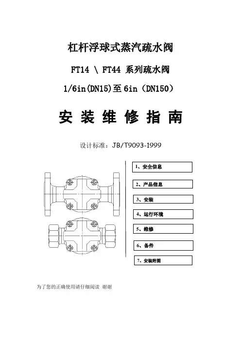
杠杆浮球式蒸汽疏水阀FT14 \ FT44 系列疏水阀1/6in(DN15)至6in(DN150)安装维修指南设计标准:JB/T9093-1999为了您的正确使用请仔细阅读谢谢1、安全信息.2、产品信息3、安装4、运行环境5、维修6、备件7、安装附图1.安全信息遵守运行说明,由专业合格人员正确安装、调试、维护是该阀门安全运行的唯一保证。
(参见附安全信息第11部分)安装中必须遵守管道线路和工厂建筑安装指南的安装指南,工具的正确使用方法及配备必要的安全设备。
警告:阀门中阀体垫片、密封垫片包括所有薄的支撑环、不锈钢垫片,如果其操作处理不当将导致对人划伤、割伤!隔离:考虑到正在关闭或者已经关闭的阀前的截止阀,可能使管路系统或者其他部分、操作人员处于危险之中,都要进行隔离操作。
危险可能包括通风隔离保护设备、报警装置,确保截止阀逐步关闭,以免系统管路震动。
压力:在进行维修之前,请考虑管道中的物质。
确保对维修的该阀门与压力系统安全隔离,并确保被隔离部分的压力完全排出,不要认为压力表显示为零时,就确定已经无压力,需要打开泄压阀来完全泄压,再进行操作。
温度:对要进行维修的阀门隔离后要冷却至常温,以免烫伤,并且要考虑到穿防护服、防护镜和安全帽。
处理:这些产品可再循环利用。
处理得当不会对生态造成危害。
2、产品信息2.1、简介FT14、FT44浮球式蒸汽疏水阀结构为内置自动排空气装置。
可供型号有FT14、FT44(R-L)(流向从右到左);FT14、FT44(R-L)(流向从左到右);FT14、FT44(V)(流向从上到下),FT14、FT44-C增加一个可手动调节针阀作为破蒸汽气锁装置,以上三种流向型号均可配置这样的装置机构。
2.2、口径和连接口径:从1/2in--6in(DN15-DN150)螺纹连接:GB/T7505(55°) GB/T12716(60°) BSP(英制) NPT(美制)法兰连接:GB/T国标 JB/T机械部 HG化工部 ASME美标 JIS日标压力范围:0.25Mpa--10.0Mpa(2.5bar-100bar) 125Lb--900Lb 10K--20KFT14(R-L)螺纹连接 FT14-C(R-L)螺纹连接1in-6in(DN25-DN150)主阀主件FT44(R-L)法兰连接 FT44-C(R-L)法兰连接2.3、限制条件(执行标准:ISO 6552)项目GB/T、 JB/T、 HG国标、机械部、化工部单位:MpaASME美标单位:LbJIS日标单位:K阀体最大设计压力 1.6 2.5 4.0 6.3 150 300 5 10 PMA 最大允许压力 1.6 2.5 4.0 6.3 150 300 5 10 TMA 最大允许温度:°C 250 250 250 250 250 250 250 250 PMO 最大操作压力 1.4 2.2 3.2 5.0 125 250 3.5 8 TMO 最大操作温度:°C 250 250 250 250 250 250 250 250 冷态测试最大水压 2.4 3.75 6.0 9.5 230 450 8 152.4、运行范围3.安装注:在进行安装操作前仔细阅读第1节的《安全信息》参照安装维修指南、铭牌和技术手册,确定产品符合安装的条件3.1、检查材料、压力和温度的最大值。
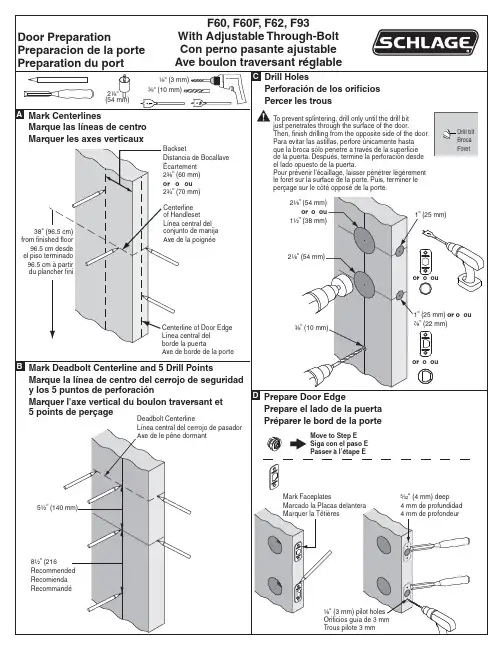
2¹⁄₈” (54 mm)or o ou 1¹⁄₂” (38 mm)2¹⁄₈” (54 mm)1” (25 mm)F60, F60F, F62, F93With Adjustable Through-Bolt Con perno pasante ajustable Ave boulon traversant réglableBacksetDistancia de Bocallave Écartement 2³⁄₈” (60 mm)or o ou 2³⁄₄” (70 mm)Centerline of Handleset Línea central del conjunto de manija Axe de la poignée38" (96.5 cm)from finished floor 96.5 cm desde el piso terminado 96.5 cm à partir du plancher fini5¹⁄₂” (140 mm)8¹⁄₂” (216 Recommended Recomienda RecommandéCenterline of Door Edge Línea central del borde la puertaAxe de borde de la porteMark Deadbolt Centerline and 5 Drill PointsMarque la línea de centro del cerrojo de seguridad y los 5 puntos de perforaciónMarquer l'axe vertical du boulon traversant et5 points de perçageDeadbolt Centerline Línea central del cerrojo de pasador Axe de le pêne dormantDrill HolesPerforación de los orificios Percer les trousDoor PreparationPreparacion de la porte Preparation du portA B C To prevent splintering, drill only until the drill bit just penetrates through the surface of the door.Then, finish drilling from the opposite side of the door.Para evitar las astillas, perfore únicamente hasta que la broca sólo penetre a través de la superficie de la puerta. Después, termine la perforación desde el lado opuesto de la puerta.Pour prévenir l'écaillage, laisser pénétrer légèrement le foret sur la surface de la porte. Puis, terminer le perçage sur le côté opposé de la porte.Drill bit Broca Foret¹⁄₈" (3 mm) pilot holes Orificios guía de 3 mm Trous pilote 3 mmMark CenterlinesMarque las líneas de centro Marquer les axes verticaux2¹⁄₈"(54 mm)¹⁄₈"(3 mm)³⁄₈"(10 mm)³⁄₈” (10 mm)Move to Step E Siga con el paso E Passer à l’étape E⁵⁄₃₂" (4 mm) deep 4 mm de profundidad 4 mm de profondeurPrepare Door EdgePrepare el lado de la puerta Préparer le bord de la porteMark FaceplatesMarcado la Placas delantera Marquer la Têtières D or o ou1” (25 mm) or o ou ⁷⁄₈” (22 mm)or o ouDoor Jamb PreparationPreparación de la jamba de la puerta Préparation du montant de la porteDrill 3 Holes for StrikesPerforación 3 de los orificios para las placas hembraPercer 3 les trous pour la gâche1" (25 mm)⁵⁄₁₆" (8 mm) deep⁵⁄₁₆"(8 mm)⁵⁄₁₆"(8 mm)Two (2) ⁷⁄₈" (22 mm) holes,1¹⁄₈" (29 mm) deepDos (2) agujeros de 22 mm y 29 mm de profundidad Deux (2) trous 22 mm,29 mm de profondeurDistance from Handleset to DeadboltDistancia del conjunto de la manija al cerrojo de pasador Distance de la poignée au pêne dormantMortise for StrikesEscopleado para placas hembra Mortaiser la gâche¹⁄₈" (3 mm) pilot holes Orificios guía de 3 mm Trous pilote 3 mmF60/F62 Only Solamente UniquementEFF60, F60F, F62, F93With Adjustable Through-Bolt Con perno pasante ajustable Ave boulon traversant réglableMark FaceplatesMarcado la Placas delantera Marquer la Têtières³⁄₁₆" (4 mm) deep 4 mm de profundidad 4 mm de profondeur(888) 805-9837© Allegion 2014Printed in U.S.A.F-Series Door Prep Rev. 11/14-online。
F2X14-D使用说明书产品版本密级V2.0.0产品名称:F2X14-D共30页F2X14-D使用说明书此说明书适用于下列型号产品:型号产品类别F2114-D GPRS电力级嵌入式IP MODEMF2414-D WCDMA电力级嵌入式IP MODEMF2614-D EVDO电力级嵌入式IP MODEMF2814-D FDD LTE电力级嵌入式IP MODEM厦门四信通信科技有限公司Add:厦门市集美区软件园三期诚毅大街370号A06栋11层客户热线:400-8838-199电话:+86-592-6300320传真:+86-592-5912735网址文档修订记录日期版本说明作者2015.5.26初始版本ZBQ/YJH 2016.4.1V1.0.1增加F2414-D和F2614-D ZBQ/ZQZ 2016.5.10V1.0.2修改产品外观图、供电电压范围FaineFaine 2017.9.23V2.0.0更新地址增加4G著作权声明本文档所载的所有材料或内容受版权法的保护,所有版权由厦门四信通信科技有限公司拥有,但注明引用其他方的内容除外。
未经四信公司书面许可,任何人不得将本文档上的任何内容以任何方式进行复制、经销、翻印、连接、传送等任何商业目的的使用,但对于非商业目的的、个人使用的下载或打印(条件是不得修改,且须保留该材料中的版权说明或其他所有权的说明)除外。
商标声明Four-Faith 、四信、、、均系厦门四信通信科技有限公司注册商标,未经事先书面许可,任何人不得以任何方式使用四信名称及四信的商标、标记。
产品外形图注:不同型号配件和接口可能存在差异,具体以实物为准。
目录第一章产品简介 (7)1.1产品概述 (7)1.2产品特点 (7)1.3产品规格 (8)第二章安装 (11)2.1概述 (11)2.2开箱 (11)2.3安装与电缆连接 (11)2.4电源说明 (13)2.5指示灯说明 (13)第三章参数设置 (15)3.1界面说明 (15)3.2配置选项说明 (17)3.2.1“本地串口设置”项: (17)3.2.2“本地串口2设置”项: (17)3.2.3“DTU工作模式设置”项: (17)3.2.4“GPRS拨号参数设置”项: (18)3.2.5“支撑平台相关设置”项: (18)3.2.6“企业网关相关设置”项: (18)3.2.7“多IP数据中心”项: (18)3.2.8“多连接策略”项: (18)3.2.9“其他配置”项: (19)3.2.10“网管平台相关设置”项: (19)3.2.11“管理员登录设置”项: (19)3.2.12“ICMP参数设置”项: (19)3.2.13“自定义UDP帧格式”项: (19)3.3读写配置 (20)3.4修改配置 (21)第四章使用说明 (22)4.1工作模式使用说明 (22)4.1.1DC模式 (22)4.1.2透传模式 (22)4.2连接方式使用说明 (22)4.2.1长连接方式 (22)4.2.2短连接方式 (23)4.3查看系统及连接状态 (23)4.4远程升级的使用说明 (24)4.5本地串口升级 (24)第五章测试 (26)5.1DC测试 (26)5.1.1DCUDP模式 (26)5.1.2DCTCP模式测试 (29)附录一常见问题 (30)第一章产品简介1.1产品概述F2X14-D电力级嵌入式IP Modem是一种物联网无线数据终端,利用GPRS/WCDMA/EVDO/LTE网络为用户提供无线数据传输功能。
V X : t o u c h - m c uFT61F08数据手册主要特性8−bit基于EEPROM的RISC MCU Program: 8k x 14; RAM: 1k x 8; Data: 256 x 824 / 28 / 32引脚高精度12−bit ADC 4个定时器, 7路独立PWM − 3路带死区控制SPI, I2C, USART低Standby, WDT和工作电流POR, LVR, LVD – 单输入比较器可配置源电流和灌电流高ESD, 高EFT低V DD工作电压HIRC可微调8−bit CPU (EEPROM)•49条RISC指令: 1T、2T or 4T •16 MHz / 1T(V DD ≥ 2.7)•多达32个引脚Memory•PROGRAM: 8k x 14 bit (读/写保护)•DATA: 256 x 8 bit•RAM: 1k x 8 bit•16层硬件堆栈•扇区加密, 支持IAP工作条件(5V, 25°C)•V DD (V POR ≤ 1.9V)V POR − 5.5 V (通过POR自动调整,0°C以上≤1.7V)•工作温度等级1−40 − +125 °C •工作温度等级2−40 − +105 °C •工作温度等级3−40 − + 85 °C •低Standby 0.2 μA•WDT 2.9 μA•正常模式(16 MHz / 1T) 276 μA/mips 高可靠性•100万次擦写次数(typical)•> 20年/ 85°C存储(typical)•ESD > 8 kV, EFT > 5.5 kVADC (12−bit)•12−bit 精度(≤ 1 MHz ADC时钟)•8 + 1 通道•V ADC−REF✓内部:0.5, 2.0, 3.0, V DD✓外部:+, − 可选•自动阈值比较•触发方式:手动, 自动可选•支持延时触发和自动校准PWM (Total 7路)•支持在SLEEP下运行•7个捕捉/比较/PWM通道:✓独立:占空比,极性•3个通道(多达6个I/O):✓互补输出+死区•前沿消隐,自动故障刹车(I/O, LVD, ADC)•沿对齐,中心对齐,单脉冲模式Timers•WDT (16−bit):3−bit预分频•Timer1 (16−bit): 16−bit预分频•Timer2 (16−bit): 4−bit预分频•Timer4 (8−bit):3−bit预分频•自动重载•支持在SLEEP下运行•LIRC, 1 or 2x {指令时钟, HIRC, 晶振, EC}通信接口•SPI, I2C, USARTI/O PORTS (多达30个I/O)•上拉/下拉电阻•开漏•30个I/O源电流: 2, 4, 14 or 26mA (5V, 25°C) •30个I/O漏电流: 53 or 62 mA(5V, 25°C)•30个I/O:中断/唤醒电源管理•SLEEP•LVR:2.0, 2.2, 2.5, 2.8, 3.1, 3.6, 4.1(V)•LVD:2.0, 2.4, 2.8, 3.0, 3.6, 4.0 (V) (LVD可用作极性可选的单输入比较器功能)系统时钟(SysClk)•HIRC高速内部振荡器✓16MHz <±0.5% typical (2.5−5.5V,25°C)✓可微调✓1, 2, 4, 8, 16, 32, 64, 128分频•LIRC低功耗低速内部振荡器✓32 kHz或256kHz•EC外部时钟(I/O输入)•LP / XT晶振输入✓双速时钟启动(HIRC或LIRC)✓故障保护时钟监控其他特性(欢迎垂询)•½ V DD LCD偏置集成开发环境(IDE)•片上调试(OCD),ISP•3个硬件断点•软复位,暂停,单步,运行等封装•SOP24 SSOP24 TSSOP24 SOP28 SSOP28 LQFP32产品信息和选型表此处a= R; RoHS b = B; Tube= G; Green= T; T&RMCU产品订购信息目录1.结构框图和引脚 (10)1.1.引脚图 (11)1.2.管脚描述---按功能分类 (13)2.GPIO (17)2.1.IO端口相关寄存器汇总 (20)2.2.I/O配置 (25)2.3.PORTx功能及优先级 (27)2.4.PORT端口变化中断 (28)2.5.关于读端口PORTx (28)3.上电复位 (31)3.1.上电复位流程 (31)3.2.复位时序 (31)3.3.上电复位延时 (32)4.系统复位 (33)4.1.系统复位相关寄存器汇总 (34)4.2.低电压复位 (34)4.3.非法指令复位 (35)4.4.软件复位 (35)4.5.EMC复位 (35)4.6.上电配置过程(BOOT) (35)4.7.复位源标志位 (36)5.LVD低电压侦测 (37)5.1.LVD相关寄存器汇总 (37)5.2.检测外部电压 (37)5.3.LVD中断 (38)6.振荡器和系统时钟 (39)6.1.振荡器模块相关寄存器汇总 (40)6.2.时钟源模式 (42)6.3.外部时钟模式 (42)6.3.1.振荡器起振定时器(OST) (42)6.3.2.EC模式 (42)6.3.3.LP和XT模式 (42)6.3.4.内部时钟模式 (43)6.3.5.频率选择位(MCKCF) (43)6.3.6.HIRC和LIRC时钟切换时序 (43)6.3.7.HIRC时钟特殊功能 (44)6.4.时钟切换 (45)6.4.1.系统时钟选择(SCS) 位 (45)6.4.2.振荡器起振超时状态(OSTS) 位 (45)6.4.3.双速时钟启动模式 (45)6.4.4.双速启动模式配置 (46)6.4.5.双速启动顺序 (46)6.4.6.故障保护时钟监控器 (46)6.4.7.故障保护检测 (47)6.4.8.故障保护操作 (47)6.4.9.故障保护条件清除 (47)6.4.10.复位或从休眠中唤醒 (47)6.5.外设时钟门控 (48)6.6.时钟输出 (49)7.慢时钟测量 (50)7.1.慢时钟测量相关寄存器汇总 (50)7.2.测量原理 (51)7.3.上电自动测量 (51)7.4.操作步骤 (53)8.看门狗定时器 (54)8.1.看门狗时钟源 (54)8.2.WDT相关寄存器汇总 (55)9.高级定时器TIM1 (56)9.1.特性 (56)9.3.功能描述 (70)9.3.1.计数基本单元 (70)9.3.2.计数控制器 (79)9.3.3.捕捉比较通道 (84)9.3.4.TIM1中断 (96)9.3.5.故障刹车源 (97)9.3.6.前沿消隐 (99)10.通用定时器TIM2 (100)10.1.特性 (100)10.2.Timer2相关寄存器汇总 (101)10.3.功能描述 (108)10.3.1.计数基本单元 (108)10.3.2.捕捉比较通道 (109)10.3.3.TIM2中断 (111)11.基本定时器TIM4 (112)11.1.特性 (112)11.2.TIM4相关寄存器汇总 (112)11.3.TIM4时钟源 (114)11.4.预分频器 (114)11.5.TIM4中断 (114)12.睡眠模式 (115)12.1.进入SLEEP (115)12.2.睡眠的唤醒 (116)12.2.1.使用中断唤醒 (117)12.3.睡眠的系统时钟 (117)13.中断 (118)13.1.中断相关寄存器汇总 (119)13.2.外部中断管脚选择 (127)13.3.中断的使能 (127)13.5.睡眠下的中断 (127)13.6.现场保护 (128)14.数据EEPROM和PROM (129)14.1.DATA EEPROM相关寄存器汇总 (129)14.2.EEADRL和EEADRH寄存器 (131)14.2.1.EECON1和EECON2寄存器 (131)14.3.使用数据EEPROM (131)14.3.1.读数据EEPROM存储器 (132)14.3.2.写数据EEPROM存储器 (132)14.3.3.自动擦除功能 (132)14.3.4.防止误写操作的保护措施 (133)14.3.5.关于GIE的清0 (133)14.4.闪存程序存储器概述 (134)14.4.1.读闪存程序存储器 (135)14.4.2.擦除闪存程序存储器 (136)14.4.3.写闪存程序存储器 (137)14.5.修改闪存程序存储器 (138)14.6.配置字UCFGx/FCFGx读访问 (139)14.7.写校验 (139)14.8.PROM内容保护 (139)15.12bit ADC模块 (140)15.1.ADC相关寄存器汇总 (141)15.2.ADC的配置 (144)15.2.1.校准ADC (145)15.2.2.端口配置 (145)15.2.3.通道选择 (145)15.2.4.触发方式选择 (145)15.2.5.触发源选择 (145)15.2.6.触发类型选择 (145)15.2.7.触发延时配置 (145)15.2.8.ADC参考电压 (146)15.2.9.转换时钟 (146)15.2.10.中断 (147)15.2.11.转换结果的格式 (147)15.2.12.阈值比较 (148)15.3.ADC的工作原理 (148)15.3.1.启动自动校准 (148)15.3.2.启动转换 (149)15.3.3.转换完成 (149)15.3.4.终止转换 (149)15.3.5.休眠模式下ADC的工作 (149)15.3.6.外部触发器 (150)15.3.7.A/D转换步骤 (150)15.4.A/D采集时间要求 (152)16.SPI接口 (154)16.1.SPI相关寄存器汇总 (156)16.2.SPI配置 (160)16.2.1.通信时钟SCK设置 (160)16.2.2.数据处理流程 (161)16.2.3.硬件CRC校验 (162)16.2.4.从机模式的睡眠唤醒 (163)17.I2C接口 (164)17.1.I2C接口相关寄存器汇总 (165)17.2.I2C配置 (171)17.2.1.主机发送 (172)17.2.2.主机接收 (173)17.2.3.从机发送 (174)17.2.4.从机接收 (175)17.2.5.广播呼叫(General Call) (175)ART接口 (176)ART接口相关寄存器汇总 (177)18.2.功能描述 (182)18.2.1.一般描述 (182)18.2.2.异步工作模式 (182)18.2.3.同步工作模式 (183)18.2.4.半双工模式 (184)18.2.5.红外工作模式 (184)18.2.6.智能卡模式 (185)18.2.7.LIN Master模式 (185)18.2.8.多芯片通信模式 (186)18.2.9.自动波特率检测 (187)19.存储区读/写保护 (188)20.程序存储器 (189)将程序存储器当作数据存储器读取 (189)21.特殊功能寄存器(SPECIAL FUNCTION REGISTERS, SFR) (191)21.1.初始化配置寄存器 (191)21.2.用户寄存器 (193)21.3.堆栈 (208)21.4.STATUS寄存器 (210)21.5.间接寻址 (211)21.5.1.传统数据存储器 (211)21.5.2.线性数据存储器 (212)21.5.3.闪存程序存储器 (212)22.指令集汇总(INSTRUCTION SET) (214)22.1.读-修改-写(RMW) 指令 (216)22.1.指令详细描述 (217)23.芯片的电气特性 (227)23.1.极限参数 (227)23.2.工作特性 (227)23.3.POR, LVR, LVD (228)23.4.I/O 端口电路 (229)23.5.工作电流(I DD) (229)23.6.内部振荡器 (230)23.7.ADC(12bit)和ADC VREF (231)23.8.Program和Data EEPROM (232)23.9.EMC特性 (232)23.10.特性图 (233)24.芯片封装信息 (239)附录1,寄存器类型 (245)附录2,文档更改历史 (246)1. 结构框图和引脚图1-1系统结构框图标准缩写列表如下:1.1. 引脚图]1H C _2M I T [/N 3H C _1M I T /K C S _I P S /0B 1H C _1M I T /I S O M _I P S /0A 2H C _1M I T /O S I M _I P S /1A ]X R _T R A S U [/]L C S _C 2I [/K L C P S I /2A R T E _C D A /2H C _2M I T /5N A /4A XT _T R A S U /4N A /6A 0D V L E /X R _T R A S U /3N A /7A N 1H C _1M I T /B R L C M /1D V L E /2N A /0C 2D V L E /]O S I M _I P S [/1C S O /1N A /1C 3D V L E /]I S O M _I P S [/2C S O /0N A /7B ]A D S _C 2I [/]X T _T R A S U [/T A D P S I /N F E R V /6B DD B P /7N A /4H C _1M I T /O K L C D P /]3H C _1M I T [/]K C S _I P S [ D P /]2H C _1M I T [D P /]1H C _1M I T [/]K C _T R A S U [C P /]N 2H C _1M I T [C P /]N 3H C _1M I T [C P /R TE _1M I T B P /L C S _C 2I /]R T E _C D A [B P /A D S _C 2I /N I K B _1M I T B P /3H C _1M I T B P /PF E R V /3H C _2M I T /S S N _I P S N G图 1-2 SOP24 / SSOP24 / TSSOP24 1]N 2H C _1M I T [/6C ]S S N _I P S [/0D ]K C _T R A S U [/]1H C _1M I T [/1D ]K C S _I P S [/]3H C _1M I T [/3D O K L C /4H C _1M I T /7N A /1B ]1H C _2M I T [/N 3H C _1M I T /K C S _I P S /0B DN 1H C _1M I T /I S O M _I P S /0A 2H C _1M I T /O S I M _I P S /1A DD ]A D S _C 2I [/]X T _T R A S U [/T A D P S I /N FE R V /6B ]X R _T R A S U [/]L C S _C 2I [/K L C P S I /2A ]O K L C [/]N I K B _1M I T [/4D N 2H C _1M I T /6N A /3A C P /]N 3H C _1M I T [C P /R T E _1M I T B P /L C S _C 2I /]R T E _C D A [B P /A D S _C 2I /N I K B _1M I T C P B P /3H C _1M I T B P /0N A /2C S O /]I S O M _I P S [/3D V L E C P /1N A /1C S O /]O S I M _I P S [/2D V L E C P /2N A /1D V L E /B R L C M /N 1H C _1M I T D P /]4H C _1M I T [A P /3N A /X R _T R A S U /0D V L E A P /4N A /X T _T R A S U A P /K C _T R A S U /1H C _2M I T A P /5N A /2H C _2M I T /R T E _C D A图 1-3 SOP28 (B)]2H C _1M I T [/2D ]K C S _I P S [/]3H C _1M I T [/3D O K L C /4H C _1M I T /7N A /1B 1H C _1M I T /I S O M _I P S /0A DN D D N I K B _1M I T /A D S _C 2I /3B ]N 2H C _1M I T [/6C ]N 3H C _1M I T [/5C R T E _1M I T /4C 3C 3H C _1M I T /4B ]AD S _C 2I [/]X T _T R A S U [/T A D P S I /N FE R V /6B ]X R _T R A S U [/]L C S _C 2I [/K C P S I /2A D P /]1H C _1M I T [/]K C _T R A S U [D P /]S S N _I P S [C P /]N 1H C _1M I T [B P /P F E R V /3H C _2M I T /S S N _I P S B P /0N A /2C S O /]I S O M _I P S [/3D V L E C P /1N A /1C S O /]O S I M _I P S [/2D V L E N G C P /2N A /1D V L E /B R L C M /N 1H C _1M I T A P /3N A /X R _T R A S U /0D V L E A P /4N A /X T _T R A S U A P /K C _T R A S U /1H C _2M I T A P /5N A /2H C _2M I T /R T E _C D A A P /6N A /N 2H C _1M I T D P /]N I K B _1M I T [/]O K L C [图 1-4 SSOP28 (C)1SOP24 / SSOP24 / TSSOP24脚位中,PC7内部接地,使用时请勿配置为输出高或上拉。
UNDERCOUNTER DISHWASHER MODELS:KDTE104EBL4(Black)KDTE104EWH4(White)KDTE104ESS4(Stainless)KDTE104EBS4(Black Stainless)Illus.No.Part No.Description1Literature PartsW10806906InstallationInstructionsW10921032Energy GuideW10751710Use&Care GuideW10904612Tech Sheet2Arm,Hinge8534854Left Hand8534853Right Hand3W10844384Barrier,Vapor4W10073520Insulation,Door Illus.No.Part No.Description5Access PanelW10526114BlackW10526115White6Panel,Front(Includes11,14&16)W10872620BlackW10872621WhiteW10872619StainlessW10872623Black Stainless7W10687133Set Screw8W10518815Insulation,Four LayerIllus.No.Part No.Description9Handle AssemblyW10786161Stainless10W10195726Stud,Mounting11W10854504Light Pipe12FastenerW10503548BlackW10503549White13304392Screw14W10692757Barrel Nut,Front Panel153400071Screw16NameplateW10518672GreyIllus.No.Part No.Description1Console Assembly(Includes Insert)W10905443BlackW10905444White2W10711884Screw(Short)Illus.No.Part No.Description3W10825638Box,Connector4W10348408Screw(Long)5W10653840Latch Assembly(Includes Switch)6W10902006Control,ElectronicIllus.No.Part No.Description7W10825369Brace,Connector8W10792164Jumper,4wireIllus.No.Part No.Description1W10348409Screw28281217Screw3W10712597Inner Door Illus.No.Part No.Description4W10667473Seal,Door Bottom5W10901996Wiring HarnessIllus.No.Part No.Description6W10620296Dispenser Assembly7W10771404Seal,Console/DoorIllus.No.Part No.Description1W10195037Lever,Overfill Switch2W10769066Hose3W10195536Inlet,Water(Also Order Item4)48531323Gasket5W10213825Nut,Water Inlet(Also Order Item4) 6371505Clamp,Hose Illus.No.Part No.Description7W10327250Fill Valve Assembly83390631Screw9W10734532Switch,Overfill Control10W10647205Housing,Overfill(Also Order Item11)118531743Gasket,Flat12W10195038Nut,StandpipeIllus.No.Part No.Description13W10195036Float&RetainerAssembly14W10786175Miscellaneous PartsBag(Contains2Screws,2Clamps,&2Brackets)15370445Clamp,Hose16W10545278Drain Loop with CheckValve AsemblyTUB AND FRAME PARTSTUB AND FRAME PARTSIllus.No.Part No.Description1W10681492Tub Assembly(Includes HeaterAssembly)2W10713315Assembly,TerminalBox3W10300924Gasket,Tub4W10813122Plug,Tub5W10544004Strike,Latch6304392Screw7W10835073Seal,Cabinet8W10681564Support Assembly,Rear9W10084086Door BalanceAssembly103367670Screw118269145Bracket,Undercounter Illus.No.Part No.Description123400074Screw13W10337661Strain Relief14W10348411Screw15W10190778Wheel Leg16W10619352Leveler,Leg173378128Washer,Pronged Cup188270020Spring,Door Balance193400014Screw,Grounding20W10653292Cover,Terminal Box21W10158291Cable,Door22W10292870Shield,Thermostat23Spacer,Tub/BraceW10195630Left HandW10195631Right HandIllus.No.Part No.Description24W10866978Shield,Tub Sound25W10300703Bracket,Thermostat26W10195091Thermostat27W10696509Heater ElementAssembly(Includes HeaterWasher&Nut)NOTE:If heaterelement is removed,itmust be replaced.28W10819539Sound Insulation,BottomIllus.No.Part No.Description1W10854710Motor(Also Order Items9&11)2W10195086Motor,Isolator3W10455271Cover,Outlet4W10455268Sump With Seal(Also Order Items9&11)59741232Screw6W10463906Screen Illus.No.Part No.Description7W10858786Wash Arm Assembly8W10789806Filter Cup Assembly9W10445975Hose Assembly(Includes2Clamps)10W10917110Sump&MotorAssembly11W10538166Grommet12W10348407Screw13W10372113Tab,SumpIllus.No.Part No.Description14W10724439Pump,Drain158269144Hose,Drain16W10476221Disc,Diverter17W10849439Motor,Diverter188269146Clamp,Hose19W10723295Indicator,OpticalWash20W10169167Clamp,Hose21W10300776Damper,SumpAssemblyIllus.No.Part No.Description1W10340745Feed Tube Assembly(Includes Items2&3)Illus.No.Part No.Description2W10327455Sprayarm,Third Level33400918RetainerIllus.No.Part No.Description4W10340542Manifold5W10448645Sprayarm,Upper6W10195690Bracket,Feed TubeIllus.No.Part No.Description1W10350382Dishrack,Upper2Housing,Adjuster(Includes Spring andLever)W10588164Left HandW10588165Right Hand3W10250160Clip,Adjuster4W10546503Adjuster Assembly5W10195839Strap,Tether Adjuster Illus.No.Part No.Description6W10195840Positioner,Adjuster7W10082649Cupshelf Assembly8W10752617Clip,Dispenser Guard9W10250162Cover,Adjuster10Track,AssemblyW10914015Left HandW10914016Right HandIllus.No.Part No.Description11W10778309Handle,DishrackFront12W10309090Screw13W10082848Clip,Cupshelf14W10473792Handle,Dishrack Rear159741232ScrewIllus.No.Part No.Description1W10525646Dishrack,Lower2W10195416Wheel&TransportAssembly Illus.No.Part No.Description3W10473836Basket Assembly,Silverware4W10056272Tine Row,Fold DownIllus.No.Part No.Description5W10078215Retainer,Tine RowCombo6W10473835Lid,Silverware BasketOPTIONAL PARTS(NOT INCLUDED)ACCESSORIESIllus.No.Part No.DescriptionTOWEL BAR HANDLE W10701399StainlessDISHRACKACCESSORIESW10712311Anti-TarnishSilverware BasketW10712312Cutlery DishwasherBasketW10712313Bottle/Vase HolderDRAIN HOSEW1071231012Ft.VINYL TOUCH-UP(4oz)676453White676455Grey4396853Silver AtlantisMOISTURE BARRIERKIT4396277Barrier KitPAINT,TOUCH-UP(1/2OZ.)Illus.No.Part No.Description72017White72032Black4392899Biscuit/Bisque4396603MeteoritePAINT,PRESSURIZED SPRAY(12OZ.)Illus.No.Part No.Description350930White285006Black4392901Biscuit/BisquePAINT,BULK(1QT.)Illus.No.Part No.Description799344White(Uncut)4392900Biscuit/BisquePOWER CORD KITIllus.No.Part No.Description4317824Power Cord Kit(Included Cord&Misc.Hardware)ANTI-TIP KITIllus.No.Part No.Description8171477Floor Mount Kit8212560Side Mount KitDISHRACK REPAIRIllus.No.Part No.Description4396838White4396840Grey4396854Silver Atlantis。
BlackCat Retrievable Sealbore Packer-WFX The Weatherford BlackCat WFX Retrievable Sealbore Packer is a reliable, high-pressure packer is specifically intended for use as a gravel pack packer, but can be used for production, stimulation, or injection applications. The BlackCat is normally set on tubing with a WFX hydraulic setting tool, and it may be retrieved with a pulling tool on a workstring. Rotationally locked components ease milling when retrieval is not possible. The BlackCat’s patented ECNER Array packing element system is designed for high pressure and resists swab-off. The BlackCat shares accessories with the UltraPak Permanent Packer system.Features•High-pressure ECNER Array packing element system•Tested to ISO 14310 levels in Q-125 casing•Conveyed on tubing or wireline•Rotationally locked for ease in milling•Retrieval mechanism protected from debris•Materials available suitable for hostile environments•No rotation required running or retrieving the packer•Slips below element simplify retrieval•Uses the same accessories as the UltraPak Permanent Packer System •Castellated setting sleeve for torque through capabilityBenefits•Reliable, dependable field-proven design•Easy to retrieve and redress•High performance in compact size•Versatile packer with wide selection of accessories and materials Applications•High-pressure production or injection•Anchored or floating seal applications•High-rate gravel packing•Stimulation and fracturing•TCP guns suspended below a packer•Deviated and horizontal wellsSPECIFICATION GUIDESPECIFICATION GUIDESPECIFICATION GUIDECAUTION:Before starting work, ensure all personal protection equipment is available and being used. Evaluate job site to ensure work can be completed safely. All safety procedures are to be observed.PRE-RUN INSPECTION1. Inspect packing element for cuts, cracks or shipping damage.2. Verify O.D. of packing element is below O.D. of gage rings.3. Verify slips are not protruding above slip cage O.D.4. Ensure all shear screws and set screws are installed.PRECAUTIONS AND HANDLING1. Do not lift tool at packing element and slip locations.2. Running speed should not exceed 60 ft/min.3. Place a back-up on bottom when installing equipment below packer.SETTING PROCEDURERun the Weatherford BlackCat WFX with gravel pack extension and screen to setting depth on tubing using a hydraulic setting tool. [Size 70 WFX Hydraulic Setting Tool with (7.0” Adapter Kit 00906785). When used in a gravel pack application, the seats for the setting tool are normally contained in the crossover tool. In its normal configuration, drop the primary setting ball and allow it to gravitate to the shearable ball seat. Pressure up until observing the startto set shear pins shear. Hold the pressure for five minutes. Increase pressure in 500-psi increments and hold at each stage for five minutes. Increase pressure until the desired setting pressure is reached. When run on tubing using a hydraulic setting tool, a maximum running speed of 90 feet per/minute should be used. When running in heavier fluids, a slower running speed should be considered.If it is desired to run this packer on wireline, refer to the standard BlackCat tech unit for wireline setting kit information. Maximum recommended running speed on wireline, 180 feet/minute.RELEASING PROCEDUREThe retrieving tool is run in the hole and set down force is applied when the packer is contacted. Applying 2,000 to 3,000 lb. down force is sufficient to fully latch the retrieving tool into the packer. At this point, the release collet is positioned directly below the support ring of the packer. Straight pull will engage the release collet and the support ring. Tension force is applied which will shear screws in the support ring and shift it upward thus releasing the packer. If the support ring does not shear out easily, there is a built in jar stroke in the retrieving tool. By jarring upward, either the support ring will shear or the shear ring in the retrieving tool will shear. This is a safety shear, allowing the retrieving tool to be rotated free of the packer if the packer will not release. If this is necessary, pull slight tension and rotate to the right approximately 8 turns at the packer to release the retrieving tool from the packer. The shear value of the shear ring is adjustable and should be considered prior to running the retrieving tool.STORAGEStore in a cool dry place out of direct sun light. Wrap slips and packing element with bubble wrap or cardboard and tape in place to protect element and slips from damage. Wrap packer with wax coated pump wrap to prevent corrosion for extended storage.TORQUE THROUGH CAPABILITYThis version of the BlackCat Packer has a modified torque lock feature allowing torque to be transmitted through the packer, bypassing the external components. This feature is regularly required to get liner assemblies into liner tops or getting past obstructions in highly deviated open hole sections.The castellated setting sleeve is designed to mate up with drive sleeves used with the WFX Setting Tool. Torque transmitted through the setting tool is transferred to the packer through the setting sleeve. The torque continues through the cap screws, into the top body, mandrel, collet and through the shear screws into the bottom housing. From this point it would be transmitted into the bottom hole assembly through threaded connections.TORQUE LIMITS FOR THE MAJOR TORQUE TRANSMISSION POINTSBOTTOM SUBTo keep this packer most versatile, the assembly is left with a stub acme box down on the bottom housing. In order to be used in its normal application, a separate bottom sub will have to be installed. Do not run the packer without a proper bottom sub. The bottom sub must be built to proper Weatherford design specifications to ensure sufficient clearance exists for the operation of the retrieving tool. See page 9.APPLICATIONNormally, this packer would be used for a gravel pack packer, though it is certainly suitable for any application that the standard BlackCat packer would be used for. The bottom connection readily adapts to Weatherford’s Model G1 Closing Sleeve assembly. The top thread is compatible with Weatherford’s dual piston setting tools used in gravel pack applications which adapt to the Model 4P crossover tools.ASSEMBLY1. Place upper cone (16) in slip cage (19).2. Install cap screws (17) in upper cone (16) through slots in slip cage (19).3. Install slips (20) and slip springs (21) in slip cage (19).4. Place lower cone (24) in slip cage (19) and install one cap screw (23) forassembly.5. Slide lower retainer (14) onto upper end of mandrel (15).6. Slide mandrel (15) into slip cage sub assembly and install upper cone (16) inlower retainer (14).7. Place mandrel subassembly in vise with lower cone (24) in vise.8. Place support ring (32) inside fingers of collet (30).9. Align slots in support ring (32) with shear screw holes in collet (30) and installshear screws (31). Thread shear screws into collet until they touch bottom of support ring slots, then back screw out 1/8 turn. Do not tighten shearscrews.10. Install back-up rings (26 & 28) o-rings (27 & 29) in collet (30).11. Install collet (30) on mandrel (15).12. Install element support ring (13) in packing element (12).13. Install packing element (12) on mandrel (15).14. Install upper gage ring (11) onto upper retainer (10). LEFT-HAND Thread.15. Place upper retainer (10) onto mandrel (15).16. Install lock ring (9) in lock ring housing (7).17. Install shear screw (8) in lock ring housing (7) and hole of lock ring (9). Donot extend shear screw below I.D. of inside threads of lock ring.18. Install lock ring housing on upper retainer (10).19. Install top body (4) onto mandrel (15).20. Install bottom (35) in lower cone (24) and install set screws (25).21. Thread collet (30) into bottom (35). Do not tighten.22. Install setting sleeve (1) onto lock ring housing (7).23. Install torque screws (5) in top sub (4) through slots in setting sleeve (1).24. Install shear screws (6) in setting sleeve (1) and into slots in top body (4).25. Remove cap screw (23) from lower cone (24).26. Rotate mandrel (15) to close gage between packing element (12) lowerretainer (14). There should be 1/16” to 1/8” space between packing element and lower retainer.27. Install shear screws (6) in bottom (35) and into slots in collet (30).28. Align shear screw holes in slip cage (19) and slots in upper cone (16) andinstall shear screws (18).29. Align shear screw holes in slip cage (19) and slots in lower cone (24) andinstall shear screws (22).30. Install remaining cap screws (23) in lower cone (24).31. Install shear screws (6) in bottom (35) and slots in collet (30).32. Install back-up rings (33) and o-ring (34) in bottom (35).33. Install set screws (36) in bottom (35).34. Install shipping bolt and nut (3 & 2) in setting sleeve (1).DISASSEMBLY - WHEN PACKER IS SHEAR RELEASED1. Place packer in vise with lower cone (24) in vise.2. Remove torque screws (5) from top sub (4).3. Remove shear screws (6) from setting sleeve (1).4. Remove setting sleeve (1) from lock ring housing (7).5. Remove top sub (4) from mandrel (15).6. Remove lock ring housing (7) from upper retainer (7).7. Remove shear screw (8) from lock ring housing (7).8. Remove lock ring (9) from lock ring housing (7).9. Remove set screws (25) from bottom (35).10. Remove shear screws (6) from bottom (35).11. Remove bottom (35) from lower cone (24).12. Remove bottom (33) from collet (30).13. Remove set screws (36) from bottom (35).14. Remove back-up rings (33) and o-ring (34) from bottom (35).15. Remove collet (30) from mandrel (15).16. Remove o-rings (27 & 29) and back-up rings (26 & 28) from collet (30).17. Remove shear screws (31) from collet (30).18. Remove support ring (32) from collet (30).19. Remove upper retainer (10) from mandrel (15).20. Remove upper gage ring (11) from upper retainer (10).21. Remove packing element (12) from mandrel (15).22. Remove lower retainer (14) from upper cone (16).23. Remove torque screws (17 & 23) from upper and lower cones (16 & 24).24. Remove shear screws (18 7 22) from cage (19).25. Remove mandrel (15) from cage (19).26. Remove slip cage (19) from lower cone (22).27. Remove slips (20) and slip springs (21) and upper cone (16) from cage (19).28. Clean and inspect all parts.29. Replace any worn or damaged parts.DIMENSIONAL DATAPARTS LISTPARTS LISTPARTS LISTSTANDARD BOTTOM SUBSPARTS LIST - WAKASSEMBLY1. Place setting sleeve (3) over setting tool (wireline or hydraulic). Install outer adapter (1) on setting tool.3. Install adapter cap (7) onto inner adapter (5) and install set screws (6).4. Install inner adapter (5) onto setting tool and install set screws (4).5. Install inner adapter in packer and install drive lock pins furnished with packer.6. Rotate setting sleeve (3) over outer adapter (1) until it shoulders up on packer. HAND TIGHT ONLY.7. Install set screws (2) in setting sleeve (3).DIMENSIONAL DATAREVISIONSDocument created 10-10-081. 11-04-08, Add additional tool P/N. 012255402. 02-02-09, Add WAK to tech doc.3. 07-17-09, Change setting sleeve drawing per ECN 81632.4. 10-26-09, Add bottom sub 01311890 to page 13.。
Transistors Rev.B 1/2-500mA / -40V Digital transistors (with built-in resistor)DTB143TKz ApplicationsInverter, Interface, Driverz Features1) Built-in bias resistors enable the configuration of an inverter circuit without connecting external input resistors (see equivalent circuit).2) The bias resistors consist of thin-film resistors with complete isolation to allow positive biasing of the input. They also have the advantage of almost completely eliminating parasitic effects.3) Only the on / off conditions need to be set for operation, making the device design easy .z StructurePNP epitaxial planar silicon transistor (Resistor built-in type)z Packaging specificationsSMT3DTB143TKPart No.T1463000Package Packaging type Taping CodeBasic ordering unit (pieces)z External dimensions (Unit : mm)z Equivalent circuit1z Absolute maximum ratings (T a=25°C)Limits ParameterSymbol V CBO −50−40−5−500200150−55 to +150V V CEO V EBO V V mA mW C CI C P C Tj TstgUnit Collector-base voltage Collector-emitter voltage Emitter-base voltage Collector currentCollector power dissipation Junction temperature Storage temperatureTransistors Rev.B 2/2z Electrical characteristics (T a=25°C)ParameterSymbol BV CBO BV CEO BV EBO I CBO I EBO h FE V CE(sat)R 1f T Min.−50−40−5−−100−3.29−−−−−−250−4.7200−−−−0.5−0.5600−0.36.11−−V I C = −50µA I C = −1mA I E = −50µA V CB = −50V V EB = −4VV CE = −5V, I C= −50mAI C /I B = −50mA/−2.5mA V CE = −10V, I E =50mA, f =100MHzV V µA µA −V k ΩMHzTyp.Max.Unit Conditions∗Collector-base breakdown voltage Collector-emitter breakdown voltage Emitter-base breakdown voltage Collector cutoff current Emitter cutoff currentCollector-emitter saturation voltage DC current transfer ratio Input resistanceTransition frequency∗ Characteristics of built-in transistorz Electrical characteristic curvesD C C U R RE N T G A I N : hF ECOLLECTOR CURRENT : I C (A)Fig.1 DC current gain vs. collectorcurrentC O L L E C T O R S A T U R A T I O N V O L T A G E : V C E (s a t ) (V )COLLECTOR CURRENT : I C (A)Fig.2Collector-emitter saturationvoltage vs. collector currentAppendixAbout Export Control Order in JapanProducts described herein are the objects of controlled goods in Annex 1 (Item 16) of Export T rade ControlOrder in Japan.In case of export from Japan, please confirm if it applies to "objective" criteria or an "informed" (by MITI clause)on the basis of "catch all controls for Non-Proliferation of Weapons of Mass Destruction.Appendix1-Rev1.1。
F91-3R-20220919Copyright 2013 A-T Controls, Inc.SERIES F91 Unibody Flanged Ball Valve FiresafeTriac Series F91 unibody flanged ball valves feature a high quality investment cast body and end. They are available in 1/2” through 6” regular port. Superior leak protection isaccomplished by using our patented “pyramidal” stem seal system shown in the graphic below. This advanced system protects against wear and leakage experienced by ordinary ball valves.C E R T I F I E DEasy to Automate!See automated data sheets for pre-sized assembliesPneumaticElectricCincinnati, Ohio FAX (513) 247-5462********************are available for seat materials. The 50/50 STFE seat option is excellent for services that call for higher temperatures and more difficult applications including steam. Call us for details.Lock Saddle Belleville WasherGlandGraphite Packing Pyramidal (45°)Stem & Stem Seal1F91C-F1-0150-XXX-X-XXSee part number matrix for itemized options.HOW TO ORDER MANUAL VALVESSAMPLE PART #Valve Series FiresafeEnd ConnectionSeat MaterialValve Size Special DesignationAdditional SpecialsBody MaterialSpecial Designation O-RingAdditional SpecialsNOTE: 2-1/2” thru 6” valves are not to be used in dead end service on retainer sideHigh Performance, Regular Port Unibody Flanged Ball Valve Series F91 (ASME Class 150)2-1/2” - 6”2F91Series-20220919 | Copyright 2013 A-T Controls, Inc. | | (513) 247-5465High Performance, Regular PortNOTE: At temperature, valves are limited by either the valve body/end cap pressure ratings, seat pressure ratings, or packing/stem seal/gaskets; whichever is lower.seat material, consult factory.3Published torques are based on full differential pressure with clean water. Consult theApplication Sizing Guide for assistance with sizing actuatorsF91Series-20220919 | Copyright 2013 A-T Controls, Inc. | | (513) 247-5465ASME Class 150 FlangedFiresafe Tested to API 607Unibody Flanged FiresafeSIZED FOR 60 psi AIR SUPPLYMODELF91-F1-050/3RDD-XX F91-F1-075/3RDD-XX F91-F1-100/3RDD-XX F91-F1-150/3RED-XX F91-F1-200/3RFD-XX F91-F1-250/3RFD-XX F91-F1-300/3RGD-XX F91-F1-400/3RJD-XX F91-F1-600/3RKD-XXDIMENSIONS (IN)VALVE SIZEABCDE1/2" 6.50 2.840.787 1.80 2.823/4" 6.50 2.840.787 2.02 2.821" 6.50 2.840.787 2.19 2.821-1/2"7.60 3.470.787 2.86 3.352"9.29 4.300.787 3.51 4.182-1/2"9.29 4.300.787 3.80 4.183"9.29 4.300.787 4.57 4.184"13.39 6.140.787 5.22 5.596"15.356.811.1817.075.98DIMENSIONS SHOWN ARE FOR ASSEMBLIES SIZED FOR 80 PSI SUPPLY4SAMPLE PART #F91C-F1-150/3RED-XXValve SeriesPrefix Body/Ball/Stem MaterialValve SizeEnd ConnectionTRIAC Actuator SeriesActuator Size Double ActingSUFFIX 1: VoltageSUFFIX 2: Accessories See automated part number matrix on back cover for complete part number and options.(2) auxiliary switches standardOther options available - call for details Actuators are sized based on fulldifferential pressure with clean water.Consult the Application Sizing Guide for assistance with sizing actuators.F91Series-20220919 | Copyright 2013 A-T Controls, Inc. | | (513) 247-5465DIMENSIONS (IN)DIMENSIONS SHOWN ARE FOR ASSEMBLIES SIZED FOR 80 PSI SUPPLYUnibody Flanged FiresafeASME Class 150 FlangedFiresafe Tested to API 6075See automated part number matrix on back cover for complete part number and options.F91C-F1-150/3RFS-XXSAMPLE PART #Valve SeriesPrefix Body/Ball/Stem MaterialValve SizeEnd ConnectionTRIAC Actuator SeriesActuator Size Spring ReturnSUFFIX 1: VoltageSUFFIX 2: Accessories (2) auxiliary switches standard Other options available - call for detailsActuators are sized based on fulldifferential pressure with clean water.Consult the Application Sizing Guide for assistance with sizing actuators.F91Series-20220919 | Copyright 2013 A-T Controls, Inc. | | (513) 247-5465ASME Class 150 FlangedFiresafe Tested to API 607DIMENSIONS (IN)DIMENSIONS FOR ON/OFF ACTUATORS ONLY, MODULATING NOT SHOWN 3” THRU 6” HAVE HANDWHEELS THAT ARE NOT SHOWNUnibody Flanged Firesafe6F91C-F1-150/WEA1-XXSAMPLE PART #Valve SeriesPrefix Body/Ball/Stem MaterialValve SizeEnd ConnectionTRIAC Actuator SeriesActuator SizeOn/OffSUFFIX 1: VoltageSUFFIX 2: Accessories NOTE: Heater and thermostat standard (2) auxiliary switches standardActuators are sized based on full differential pressure with clean water. Consult the Application Sizing Guide for assistance with sizing actuators.See automated part number matrix on back cover for complete part number and options.F91Series-20220919 | Copyright 2013 A-T Controls, Inc. | | (513) 247-5465HOW TO ORDER:Manual ValvesChemraz® is a registered trademark of Greene, Tweed & Co.Markez® is a registered trademark of Marco Rubber & Plastic Products Inc.Perlast® is a registered trademark of Precision Polymer Engineering Limited.TFM™ is a trademark of Dyneon™, a 3M Company.7F91Series-20220919 | Copyright 2013 A-T Controls, Inc. | | (513) 247-5465HOW TO ORDER:Automated Valves w/ OptionsTFM™ is a trademark of Dyneon™, a 3M Company.(10) Special DesignationSAMPLE PART #(2) Valve Series(3) Body/Ball/StemMaterial(6) Valve Size(5) Seat, Lining & TrimMaterial(4) End Connection(7A) TRIAC Actuator Series(7A) Actuator Size(7B) Double Acting(8) Accessory(9) AccessoryAUTOM ATED VALVEF91C-F1-150/3RED-XX-_(1) PrefixF91-3R-20220919Copyright 2013 A-T Controls, Inc.Cincinnati, Ohio 45246FAX (513) 247-5462********************8。
ft61f143规格书
(原创版)
目录
1.FT61F143 规格书概述
2.FT61F143 规格书的主要内容
3.FT61F143 规格书的应用领域
4.FT61F143 规格书的意义和价值
正文
FT61F143 规格书概述
FT61F143 规格书是一份详细的技术文档,它包含了关于 FT61F143 产品的所有必要信息。
FT61F143 是一种电子元器件,广泛应用于各种电子产品中。
这份规格书旨在为工程师和制造商提供一份全面的参考,以便他们能够更好地理解和使用 FT61F143 元器件。
FT61F143 规格书的主要内容
FT61F143 规格书包含了以下主要内容:
1.产品概述:详细介绍了 FT61F143 的功能、特性和应用领域。
2.物理参数:列举了 FT61F143 的尺寸、重量、电气特性等物理参数。
3.电气参数:包括 FT61F143 的工作电压、电流、功率等电气参数。
4.机械参数:包括 FT61F143 的耐压、耐温、耐腐蚀等机械参数。
5.环境参数:包括 FT61F143 的工作温度、湿度、抗干扰能力等环境参数。
6.接口参数:包括 FT61F143 与其他元器件的接口方式、信号格式等接口参数。
7.使用方法:详细介绍了 FT61F143 的使用方法、安装方式、注意事项等。
FT61F143 规格书的应用领域
FT61F143 规格书广泛应用于电子制造、工程设计、产品研发等领域。
它为工程师和制造商提供了一份全面的参考,帮助他们更好地理解和使用FT61F143 元器件,提高了产品的质量和性能。
FT61F143 规格书的意义和价值
FT61F143 规格书对于电子元器件制造商和工程师来说具有重要的意义和价值。
它提供了一份详细的技术参考,帮助他们更好地理解和使用FT61F143 元器件,提高了产品的质量和性能。