机械外文文献
- 格式:wps
- 大小:93.00 KB
- 文档页数:9

机械原理外文文献IntroductionMechanical principles are fundamental concepts in engineering and physics that are essential for understanding the behavior and operation of machines and mechanical systems. These principles are the building blocks of mechanical engineering and are used to design, analyze, and optimize mechanical devices and systems. In this paper, we will discuss some of the key mechanical principles, including force, motion, energy, and momentum, and their applications in various mechanical systems.Force and MotionForce and motion are two of the most fundamental concepts in mechanical engineering. Force is defined as any interaction that causes an object to undergo a change in speed, direction, or shape. In mechanical systems, forces are applied to machines and mechanical components to produce motion or to resist motion. The study of forces and their effects on motion is known as dynamics, and it is essential for understanding the behavior of mechanical systems.One of the key laws of motion is Newton's first law, which states that an object at rest will remain at rest, and an object in motion will remain in motion, unless acted upon by an external force. This law is used to analyze the behavior of mechanical systems and to design machines that can produce or resist motion.Energy and WorkEnergy is another critical concept in mechanical engineering and is defined as the ability to do work. Work, in the context of mechanical systems, is the transfer of energy from one object to another through the application of a force over a distance. The study of energy and work is essential for designing and analyzing mechanical systems that involve the conversion and transfer of energy, such as engines, turbines, and pumps.One of the fundamental principles of energy is the conservation of energy, which states that the total energy in a closed system remains constant over time. This principle is used to analyze the behavior of mechanical systems and to design machines that can efficiently convert and transfer energy.Momentum and ImpulseMomentum is a measure of an object's motion and is defined as the product of its mass and velocity. In mechanical systems, momentum is essential for understanding the behavior of moving objects and for designing machines that can produce or resist motion. Impulse is the change in momentum of an object due to the application of a force over a period of time, and it is used to analyze the behavior of mechanical systems during collisions and other dynamic events.One of the key principles of momentum and impulse is the conservation of momentum, which states that the total momentum in a closed system remains constant over time. This principle is used to analyze the behavior of mechanical systems during collisions and to design machines that can efficiently transfer momentum.ApplicationsThe principles of force, motion, energy, and momentum are used in a wide range of mechanical systems and devices. For example, in the design of engines and turbines, the principles of energy and work are used to optimize the conversion of energy from one form to another. In the design of vehicles and transportation systems, the principles of force and motion are used to analyze the behavior of moving objects and to optimize the performance of mechanical components. In the design of robotics and automation systems, the principles of force, motion, energy, and momentum are used to optimize the operation of mechanical devices and to ensure the safety and reliability of the systems.ConclusionMechanical principles are essential for understanding the behavior and operation of machines and mechanical systems. The concepts of force, motion, energy, and momentum are fundamental to the design, analysis, and optimization of mechanical devices and systems. These principles are used in a wide range of applications, from engines and turbines to vehicles and transportation systems, to robotics and automation systems. By understanding and applying these principles, engineers can design machines that are efficient, reliable, and safe, and that can meet the demands of modern industry and technology.Overall, the principles of force, motion, energy, and momentum are the foundation of mechanical engineering and are essential for the development of new technologies and innovations in the field.。
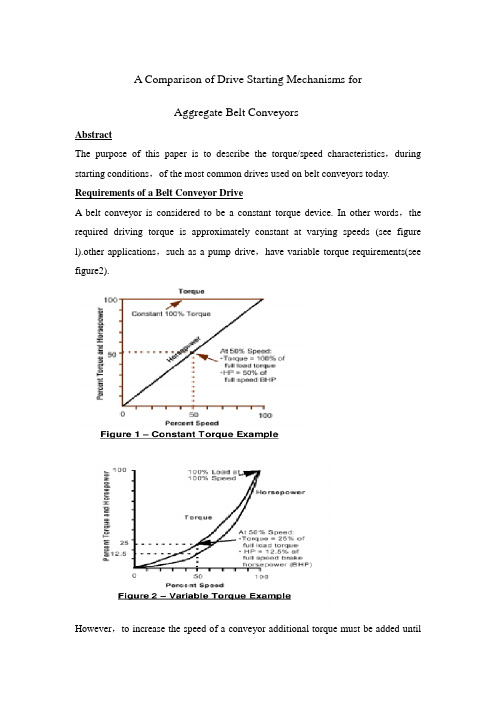
A Comparison of Drive Starting Mechanisms forAggregate Belt ConveyorsAbstractThe purpose of this paper is to describe the torque/speed characteristics,during starting conditions,of the most common drives used on belt conveyors today. Requirements of a Belt Conveyor DriveA belt conveyor is considered to be a constant torque device. In other words,the required driving torque is approximately constant at varying speeds (see figure l).other applications,such as a pump drive,have variable torque requirements(see figure2).However,to increase the speed of a conveyor additional torque must be added untilthe desired speed is obtained. Newton’s Second Law of Motion governs this relationship.∑F m a=The most straightforward example would be a constant acceleration torque(see figure3).In reality the acceleration torque is rarely constant. However,static calculation models as outlined in the Conveyor Equipment Manufacturers Association handbook (CEMA) make this assumption. When using static models the average acceleration torque is estimated over the entire acceleration time and assumed to be linear. Dynamic models,which are beyond the scope of this paper,allow acceleration torque values to vary in magnitude during the acceleration(or deceleration)Period.It should be noted that,given a constant load,a larger acceleration torque results in a faster acceleration time and also higher Peak belt tensions. Conversely,a smaller acceleration torque results in a longer start time and smaller Peak belt tensions. Across-The-Line AC Motor StartTechnically this is the simplest type of drive used on a belt conveyor. In this drive type an AC squirrel cage induction motor is started by simply throwing the contactor and energizing the motor. The resulting output torque,assuming that rated voltage is maintained,is strictly a function of the motor design. NEMA has Provided design standards that define the output torque characteristics of the most commonly used 3 Phase motors up to approximately 250 hp(figure4).In sizes larger than 250 hp manufacturers generally use the NEMA design codes in a relative manner(i.e.,NEMA C has a greater locked rotor torque than a NEMA B motor).The most critical locations on the AC motor speed/torque curve have been named for definition purposes. These common names are provided in figure 5.The most rigorous method of determining average acceleration torque,for static calculations,is to break the curve into several vertical sections,then sum the individual areas under the curve and finally divide by the number of sections.The more common way is to apply the following simplified equation:These static approximation methods work for most belt conveyors but can get the designer into trouble from time to time,especially on long and/or steep and/or fastconveyors. One item that needs to be examined is breakaway torque. Just because the drive provides enough average torque to accelerate the load doesn’t mean that it provides enough torque to break it away from zero speed and get it moving.CEMA defines breakaway torque as twice the torque required to overcome the total friction plus the torque required to lift the load vertically. Locked rotor torque (LRT) needs to be greater than breakaway torque! A good static Program makes this check.In addition to examining the effect that average torque has on the conveyor components the belt designer needs to determine the effect of peak torque. It is not uncommon for the breakdown torque (BDT) of a NEMA C motor to be greater than2.5 times full load torque (FLT).Generally the belting and Pulley manufacturers allowa transient overload of 1.5 times full load operating load. An across-the-line start can easily cause tensions to exceed these maximums. These higher than normal loads can be designed into the conveyor if they are known up front.Considering only average starting torque can cause the conveyor designer to undersize the take-up weight. It is not uncommon for conveyors with across-the-line starters to experience intermittent drive slip. This generally happens when Peak torque (BDT) is input by the drive and the take-up has been sized for average torque but not peak torque. The result can be devastating. When the drive pulley slips during this condition,the tension on the Tl and T2 sides (high and low)of the drive Pulley tries to equalize. This can subject a low tension bend or take-up pulley,just behind the drive pulley,to tensions that approach Tl tension. These Pulleys are rarely,if ever,designed for this load condition and the result is low tension Pulley failure. This condition is easily demonstrated with dynamic analysis.Another common Problem with across-the-line starts is caused by voltage dips during starting. If the power distribution system is not stiff enough to handle the huge inrush currents of an across-the-1ine start,the starting torque of the motors can be reduced to a Point that the conveyor will not start. This is due to the fact that the output torque ofan AC squirrel cage induction motor is reduced by the square of the applied voltage. In other words,a voltage drop of 10%would equate to a torque reduction of 19%. Reduced Voltage StartingThe reduced voltage starting of an AC squirrel cage induction motor is done for two basic reasons:1 .To reduce the inrush current that naturally occurs when a motor is Startedacross-the-1ine. A typical current/speed graph is shown in figure 6.It is not uncommon for the inrush current to be 6 times or more than it is at full load torque. As stated above high inrush currents cause the voltage in a power distribution system to sag. The cost of electrical power distribution equipment can become very high if it needs to be designed to handle the high inrush currents.2 . To reduce Peak motor torque during starting conditions,which subsequentlyincreases acceleration time. By reducing the Peak torques the conveyor components can be designed for lower tension loads. This primarily includes belting,Pulleys and external support structure. This can result in significant cost savings.Two common types of reduced voltage starters are the Current Limiting and the Constant Torque devices.Graphs are included above(figures 7 through 8) that depict the same motor/conveyor application with an Across-The-Line,a limitd Curren, and a constant Torque start. After studying the graphs it becomes apparent that the best use of the limited torque start is to protect the power distribution system from high inrush currents. The constant torque start reduces the high torque Peaks and Protects the conveyor’s mechanical components. In both cases the Start time is increased because the over all magnitude of accelerating torque is reduced. However,neither method will make it easier to start a“hard-to-start conveyor.”Correcting a hard starting conveyor is not areason to use a reduced voltage starter!。

机械手臂应用领域的外文文献以及翻译1. Introduction机械手臂是一种用于执行各种任务的自动化设备,其应用领域广泛。
本文档提供了一些关于机械手臂应用领域的外文文献,并附有简要的翻译。
2. 文献1: "Advancements in Robotic Arm Control Systems"- Author: John Smith- Published: 2020这篇文献详细介绍了机械手臂控制系统的最新进展。
作者讨论了各种控制算法、传感器和执行器的应用,以提高机械手臂的性能和精确度。
3. 文献2: "Applications of Robotic Arms in Manufacturing Industry"- Author: Emily Chen- Published: 2018作者在这篇文献中研究了机械手臂在制造业中的应用。
她列举了多个实例,包括机械手臂在装配、焊接和搬运等任务中的应用,以及通过使用机械手臂能够提高生产效率和质量的案例。
4. 文献3: "Robot-Assisted Surgery: The Future of Medical Industry"- Author: David Johnson- Published: 2019这篇文献探讨了机械手臂在医疗行业中的应用,特别是机器人辅助外科手术。
作者解释了机械手臂在手术过程中的优势,包括更小的切口、更高的精确度和减少术后恢复时间等方面。
5. 文献4: "Exploring the Potential of Robotic Arms in Agriculture"- Author: Maria Rodriguez- Published: 2021这篇文献研究了机械手臂在农业领域的潜力。
作者探讨了机械手臂在种植、收割和除草等农业任务中的应用,以及如何通过机械化技术改善农业生产的效率和可持续性。

机械类外文文献及翻译(文档含中英文对照即英文原文和中文翻译)原文:GEAR AND SHAFT INTRODUCTIONAbstract:The important position of the wheel gear and shaft can't falter in traditional machine and modern machines.The wheel gear and shafts mainly install the direction that delivers the dint at the principal axis box. The passing to process to make them can is divided into many model numbers, using for many situations respectively. So we must be the multilayers to the understanding of the wheel gear and shaft in many ways .Key words: Wheel gear; ShaftIn the force analysis of spur gears, the forces are assumed to act in a single plane. We shall study gears in which the forces have three dimensions. The reason for this, in the case of helical gears, is that the teeth are not parallel to the axis of rotation. And in the case ofbevel gears, the rotational axes are not parallel to each other. There are also other reasons, as we shall learn.Helical gears are used to transmit motion between parallel shafts. The helix angle is the same on each gear, but one gear must have a right-hand helix and the other a left-hand helix. The shape of the tooth is an involute helicoid. If a piece of paper cut in the shape of a parallelogram is wrapped around a cylinder, the angular edge of the paper becomes a helix. If we unwind this paper, each point on the angular edge generates an involute curve. The surface obtained when every point on the edge generates an involute is called an involute helicoid.The initial contact of spur-gear teeth is a line extending all the way across the face of the tooth. The initial contact of helical gear teeth is a point, which changes into a line as the teeth come into more engagement. In spur gears the line of contact is parallel to the axis of the rotation; in helical gears, the line is diagonal across the face of the tooth. It is this gradual of the teeth and the smooth transfer of load from one tooth to another, which give helical gears the ability to transmit heavy loads at high speeds. Helical gears subject the shaft bearings to both radial and thrust loads. When the thrust loads become high or are objectionable for other reasons, it may be desirable to use double helical gears. A double helical gear (herringbone) is equivalent to two helical gears of opposite hand, mounted side by side on the same shaft. They develop opposite thrust reactions and thus cancel out the thrust load. When two or more single helical gears are mounted on the same shaft, the hand of the gears should be selected so as to produce the minimum thrust load.Crossed-helical, or spiral, gears are those in which the shaft centerlines are neither parallel nor intersecting. The teeth of crossed-helical fears have point contact with each other, which changes to line contact as the gears wear in. For this reason they will carry out very small loads and are mainly for instrumental applications, and are definitely not recommended for use in the transmission of power. There is on difference between a crossed heli : cal gear and a helical gear until they are mounted in mesh with each other. They are manufactured in the same way. A pair of meshed crossed helical gears usually have the same hand; that is ,a right-hand driver goes with a right-hand driven. In the design of crossed-helical gears, the minimum sliding velocity is obtained when the helix angle areequal. However, when the helix angle are not equal, the gear with the larger helix angle should be used as the driver if both gears have the same hand.Worm gears are similar to crossed helical gears. The pinion or worm has a small number of teeth, usually one to four, and since they completely wrap around the pitch cylinder they are called threads. Its mating gear is called a worm gear, which is not a true helical gear. A worm and worm gear are used to provide a high angular-velocity reduction between nonintersecting shafts which are usually at right angle. The worm gear is not a helical gear because its face is made concave to fit the curvature of the worm in order to provide line contact instead of point contact. However, a disadvantage of worm gearing is the high sliding velocities across the teeth, the same as with crossed helical gears.Worm gearing are either single or double enveloping. A single-enveloping gearing is onein which the gear wraps around or partially encloses the worm.. A gearing in which each element partially encloses the other is, of course, a double-enveloping worm gearing. The important difference between the two is that area contact exists between the teeth of double-enveloping gears while only line contact between those of single-enveloping gears. The worm and worm gear of a set have the same hand of helix as for crossed helical gears, but the helix angles are usually quite different. The helix angle on the worm is generally quite large, and that on the gear very small. Because of this, it is usual to specify the lead angle on the worm, which is the complement of the worm helix angle, and the helix angle on the gear; the two angles are equal for a 0-deg. Shaft angle.When gears are to be used to transmit motion between intersecting shaft, some of bevel gear is required. Although bevel gear are usually made for a shaft angle of 0 deg. They may be produced for almost any shaft angle. The teeth may be cast, milled, or generated. Only the generated teeth may be classed as accurate. In a typical bevel gear mounting, one of the gear is often mounted outboard of the bearing. This means that shaft deflection can be more pronounced and have a greater effect on the contact of teeth. Another difficulty, which occurs in predicting the stress in bevel-gear teeth, is the fact the teeth are tapered.Straight bevel gears are easy to design and simple to manufacture and give very good results in service if they are mounted accurately and positively. As in the case of squr gears, however, they become noisy at higher values of the pitch-line velocity. In these cases it is often go : od design practice to go to the spiral bevel gear, which is the bevel counterpart of thehelical gear. As in the case of helical gears, spiral bevel gears give a much smoother tooth action than straight bevel gears, and hence are useful where high speed are encountered.It is frequently desirable, as in the case of automotive differential applications, to have gearing similar to bevel gears but with the shaft offset. Such gears are called hypoid gears because their pitch surfaces are hyperboloids of revolution. The tooth action between such gears is a combination of rolling and sliding along a straight line and has much in common with that of worm gears.A shaft is a rotating or stationary member, usually of circular cross section, having mounted upon it such elementsas gears, pulleys, flywheels, cranks, sprockets, and other power-transmission elements. Shaft may be subjected to bending, tension, compression, or torsional loads, acting singly or in combination with one another. When they are combined, one may expect to find both static and fatigue strength to be important design considerations, since a single shaft may be subjected to static stresses, completely reversed, and repeated stresses, all acting at the same time.The word “shaft” covers numerous v ariations, such as axles and spindles. Anaxle is a shaft, wither stationary or rotating, nor subjected to torsion load. A shirt rotating shaft is often called a spindle.When either the lateral or the torsional deflection of a shaft must be held to close limits, the shaft must be sized on the basis of deflection before analyzing the stresses. The reason for this is that, if the shaft is made stiff enough so that the deflection is not too large, it is probable that the resulting stresses will be safe. But by no means should the designer assume that they are safe; it is almost always necessary to calculate them so that he knows they are within acceptable limits. Whenever possible, the power-transmission elements, such as gears or pullets, should be located close to the supporting bearings, This reduces the bending moment, and hence the deflection and bending stress.Although the von Mises-Hencky-Goodman method is difficult to use in design of shaft, it probably comes closest to predicting actual failure. Thus it is a good way of checking a shaft that has already been designed or of discovering why a particular shaft has failed in service. Furthermore, there are a considerable number of shaft-design problems in which the dimension are pretty well limited by other considerations, such as rigidity, and it is only necessary for the designer to discover something about the fillet sizes, heat-treatment,and surface finish and whether or not shot peening is necessary in order to achieve the required life and reliability.Because of the similarity of their functions, clutches and brakes are treated together. In a simplified dynamic representation of a friction clutch, or brake, two in : ertias I and I traveling at the respective angular velocities W and W, one of which may be zero in the case of brake, are to be brought to the same speed by engaging the clutch or brake. Slippage occurs because the two elements are running at different speeds and energy is dissipated during actuation, resulting in a temperature rise. In analyzing the performance of these devices we shall be interested in the actuating force, the torque transmitted, the energy loss and the temperature rise. The torque transmitted is related to the actuating force, the coefficient of friction, and the geometry of the clutch or brake. This is problem in static, which will have to be studied separately for eath geometric configuration. However, temperature rise is related to energy loss and can be studied without regard to the type of brake or clutch because the geometry of interest is the heat-dissipating surfaces. The various types of clutches and brakes may be classified as fllows:. Rim type with internally expanding shoes. Rim type with externally contracting shoes. Band type. Disk or axial type. Cone type. Miscellaneous typeThe analysis of all type of friction clutches and brakes use the same general procedure. The following step are necessary:. Assume or determine the distribution of pressure on the frictional surfaces.. Find a relation between the maximum pressure and the pressure at any point. Apply the condition of statical equilibrium to find (a) the actuating force, (b) the torque, and (c) the support reactions.Miscellaneous clutches include several types, such as the positive-contact clutches, overload-release clutches, overrunning clutches, magnetic fluid clutches, and others.A positive-contact clutch consists of a shift lever and two jaws. The greatest differences between the various types of positive clutches are concerned with the design of the jaws. To provide a longer period of time for shift action during engagement, the jaws may be ratchet-shaped, or gear-tooth-shaped. Sometimes a great many teeth or jaws are used, and they may be cut either circumferentially, so that they engage by cylindrical mating, or on the faces of the mating elements.Although positive clutches are not used to the extent of the frictional-contact type, they do have important applications where synchronous operation is required.Devices such as linear drives or motor-operated screw drivers must run to definite limit and then come to a stop. An overload-release type of clutch is required for these applications. These clutches are usually spring-loaded so as to release at a predetermined toque. The clicking sound which is heard when the overload point is reached is considered to be a desirable signal.An overrunning clutch or coupling permits the driven member of a machine to “freewheel” or “overrun” bec ause the driver is stopped or because another source of power increase the speed of the driven. This : type of clutch usually uses rollers or balls mounted between an outer sleeve and an inner member having flats machined around the periphery. Driving action is obtained by wedging the rollers between the sleeve and the flats. The clutch is therefore equivalent to a pawl and ratchet with an infinite number of teeth.Magnetic fluid clutch or brake is a relatively new development which has two parallel magnetic plates. Between these plates is a lubricated magnetic powder mixture. An electromagnetic coil is inserted somewhere in the magnetic circuit. By varying the excitation to this coil, the shearing strength of the magnetic fluid mixture may be accurately controlled. Thus any condition from a full slip to a frozen lockup may be obtained.齿轮和轴的介绍摘要:在传统机械和现代机械中齿轮和轴的重要地位是不可动摇的。

机械工程专业外文文献及翻译文献一(外文标题)
摘要:
该文献研究了机械工程领域中的某个具体问题。
通过实验方法和数学模型的分析,作者得出了一些有意义的结论。
本文介绍了作者的研究方法和结果,并讨论了其在机械工程领域的应用前景。
翻译:
(将文献的主要内容用简洁准确的语言翻译成中文)
文献二(外文标题)
摘要:
该文献探讨了机械工程领域中的另一个重要问题。
通过实证分析和理论推导,作者提出了解决方案,并对其进行了验证。
本文阐述了作者的方法和实验结果,并探讨了其在实践中的应用潜力。
翻译:
(将文献的主要内容用简洁准确的语言翻译成中文)
文献三(外文标题)
摘要:
该文献研究了机械工程领域中的另一个新颖课题。
作者通过数
值模拟和实验验证,得出了一些有趣的发现。
本文介绍了作者的研
究过程和结果,并讨论了其对机械工程领域的影响。
翻译:
(将文献的主要内容用简洁准确的语言翻译成中文)
总结
本文档介绍了三篇机械工程专业的外文文献,包括摘要和翻译。
这些文献都对机械工程领域中的不同问题进行了研究,并提出了相
关的解决方案和发现。
希望这些文献能为机械工程专业的学生和研
究人员提供有价值的参考和启发。

机械外文参考文献深度学习在机械领域的应用越来越广泛。
本文综述了机械外文参考文献中关于深度学习在机械中的应用研究。
1. Zhang, K., & Kang, L. (2018). Deep learning for inspection and intelligent manufacturing: An overview. Advanced Engineering Informatics, 38, 598-610.这篇综述文章系统地介绍了深度学习在机械检测和智能制造中的应用。
作者回顾了深度学习的发展历程,并探讨了其在工业制造中的潜力和挑战。
2. Chen, D., & Hu, B. (2019). Deep learning for fault diagnosis of rotating machinery: A review. Mechanical Systems and Signal Processing, 107, 49-67.作者对深度学习在旋转机械故障诊断方面的研究进行了综述。
文章介绍了目前广泛应用的深度学习算法,并提供了用于故障诊断的数据集和评估方法。
3. Li, K., et al. (2020). Deep learning-based approachfor intelligent monitoring and prognostics in machining processes. Journal of Manufacturing Systems, 56, 333-345.这篇文章介绍了基于深度学习的智能监测和预测在机械加工过程中的应用。
作者提出了一种新的深度学习框架,用于实时监测和预测机械加工过程中的关键指标。
4. Wang, S., et al. (2017). Machine vision based on deep learning for surface quality inspection in manufacturing processes. Robotics and Computer-Integrated Manufacturing, 46, 151-160.该文介绍了基于深度学习的机器视觉在制造过程中表面质量检测方面的应用。
与机械相关的外文及翻译Multidisciplinary Design Optimization of Modular Industrial Robots by Utilizing High Level CAD Templates1、IntroductionIn the design of complex and tightly integrated engineering products, it is essential to be able to handle interactions between different subsystems of multidisciplinary nature [1]. To achieve an optimal design, a product must be treated as a complete system instead of developing subsystems independently [2]. MDO has been established as a convincing concurrent design optimization technique in development of such complex products [3,4].Furthermore, it has been pointed out that, regardless of discipline, basically all analyses require information that has to be extracted from a geometry model [5]. Hence, according to Bow-cutt [1], in order to enable integrated design analysis and optimization it is of vital importance to be able to integrate an automated parametric geometry generation system into the design framework. The automated geometry generation is a key enabler for so-called geometry-in-the-loop[6] multidisciplinary design frameworks, where the CAD geometries can serve as framework integrators for other engineering tools.To eliminate noncreative work, methods for creation and automatic generation of HLCt have been suggested by Tarkian [7].The principle of high HLCts is similar to high level primitives(HLP) suggested by La Rocca and van Tooren [8], with the exception that HLCts are created and utilized in a CAD environment.Otherwise, the basics of both HLP and HLCt can, as suggested byLa Rocca, be compared to parametric LEGOV Rblocks containing a set of design and analysis parameters. These are produced and stored in libraries, giving engineers or a computer agent the possibility to first topologically select the templates and then modify the morphology, meaning theshape,of each template parametrically.2、Multidisciplinary Design FrameworkMDO is a “systematic approach to design space exploration”[17], the implementation of which allows the designer to map the interdisciplinary relations that exist in a system. In this work, the MDO framework consists of a geometry model, a finite element(FE) model, a dynamic model and a basic cost model. The geometry model provides the analysis tools with geometric input. The dynamic model requires mass properties such as mass, center of gravity, and inertia. The FE model needs the meshed geometry of the robot as well as the force and torque interactions based on results of dynamic simulations.High fidelity models require an extensive evaluation time which has be taken into account. This shortcoming is addressed by applying surrogate models for the FE and the CAD models. The models are briefly presented below. 2.1 High Level CAD Template—Geometry ModelTraditionally, parametric CAD is mainly focused on morphological modifications of the geometry. However, there is a limit to morphological parameterization as follows:•The geometries cannot be radically modified.•Increased geometric complexity greatly increases parameterization complexity.The geometry model of the robot is generated with presaved HLCts, created in CATIA V5. These are topologically instantiated with unique internal design variables. Topological parameterization allows deletion, modification, and addition of geometricelements which leads to a much greater design space captured.Three types of HLCts are used to define the industrial robot topologically; Datum HLCt which includes wireframe references required for placement for the Actuator HLCTs and Structure HLCts, as seen Fig.2.Fig. 2 An industrial robot (left) and a modular industrial robot(right) The names of the references that must be provided for each HLCt instantiation are stored in the knowledge base (see Appen-dix A.4), which is searched through by the inference engine. In Appendix A, pseudocode examples describes how the references are retrieved and how they are stored in the knowledge base.The process starts by the user defining the number of degrees of freedom (DOF) of the robot (see Fig. 3) and is repeated until the number of axis (i) is equal to the user defined DOF.In order to instantiate the first Structure HLCt, two Datum and two actuator instances are needed. References from the two Datum instances help orienting the structure in space, while the geometries of the actuator instances, at both ends of the link, are used to construct the actuator attachments, as seen in Figs. 2 and 3. For the remaining links, only one new instance of both datum and actuator HLCts are required, since the datum and actuator instances from adjacent links are already available.Appendix A.2 shows a pseudocode example of an instantiation function. The first instantiated datum HLCt is defined with reference to the absolute coordinate system. The remaining datum HLCt instances are placed in a sequential order, where the coordinate system of previous instances is used as reference for defining the position in space according to user inputs (see also AppendixA.3). Furthermore, the type of each actuator and structure instance is user defined.Fig. 3 The high level CAD template instantiation process Since it is possible to create new HLCts in the utilized CAD tool, the users are not forced to merely choose from the templates available. New HLCts can be created, placed in the database and parametrically inserted into the models.2.2 Dynamic ModelThe objective of performing dynamic simulation of a robot is to evaluate system performance, such as predicting acceleration and time performance, but it also yields loads on each actuated axis, needed for actuator lifetime calculations and subsequent stress analysis based on FE calculations. Thedynamic model in the outlined framework is developed in Modelica using Dymola, and it constitutes a seven-axis robot arm based on the Modelica Standard library [18].The dynamic model receives input from the geometry model,as well as providing output to the FE model, which is further described in Sec. 2.3. However, to better understand the couplings between the models, the Newton –Euler formulation will be briefly discussed. In this formulation, the link velocities and acceleration are iteratively computed, forward recursivelyWhen the kinematic properties are computed, the force and torque interactions between the links are computed backward recursively from the last to the first link2.3 FE Surrogate ModelTo compute the structural strength of the robot, FE models for each robot link is created utilizing CATIA V5, see Fig. 4. For each HLCt, mesh and boundary conditions are manually preprocessed in order to allow for subsequent automation for FE-model creation. The time spent on preprocessing each FE-model is thus extensive. Nonetheless, the obtained parametric FE-model paves way for automated evaluation of a wide span of concepts. Each robot link is evaluated separately with the load conditions extracted from the dynamicmodel. The force (fi-11and fi) and torque (ţi-1and ti) are applied on the surfaceswhere the actuators are attached.2.4 Geometric Surrogate Models.Surrogate models are numerically efficient models to determine the relation between inputs and o utputs of a model [19]. The input variables for the proposed application are the morphological variables thickness and link height as well as a topological variable actuator type. The outputs of the surrogate models are mass m, Inertia I, and center of gravity ri,ci.To identify the most suitable type of surrogate model for the outlined problem, a range of surrogate models types are created and evaluated using 50 samples. The precision of each surrogate model is compared with the values of the original model with 20 new samples. The comparison is made using the relative average absolute error (RAAE) and relative maximum absolute error (RMAE) as specified by Shan et al. [20], as well as the normalized root mean square error (NRMSE), calculated as seen in Eq. (3). All precision metrics are desired to be as low as possible, since low values mean that the surrogate model is accurateThe resulting precision metrics can be seen in Appendix B and the general conclusion is that anisotropic kriging [21], neural networks [22], and radialbasis functions [23] are the most promising surrogate models. To investigate the impact of increasing number of samples, additional surrogate models of those three are fitted using 100 samples, and the results compiled in Appendix B. The resulting NRMSEs for 50 and 100 samples for anistotropic kriging, neural networks, and radial basis functions can be seen in Fig.5. The figures inside the parentheses indicate the number of samples used to fit the surrogate models.Fig. 5 Graph of the NRMSEs for different surrogate models,fitted using 50 and 100 samplesAccording to Fig. 5, anisotropic kriging outperforms the other surrogate models and the doubling of the number of samples usedfor fitting the surrogate model increases the precision dramatically.2.5 FE Surrogate ModelsFor generating FE surrogate models, the anisotropic kriging was also proven to be the most accurate compared to the methods evaluated in Sec. 2.4. Here, one surrogate model is created for each link. Inputs are thickness,actuators, force (fi-11and fi) and torque (ţi-1and ti). The output for eachsurrogate model is maximum stress (MS).A mean error of approximately 9% is reached when running 1400 samples for each link. The reason for the vast number of samples, compared to geometry surrogate models, has to do with a much larger design space.利用高水平CAD模板进行模块化工业机器人的多学科设计优化1 介绍指出,除了规则,基本上所有的分析都需要信息,而这些信息需要从一个几何模型中提取。
机械手臂外文文献翻译、中英文翻译、外文翻译外文出处:《Manufacturing Engineering and Technology—Machining》附件1:外文原文XXXRobot XXX decades as high-XXX branch of industrial robots. It features can be programmed to perform tasks in a variety of expectations, in both structure and performance advantages of their own people and machines, in particular, XXX the work in the field of national economy and there are broad prospects for development. With the development of industrial automation, there has been CNC machining center, it is in reducing labor intensity, XXX, the upper and lower common in CNC machining processesmaterial, usually still use XXX relay-controlled semi-automatic device. The former time-consuming and labor intensive, inefficient; XXX, require more relays, XXX, XXX interference, XXX, XXX Programmable Logic Controller PLC-controlled robot control system formaterials up and down movement is simple, circuit design is reasonable, with a strong anti-jamming capability, ensuring the system'XXX, reduced maintenance rate,and XXXmechanics, mechanics, XXX, XXX, XXX and other fields of science, is a cross-disciplinary XXX.First, an overview of industrial manipulatorRobot is a kind of positioning control can be automated and can be re-programmedto change in multi-functional machine, which has multiple degrees of freedom can beused to carry an object in order to XXX China, plastic products industry, although still a labor-intensive, XXX1Europe and the United XXX, XXX-intensive South China, East China's coastal areas, XXX, because they have to face a high turnover rate of workers, as well as for theworkers to pay work-related injuries XXX.With the rapid development of China's industrial production, especially the reformand XXX workpiece handling, steering, XXX brazing, spray gun, wrenches and other tools for processing and assembly operations since, which has more and more attracted our attention. Robot is to imitate the manual part of the action,according toa given program, track and requirements for automatic capture, XXX.In real life, you will find this a problem. In the machine shop, the processing of parts loading time is not annoying, and labor productivity is not high, the cost of production major, and sometimes man-made incidents will occur, resulting in processing wereinjured. Think about what could replace it with the processing time of a tour as long as there are a few people, and can operate 24 hours saturated human right? The answeris yes, but the robot can come to replace it.XXX can increase XXX; XXX, ensuring product quality, to achieve safe production; particularly in the high-temperature, high pressure, low temperature, low pressure, dust, explosive, XXX the normal working people. Here I would like to think of designing a robot tobe used in actual production.XXX power: pneumatic robot refersto the compressed air as power source-driven robot. With pressure-driven and other energy-driven comparison have the following advantages: 1. Air inexhaustible, used XXX, does not require recycling and disposal,do not pollute the XXX. (Concept of environmental protection) 2. Air stick is small, the pi2peline pressure loss is small (typically less than asphalt gas path pressure drop of one-thousandth), to facilitate long-distance transport. 3. Compressed air of the working pressure is low (usually 4 to 8 kg / per square centimeter), and therefore moving the material components and XXX. With the hydraulic transmission, compared to its faster action and reaction, which is one of the advantages pneumatic outstanding. 5. The air cleaner media, it will not degenerate, not easy to plug the pipeline. But there are also places where it fly in the ointment: 1. As the compressibility of air, XXX the work, XXX as the precision of the velocity and not easily controlled. 2. As the use of low atmospheric pressure, the output power can not be too large; in order to increase the output power is bound to the structure of the entire pneumatic system size increased.With pneumatic drive and compare with other energy sources drive has the following advantages:Air inexhaustible, used XXX, without recycling anddisposal, do not pollute the XXX or a small amount of leakage would not be a XXX of air is small, the pipeline pressure loss also is very small, easy long-distance transport.The lower working pressure of compressed air, XXX general, reciprocating thrust in 1 to 2 tons XXX.Compared with the hydraulic transmission, and its faster action and reaction, XXX.Clean air medium, it will not degenerate, not easy to plug the pipeline. It can be safely used in flammable, XXX.Second, XXX, mechanical handRobot in the form of a variety of forms, some relatively simple, some more complicated, but the basic form is the same as the composition of the , Usually by the implementing agencies, transmission systems, control systems and auxiliary devices compose3d.1.Implementing agenciesXXX hands, wrists, arms, pillars. Hands are crawling institutions, is used to clamp and release the workpiece, and similar to human fingers, XXXXXX used to support the arm can also be made mobile as needed.2. TransmissionXXX, hydraulic transmission, XXX.3. Control SystemManipulator control system's main role is to control the robot according to certain procedures, direction, position, speed of action, a simple mechanical hand is generallynot set up a dedicated control system, using only trip switches, relays, control valves and circuits can be achieved dynamic drive system control, so that XXX of action. Action will have to use complex programmable robot controller, the micro-computer control.Three, XXX characteristicsXXX: the first is the general machinerydoes not require manual hand. It is an independent not affiliated with a particular hostdevice. It can be programmed according to the needs of thetask to complete the operation of the provisions. It is XXX, alsohas general machinery, memory, XXX second categoryis the need to manually do it, called the operation of aircraft. It originated in the atom,military industry, first through the operation of machines to complete a particular job,XXX such as the Moon. Used in industrial manipulator also fall into this category. The third category is dedicated manipulator, the XXX auto4matic lines, to solve the machine up and down the XXX known as the "Mechanical Hand", which is the host of services, from the host-driven; exception of a few outside the XXX, XXX.Main features:First, mechanical hand (the upper and lower material robot, assembly robot, handling robot, stacking robot, help robot, vacuum handling machines, vacuum suction crane,labor-saving spreader, pneumatic balancer, etc.).Second, cantilever cranes (cantilever crane, electric chain hoist crane, air balance the hanging, etc.)Third, rail-type transport system (hanging rail, light rail, single girder cranes, double-beam crane)Four, industrial machinery, application of handXXX of the production process developed a new type of device. In recent years, as electronic technology, especially computer extensive use of robot development and production of high-tech fields has XXX, XXX, XXX.Although the robot is not as flexible as staff, but it has to the continuous duplicationof work and labor, I do not know fatigue, not afraid of danger, XXX characteristics when compared with manual large, therefore, mechanical hand has been of great importance to many sectors, and increasingly has been applied widely, forexample:(1) Machining the workpiece loading and unloading, especially in the automatic lathe, combination machine tool use is more common.(2) XXX industry, it can beused to assemble printed circuit boards, XXX industry It can be used to assemble parts and components.(3) The working conditions may be poor, monotonous, repetitive easy to sub-fatigu5XXX.(4) XXX, XXX, XXX..(5) XXX.(6), XXX and testing.Help mechanical hands: also known as the balancer, balance suspended, labor-savingspreader, manual Transfer machine is a kind of weightlessness of manual load system,a novel, time-XXX,belonging to kinds of non-standard design of series products. Customer application needs, XXX of the automatic machinery, it can be a fixed program draws﹑XXX. Application of robot can replace the peopleengaged in monotonous﹑XXX, XXX of production, instead of people in hazardous XXX, XXX personal safety. The late 20th century, 40, the United XXX experiments, the first use of radioactive material handling robot, human robot in a safe room to XXX 50 years later, XXX, for the temperatures, polluted areas, and loading and unloading to take place the work piece material, but also as an auxiliary device in automaticmachine tools, machine tools, automatic production lines and processing center applications, the completion of the upper and lower material, or From the library take place XXX operation. Robot body mainly by the hand and sports XXX with the use of hands and operation of objects of different occasions, often there are clamping﹑XXX﹑﹑XXX﹑XXX, generally 2 to 3 degrees of XXX industry, machinery manufacture, XXX some of the staff and arm motor function, a fixd procedure for the captu6re, handling objects or operating tools, automatic operation device. It can replace human labor in order to achieve the production of heavy XXX the personal safety, which is XXX, metallurgy, electronics, light industry and nuclear power sectors. Mechanical hand tools or other XXX used for additional devices, such as the automatic machines or automatic production line handling and transmission of the workpiece, XXX centers, etc. generally do not have a separate control device. Some operating devices XXX.XXX and sports XXX. Task of hand is holding the workpiece (or tool) components, according to grasping objects by shape, size,weight, material and XXX structural forms, such as clamp type,type and adsorption-based care such as holding. Sports organizations, XXX (swing), XXX the required action, to change the location of objects by grasping and posture.Robot is the automated production of a kind used in the process of crawling and moving piece features automatic device, which is XXX a new type of device. In recent years, as electronic technology, especially computer extensive use of robot development and production of high-tech fields has XXX, XXX, XXX. Robot can replace humans completed the risk of duplication ofboring work, to reduce human XXX widely, in the machinery industry, it can be used for parts assembly, work piece handling, loading and unloadingXXX component of the FMC. The machine tool equip7XXX a flexible manufacturing cell, it was adapted to small and medium volume production, you can save a huge amount of the work piece conveyor device, compact, and adaptable. When the work piece changes, flexible production system is very easy to change will help XXX, improve product quality, and better adapt to market XXX, China'XXX isa certain distance, application andindustrialization of the size of the low level of robot research and development of a direct impact on raising the level of automation in China, from the economy, XXX, the study of mechanical hand design is very meaningful.8附件1:外文资料翻译译文呆板手机械手是近几十年发展起来的一种高科技自动化生产设备。
关于机械的英文文献以下是一篇有关机械的英文文献:Title: The Development and Applications of Mechanical SystemsAbstract:Mechanical systems are used in a wide range of applications from everyday household items to complex industrial machinery. Mechanical systems are composed of various mechanical components that interact with each other to perform mechanical tasks. The development of mechanical systems has been a continuous process, improving over time with the introduction of new technologies and materials.Mechanical systems can be classified into three main categories: power transmission systems, motion control systems, and structural systems. Power transmission systems transmit power from one location to another, either through a series of gears or a belt drive system. Motion control systems control the movement of a mechanical object through the use of servo motors, linear actuators, and other components. Structural systems provide the necessary support and stability for mechanical systems.One of the most important applications of mechanical systems is in the manufacturing industry. Mechanical systems are used in everything from assembly line machinery to robotic systems for welding, painting, and other tasks. Mechanical systems are also commonly used in transportation systems, including automobiles, airplanes, and trains.In recent years, the development of smart mechanical systems has become an area of focus in the research and development of mechanical systems. Smart mechanical systems are designed to be more autonomous and can include features such as sensors, actuators, and advanced control systems. These features allow the mechanical system to operate more efficiently and autonomously.Overall, the development and applications of mechanical systems have played a significant role in the advancement of modern society. As technology continues to evolve, so too will the capabilities of mechanical systems, allowing for new and innovative applications in a wide range of fields.Keywords: mechanical systems, power transmission, motion control, structural systems, manufacturing, smart mechanical systems, sensors,actuators, control systems.。
V o1.13 No.2 Joumat of Southwest Jiaotong University Nov.2005 Article I D:1005-2429(2005)02-0103-10An Intelligent Master Model of Computer Aided Process Planning for LargeComplicated StampingsZheng linqiao(郑金桥) Wang Yilin(王义林) Li Zhigang(李志刚) State Key La boratory of Die&Mold Technology,Huazhong University of Science&Technolog y,Wuhan 430074,ChinaAbstrac tProcess planning for large complicated stampings is more complicated,illegi ble and multiform than that for common stampings.In this paper,an intellige nt master model of computer aided process planning (CAPP) for large complic ated stampings has been developed based on knowledge based engineering (KB E) and feature technology.This innovative model consists of knowledge base (KB),process control structure(PCS),process information model (PIM),multid isciplinary design optimization (MDO),model link environment (MLE) and sim ulation engine (SE),to realize process planning,optimization,simulation and management integrated to complete intelligent CAPP system.In this model,K BE provides knowledge base,pen architecture and knowledge reuse ability to deal with the multi-domain and multi-expression of process knowledge,and for ms an integrated environment.With PIM ,all the knowledge consisting of objects,constraints,experience and decision-makings is carded by object-orient ed method dynamically for knowledge—reasoning.PCS makes dynamical knowl edge modified and updated timely and accordingly.MLE provides several meth ods to make CAPP system associated and integrated.SE provides a programma ble mechanism to interpret simulation course and result.Meanwhile,collabora tive optimization,one method of MDO,is imported to deal with the optimiz ation distributed for multiple purposes.All these make CAPP system integrated and open to other systems,such as die design and manufacturing system.Key words Large complicated stampings;Process planning;Knowledge-based engineering;Intelligent master model IntroductionCommonly,large complicated stampings refer to sheet metal parts,such as automobile panels,which are complicated in shape with groups of free form S urfaces,large in size and can be manufactured by stamping processes.The for ming processes can be considered as combination of some common stampings,such as irregular drawing,flanging/bending,notching,embossing and pier cing.The existing expert computer aided process planning (CAPP) systems,mo stly about common sheet metal such as axisymmetric and non-axisymmetric d eep drawings ,complex bendings and shearings,were limited to narrow applic ation and weak in intelligent technique[ 1-5] The CAPP of large complicated s tampings is more complicated and illegible than common sheet metal stampin g,and is generally dependent on engineers experience to complete.Generally,the organization,control and exccution of CAPP aIe complex co urses.Many researchers have dived into this field or sub.fields and their inte grations.Kang et a1.[6] proposed an approach to interlink design and proc ess planning by representing manufacturing inform ation together wim part geo metry in an integrated product model based on the Standard for the Exchange of Product(STEP).This framework contributed towards removing the main barri er to computer—automated process planning.Despite the achievements in handl ing manufacturing information,recognition of relevant features of complex shap es still remains a bottleneck.Case et a1.[7] presented a methodology using the feature—based representation with the capture of designer’s intents related t o component geometries,which was potentially useful for engineering,proces s planning and manufacturing an alysis.Gao et a1.[8] developed a mathema tical model to create a processplanning model automatically using machine feat ures,feature mapping or conversion.Paris an d Brissaud[9] implemented a d esign model in process planning view,which permitted a good exchange and a co—ordination.Consequently,feature technology is an available method to sol ve the integration of CAD and CAPP for large complicated stampings,but ma ture feature extraction and representation methods,as well as the consistency a nd association of information transition,are still key problems for seamless int erface between design and process planning automation.Furthermore .A1一Ahmaxi et a1.[10] presented an GI simulation integrated modeling method (GI—SIM ),which combined three concepts of modeling(co ncep—tual,functional and simulation)in an integrated structure.It enabled a s ystem analyst and designer to build system models from the basic functional s pecifications and the lowest levels of activity centre,which could be translated into a simulation modeling tool to evaluate design and process performance.He avey et a1.[11] introduced EPSYLON process modeler to provide a tool tailor ed to modeling manufacturing operations using high semantic mod eling,and a manufacturing operations description tool to integrate with other software mod ules such as simulation,monitoring and scheduling to support day—to—day op erations of a facility.Above all,the simulation and planning are regarded as t wo courses independently,or sometimes simulation tool is blocked in process planning,but lots of knowledge existent but ambiguous are not discovered fro m simulation to promote process planning.High level integration of the two is still difficult to realize.Additionally,Zhao et a1.[10] had researched a cooperative agent model a nd developed an experimental machining cooperative computer aided process pl anning(CoCAPP)system.The system utilized cooperative and cordination mecha nisms built into distributed agents with their own expert systems.It is flexible and upgradeable,but the cooperation of each agent is still dificult to realize fo r the standalone expert systems to perform the entire process planning.Th ou gh many researchers have explored some methods for process planning and sub —system integration,the following problems still exist[1-5]:(1)Product design and process information representation are not suitable for all kinds of knowledge.(2)For lack of control and management,information is often modified and updated inconsistently.(3) For lack of association and cooperation,the information transition is often broken.(4) Scarcely is there any knowledge mining from simulation to promote process planning.All these problems seriously affect the intelligent and optimization ability of CAPP for large complicated stampings.To solve these problems,the master m odel of CAPP has to be explored and innovated[13,14] .In this paper,the con ception of intelligent master model of process planning based on knowledge is proposed to implement intelligent and integrated CAPP.The intention is to de velop an intelligent master model to support stamping CAPP system for planni ng,design and analysis.Th is intelligent master model integrates the process and relevant technologies to realize rapid instantiation and evaluation of the for ming processes based on sim ulation,and obtain optimi zed process plans.1 Knowledge Based Intelligent M aster M odel for CAPPTo solve all the problems mentioned above.We need a model with functions,methods and management to realize inner or high level integration of CAPP.For the integrated functions.inform ation stream s,data,and process flows,the IDEF(ICAM definition method,in which ICAM stands for integrated comp uter aided manufacturing) modeling method had been researched and applied fr equently[15-18].The model was developed by the US Air Force to provide an integrated suite of tools for the purpose of modeling activities within an organi zation.This approach involved IIDEFD(functiona1),IDEF1(information),IDE FlX (data),IDEF3(process flow and object state description capture),IDEF4 (o bject—oriented design),and IDEF5(ontology description capture)·This modeling approach had helped people involved in improving manufacturing productivity to understand different aspects of a system ,but it was only to frame the inpu t/output streams,functions,sub—system and architectures,and could not aff ord basic methods or concepts on how to implement and realize the integration and consistency. Subsequently.Gayretli [19] demonstrated a prototype system for the evaluation and optimization of manufacturing processes.This model had embodied a CAD solid modeling system ,user interface,design representatio n,consistency manager,constraint—based system,process optimization and ma nufacturability analysis.and various knowledge sources.This system assisted d esigners in designing products concurrently,selecting manufacturing processes,and evaluating and optimizing those processes in terms of various product life —cycle requirements and user constraints by avoiding inconsistencies.The prop osed model and system gives a reference for the research of this paper,and itis one of feasible methods for the integration.In 2000, Lutters [3] proposed a reference model and an architecture to integrate with design and production pl anning.The reference model represented a system as an organization in term s of its structure of relatively independent,interacting components and the global ly defined tasks of these components,while the architecture was applied as the basis for the im plementation and realization of the intended functionality of t he system.In his research,Lutters considered that information was the kernel to guide product life cycle,and inform atiOn management could become the k ey to the integration of all processes.This provided a concept of integration f or CAPP system.Strictly.the CAPP system for large complicated stampings is a bridge to int egrate product CAD and die CAD /CAM ,which includes two fields tasks a s process sequences for stamping and 3D detail design for work.,pieces an d relevant die CAD /CAM .The process sequences are to determine the nece ssary forming processes and their sequences in order to produce a particular pa rt economically and competitively,while the detail design is to tl1ink out all process parameters for each process and design rational and practicable 3D wor k—pieces for each process an d relevant stamping die.Mostly,numerical simu lation tool is always adopted to check design and detect forming defects virtua lly.To develop intelligent CAPP system for large complicated stampings,we s hould complete these three tasks with planning,design and simulation systemat ically in an integrated environment.Furthermore, the process planning for large complicated stampings requires knowledge from diverse fields,such as metal forming technology,metal forming mechanics,modem design methodology,nu merical simulation technology and artificial intelligence,which bring it into bei ng a multidisciplinary design.Therefore ,knowledge is considered as the ker nel an d essential for process planning,geometry objects design,and kn owl edge translation to realize integrated and reduce the dependence on engineers o r experts in this paper.Accordingly,the master model of CAPP not only has to solve the problems form the multidiscipline,such as expression and applicat ion of knowledge,controlling of process,information integration,optimization and numerical simulation,etc.to implement and integrate to process planning and freeform surface design,but also has to control,fram e and execute CAP P system in system leve1.The intelligent master model(IMM)of process planning for large complicated st ampings is composed of knowledge base.process control structure(PCS),proc ess information model(PIM),multidisciplinary design optimization(MDO),mode l link environment (MLE)and simultion engine(SE),which are integrated on kn owledge based engineering(KBE).The structure of the IM M is shown in Fi g.1.The IMM of process planning is not only the foundation of intelligent C APP for large complicated starnpings,but also the integration of knowledge an d methods,which make KBE system to combine with the process planning.I n this model,KBE acts as a kn owledge source to drive PCS,PIM ,and M LE to make process planning intelligent and associative.At the same time,theglobal optimization of CAPP can be decomposed into several basic optimizati on problems,an d MDO can integrate the optimized results of basic problems to obtain the optimal planning.The MLE and numerical simulation engine serve for evaluation,modification and adaptive planning.2 Key Technologies in IMM2.1 Application of KBE to large complicated stampingsKBE is one of innovative methods of artificial intelligence for engineering design,which was advanced in 1980’s.So far,there is no generally accepted and mature definition for KBE yet.However,it is recognized that KBE is an innovative intelligent method,which can resolve engineering problems,and realize inheritance ,integration,innovation and man agement of domain kn owledge through the drive and multiplication of knowledge.It provides an open architecture and reuse ability of knowledge,which can deal with multi·-domain and multi·-expression of knowledge,and can form an integrated environment[ 21].A KBE application is further specialized,and typically has the following components as geometry,configuration,and engineering knowledge in high degree integration.KBE is sometimes termed “rule—based engineering”,as within the discipline knowledge is often represented by rules.These rules may be mathematical formulae or conditional statements,and although simple in concept;they may be combined to form complex and powerful expressions.Major companies already realized significant benefits from the use of KBE .Based on product information,process knowledge,expert experience and manufacturing resource,the process planning for large complicated stampings should complete a practical forming plan through analysis,computing,decision—making and judgment.During planning.the knowledge that has to be dealt with involves geometric and non—geometric information of the product,planning rules,forming constraints,expert experience and simulation result.Furthermore ,it is necessary to establish the link with standard process planning rules,materials database,planning hand-books and analysis tools.KBE plays a very important role in process planning,including acquisition and expression of knowledge,process modeling,organizing,communication and knowledge reasoning,decisionmaking and controlling ofprocess.It not only provides comprehensive knowledge to support process planning,but also provides available technology and environment to integrate all key technologies.When the planning model is established based on kn owledge,a new proces s planning instantiation can be rapidly created using multi—reasoning methods,and the results ofthe process can be gotten automatically.It is the foundation t o realize intelligent and associative process planning,based on which the result s of the process planning wil be updated automatically and timely if any modi fication is made.2.2 Process information modelThe process planning of large complicated stampings is a dynamic process.The PIM must involve all data,such as process planning data,analysis data,die designdata,circumstance,etc.The basic knowledge expression of the model should have adaptability to the changes of geometry,attribute,features,constraints and the way of thinking.Using knowledge multi—expression format of KBE technology,the integrated PIM for large complicated stampings is built based on feature model,which is shown in Fig.2.Object—oriented method and feature technology are adopted to form the model basically.Th em ale three basic classes of features,i.e.stamping design features,operation features,and sequence features,in which process knowledge(e.g.parameter,rules,experience) acts as the rules and attributes ofthe ohjects.Using geometry feature extraction method,the Stamping design features,such as main forming feature (e.g.drawing),flange,hole,emboss,and so on,can be extracted from a 3D solid model,and defined as UG/UDO(Unigraphics/user defined object)first.Relevant appropriate operations and tIleir assorted ones Can then be assigned from stamping design feature of product using a set of rules witIl decision—making tree and model·-based reasoning methods of feature·-operation criterion.The hiberarchy and fram ework of the product model and semantic network of feature—operation—tools are used to establish the relationship informa-tion for PIM .With PIM and the knowledge encapsulated in objects or the decision·-making knowledge procedures,the process planning can be completed through corresponding sets of knowledge-reasoning.This model is a dynamic expan ded information model,in which the information can be added and updated along with the process of planning.The information management and control is a part of PCS in the IMM of process planning;it can monitor the change or modification of process planning,an d update the inforrnation timely to assure the PIM an d process planning synchronization.In the process planning,the information management and control begins its control and judgment from the time that the stamping design features have been created till the planning ends.2.3 Peocess control structureProcess planning for large complicated stampings generally involves stamping features extraction,operation features definition,process planning and detail design for sequences.The PCS is a key point to ensure process planning integrated and consistent,which manages PIM and process planning to generate form‘ ing plans and detail design,and control the changes ofthe planning.In this paper,the process planning of a product is defmed as a project.The project control can create a process planning project,insert the part to a suitable position of the project,and decompose the process planning task into subtasks.In IMM and process planning,all the process features are flagged by specific symbols and their data structures,or expressed by the given geometries of the product or process work-pieces.According to the knowledge expression and decision-making rules,the planning process control can set up the PIM based on features and their data structures,monitor planning process,feed the planning inform ation and changes back to IMM ,an d control information transfer.The process planning is a dynamic process of inform ation flow and transfer.The information link control ensures process planning inform ation to be associative and consistent.The added,extended,and modified inform ation and their effects on the planning can be fed back to PIM and IMM so that the information of process plan ning can be updated timely and shared by diferent parts of the system.For the complicated,mass geometrical information involved during the process planning,the links between features,or result symbols,and product geometric inform ation have to be dealt with.The graphics link control can monitor and controlthe links and transfer of the graphics information between different parts of process planning.Detail design control is used for the detail design of sequences,and an appropriate 3D control model should be set up first.Using corresponding knowledge,engineering computation and the top level data in the model of each work-piece,detail design control can complete 3D work—pieces design.In IMM ,the parts of PCS come into being dynamically along with the proceeding of process planning.If one part of PCS is created,it will monitor and control the relevan t plan ning and inform ation subsequently.When some results of process planning are deleted,the coresponding PCS part will fade away accordingly.2.4 M odel link environment and simula-tion engineFor process planning is related to several domains knowledge,to achieve intelligent planning for complicated stampings,three problems ned to be solved ,i.e.the link be twen process planning procedures,the geometry link betwen product and detail design ,the link betwen 3D model of work—pieces and simulation mod e1.The MLE provides several methods to deal with all these links,i.e.parametric variable link ,data structures link,geometrical link,and model link.Process planning is an iteration course of design and modification.To ensure information consistency,data structure finks utilize data structure information,UG /UDO,and process Status control variable to update relative information and PIM automatically and timely.During process planning,geometrical link using UG/W A VE and UG/UDO assign product geometry into each sequence for the initial work—piece.In detail design,geometrical link keeps geometrical information consistent betwen 3D intermediate work—pieces.Furthermore,the variable links of parameters make addendum ,blank-holder an d draw—bead of the drawn part linked together based on the control mode1.In the same way,the links betwen flange and the trimming line and those betwen drawing and trimming line are realized.At the same time,the correlative information of detail designs is updated timely through links of data structure an d model link ,and is fed back to IMM.When detail design is finished.numerical simulation is always conducted to check the feasibility of forming and ascertain defects for remedy modification or design .The existing CAD and finite element an alysis systems do not use a unified product/process model,which leads to separate creations of the data mod els.The KBE method unifies the engineering intention and the data models,which allows the existing or novel design to be evaluated .In MLE,as shown in Fig.4,a 3D model of detail design and an analysis model are linked through MLE and IMM.These designsolutions can then be transferred themselves to the correct form for the analysis system.Auto-meshing is achieved by UG/structure that meshes the 3D model with respect to the analysis solution required ,materials and processes.Then simulation tool such as FEM simulates the process of drawing,and the SE searches information available from simulation results.SE is an important part of MLE,in which simulation tools are encapsulated.In this paper,the SE consists of analyses,explanation and knowledge mining method and can be used as a reusable an d integrated plug—in—tool,and thus provides a programmable mechanism to interpret and control the simulation course an d result.The defects such as wrinkle,cracking,attenuation and spring—back,can be searched by the SE from the strain of every element.The locations of the defects can also be tracked from the coordinate points betwen the element and the draw part.Finally,the substantial parameters such as drawbead restraining forces,press forces,and param eters of addendum (e.g.,die diverse radius,punch radius,height of stretch wall,et a1.)can be optimized.The mined knowledge can be fed back to IMM and 3D detail design mod el through MLE and PCS to realize adaptive design .For example,the precise blank is determined from simulation,and the parameters and data are obtained in UG/CAD to design blank part.3 Multidisciplinary Design OptimizationThe optimization of process planning for large complicated stampings involves different types of objects at different stages.The MDO can divide the complicated optimization problem of process planning into several basic optimization issues distributed,and the basic optimization can be solved by corresponding methods.MDO can get the integrated global optimal result from the optimization solutions of the basic issues by collaboration capacity .During process planning,different process routes are obtained by different planners;therefore the best process route is selected according to the batch of production,design and manufacture of stamping dies,enterprise resource,cost,etc.During operations planning,the equipment and operators for each operations are assigned to meet the design specifications to achieve the minimum machining time and the maximum eficiency.When the detail design of sequence is finished,it is dificult to check whether or not the design meets product specifications economically.The sim ulation analyses and optimization are implemented to find defects and to obtain optimal design.The above optimizafions comprise the integrated optimization of process planning for large complicated stampings,which are associated with and restricted by each other.From all these,the collaborative optimizafion(CO),one method of MDO,is imported to deal with the optimization distributed and associated.Finally,the integrated optimization of process planning is reahzed for multipurpose(best—quality,maximizing eficiency,minimizing cost and time,etc).4 Integration of Key Technologies in IMMGenerally,the forming of a large complicated stamping always includes several operations,such as drawing,trimming,flanging,piercing,re—striking,etc.Among the operations,drawing,trimming and flanging are the main operations,an d the otheroperations are auxiliary ones,which work together with the main operations to generate the complex shape of the part.Based on knowledge,the process planning should provide a practical forming plan through analysis,computing,decision—making and judgment.The prototype CAPP system for large complicated stampings has been developed based on the itelligent master model,which chooses UG/CAD with UG/KF (Unigraphics/knowledge fusion) module as the development enviroment,VC and UG/KFL (Unigraphics/knowledge fusion language)as the implementation languages,and acess as its database.Some typical issues in CAPP system for large complicated stampings are shown in Fig.5.Beginning with a 3D product model,the CAPP system extracts stamping features from the basic geometrical elements and assigns them with forming operations based on stamping criterions to establish PIM .Then it determines the optimum process sequence required to form the final product from blank according to knowledge of operations combination and do-after.With ordered forming processes,the dies,machinery and other fixtures are mapped.Finally,the detail design for each process is done for relevant die face,and the schedule of process sequence and relevant tools or press machines are generated to guide the product forming,while the SE is used to predict defects and optimize the design.。