机械设计外文翻译中英文
- 格式:doc
- 大小:26.96 KB
- 文档页数:8
外文原文Mechanical DesignAbstract:A machine is a combination of mechanisms and other components which transforms, transmits. Examples are engines, turbines, vehicles, hoists, printing presses, washing machines, and movie cameras. Many of the principles and methods of design that apply to machines also apply to manufactured articles that are not true machines. The term "mechanical design" is used in a broader sense than "machine design" to include their design. the motion and structural aspects and the provisions for retention and enclosure are considerations in mechanical design. Applications occur in the field of mechanical engineering, and in other engineering fields as well, all of which require mechanical devices, such as switches, cams, valves, vessels, and mixers.Keywords: Mechanical Design mechanisms Design ProcessThe Design ProcessDesigning starts with a need real.Existing apparatus may need improvements in durability, efficiency, weight, speed, or cost. New apparatus may be needed to perform a function previouslydone by men, such as computation, assembly, or servicing. With the objective wholly or partlyIn the design preliminary stage, should allow to design the personnel fully to display the creativity, not each kind of restraint. Even if has had many impractical ideas, also can in the design early time, namely in front of the plan blueprint is corrected. Only then, only then does not send to stops up the innovation the mentality. Usually, must propose several sets of design proposals, then perform the comparison. Has the possibility very much in the plan which finally designated, has used certain not in plan some ideas which accepts.When the general shape and a few dimensions of the several components becomeapparent, analysis can begin in earnest. The analysis will have as its objective satisfactory or superior performance, plus safety and durability with minimum weight, and a competitive cost. Optimum proportions and dimensions will be sought for each critically loaded section, together with a balance between the strengths of the several components. Materials and their treatment will be chosen. These important objectives can be attained only by analysis based upon the principles of mechanics, such as those of static for reaction forces and for the optimum utilization of friction; of dynamics for inertia, acceleration, and energy; of elasticity and strength of materials for stress and deflection; of physical behavior of materials; and of fluid mechanics for lubrication and hydrodynamic drives. The analyses may be made by the same engineer who conceived the arrangement of mechanisms, or, in a large company, they may be made by a separate analysis division or research group. Design is a reiterative and cooperative process, whether done formally or informally, and the analyst can contribute to phases other than his own. Product design requires much research and development. Many Concepts of an idea must be studied, tried, and then either used or discarded. Although the content of each engineering problem is unique, the designers follow the similar process to solve the problems. Product liability suits designers and forced in material selection, using the best program. In the process of material, the most common problems for five (a) don't understand or not use about the latest application materials to the best information, (b) failed to foresee and consider the reasonable use material may (such as possible, designers should further forecast and consider due to improper use products. In recent years, many products liability in litigation, the use of products and hurt the plaintiff accused manufacturer, and won the decision), (c) of the materials used all or some of the data, data, especially when the uncertainty long-term performance data is so, (d) quality control method is not suitable and unproven, (e) by some completely incompetent persons choose materials.Through to the above five questions analysis, may obtain these questions is does not have the sufficient reason existence the conclusion. May for avoid these questions to these questions research analyses the appearance indicating the direction. Although uses the best choice of material method not to be able to avoid having the product responsibility lawsuit, designs the personnel and the industry carries on the choice of material according to the suitable procedure, may greatly reduce the lawsuit the quantity.May see from the above discussion, the choice material people should to the material nature, the characteristic and the processing method have comprehensive and the basic understanding.Finally, a design based upon function, and a prototype may be built. If its tests are satisfactory, the initial design will undergo certain modifications that enable it to be manufactured in quantity at a lower cost. During subsequent years of manufacture and service, the design is likely to undergo changes as new ideas are conceived or as further analyses based upon tests and experience indicate alterations. Sales appeal.Some Rules for DesignIn this section it is suggested that, applied with a creative attitude, analyses can lead to important improvements and to the conception and perfection of alternate, perhaps more functional, economical,and durable products.To stimulate creative thought, the following rules are suggested for the designer and analyst. The first six rules are particularly applicable for the analyst.1. A creative use of need of physical properties and control process.2. Recognize functional loads and their significance.3. Anticipate unintentional loads.4. Devise more favorable loading conditions.5. Provide for favorable stress distribution and stiffness with minimum weight.6. Use basic equations to proportion and optimize dimensions.7. Choose materials for a combination of properties.8. Select carefully, stock and integral components.9. Modify a functional design to fit the manufacturing process and reduce cost.10. Provide for accurate location and noninterference of parts in assembly.Machinery design covers the following contents.1. Provides an introduction to the design process , problem formulation ,safety factors.2. Reviews the material properties and static and dynamic loading analysis ,Including beam , vibration and impact loading.3. Reviews the fundamentals of stress and defection analysis.4. Introduces fatigue-failure theory with the emphasis on stress-life approaches to high-cycle fatigue design, which is commonly used in the design of rotation machinery.5. Discusses thoroughly the phenomena of wear mechanisms, surface contact stresses ,and surface fatigue.6. Investigates shaft design using the fatigue-analysis techniques.7. Discusses fluid-film and rolling-element bearing theory and application8. Gives a thorough introduction to the kinematics, design and stress analysis of spurgears , and a simple introduction to helical ,bevel ,and worm gearing.9. Discusses spring design including compression ,extension and torsion springs.10. Deals with screws and fasteners including power screw and preload fasteners.11. Introduces the design and specification of disk and drum clutches and brakes. Machine DesignThe complete design of a machine is a complex process. The machine design is a creative work. Project engineer not only must have the creativity in the work, but also must in aspect and so on mechanical drawing, kinematics, engineerig material, materials mechanics and machine manufacture technology has the deep elementary knowledge. One of the first steps in the design of any product is to select the material from which each part is to be made. Numerous materials are available to today's designers. The function of the product, its appearance, the cost of the material, and the cost of fabrication are important in making a selection. A careful evaluation of the properties of a. material must be made prior to any calculations.Careful calculations are necessary to ensure the validity of a design. In case of any part failures, it is desirable to know what was done in originally designing the defective components. The checking of calculations (and drawing dimensions) is of utmost importance. The misplacement of one decimal point can ruin an otherwise acceptable project. All aspects of design work should be checked and rechecked.The computer is a tool helpful to mechanical designers to lighten tedious calculations, and provide extended analysis of available data. Interactive systems, based on computer capabilities, have made possible the concepts of computer aided design (CAD) and computer-aided manufacturing (CAM).How does the psychologist frequently discuss causes the machine which the people adapts them to operate. Designs personnel''s basic responsibility is diligently causes the machine to adapt the people. This certainly is not an easy work, because certainly does not have to all people to say in fact all is the most superior operating area and the operating process.Another important question, project engineer must be able to carry on the exchange and the consultation with other concerned personnel. In the initial stage, designs the personnel to have to carry on the exchange and the consultation on the preliminary design with the administrative personnel, and is approved. This generally is through the oral discussion, the schematic diagram and the writing material carries on.If front sues, the machine design goal is the production can meet the human need the product. The invention, the discovery and technical knowledge itself certainly notnecessarily can bring the advantage to the humanity, only has when they are applied can produce on the product the benefit. Thus, should realize to carries on before the design in a specific product, must first determine whether the people do need this kind of product Must regard as the machine design is the machine design personnel carries on using creative ability the product design, the system analysis and a formulation product manufacture technology good opportunity. Grasps the project elementary knowledge to have to memorize some data and the formula is more important than. The merely service data and the formula is insufficient to the completely decision which makes in a good design needs. On the other hand, should be earnest precisely carries on all operations. For example, even if places wrong a decimal point position, also can cause the correct design to turn wrongly.A good design personnel should dare to propose the new idea, moreover is willing to undertake the certain risk, when the new method is not suitable, use original method. Therefore, designs the personnel to have to have to have the patience, because spends the time and the endeavor certainly cannot guarantee brings successfully. A brand-new design, the request screen abandons obsoletely many, knows very well the method for the people. Because many person of conservativeness, does this certainly is not an easy matter. A mechanical designer should unceasingly explore the improvement existing product the method, should earnestly choose originally, the process confirmation principle of design in this process, with has not unified it after the confirmation new idea.外文资料翻译译文机械设计摘要:机器是由机械装置和其它组件组成的。
附录英文Machine design processThe machine is the organization with other components combinations, transforms,the transmission or using the energ,the strength or the movementexample for the beneficial use has the engine.the turbine wheel,the vehicles.the hoist,the printer,the washer and the movie camera Many is suitable tbr themachine design principle and the strength law also is suitable to is not thegenuine machine finished product.the driven wheel hub and the file cabinet tothe measuring appl iance and the nuclear pressure vessel.”Machine designt thisterminology compared to”machine design”more generalized,it including machine design.But regarding certain instruments.1ike uses to determine hot,the mobile line and the volume thermal energy as well as the fluid aspect question needs alone to consider.But when machine design must consider themovement and the structure aspect question as well as preserved and the sealstipulation.In the mechanical engineering domain and all that project domainapplication machine design,all need such as mechanism and so on the svdtch,cam,valve,vessel and mixer.The design beginning tO being true or the imagination need.The existing instrument possibly needs in the durability,the efficiency,the weight,the speedor the cost performs to improve.]he possible need new instrument tO completebefore made the function by the person.1ike t was abundant Assembly or maintenance.After the goal completely or partially determines,the design nextstep is the idea carl complete needs the ffmction the organization and its thearrangement for this,the free hand drawing schematic diagram value is enormous,it not only takes a person idea the recording and the auxiliary.methodwhich if the other people discusses,moreover especially is suitable for with ownidea exchange,also needs to concern as the creative mentality stimulant to thepart widespread knowledge,because a new machine frequently by knew very well each kind of components rearrange or the replace become,perhaps changedthe size and the material.Regardless of after idea process or,a designer callcarry on fast either the sketchy computation or the analysis determines thegeneral size and the feasibility.After about need or may use the spatial meteidea determination,may start according to the proportion picture schematicdiagram.When several components approximate shapes and several sizes come out,the analysis was allowed truly to start.The analysis goal lies in enable it to havesatisfying or the superior performance,as well as will seek the best proportionand the size under the smallest weight security and the durability and thecompetitive cost designer for each essential load bearing section,as well asseveral components intensities balance then choice material and processingmethod.These important goals only have through only then may obtain based on the mechanism analysis,like about reacting force and friction most superioruse principie of statics;About inertia,acceleration and energy principle ofdynamics:About stress and deflection material elasticity and intensity principle;About material physical behavior principle;About lubrication and water poweractuation hydromechanics principle.The analysis may identical engineer whicharranges by the idea machinery do,or makes the analysis in the big company bythe independent analysis department or the research group the result,possibleneed new arrangement and new size.No matter is officially does orunofficialdoes,supposes Japan is relapse and the cooperation process.the analysis staffmay play the role to all stages but not merely is he stage.Some design criteriaIn this part,some people suggested carries on the analysis using the creative manner,this kind of analysis may cause the significant improvement aswell as to the spare product idea and the consummation,the product functionmore.more economical,is perhaps more durable. The creation stage does notneed is at first and the independent stage.Alttlough the analysis staff possiblycertainlv is not responsible for the entire design,but he not meyely is can fromthe numeral proposc wants question correct answer which he soIVes,not merelyis Droduces the stress value,the size or the work limit. He may propose a morewidespread opinion,in order to improvement standard or plan. Because beforethe analysis or in the analysis process,he can familiar install and its the workingcondition.he is in an idea to prepare chooses the plan the rantage Poinl.Best hecan propose the suggestion transfigure eliminates the moment of force or thestress concentration,but was not the permission constructs has the blgsectlonand the excessively many dynamic loads organization should better be he discards his careful desi{;n but is not afterwards saw the machinery discarded.In order to stimulate the creative thought,below suggested designs thepersonnel and the analysis staff uses the criterion.The first 6 criteria especially are suitable for the analysis staff,although he possibly involves to possesses this l o items.1.Creatively the use needs the physical performance and the control doesnot need.2.Knows the practical load and its the importance.3.D00s not consider the function load in advance.4.Invents the more advantageous loading environment.5.Provides the minimurn weight the most advantageous stress distributionand the rigidity.6.uses the fundamental equation computation proportion and causes thesize optimization.7.The selection material obtains the perlbrmance combination.8.In between spare parts and integrated components carefid choice. 9.Revisions functional design adapts the production process and reduces thecost.10.In the consideration assembly causes the part pintpointing and mutuallydoes not disturb.Designs the personnel to have in such domain,like the statics,the inematics,dynamics and the materials mechanics have the good accomplishment,in addition.but also must familiar make the material and themanufacture craft.Designs the personnel to have to be able to combine allcollrelations the fact,carries on teaches Wei.the manufacture schematic diagramand the charting comes the manufacture request totransmit the workshop. Any product design one of first step of work is the choice uses in to makeeach part the material.Today design personnel may obtain innumerably.When choice,the product function,the outward appearance,the material cost and theproduction cost very are all important.Before any computation must carefullyappraise the material the performance.It is the necessary careful computation toguarantee the design the validity The computation ever does not appear on thechart,but is saved by ten each kind of reason.Once any part expires,had makeclear when is designing at first this had the flaw the components has made any;Moreover,。
Development of a high-performance laser-guided deep-holeboring tool: optimal determination of reference origin for precise guidingAbstractA laser-guided deep-hole boring tool using piezoelectric actuators was developed to prevent hole deviation. To extend the depth o controll able boring further, the following were improved. The tool’s guiding error, caused by misalignment of the corner cube prism and the mirror in the optical head from the spindle axis, was eliminated using an adjustment jig that determined the reference origins of the two position-sensitive detectors (PSDs) precisely. A single-edge counter-boring head is used instead of the double-edge head used up to now The former was thought to be better in attitude control than the latter. A new boring bar, which was lower in rigidity and better in Controllability of tool attitude, was used. Experiments were conducted to examine the performance of the new tool in detail and to determin its practical application, using duralumin (A2017-T4) workpieces with a prebored 108-mm diameter hole. The experiments were performed with a rotating tool–stationary workpiece system. Rotational speed was 270 rpm and feed was 0.125 mm/rev. Tool diameter was 110 mm Asaresult,controlled boring becomes possible up to a depth of 700 mm under the stated experimental conditions.700 mm is the maximum machinable length of the machine tool. The tool can be put to practical use.Keywords: Deep hole-boring; Adaptive control; Laser application1.IntroductionTo bore a precise straight hole, a deep-hole boring tool should be guided toward a target. From this point of view, the laser-guided deep-hole boring tool was developed [1–6]. The latest tool using piezoelectric actuators could be guided to go straight toward the target,despitedisturbances up to a depth of 388 mm [6].In the present paper, before the performance of the tool is examined, the following points are improved to extend the depth. The tool’s guiding error, caused by misalignment of the corner cube prism and the mirror in the optical head from the spindle axis, is eliminated using a jig that deter- mines the reference origins of the two position-sensitive detectors (PSDs) precisely. A single-edge counter-boring head is used instead of the double-edge head used up to now. The former is thought to be better in attitude control than the latter. A new boring bar, which is 15% lower in both bending and torsional rigidity and which is better in controllability of tool attitude, is used.2. Experimental apparatusFigs. 1 and 2 show the tool head and the experimental apparatus, respectively [6]. The head is the same as that used in experiments up to now. One cutting edge of the double-edge counter-boring head is replaced by a guide pad,And six guide pads are removed[4].By removal of the guide pads, cutting oil is supplied better between the other guide pads and hole wall. The tool head consists of an optical head, a counter-boring head, piezoelectric actuators, and an actuator holder (Fig. 1). The optical head is attached to the front surface of the counter-boring head through an adjust- ment jig. The actuator holder is connected to a rotation stopper 14 behind the tool head by two parallel plates of phosphor bronze 6 (Fig. 2). A laser source 11, and PSDs 9, 10 are set in front of the tool. The rectangular coordinates XAnd Y are set on a plane perpendicular to the spindle rotation axis(Z-axis).The optical distancebetween a dichroic mirror in the optical head and PSD 10 for measuring tool inclina- tion is 2,040 mm [2].3. Method for detection of tool position and its inclinationFig. 3 shows the method used for measuring the tool position and its inclination. The laser beam, radiated from an argon laser, reaches the dichroic mirror 6 through the beam expander 5 and the half mirror 1. The dichroic mirror separates the two beams of wavelengths 514 nm (green) and 488 nm (blue). The green beam for measuring tool position passes through the dichroic mirror 6 and reachesthe corner cube prism 8. The reflected beam passes again through 6 and is deflected by the half mirror 1 toward dichroic mirror 2. By passing through the dichroic mirror 2, it reaches the PSD 9 used for measuring tool position. The blue beam for measuring tool inclination reaches the dichroic mirror 7 with an angle of incidence equal to 0°. The dichroic mirror 7 reflects the blue beam and trans- mits parts of the green beam, which are not completelyseparated by the dichroic mirror 6. The returning beam from the dichroic mirror 7 is deflected by the mirrors 6, 1, and 2, then passing through the dichroic mirror 4, and reaches the PSD 10 for measuring tool inclination. Re- flective characteristics of dichroic mirror 4 differs from that of dichroic mirror 7.4. Acquisition of data for controlling the toolData for tool attitude control are acquired from the two PSDs for tool position and its inclination every rotation of the counter-boring head. Until now, outputs of the two PSDs (measuring tool position and its inclination) some- times did not correspond well to the measured hole devia- tion. To determine what causes this, the following is exam- ined. The tool head with the optical head is supported by two V-blocks and is aligned on the Z-axis at the same longitudinal position as in the experiment. Then, the laser beam is radiated, and the optical head is rotated manually.Fig. 4 shows variations of outputs of two PSDs with encoder pulse during one rotation of the optical head fixed on the counter-boring head. Theoretically, outputs of two PSDs are constant during one rotation of the optical head corresponding to a 1,400 pulse of output of an encoder. Changes of X- and Y-outputs of tool position are caused by change of darkness of the laser spot because of interference and polarization of the laser beam. Changes of X- and Y- outputs of tool inclination are caused by inclination of the reflecting mirror in the optical head from the Z-axis. From the last experiment [6] on, tool position and its inclination are measured at rotational pulse position 700, where the brightness of the two PSDs are preferable at the same time.5. Misalignment of the optical parts in the optical headEven if the laser source and the PSDs for tool position and its inclination are aligned on Z-axis, hole deviation appeared. To discover its cause, the misalignment of the corner cube prism and inclination of reflecting mirror in the optical head from the Z-axis are examined.Fig. 5 shows all cases of alignment errors. Fig. 5(a) shows that the corner cube prism and the reflecting mirror are precisely aligned on the Z-axis. Figs. 5(b) and 5(c) are, the cases in which the corner cube prism is displaced by and the reflecting mirror is inclined byfrom the Z-axis, respectively.IncaseofFig.5(d),errorsofFigs.5(b)and(c) occur together. Fig. 5(e) shows the case when the optical head is inclined byduring the setup of the counter-boring head. Fig. 5(f) is the worst case, when all errors occur together. These errors cannot be eliminated by conventional adjustment. Therefore a new guiding strategy is developed to ensure that the tool can be guided straight, even if errors should occur.6. Optimal setup of reference origin for precise guidingFig. 6 shows the optimal setup method of reference origins. The laser source is aligned on the Z-axis [Fig. 6(a)] [6]. The optical head is fixed to the front surface of a cylindrical alignment jig through an adjustment jig. The alignment jig is inserted into the guide bush, which is fixed on a machine table, and the centers of both alignment jig and the optical head are aligned on Z-axis. Then the laser beam is radiated. Reflected beams reach the PSDs for tool position and its inclination. When the cylinder is rotated by hand, the rotational position, at which the output is most reliable, can be found. Next, the PSDs are moved until the spots lie at their centers. This position corresponds to the pulse position 700 of the encoder. The centers are reference origins for tool position and its inclination.At this rotational position,the optical head is fixed to the counter-boring head using the adjustment jig [Fig.6(b)].When the control starts, the tool head follows the alignment jig’s axis.7. Mechanism of tool displacementFig. 7 shows the mechanism of tool displacement. Fig. 7(a) shows the normal cutting condition [7]. The cutting force P is acting on the cutting edge and is counterbalanced by the guide pads. Fig. 7(b) shows the case where the tool is to correct for a deviation. A chain double-dashed line shows the hole wall before correction of hole deviation. A Directed line shows the direction of the correction.When the tool is controlled to incline toward the direction of the directed line, a cutting edge set ahead of the guide pads overcuts the hole wall. When the guide pad on the opposite side comes to the position of the overcutting zone, the cutting edge leaves a noncutting zone on the hole wall Opposite the overcutting zone.As a result,tool shifts toward the direction of the directed line.In the case of double-edge counter-boring head, the cut- ting force acting on one cutting edge is balanced by the force that acts on the other cutting edge [7]. As a result, the head is easy to vibrate, and the mechanism of tool displace- ment does not function well.Form: Precision Engineering 24 (2000) 9–14 开发高性能的激光制导deep-holeboring工具:最佳测定参考来源精确指导摘要激光制导深孔钻具使用压电致动器是防止孔偏差。
机械设计专业外文文献翻译general。
however。
materials that are easy to machine have high machinability。
while those that are difficult to machine have low XXX。
microstructure。
and mechanical properties。
as well as the XXX。
material。
and wear resistance.XXX factors。
cutting speed。
feed rate。
and depth of cut also play XXX the amount of heat generated in the cutting zone and decreasing the time that the cutting tool is in contact with the XXX。
at high cutting speeds。
tool wear and cutting forces can increase。
which can ce tool life and surface finish quality.Feed rate and depth of cut also XXX the amount of material that is removed and the forces that are generated during cutting。
Higher feed rates and deeper cuts can improve material removal rates。
but they can also increase cutting forces and heat n。
which can ce tool life and surface finish quality.Overall。
机械设计外文翻译Mechanical DesignMechanical design is a branch of engineering that deals with the creation and development of machines and mechanical systems. It involves the application of principles and methodologies from various disciplines such as physics, materials science, and mathematics to design machines that are safe, reliable, and efficient.Mechanical design is a crucial aspect of engineering because it is responsible for creating machines that are used in a wide range of industries. From automobiles and airplanes toindustrial machinery and consumer products, mechanical design plays a vital role in the development of these machines. It requires a deep understanding of the principles of mechanics, thermodynamics, and materials science, as well as a creative and problem-solving mindset.In addition to designing machines, mechanical design also involves considerations of cost, safety, and environmental impact. Engineers must balance the performance and functionality of a machine with its cost and the impact it may have on the environment. They must also ensure that the machine is safe to use and meets all relevant regulations and standards. This often involves conducting risk assessments and performing stress andfailure analysis to identify potential issues and ensure the machine meets the required safety and quality standards.。
机械设计外文文献翻译、中英文翻译unavailable。
The first step in the design process is to define the problem and XXX are defined。
the designer can begin toXXX evaluated。
and the best one is XXX。
XXX.Mechanical DesignA XXX machines include engines。
turbines。
vehicles。
hoists。
printing presses。
washing machines。
and XXX and methods of design that apply to XXXXXX。
cams。
valves。
vessels。
and mixers.Design ProcessThe design process begins with a real need。
Existing apparatus may require XXX。
efficiency。
weight。
speed。
or cost。
while new apparatus may be XXX。
To start。
the designer must define the problem and XXX。
ideas and concepts are generated。
evaluated。
and refined until the best one is XXX。
XXX.XXX。
assembly。
XXX.During the preliminary design stage。
it is important to allow design XXX if some ideas may seem impractical。
they can be corrected early on in the design process。
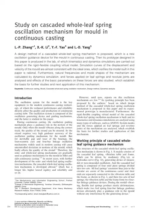
Study on cascaded whole-leaf spring oscillation mechanism for mould in continuous castingL.-P.Zhang*1,X.-K.Li2,Y.-F.Yao2and L.-D.Yang3A design method of a cascaded whole-leaf spring mechanism is proposed,which is a new oscillation guidance device for the mould in continuous casting.Then its prototype designed in this paper is produced in the lab,of which kinematics and dynamics simulations are carried out based on the rigid–flexible coupling virtual model.Simulation curves of the displacement and velocity of the mould are almost consistent with the ideal ones,which verifies the model built in this paper is rational.Furthermore,natural frequencies and mode shapes of the mechanism are calculated by dynamics simulation,and forces applied on leaf springs and revolute joints are analysed and effects of the basic parameters on these forces are also studied,which establish the basis for further studies and next application of this mechanism.Keywords:Continuous casting,Mould,Cascaded whole-leaf spring oscillation mechanism,Design method,Dynamics analysisIntroductionThe oscillation system for the mould is the key equipment to the modern continuous casting technol-ogy,of which the technical performance and reliability directly affect the quality and production of continuous casting slabs.The oscillation system is composed of the oscillation generating device and guiding mechanism, and the latter is studied in this paper.During continuous casting,the oscillation guiding mechanism plays a guidance role in the motion of the mould.Only when the mould vibrates along the correct track,the quality of the strand can be ensured.So the strand requires very high guidance accuracy of the oscillation guiding mechanism for the mould.But for inevitable gap and wear of the bearings,the four-eccentric axes and four-bar linkage oscillation mechanisms widely used in modern casting will cause uncontrolled deviation in motions of the mould,which badly affects the quality of the strand.1Therefore,the semi-and whole-leaf spring mechanisms are gradually used as guidance mechanisms for the mould in billet and slab continuous casting.2,3In recent years,with further development of the semi-and whole-leaf spring oscilla-tion mechanisms,the cascaded whole-leaf spring oscilla-tion mechanism is developed abroad,4which has a longer life,higher lateral rigidity and reliability and so on.However,until now,reports on this oscillation mechanism are few.5,6Its working principle has been proposed by the authors,7based on which design method of the cascaded whole-leaf spring oscillation mechanism is proposed in this paper and its experi-mental prototype is manufactured.Furthermore,the rigid–flexible coupling virtual model of the cascaded whole-leaf spring oscillation mechanism is built and its kinematics and dynamics simulations are analysed using many types of software,such as ANSYS.System modes and the forces applied on leaf springs and revolute joints of the mechanism are analysed,which establish the basis for further studies and application of this mechanism.Working principle of cascaded whole-leaf spring guidance mechanismThe structure of the cascaded whole-leaf spring oscilla-tion mechanism is shown in Fig.1.It mainly consists of the cascaded leaf spring,vibration table and frame, which can be driven by machinery(Fig.1a),or hydraulics servo(Fig.1b),generating device of sinusoi-dal or non-sinusoidal oscillation.And the cascaded leaf spring is composed of four steel plate springs divided into two sets.All leaf springs’extension lines join to the circular arc centre of the continuous caster and their ends are separately connected to the vibration table and the frame,as shown in Fig.2,and then two sets of leaf springs,the vibration table and the frame form two four-bar linkage guidance devices.During the mould vibrat-ing,flexible leaf springs produce elastic deformations, which make two leaf spring four-bar linkage guidance devices alternately play a guidance role in the mould without any interference by the generating device.71The Mechatronics and Information Engineering School,Foshan University,Foshan528000,China2College of Mechanical Engineering,Yanshan University,Qinhuangdao 066004,China3No.2Research Development Department,Xi’an Heavy Machinery Research Institute,Xi’an710032,China*Corresponding author,email zhanglpok@204ß2010Institute of Materials,Minerals and MiningPublished by Maney on behalf of the InstituteReceived14November2008;accepted16September2009DOI10.1179/030192309X12573371383677Ironmaking and Steelmaking2010VOL37NO3Design of cascaded whole-leaf spring oscillation mechanismFrom working principle of the cascaded whole-leaf spring oscillation mechanism,it can be seen that two leaf spring four-bar linkages carry on the guidance to the mould.If design is unreasonable,the motion of the two leaf spring four-bar linkages will interfere during vibration,which will block the mould.Therefore,how to design these two leaf spring four-bar linkages becomes the key problem.Design method of cascaded whole-leaf spring oscillation mechanismAccording to the characters of the cascaded whole-leaf spring mechanism developed from the short-arm four-bar linkage,its design method is proposed as following:(i)based on the design principles of the short-armfour-bar linkage simulating arc,8design two rigid four-bar linkages under the same basic para-meters of the mould by optimum design,which fulfil the requirement for guiding accuracy of the mould simulating arc(ii)for settling interference of the two four-barlinkages,rigid linkages optimised in step (i)are substituted by steel plate springs with elastic deformation and then form two leaf spring four-bar linkages(iii)based on the basic principles of the short-armfour-bar linkage,arrange two leaf spring four-bar linkages according to Fig.2.That is,end-points A 1,C 1and A 2,C 2are fixed on the frame;endpoints B 1,D 1and B 2,D 2are connected to the vibration table of the mould.In this way,two leaf spring four-bar linkages are cascaded,so a cascaded whole-leaf spring mechanism is designed.Calculation exampleCalculations of parameters and guidance accuracy of rigid four-bar linkagesAccording to the geometry relations and the movement relationships of the four-bar linkage guidance devices of the arc caster (see Fig.2),the position of any point on the mould can be calculated during the mould vibration.In this paper,taken the bottom point E on the outer arc of the mould as an example,formulas of the track and the guiding accuracy of point E are deduced,as listed in Table 1,with only one rigid four-bar linkage guiding for the mould.To calculate conveniently,it is assumed that l 1,l 2,l 3and l 4are respectively the lengths of linkages of A 1C 1,A 1B 1,B 1D 1and C 1D 1,and A 2C 2,A 2B 2,B 2D 2and C 2D 2;S is the amplitude of the mould;D Q is the swing angle of the linkage of B 1D 1and B 2D 2under the max displace-ment of the mould downward;R is the caster’s basic radius;R 1and R 2are radius respectively from the arc centre to two endpoints of linkages A 1C 1,B 1D 1,A 2C 2and B 2D 2;H 1and H 2are the heights of both sides to the horizontal centerline of the mould;a is the included angle between OE and the horizontal centreline of the arc caster when the mould is at equilibrium position;h 1,h 2,r 1and r 2are respectively the included angles between linkages of A 1C 1,A 2C 2,B 1D 1,B 2D 2and the horizontal centreline of the caster;D R E is the simulated arc error of the mould.Mathematical model and optimisation of linkagesOscillation parameters of the mould and the installation positions of linkages are the primary designing terms of the guidance mechanism.Taking arc caster for example,outside penalty function optimisation method is adopted in optimum design of the two rigid four-bar linkages.In four-bar linkages design,it is the goal that the trajectory error of the mould meets the requirement for guiding accuracy.So the objective function of the optimisation mathematical model can be written by f(x )~D R E ~OE ’{R ¡0:02(1)According to Table 1,it can be seen that the design optimisation variables are x ~R ,S ,h ,r ,R 1,R 2½ T(2)By experience,geometric dimensions and installation positions of two four-bar linkages must meet the followingconstraints2Layout of cascaded whole-leafspringa mechanic driven;b hydraulics servodriven1Cascaded whole-leaf spring oscillation mechanismZhang et al.Cascaded whole-leaf spring oscillation mechanism for mould in continuous castingIronmaking and Steelmaking 2010VOL37NO320530D ¡R ¡50D 2¡S j j ¡10R 1w 0,h w 0R 2w R 1,r w h 0:91R ¡R 2v R 0:82R ¡R 1¡0:91R(3)where D is the thickness of billet;h and r are included angles between linkages and horizontal centreline of the caster.Based on the objective function (equation (1)),optimisation variables (equation (2))and constraints established in equation (3),optimisation procedure of outside penalty function is compiled by C language and two four-bar linkages are separately optimum designed.Optimisation resultsIn optimisation,it is assumed that the mould is arranged symmetrically about its equilibrium position and its height H 1z H 25900mm;the thickness of the billet D 5150mm;the guiding accuracies of two rigid four-bar linkages D R E 50?02mm.Therefore,the geometrical parameters and the guiding accuracies of the two rigid four-bar linkages are optimum designed (Table 2).By the optimised results,rigid linkages are substituted by leaf springs arranged according to Fig.2;then a cascaded whole-leaf spring mechanism is designed.Experimental prototype of cascaded whole-leaf spring oscillation mechanismBased on the optimised results,the experimental proto-type of the cascaded whole-leaf spring oscillation mechan-ism for the mould is manufactured,as shown in Fig.3,in which leaf spring four-bar linkage A 1C 1B 1D 1is composed of leaf springs 1and 4;and leaf spring four-bar linkage A 2C 2B 2D 2is made up of leaf springs 2and 3.Leaf spring four-bar linkages A 1C 1B 1D 1and A 2C 2B 2D 2are located at both sides of the mould in the vertical direction of casting.And parameters of the prototype are rounded numbers of Table 2and guidance accuracy is calculated after round-ing,as listed in Table 3.Flexible multibody theoryVectors of location,velocity and acceleration of point on flexible bodyBased on the small deformation theory,complicated motion of the flexible body can be decomposed to severalTable 2Optimised results of two rigid four-bar linkagesFour-bar linkage A 1B 1C 1D 1Four-bar linkage A 2B 2C 2D 2R ,mm 5974.695902.74S,mm ¡3.33¡3.19h ,rad 0.050.08r ,rad 0.170.14R 1,mm 5219.795233.23R 2,mm 5490.995505.41D R ,mm20.020.0193Experimental prototypeTable 1Formulas of parameters of two rigid four-bar linkages and error of bottom point E on mould Four-bar linkage A 1B 1C 1D 1Four-bar linkage A 2B 2C 2D 2l 15l 35R 22R 1l 15l 35R 22R 1a 5arcsin(H 2/R )a 5arcsin(H 2/R )D Q 52arcsin(S /2l 1cos r 1)D Q 52arcsin(S /2l 1cos r 1)l 252R 1sin[(r 12h 1)/2]l 252R 1sin[(r 12h 1)/2]l 452R 1sin[(r 12h 1)/2]l 452R 1sin[(r 22h 2)/2]D 1E ~½R 22z R 2{2R 2R cos (r 1{a ) 1=2D 2E ~½R 21z R 2{2R 1R cos (r 2{a ) 1=2C 1E ~½R 22z R 2{2R 2R cos (h 1{a ) 1=2C 2E ~½R 21z R 2{2R 1R cos (h 2{a ) 1=2A 1D 1’~f l 21z l 22z 2l 1l 2sin ½(r 1{h 1)=2z D Q g 1=2A 2D 2’~f l 21z l 22{2l 1l 2sin ½(r 2{h 2)=2{D Q g 1=2c ~arccos ½(l 24z D 1E 2{C 1E 2) (2l 4:D 1E )c ~arccos ½(l 24z D 2E 2{C 2E 2) (2l 4:D 2E )v ~arccos ½(l 24z AD 1’2{l 23).(2l 4:AD 1’) v ~arccos ½(l 24z AD 2’2{l 23).(2l 4:AD 2’)b ~arccos ½(l 21z AD 1’2{l 22).(2l 1:AD 1’)b ~arccos ½(l 21z AD 2’2{l 22).(2l 1:AD 2’)OD 1’~½R 21z l 21z 2R 1l 1cos D Q 1=2OD 2’~½R 22z l 21{2R 2l 1cos D Q 1=2w ~arccos ½(OD 1’2z l 21{R 21).(2OD 1’:l 1)w ~arccos ½(OD 2’2z l 21{R 22).(2OD 2’:l 1)d 5w z c z v z bd 5w z c 2(v z b )OE ’~½D 1E 2z OD 1’2{2D 1E :OD 1’:cos d 1=2OE ’~½D 2E 2z OD ’22{2D 2E :OD 2’:cos d 1=2D R E 5OE 92R D R E 5OE 92RTable 3Parameters of prototypeLeaf spring four-bar linkage A 1B 1C 1D 1Leaf spring four-bar linkage A 2B 2C 2D 2R ,mm 6000.006000.00S ,mm ¡3.00¡3.00h ,u 3.005.00r ,u 10.008.00R 1,mm 5220.005235.00R 2,mm 5490.005505.00D R ,mm20.0160.018Zhang et al.Cascaded whole-leaf spring oscillation mechanism for mould in continuous casting206Ironmaking and Steelmaking 2010VOL37NO3simple motions.So the location vector of any point on the flexible body can be expressed as equation (4).9r p ~r 0z A (s P z u P )(4)where A is the matrix of direction cosine;r P is the vector of point P in the inertial coordinate system;r 0is the vector of the origin of moving coordinate in the inertial coordinate system;s P is the vector of point P in moving coordinate system when the flexible body is undeformed;and u P is the relative deflection of point P expressed by modal coordinates namely u P 5W P q (where W P is the assumed modal matrix and q is the generalised coordinate of deformation).Differentiating equation (4)with respect to time,vectors of velocity and acceleration are calculated:r p ~:r 0z :A (s P z u P )z A W P :q::r p ~::r 0z ::A (s P z u P )z 2:A W P :q z A W P ::q(5)Flexible multibody dynamic equationConsidering the location,direction and mode of point P on the flexible body,the generalised coordinate is selected,as in equation (6).j ~x y z y h w q i (i ~1,:::,M )½ T ~r y q ½ T(6)The motion equation of flexible body is deduced from d L L: {L L z l L y T {Q ~0y ~08><>:(7)where y is restraint equation;l is Lagrange multiplier corresponding to restraint equation;Q is generalised force projected to generalised coordinate j ;L is Lagrange item with L 5T 2W ,and T and W respectively denote kinetic energy and potential energy.The kinetic energy of flexible body is calculated by T ~12:j T M (j ):j(8)where M (j )is mass matrix and M (j )~M tt M tr M tm M T tr M rrM rm M T tm M Trm M mm2435;subscripts t ,r and m respectively denote translation,revolution and modal freedom.The potential energy of flexible body includes the gravitational potential energy and the elastic potential energy,that isW ~W g (j )z 12j T K j(9)where K is generalised stiffness matrix corresponding to modal coordinates and is a constant.Because the mass of the flexible leaf springs is very small comparing to other parts of the oscillation mechanism with cascaded whole-leaf spring,its potential energy could be ignored.So substituting equations (8)and (9)into equation (7),differential equation of motion of the flexible body is written as follows M ::j z :M :j {12L M L j :j T :j z K j z l L y L jjT~Q (10)Kinematics simulation of cascadedwhole-leaf spring oscillation mechanismBased on the flexible multibody theory,the virtual design and then kinematics simulation of the experi-mental prototype of the cascaded whole-leaf spring oscillation mechanism for the mould with non-sinusoi-dal oscillation are carried out using many types of softwares,such as ANSYS,10,11and curves of displace-ment and velocity of the mould are obtained and compared with the ideal ones.Simulation modelBased on the structural characteristic of the cascaded whole-leaf spring oscillation mechanism,it is assumed as follows:(i)the vibration table is symmetric about x –y planeand direction of –y is the casting direction,with the coordinate as shown in Fig.4(ii)leaf springs with elastic deformation are regardedas flexible bodies.Eccentric shaft,connecting rod,vibration table and frame with big stiffness are taken for rigid bodies.So the simulation model of the experimental prototype is built,in which leaf springs 1and 4are composed of two groups of leaf spring four-bar linkage A 1C 1B 1D 1;and leaf springs 2and 3are formed by two groups of leaf spring four-bar linkage A 2C 2B 2D 2(Fig.4).Kinematics simulation and resultsTo simulate the actual non-sinusoidal motion law of themould with the guidance of the cascaded whole-leaf spring mechanism,a non-uniform rotational speed is imposed on the eccentric shaft,as shown in Fig.4,in which the frequency f 52Hz,the deflection ratio of oscillation a 530%and the amplitude of the mould h 53mm.The displacement and velocity curves of the vibration table (i.e.movement curves of the mould)are shown in Fig.5,of which the errors compared with the ideal curves are shown in Fig.6.From Fig.5,it can be seen the virtual vibration table can move along the given non-sinusoidal rule.Although the oscillation waveform of the mould in simulation has error compared with the ideal curves (Fig.6),the maximum errors of the displacement and the velocity are very small (0?0068mm and 0?1287mm s 21respec-tively),and can be ignored.Therefore,it is concluded that the virtual model is rational and can be usedfor4Simulating modelZhang et al.Cascaded whole-leaf spring oscillation mechanism for mould in continuous castingIronmaking and Steelmaking 2010VOL37NO3207further study on the cascaded whole-leaf spring mechanism.Dynamics simulation of oscillation mechanismBased on the dynamic simulation of the cascaded whole-leaf spring oscillation mechanism,system modal and the forces applied on leaf springs and revolute joints are analysed.Modal analysis of oscillation mechanismUsing the instantaneous freezing method of mechan-ism,12modal analysis of the cascaded whole-leaf springguidance mechanism is carried out,from which system modals and natural frequencies are obtained.For the frequency of non-sinusoidal oscillation in continuous casting is not very high,13natural frequencies and mode shapes from the first to the fifth are emphasised in this paper with related information of the modals listed in Table 4.Limited by space,only the first to the third mode shapes are shown in Fig.7.From modal analysis of the mechanism above,it is known that the first and the second natural frequencies are lower and resonance may occur on the mould in continuous casting.14When resonance occurs,the mould will deflect from the correct trajectory,which badly impacts on the quality of strand.So it must be ensured that the working frequency in continuous casting is far from the first and the second natural frequencies of the cascaded whole-leaf spring oscillation mechanism.Analysis of forces applied on leaf springsOwing to the symmetry about the x –y plane,leaf springs in both sides of the cascade whole-leaf spring oscillation mechanism have the same forces and deformations,only the one at the positive axis of z is analysed.For the cascade whole-leaf spring mechanism,leaf spring four-bar linkage A 1C 1B 1D 1and A 2C 2B 2D 2alternately play the guidance role on the mould and forces applied on the leaf spring and their deformations are very complicated.So it is difficult to analyse leaf springs well only by experiments and computer simulation has important significance.In this paper,based on the virtual proto-type technology,dynamics simulation is carried out,by which forces curves of leaf springs are obtained during the mould movement.Furthermore,effects of basic oscillation parameters on these forces are analysed,which establish the basis for further study on the reliability of themechanism.5a displacement and b velocity curves of vibrationtableTable 4Natural frequencies and modes shapes from first to fifth order Modality order Natural frequency,Hz Mode shapes172058Vertical vibration of the vibration table along the casting direction (–y )211.4723Deviated swing of the vibration table about the axis of x 323.7038Vibration of leaf spring 1423.7068524.0872Transverse vibration of the vibration table along the z axis z vibration of leaf spring17a first and b second modal mode shapes of systemZhang et al.Cascaded whole-leaf spring oscillation mechanism for mould in continuous casting208Ironmaking and Steelmaking 2010VOL37NO3Forces applied on leaf springs at different amplitudesTo understand the forces applied on leaf springs under different amplitudes,the motion of the mould with different lengths of the eccentric shaft respectively h 53mm and h 52mm (that is the amplitudes of the mould)are taken for example to simulate in which the deflection ratio of oscillation and the frequency are the same to those in the section on ‘Kinematics simulation and results’.Forces applied along the length direction of leaf springs,for example,are analysed in this paper.Based on the dynamic simulations,forces applied on the ends of leaf springs 1,4and 2,3in a period are obtained as shown in Fig.8.It can be seen that the forces applied on the ends of leaf springs 1and 4are similar and vary at non-sinusoidal rules.When the mould works above its equilibrium position at the first half-period,two leaf springs are compressed on the action of negative forces;when the mould moves under side of its equilibrium position at the second half-period,these two leaf springs are tensioned with positive forces.Furthermore,the values of forces are directly proportional to the distance of the mould departing from its equilibrium position.When the mould moves to its max.displacement,both leaf springs will bear the largest forces.And forces applied on the leaf springs get bigger as the amplitude of mould increases.Forces applied on leaf springs 2and 3vary with the same law,yet opposite to those of leafsprings 1and 4.When the mould is above its equilibrium position at the first half-period,leaf springs 2and 3bear tensile forces;however,at the other half-period,both leaf springs bear pressure.Similarly the values of forces are proportional to the distance of the mould off its equilibrium position and the forces get bigger as the amplitudes of the mould increase.Forces applied on leaf springs at different deflection ratio of oscillationWith the same frequency and amplitude in the section on ‘Kinematics simulation and results’,based on the dynamic simulations at different deflection ratios of oscillation a 1510%,a 2530%,a 3550%,force curves of each leaf spring are obtained,as shown in Fig.9.From Fig.9,it can be seen that with the same frequency and amplitude of oscillation,deflection ratios of the force curves of leaf springs become bigger as the deflection ratio of oscillation enlarges,but the amplitudes of forces applied on every leaf spring keep constant.At the same time there are forces applied in the normal direction of the length of leaf spring,which vary with the same rule to the forces along the length direction.In general,forces applied on leaf springs periodically vary with the same periodicity to the system’s during the mould vibration,the values of which are proportional to the distance of the mould departing from its equilibrium position and get bigger as the amplitude of the mould increases.Deflection ratiosofa leaf spring 1;b leaf spring 4;c leaf spring 2;d leaf spring 38Forces applied on leaf springs at differentamplitudesa leaf spring 1;b leaf spring 2;c leaf spring 3;d leaf spring 49Forces applied on leaf springs at different deflection ratioZhang et al.Cascaded whole-leaf spring oscillation mechanism for mould in continuous castingIronmaking and Steelmaking 2010VOL37NO3209the force curves of leaf springs become bigger with the deflection ratio of oscillation enlarging,but the ampli-tudes of forces of every leaf spring are invariant. Effect of basic oscillatory parameters on joint forcesThe basic oscillatory parameters are often adjusted to meet different technologies in continuous casting,which will affect the joint forces of kinematic pairs and then the dynamic characteristic of the mechanism.Therefore, joint forces are analysed of the cascade whole-leaf spring oscillation mechanism,which shows that amplitude and deflection ratio of oscillation affect joint forces with the similar law to forces applied on leaf springs.Joint forces get bigger as the amplitude of the mould increases and deflection ratios of joint force curves become bigger with increasing the deflection ratio of oscillation;however, the amplitudes of joint forces are constant.Based on analyses above,the cascaded whole-leaf oscillation mechanism can be properly designed for the mould in continuous casting according to practical conditions,which can make the mould vibrate along the correct track with better performance and higher reliability of production.Therefore,the theory basis for application is established.Conclusions1.A design method of the cascaded whole-leaf spring oscillation mechanism is proposed at first.Then a cascaded whole-leaf spring mechanism is designed using the method and its experimental prototype is produced.2.Rigid–flexible coupling full scale model of the prototype of the cascaded whole-leaf spring oscillation mechanism is established;furthermore,its kinematic and dynamic simulations are analysed and compared to those of ideal curves,the results of which verify that the virtual model is rational.3.Working frequency of the system in continuous casting must be kept away from its first and second natural frequencies to avoid resonance.4.The amplitudes of forces applied on leaf springs and revolute joints are only determined by the amplitude of the mould and enlarge with the amplitudes of the mould increasing;and as the deflection ratio of oscillation increases,the deflection of force curves becomes greater.OutlookSuch a system is now being planned for use in industry. References1.Y.G.Yan and X.J.Wang:‘Error analysis and comparison of twotypical mold oscillators’,Heavy Mach.,2006,3,46–48,54.2.in‘800problems of steel-making-continuous casting technology’,214–216;2004,Beijing,Metallurgical Industry Press.3.E.S.Szekeres:‘Overview of mold oscillation in continuouscasting’,Iron Steel Eng.,1996,7,29–37.4.F.Wimmer:‘High speed billet casting:theoretical investigationsand practical experience’,Proc.VAI CCC’96,Linz,Austria,May 1996,VAI,Paper1.TE:‘The cascaded whole-leaf springs oscillation device’,Chinese patent no.ZL02238393.x,February2003.6.R.Ko¨hl,K.Mo¨rwald,J.Po¨ppl and H.Tho¨ne:‘The DYNAFLEXoscillator–a technology breakthrough in billet casting’,Iron Steel, 2001,36,(8),22–25,29.7.L.P.Zhang,X.K.Li,Q.J.Zou and Y.F.Yao:‘Research of theseries whole-leaf spring oscillation mechanism’,Mach.Design Res.Suppl.,2008,24,79–81.8.Z.X.Lei and D.K.Xu:‘Optimum design and analysis of four-barlinkage oscillation mechanism of arc continuous caster’,J.Univ.Iron Steel Beijing,1982,3,80–89.9.Y.Lu:‘Dynamics of flexible multi-body system’,109–165;1996,Beijing,Advanced education Press.10.B.O.Al-Bedoor and A.A.Almusallam:‘Dynamics of flexible-jointmanipulator carrying a payload with rotary inertia’,Mech.Mach.Theory,2000,35,785–820.11.B.O.Al-Bedoor and Y. A.Khulief:‘Finite element dynamicmodeling of a translating and rotating flexible link’,Comput.Methods Appl.Mech.Eng.,1996,131,173–189.12.X.Tang and D.Jin:‘Dynamics of machinery’,169–170;1984,Beijing,Advanced education Press.13.X.K.Li and D.M.Zhang:‘Technology of the mold oscillation incontinuous casting’,20–25;2000,Beijing,Metallurgical Industry Press.14.R.Shao:‘Dynamics of mechanical system’,30–34;2005,Beijing,Mechanical Industry Press.Zhang et al.Cascaded whole-leaf spring oscillation mechanism for mould in continuous casting 210Ironmaking and Steelmaking2010VOL37NO3。
本科毕业设计(本科毕业论文)外文文献及译文文献、资料题目:High-rise Tower Crane designed文献、资料来源:期刊(著作、网络等)文献、资料发表(出版)日期:2000.3.25院(部):机电工程学院专业:机电工程及自动化High-rise Tower Crane designed under Turbulent Winds At present, construction of tower cranes is an important transport operations lifting equipment, tower crane accident the people's livelihood, major hazards, and is currently a large number of tower crane drivers although there are job permits, due to the lack of means to monitor and review the actual work of a serious violation . Strengthen the inspection and assessment is very important. Tower crane tipping the cause of the accident can be divided into two aspects: on the one hand, as a result of the management of tower cranes in place, illegal operation, illegal overloading inclined cable-stayed suspended widespread phenomenon; Second, because of the tower crane safety can not be found in time For example,Took place in the tower crane foundation tilt, micro-cracks appear critical weld, bolts loosening the case of failure to make timely inspection, maintenance, resulting in the continued use of tower cranes in the process of further deterioration of the potential defect, eventually leading to the tower crane tipping. The current limit of tower crane and the black box and can not be found to connect slewing tower and high-strength bolts loosening tightened after the phenomenon is not timely, not tower verticality of the axis line of the lateral-line real-time measurement, do not have to fight the anti-rotation vehicles, lifting bodies plummeted Meng Fang, hook hoists inclined cable is a timely reminder and record of the function, the wind can not be contained in the state of suspended operation to prevent tipping on the necessary tips on site there is a general phenomenon of the overloaded overturning of the whole security risks can not be accurately given a reminder and so on, all of which the lease on the tower crane, use, management problems,Through the use of tower crane anti-tipping monitor to be resolved. Tower crane anti-tipping Monitor is a new high-tech security monitoring equipment, and its principle for the use of machine vision technology and image processing technology to achieve the measurement of the tilt tower, tower crane on the work of state or non-working state of a variety of reasons angle of the tower caused by the critical state to achieve the alarm, prompt drivers to stop illegal operation, a computer chip at the same time on the work of the state of tower crane be recorded. Tower crane at least 1 day overload condition occurs, a maximum number of days to reach 23 overloading, the driver to operate the process of playing the anti-car, stop hanging urgency, such as cable-stayed suspended oblique phenomenon often, after verification and education, to avoid the possible occurrence of fatal accidents. Wind conditions in the anti-tipping is particularly important, tower cranes sometimes connected with the pin hole and pin do not meet design requirements, to connect high-strength bolts are not loose in time after the tightening of the phenomenon, through timely maintenance in time after the tightening of the phenomenon, through timely maintenance and remedial measures to ensure that the safe and reliable construction progress. Reduced lateral line tower vertical axis measuring the number of degrees,Observation tower angle driver to go to work and organize the data once a month to ensure that the lateral body axis vertical line to meet the requirements, do not have to every time and professionals must be completed by Theodolite tower vertical axismeasuring the lateral line, simplified the management link. Data logging function to ensure that responsibility for the accident that the scientific nature to improve the management of data records for the tower crane tower crane life prediction and diagnosis of steel structures intact state data provides a basis for scientific management and proactive prevention of possible accidents, the most important thing is, if the joint use of the black box can be easily and realistically meet the current provisions of the country's related industries. Tower crane safety management at the scene of great importance occurred in the construction process should be to repair damaged steel, usually have to do a good job in the steel tower crane maintenance work and found that damage to steel structures, we must rule out potential causes of accidents, to ensure safety in production carried out smoothly. Tower crane in the building construction has become essential to the construction of mechanical equipment, tower crane at the construction site in the management of safety in production is extremely important. A long time, people in the maintenance of tower crane, only to drive attention to the conservation and electrical equipment at the expense of inspection and repair of steel structures, to bring all kinds of construction accidents.Conclusion: The tower crane anti-tipping trial monitor to eliminate potential causes of accidents to provide accurate and timely information, the tower crane to ensure the smooth development of the leasing business, the decision is correct, and should further strengthen and standardize the use of the environment (including new staff training and development of data processing system, etc.).The first construction cranes were probably invented by the Ancient Greeks and were powered by men or beasts of burden, such as donkeys. These cranes were used for the construction of tall buildings. Larger cranes were later developed, employing the use of human treadwheels, permitting the lifting of heavier weights. In the High Middle Ages, harbour cranes were introduced to load and unload ships and assist with their construction – some were built into stone towers for extra strength and stability. The earliest cranes were constructed from wood, but cast iron and steel took over with the coming of the Industrial Revolution.For many centuries, power was supplied by the physical exertion of men or animals, although hoists in watermills and windmills could be driven by the harnessed natural power. The first 'mechanical' power was provided by steam engines, the earliest steam crane being introduced in the 18th or 19th century, with many remaining in use well into the late 20th century. Modern cranes usually use internal combustion engines or electric motors and hydraulic systems to provide a much greater lifting capability than was previously possible, although manual cranes are still utilised where the provision of power would be uneconomic.Cranes exist in an enormous variety of forms – each tailored to a specific use. Sizes range from the smallest jib cranes, used inside workshops, to the tallest tower cranes,used for constructing high buildings, and the largest floating cranes, used to build oil rigs and salvage sunken ships.This article also covers lifting machines that do not strictly fit the above definition of a crane, but are generally known as cranes, such as stacker cranes and loader cranes.The crane for lifting heavy loads was invented by the Ancient Greeks in the late 6th century BC. The archaeological record shows that no later than c.515 BC distinctive cuttings for both lifting tongs and lewis irons begin to appear on stone blocks of Greek temples. Since these holes point at the use of a lifting device, and since they are to be found either above the center of gravity of the block, or in pairs equidistant from a point over the center of gravity, they are regarded by archaeologists as the positive evidence required for the existence of the crane.The introduction of the winch and pulley hoist soon lead to a widespread replacement of ramps as the main means of vertical motion. For the next two hundred years, Greek building sites witnessed a sharp drop in the weights handled, as the new lifting technique made the use of several smaller stones more practical than of fewer larger ones. In contrast to the archaic period with its tendency to ever-increasing block sizes, Greek temples of the classical age like the Parthenon invariably featured stone blocks weighing less than 15-20 tons. Also, the practice of erecting large monolithic columns was practically abandoned in favour of using several column drums.Although the exact circumstances of the shift from the ramp to the crane technology remain unclear, it has been argued that the volatile social and political conditions of Greece were more suitable to the employment of small, professional construction teams than of large bodies of unskilled labour, making the crane more preferable to the Greek polis than the more labour-intensive ramp which had been the norm in the autocratic societies of Egypt or Assyria.The first unequivocal literary evidence for the existence of the compound pulley system appears in the Mechanical Problems (Mech. 18, 853a32-853b13) attributed to Aristotle (384-322 BC), but perhaps composed at a slightly later date. Around the same time, block sizes at Greek temples began to match their archaic predecessors again, indicating that the more sophisticated compound pulley must have found its way to Greek construction sites by then.During the High Middle Ages, the treadwheel crane was reintroduced on a large scale after the technology had fallen into disuse in western Europe with the demise of the Western Roman Empire. The earliest reference to a treadwheel (magna rota) reappears in archival literature in France about 1225, followed by an illuminated depiction in a manuscript of probably also French origin dating to 1240. In navigation, the earliest uses of harbor cranes are documented for Utrecht in 1244, Antwerp in 1263, Brugge in 1288 and Hamburg in 1291, while in England the treadwheel is not recorded before 1331.Generally, vertical transport could be done more safely and inexpensively by cranes than by customary methods. Typical areas of application were harbors, mines, and, in particular, building sites where the treadwheel crane played a pivotal role in the construction of the lofty Gothic cathedrals. Nevertheless, both archival and pictorial sources of the time suggest that newly introduced machines like treadwheels or wheelbarrows did not completely replace more labor-intensive methods like ladders, hods and handbarrows. Rather, old and new machinery continued to coexist on medieval construction sites and harbors.Apart from treadwheels, medieval depictions also show cranes to be powered manually by windlasses with radiating spokes, cranks and by the 15th century also by windlasses shaped like a ship's wheel. To smooth out irregularities of impulse and get over 'dead-spots' in the lifting process flywheels are known to be in use as early as 1123.The exact process by which the treadwheel crane was reintroduced is not recorded, although its return to construction sites has undoubtedly to be viewed in close connection with the simultaneous rise of Gothic architecture. The reappearance of the treadwheel crane may have resulted from a technological development of the windlass from which the treadwheel structurally and mechanically evolved. Alternatively, the medieval treadwheel may represent a deliberate reinvention of its Roman counterpart drawn from Vitruvius' De architectura which was available in many monastic libraries. Its reintroduction may have been inspired, as well, by the observation of the labor-saving qualities of the waterwheel with which early treadwheels shared many structural similarities.In contrast to modern cranes, medieval cranes and hoists - much like their counterparts in Greece and Rome - were primarily capable of a vertical lift, and not used to move loads for a considerable distance horizontally as well. Accordingly, lifting work was organized at the workplace in a different way than today. In building construction, for example, it is assumed that the crane lifted the stone blocks either from the bottom directly into place, or from a place opposite the centre of the wall from where it could deliver the blocks for two teams working at each end of the wall. Additionally, the crane master who usually gave orders at the treadwheel workers from outside the crane was able to manipulate the movement laterally by a small rope attached to the load. Slewing cranes which allowed a rotation of the load and were thus particularly suited for dockside work appeared as early as 1340. While ashlar blocks were directly lifted by sling, lewis or devil's clamp (German Teufelskralle), other objects were placed before in containers like pallets, baskets, wooden boxes or barrels.It is noteworthy that medieval cranes rarely featured ratchets or brakes to forestall the load from running backward.[25] This curious absence is explained by the high friction force exercised by medieval treadwheels which normally prevented the wheel from accelerating beyond control.目前,塔式起重机是建筑工程进行起重运输作业的重要设备,塔机事故关系国计民生、危害重大,而目前众多的塔机司机虽然有上岗证,由于缺少监督和复核手段,实际工作中违规严重。

Numerical control technology and equipping development trend and countermeasure Equip the engineering level, level of determining the whole national economy of the modernized degree and modernized degree of industry, numerical control technolo gy is it develop new developing new high-tech industry and most advanced industr y to equip (such as information technology and his industry, biotechnology and his industry, aviation, spaceflight, etc. national defense industry) last technology and get ting more basic most equipment. Marx has ever said "the differences of different e conomic times, do not lie in what is produced, and lie in how to produce, produce with some means of labor ". Manufacturing technology and equipping the most ba sic means of production that are that the mankind produced the activity, and nume rical control technology is nowadays advanced manufacturing technology and equips the most central technology. Nowadays the manufacturing industry all around the world adopts numerical control technology extensively, in order to improve manufact uring capacity and level, improve the adaptive capacity and competitive power to th e changeable market of the trends. In addition every industrially developed country in the world also classifies the technology and numerical control equipment of num erical control as the strategic materials of the country, not merely take the great m easure to develop one's own numerical control technology and industry, and imple ment blockading and restrictive policy to our country in view of " high-grade, precisi on and advanced key technology of numerical control " and equipping. In a word, develop the advanced manufacturing technology taking numerical control technology as the core and already become every world developed country and accelerate ec onomic development in a more cost-effective manner, important way to improve the overall national strength and national position.Numerical control technology is the technology controlled to mechanical movement and working course with digital information, integrated products of electromechanics that the numerical control equipment is the new technology represented by numeri cal control technology forms to the manufacture industry of the tradition and infiltrati on of the new developing manufacturing industry, namely the so-called digitization i s equipped, its technological range covers a lot of fields: (1)Mechanical manufacturi ng technology; (2)Information processing, processing, transmission technology; (3)Au tomatic control technology; (4)Servo drive technology; (5)Technology of the sensor;(6)Software engineering ,etc..Development trend of a numerical control technologyThe application of numerical control technology has not only brought the revolutiona ry change to manufacturing industry of the tradition, make the manufacturing industr y become the industrialized symbol , and with the constant development of numeric al control technology and enlargement of the application, the development of some important trades (IT , automobile , light industry , medical treatment ,etc. ) to the n ational economy and the people's livelihood of his plays a more and more importan t role, because the digitization that these trades needed to equip has already been the main trend of modern development. Numerical control technology in the worldat present and equipping the development trend to see, there is the following sever al respect [1- ] in its main research focus.1 A high-speed, high finish machining technology and new trend equippedThe efficiency, quality are subjavanufacturing technology. High-speed, high finish ma chining technology can raise the efficiency greatly , improve the quality and grade of the products, shorten production cycle and improve the market competitive powe r. Japan carries the technological research association first to classify it as one of t he 5 great modern manufacturing technologies for this, learn (CIRP) to confirm it a s the centre in the 21st century and study one of the directions in international pro duction engineering.In the field of car industry, produce one second when beat such as production of 300,000 / vehicle per year, and many variety process it is car that equip key probl em that must be solved one of; In the fields of aviation and aerospace industry, sp are parts of its processing are mostly the thin wall and thin muscle, rigidity is very bad, the material is aluminium or aluminium alloy, only in a situation that cut the speed and cut strength very small high, could process these muscles, walls. Adopt large-scale whole aluminium alloy method that blank " pay empty " make the wing recently, such large-scale parts as the fuselage ,etc. come to substitute a lot of p arts to assemble through numerous rivet , screw and other connection way, make t he intensity , rigidity and dependability of the component improved. All these, to pr ocessing and equipping the demand which has proposed high-speed, high precise and high flexibility.According to EMO2001 exhibition situation, high-speed machining center is it give s peed can reach 80m/min is even high , air transport competent speed can up to 1 00m/min to be about to enter. A lot of automobile factories in the world at present, including Shanghai General Motors Corporation of our country, have already adopt ed and substituted and made the lathe up with the production line part that the hig h-speed machining center makes up. HyperMach lathe of U.S.A. CINCINNATI Com pany enters to nearly biggest 60m/min of speed, it is 100m/min to be fast, the acc eleration reaches 2g, the rotational speed of the main shaft has already reached 6 0 000r/min. Processing a thin wall of plane parts, spend 30min only, and same par t general at a high speed milling machine process and take 3h, the ordinary milling machine is being processed to need 8h; The speed and acceleration of main shaf t of dual main shaft lathes of Germany DMG Company are up to 120000r/mm and 1g.In machining accuracy, the past 10 years, ordinary progression accuse of machinin g accuracy of lathe bring 5μm up to from 10μm already, accurate grades of machi ning center from 3~5μm, rise to 1~1.5μm, and ultraprecision machining accuracy i s it enter nanometer grade to begin already (0.01μm).In dependability, MTBF value of the foreign numerical control device has already re ached above 6 000h, MTBF value of the servo system reaches above 30000h, de monstrate very high dependability .In order to realize high-speed, high finish machining, if the part of function related t o it is electric main shaft, straight line electrical machinery get fast development, the application is expanded further .1.2 Link and process and compound to process the fast development of the lathe i n 5 axesAdopt 5 axles to link the processing of the three-dimensional curved surface part, c an cut with the best geometry form of the cutter , not only highly polished, but als o efficiency improves by a large margin . It is generally acknowledged, the efficienc y of an 5 axle gear beds can equal 2 3 axle gear beds, is it wait for to use the c ubic nitrogen boron the milling cutter of ultra hard material is milled and pared at a high speed while quenching the hard steel part, 5 axles link and process 3 const ant axles to link and process and give play to higher benefit. Because such reason s as complicated that 5 axles link the numerical control system , host computer str ucture that but go over, it is several times higher that its price links the numerical control lathe than 3 axles , in addition the technological degree of difficulty of progr amming is relatively great, have restricted the development of 5 axle gear beds.At present because of electric appearance of main shaft, is it realize 5 axle compl ex main shaft hair structure processed to link greatly simplify to make, it makes de gree of difficulty and reducing by a large margin of the cost, the price disparity of the numerical control system shrinks. So promoted 5 axle gear beds of head of co mplex main shaft and compound to process the development of the lathe (process the lathe including 5).At EMO2001 exhibition, new Japanese 5 of worker machine process lathe adopt co mplex main shaft hair, can realize the processing of 4 vertical planes and processi ng of the wanton angle, make 5 times process and 5 axles are processed and ca n be realized on the same lathe, can also realize the inclined plane and pour the processing of the hole of awls. Germany DMG Company exhibits the DMUVoution series machining center, but put and insert and put processing and 5 axles 5 time s to link and process in once, can be controlled by CNC system or CAD/CAM is c ontrolled directly or indirectly.1.3 Become the main trend of systematic development of contemporary numerical c ontrol intelligently, openly, networkedly.The numerical control equipment in the 21st century will be sure the intelligent syst em, the intelligent content includes all respects in the numerical control system: It i s intelligent in order to pursue the efficiency of processing and process quality, con trol such as the self-adaptation of the processing course, the craft parameter is pro duced automatically; Join the convenient one in order to improve the performance of urging and use intelligently, if feedforward control , adaptive operation , electrical machinery of parameter , discern load select models , since exactly makes etc. a utomatically; The ones that simplified programming , simplified operating aspect are intelligent, for instance intelligent automatic programming , intelligent man-machine interface ,etc.; There are content of intelligence diagnose , intelligent monitoring , di agnosis convenient to be systematic and maintaining ,etc..Produce the existing problem for the industrialization of solving the traditional nume rical control system sealing and numerical control application software. A lot of cou ntries carry on research to the open numerical control system at present, such asNGC of U.S.A. (The Next Generation Work-Station/Machine Control), OSACA of Eu ropean Community (Open System Architecture for Control within Automation System s), OSEC (Open System Environment for Controller) of Japan, ONC (Open Numeri cal Control System) of China, etc.. The numerical control system melts to become the future way of the numerical control system open. The so-called open numerical control system is the development of the numerical control system can be on unifi ed operation platform, face the lathe producer and end user, through changing, incr easing or cutting out the structure target(numerical control function), form the serrati on, and can use users specially conveniently and the technical know-how is integra ted in the control system, realize the open numerical control system of different var iety , different grade fast, form leading brand products with distinct distinction. Syst em structure norm of the open numerical control system at present, communication norm , disposing norm , operation platform , numerical control systematic function storehouse and numerical control systematic function software development ,etc. are the core of present research.The networked numerical control equipment is a new light spot of the fair of the in ternationally famous lathe in the past two years. Meeting production line , manufact ure system , demand for the information integration of manufacturing company netw orkedly greatly of numerical control equipment, realize new manufacture mode such as quick make , fictitious enterprise , basic Entrance that the whole world make t oo. Some domestic and international famous numerical control lathes and systemati c manufacturing companies of numerical control have all introduced relevant new c oncepts and protons of a machine in the past two years, if in EMO2001 exhibition, " Cyber Production Center " that the company exhibits of mountain rugged campst ool gram in Japan (Mazak) (intellectual central production control unit, abbreviated as CPC); The lathe company of Japanese big Wei (Okuma ) exhibits " IT plaza " (the information technology square , is abbreviated as IT square ); Open Manufactu ring Environment that the company exhibits of German Siemens (Siemens ) (open t he manufacturing environment, abbreviated as OME),etc., have reflected numerical control machine tooling to the development trend of networked direction.1.4 Pay attention to the new technical standard, normal setting-up1.4.1 Design the norm of developing about the numerical control systemAs noted previously, there are better common ability, flexibility, adaptability, expandi ng in the open numerical control system, such countries as U.S.A. ,European Com munity and Japan ,etc. implement the strategic development plan one after another , carry on the research and formulation of the systematic norm (OMAC , OSACA , OSEC ) of numerical control of the open system structure, 3 biggest economies in the world have carried on the formulation that nearly the same science planned a nd standardized in a short time, have indicated a new arrival of period of change of numerical control technology. Our country started the research and formulation of standardizing the frame of ONC numerical control system of China too in 2000. 1.4.2 About the numerical control standardThe numerical control standard is a kind of trend of information-based development of manufacturing industry. Information exchange among 50 years after numerical control technology was born was all because of ISO6983 standard, namely adopt G, M code describes how processes, its essential characteristic faces the processing course, obviously, he can't meet high-speed development of modern numerical cont rol technology's needs more and more already. For this reason, studying and maki ng a kind of new CNC system standard ISO14649 (STEP-NC) in the world, its pur pose is to offer a kind of neutral mechanism not depending on the concrete syste m, can describe the unified data model in cycle of whole life of the products, thus realize the whole manufacture process, standardization of and even each industrial field product information.The appearance of STEP-NC may be a revolution of the technological field of the numerical control, on the development and even the whole manufacturing industry of numerical control technology, will exert a far-reaching influence. First of all, STE P-NC puts forward a kind of brand-new manufacture idea, in the traditional manufa cture idea, NC processes the procedures to all concentrate on individual computer. Under the new standard, NC procedure can be dispersed on Internet, this is exac tly a direction of open , networked development of numerical control technology. Se condly, STEP-NC numerical control system can also reduce and process the drawi ng (about 75%), process the procedure to work out the time (about 35%) and proc ess the time (about 50%) greatly.At present, American-European countries pay much attention to the research of ST EP-NC, Europe initiates IMS plan (1999.1.1-2001.12.3) of STEP-NC. 20 CAD/CAM/ CAPP/CNC users, manufacturers and academic organizations from Europe and Jap an participated in this plan. STEP Tools Company of U.S.A. is a developer of the data interchange software of manufacturing industry in the global range, he has alr eady developed the super model (Super Model ) which accuses of information exc hange of machine tooling by counting, its goal is to describe all processing courses with the unified norm. Such new data interchange form has already been verified i n allocating the SIEMENS, FIDIA and European OSACA-NC numerical control at pr esent.2 pairs of basic estimations of technology and industry development of numerical c ontrol of our countryThe technology of numerical control of our country started in 1958, the developmen t course in the past 50 years can roughly be divided into 3 stages: The first stage is from 1958 to 1979, namely closed developing stage. In this stages, because te chnology of foreign countries blockade and basic restriction of terms of our country, the development of numerical control technology is comparatively slow. During "Six th Five-Year Plan Period" , " the Seventh Five-Year Plan Period " of the country in second stage and earlier stage in " the Eighth Five-Year Plan Period ", namely in troduce technology, digest and assimilate, the stage of establishing the system of p roduction domesticization arisesing tentatively. At this stage , because of reform an d opening-up and national attention , and study the improvement of the developme nt environment and international environment, research , development and all makin g considerable progress in production domesticization of the products of the technol ogy of numerical control of our country. The third stage is and during the "Ninth Five-Year Plan Period" on the later stage in "the Eighth Five-Year Plan Period" of th e country, namely implement the research of industrialization, enter market competit ion stage. At this stage, made substantive progress in industrialization of the dome stic numerical control equipment of our country. In latter stage for "the Ninth Five-Y ear Plan ", the domestic occupation rate of market of the domestic numerical contr ol lathe is up to 50%, it is up to 10% too to mix the domestic numerical control s ystem (popular).Make a general survey of the development course in the past 50 years of technolo gy of numerical control of our country, especially through tackling key problems of4 Five-Year Plans, all in all has made following achievements.a. Have established the foundation of the technical development of numerical contr ol, has mastered modern numerical control technology basically. Our country has al ready, the numerical control host computer, basic technology of special plane and f ittings grasped and driven from the numerical control system and survey basically n ow, among them most technology have already possessed and commercialized the foundation developed, some technology has already, industrialization commercialize d.b. Have formed the industrial base of numerical control tentatively. In tackling key problems the foundation that the achievement and some technology commercialize, set up the systematic factories of numerical control with production capacity in batc hes such as numerical control in Central China, numerical control of the spaceflight etc.. Electrical machinery plant of Lanzhou, such factory and the first machine tool plant of Beijing , the first machine tool plant of Jinan ,etc. several numerical contr ol host computer factories of a batch of servo systems and servo electrical machin eries as the numerical control in Central China, etc.. These factories have formed t he numerical control industrial base of our country basically.c. Have set up a numerical control research, development, managerial talent's basic team.Though has made considerable progress in research and development and industri alization of numerical control technology, but we will realize soberly, the research a nd development of the technology of advanced numerical control of our country, es pecially there is greater disparity in current situation and current demand of our co untry of engineering level in industrialization. Though very fast from watching the d evelopment of our country vertically, have disparity horizontally more than (compare foreign countries with) not merely engineering level, there is disparity too in develo pment speed in some aspects, namely the engineering level disparity between som e high-grade , precision and advanced numerical control equipment has the tenden cy to expand . Watch from world, estimate roughly as follows about the engineerin g level of numerical control of our country and industrialization level.a. On the engineering level, in probably backward 10-1 years with the advanced le vel in foreign countries, it is bigger in high-quality precision and sophisticated techn ology.b. On the industrialization level, the occupation rate of market is low, the variety co verage rate is little, have not formed the large-scale production yet; The specializedlevel of production of function part and ability of forming a complete set are relati vely low; Appearance quality is relatively poor; Dependability is not high, the comm ercialized degree is insufficient; One's own brand effect that the domestic numerical control system has not been set up yet, users have insufficient confidence.c. On the ability of sustainable development, research and development of numeric al control technology, project ability is relatively weak to the competition; It is not st rong that the technological application of numerical control expands dynamics; Rese arch, formulation that relevant standards are normal lag behind.It is analyzed that the main reason for having above-mentioned disparity has the fo llowing several respect.a. Realize the respect. Know to industry's process arduousness , complexity and lo ng-term characteristic of domestic numerical control insufficiently; It is difficult to un derestimate to add strangling, system, etc. to the unstandard, foreign blockade of t he market; It is not enough to analyse to the technological application level and ab ility of numerical control of our country.b. System. Pay close attention to numerical control industrialization many in the iss ue, consider numerical control industrialization little in the issue synthetically in term s of the systematic one, industry chain in terms of technology; Have not set up rel ated system, perfect training , service network of intact high quality ,etc. and suppo rted the system.c. Mechanism. It causes the brain drain, restraining technology and technological ro ute from innovating again, products innovation that the bad machine is made, and has restricted the effective implementation of planning, has often planned the ideal, implement the difficulty.d. Technology. The autonomous innovation in technology of enterprises is indifferen t; the project of key technology is indifferent. The standard of the lathe lags behind, the level is relatively low, it is not enough for new standard of the numerical contr ol system to study.3 pairs of strategic thinking of technology and industrialized development of numeri cal control of our country3.1 Strategic considerationOur country make big country, industry is it is it accept front instead of transformati on of back end to try one's best to want in shifting in world, namely should master and make key technology advanced, otherwise in a new round of international ind ustrial structure adjustment, the manufacturing industry of our country will step forw ard and " leave the core spaces ". We regard resource, environment , market as t he cost, it is only an international " machining center " in the new economic patter n of the world to exchange the possibility got and " assemble the centre ", but not master the position of the manufacturing center of key technology , will so influen ce the development process of the modern manufacturing industry of our country s eriously.We should stand in the height of national security strategy paying attention to num erical control technology and industry's question , at first seen from social safety, b ecause manufacturing industry whether our country obtain employment most populous trade, the development of manufacturing industry not only can improve the peop le's living standard but also can alleviate the pressure of employment of our countr y , ensure the stability of the society; Secondly seen from national defense security, the western developed country has classified all the high-grade , precision and ad vanced numerical control products as the strategic materials of the country, realizin g the embargo and restriction to our country, " Toshiba incident " and " Cox Repor t " is the best illustration.3.2 Development tacticsProceed from the angles of the fundamental realities of the country of our country, regard the strategic demand of the country and market demand of national econo my as the direction, regard improving our country and making the comprehensive c ompetitive power of equipping industry and industrialization level as the goal, use t he systematic method , be able to choose to make key technology upgraded in de velopment of equipping industry and support technology supporting the development of industrialization in our country in initial stage of 21st century in leading factor, t he ability to supply the necessary technology realizes making the jump developmen t of the equipping industry as the content of research and development . Emphasize market demand is a direction, namely take terminal products of numeric al control as the core, with the complete machine (Such as the numerical control l athe having a large capacity and a wide range, milling machine, high speed high p recise high-performance numerical control lathe, digitized machinery of model, key i ndustry key equipment, etc.) drive the development of the numerical control industr y. Solve the numerical control system and relevant functions part especially The de pendability that (digitized servo system and electrical machinery, high speed electric main shaft system and new-enclosure that equip, etc.) and production scale questi on. There are no products that scale will not have high dependability; Will not have cheap and products rich in the competitiveness without scale; Certainly, it is diffic ult to have day holding up one's head finally that there is no scale Chinese numeri cal control equipment.In equiping researching and developing high-grade , precision and advancedly , sho uld emphasize the production, learning and research and close combination of the end user, regard " drawing, using, selling " as the goal, tackle key problems accor ding to the national will, in order to solve the needing badly of the country. Numerical control technology, emphasized innovation, put emphasis on researching and developing the technology and products with independent intellectual property ri ght before the competition, establish the foundation for the industry of numerical co ntrol of our country, sustainable development of equipment manufacture and even t he whole manufacturing industry.数控技术和装备发展趋势及对策装备工业的技术水平和现代化程度决定着整个国民经济的水平和现代化程度,数控技术及装备是发展新兴高新技术产业和尖端工业(如信息技术及其产业、生物技术及其产业、航空、航天等国防工业产业)的使能技术和最基本的装备。
毕业设计论文外文资料原文及译文学院:机电工程学院专业:机械设计制造及其自动化班级:学号:姓名:Mechanical engineering1.The porfile of mechanical engineeringEngingeering is a branch of mechanical engineerig,it studies mechanical and power generation especially power and movement.2.The history of mechanical engineering18th century later periods,the steam engine invention has provided a main power fountainhead for the industrial revolution,enormously impelled each kind of mechznical biting.Thus,an important branch of a new Engineering – separated from the civil engineering tools and machines on the branch-developed together with Birmingham and the establishment of the Associantion of Mechanical Engineers in 1847 had been officially recognized.The mechanical engineering already mainly used in by trial and error method mechanic application technological development into professional engineer the scientific method of which in the research,the design and the realm of production used .From the most broad perspective,the demend continuously to enhance the efficiencey of mechanical engineers improve the quality ofwork,and asked him to accept the history of the high degree of education and training.Machine operation to stress not only economic but also infrastructure costs to an absolute minimun.3.The field of mechanical engineeringThe commodity machinery development in the develop country,in the high level material life very great degree is decided each kind of which can realize in the mechanical engineering.Mechanical engineers unceasingly will invent the machine next life to produce the commodity,unceasingly will develop the accuracy and the complexity more and more high machine tools produces the machine.The main clues of the mechanical development is:In order to enhance the excellent in quality and reasonable in price produce to increase the precision as well as to reduce the production cost.This three requirements promoted the complex control system development.The most successful machine manufacture is its machine and the control system close fusion,whether such control system is essentially mechanical or electronic.The modernized car engin production transmission line(conveyer belt)is a series of complex productions craft mechanizationvery good example.The people are in the process of development in order to enable further automation of the production machinery ,the use of a computer to store and handle large volumes of data,the data is a multifunctional machine tools necessary for the production of spare parts.One of the objectives is to fully automated production workshop,three rotation,but only one officer per day to operate.The development of production for mechanical machinery must have adequate power supply.Steam engine first provided the heat to generate power using practical methods in the old human,wind and hydropower,an increase of engin .New mechanical engineering industry is one of the challenges faced by the initial increase thermal effciency and power,which is as big steam turbine and the development of joint steam boilers basically achieved.20th century,turbine generators to provide impetus has been sustained and rapid growth,while thermal efficiency is steady growth,and large power plants per kW capital consumption is also declining.Finally,mechanical engineers have nuclear energy.This requires the application of nuclear energy particularly high reliability and security,which requires solving many new rge power plants and the nuclear power plant control systems have become highly complex electroonics,fluid,electricity,water and mechanical parts networks All in all areas related to the mechanical engineers.Small internal combustion engine,both to the type (petrol and diesel machines)or rotary-type(gas turbines and Mong Kerr machine),as well as their broad application in the field of transport should also due to mechanical enginerrs.Throughout the transport,both in the air and space,or in the terrestrial and marine,mechanial engineers created a variety of equipment and power devices to their increasing cooperation with electrical engineers,especially in the development of appropration control systems.Mechanical engineers in the development of military weapons technology and civil war ,needs a similar,though its purpose is to enhance rather than destroy their productivity.However.War needs a lot of resources to make the area of techonlogy,many have a far-reaching development in peacetime efficiency.Jet aircraft and nuclear reactors are well known examples.The Biological engineering,mechanical engineering biotechnology is a relatively new and different areas,it provides for the replacement of the machine or increase thebody functions as well as for medical equipment.Artficial limbs have been developed and have such a strong movement and touch response function of the human body.In the development of artificial organ transplant is rapid,complex cardiac machines and similar equipment to enable increasingly complex surgery,and injuries and ill patients life functions can be sustained.Some enviromental control mechanical engineers through the initial efforts to drainage or irrigation pumping to the land and to mine and ventilation to control the human environment.Modern refrigeration and air-conditioning plant commonaly used reverse heat engine,where the heat from the engine from cold places to more external heat.Many mechanical engineering products,as well as other leading technology development city have side effects on the environment,producing noise,water and air pollution caused,destroyed land and landscape.Improve productivity and diver too fast in the commodity,that the renewable naturalforces keep pace.For mechanical engineers and others,environmental control is rapidly developing area,which includes a possible development and production of small quantities of pollutants machine sequnce,and the development of new equipment and teachnology has been to reduce and eliminate pollution.4.The role of mechanical engineeringThere are four generic mechanical engineers in common to the above all domains function.The 1st function is the understanding and the research mechanical science foundation.It includes the power and movement of the relationship dynamics For example,in the vibration and movement of the relationship;Automatic control;Study of the various forms of heart,energy,power relations between the thermodynamic;Fluidflows; Heat transfer; Lubricant;And material properties.The 2nd function will be conducts the research,the desing and the development,this function in turn attempts to carry on the essential change to satisfy current and the future needs.This not only calls for a clear understanding of mechanical science,and have to breakdown into basic elements of a complex system capacity.But also the need for synthetic and innovative inventions.The 3rd function is produces the product and the power,include plan,operation and maintenance.Its goal lies in the maintenance eitherenhances the enterprise or the organization longer-tern and survivabilaty prestige at the same time,produces the greatest value by the least investments and the consumption.The 4th function is mechanical engineer’s coordinated function,including the management,the consultation,as well as carries on the market marking in certain situation.In all these function,one kind unceasingly to use the science for a long time the method,but is not traditional or the intuition method tendency,this is a mechanical engineering skill aspect which unceasingly grows.These new rationalization means typical names include:The operations research,the engineering economics,the logical law problem analysis(is called PABLA) However,creativity is not rationalization.As in other areas,in mechanical engineering,to take unexpected and important way to bring about a new capacity,still has a personal,marked characteristice.5.The design of mechanical engineeringThe design of mechanical is the design has the mechanical property the thing or the system,such as:the instrument and the measuring appliance in very many situations,the machine design must use the knowledge of discipline the and so on mathematics,materials science and mechanics.Mechanical engineering desgin includeing all mechanical desgin,but it was a study,because it also includes all the branches of mechsnical engineering,such as thermodynamics all hydrodynamics in the basic disciplines needed,in the mechanical engineering design of the initial stude or mechanical design.Design stages.The entire desgin process from start to finish,in the process,a demand that is designed for it and decided to do the start.After a lot of repetition,the final meet this demand by the end of the design procees and the plan.Design considerations.Sometimes in a system is to decide which parts needs intensity parts of geometric shapesand size an important factor in this context that we must consider that the intensity is an important factor in the design.When we use expression design considerations,we design parts that may affect the entire system design features.In the circumstances specified in the design,usually for a series of such functions must be taken into account.Howeever,to correct purposes,we should recognize that,in many cases thedesign of important design considerations are not calculated or test can determine the components or systems.Especially students,wheen in need to make important decisions in the design and conduct of any operation that can not be the case,they are often confused.These are not special,they occur every day,imagine,for example,a medical laboratory in the mechanical design,from marketing perspective,people have high expectations from the strength and relevance of impression.Thick,and heavy parts installed together:to produce a solid impression machines.And sometimes machinery and spare parts from the design style is the point and not the other point of view.Our purpose is to make those you do not be misled to believe that every design decision will needreasonable mathematical methods.Manufacturing refers to the raw meterials into finished products in the enterprise.Create three distinct phases.They are:input,processing exprot.The first phase includes the production of all products in line with market needs essential.First there must be the demand for the product,the necessary materials,while also needs such as energy,time,human knowledge and technology resourcess .Finall,the need for funds to obtain all the other resources. Lose one stage after the second phase of the resources of the processes to be distributed.Processing of raw materials into finished products of these processes.To complete the design,based on the design,and then develop plans.Plan implemented through various production processes.Management of resources and processes to ensure efficiency and productivity.For example,we must carefully manage resources to ensure proper use of funds.Finally,people are talking about the product market was cast.Stage is the final stage of exporting finished or stage.Once finished just purchased,it must be delivered to the users.According to product performance,installation and may have to conduct further debugging in addition,some products,especially those very complex products User training is necessary.6.The processes of materials and maunfacturingHere said engineering materials into two main categories:metals and non-ferrous,high-performance alloys and power metals.Non-metallic futher divided into plastice,synthetic rubber,composite materials and ceramics.It said the productionproccess is divided into several major process,includingshape,forging,casting/ founding,heat treatment,fixed/connections ,measurement/ quality control and materal cutting.These processes can be further divide into each other’s craft.Various stages of the development of the manufacturing industry Over the years,the manufacturing process has four distinct stages of development, despite the overlap.These stages are:The first phase is artisanal,the second Phase is mechanization.The third phase is automation the forth Phase is integrated.When mankind initial processing of raw materials into finished products will be,they use manual processes.Each with their hands and what are the tools manuslly produced.This is totally integrated production take shape.A person needs indentification,collection materials,the design of a product to meet that demand,the production of such products and use it.From beginning to end,everything is focused on doing the work of the human ter in the industrial revolution introduced mechanized production process,people began to use machines to complete the work accomplished previously manual. This led to the specialization.Specialization in turn reduce the manufacture of integrated factors.In this stage of development,manufacturing workers can see their production as a whole represent a specific piece of the part of the production process.One can not say that their work is how to cope with the entire production process,or how they were loaded onto a production of parts finished.Development of manufacting processes is the next phase of the selection process automation.This is a computer-controlled machinery and processes.At this stage,automation island began to emerge in the workshop lane.Each island represents a clear production process or a group of processes.Although these automated isolated island within the island did raise the productivity of indivdual processes,but the overall productivity are often not change.This is because the island is not caught in other automated production process middle,but not synchronous with them .The ultimate result is the efficient working fast parked through automated processes,but is part of the stagnation in wages down,causing bottlenecks.To better understand this problem,you can imagine the traffic in the peak driving a red light from the red Service Department to the next scene. Occasionally you will find a lot less cars,more than being slow-moving vehicles,but the results can be found by thenext red light Brance.In short you real effect was to accelerate the speed of a red Department obstruction offset.If you and other drivers can change your speed and red light simultaneously.Will advance faster.Then,all cars will be consistent,sommth operation,the final everyone forward faster.In the workshop where the demand for stable synchronization of streamlined production,and promoted integration of manufacturing development.This is a still evolving technology.Fully integrated in the circumstances,is a computer-controllrd machinery and processing.integrated is completed through computer.For example in the preceding paragraph simulation problems,the computer will allow all road vehicles compatible with the change in red.So that everyone can steady traffic.Scientific analysis of movement,timing and mechanics of the disciplines is that it is composed of two pater:statics and dynamics.Statics analyzed static system that is in the system,the time is not taken into account,research and analysis over time and dynamics of the system change.Dynameics from the two componets.Euler in 1775 will be the first time two different branches: Rigid body movement studies can conveniently divided into two parts:geometric and mechanics.The first part is without taking into account the reasons for the downward movement study rigid body from a designated location to another point of the movement,and must use the formula to reflect the actual,the formula would determine the rigid body every point position. Therefore,this study only on the geometry and,more specifically,on the entities from excision.Obviously,the first part of the school and was part of a mechanical separation from the principles of dynamics to study movement,which is more than the two parts together into a lot easier.Dynamics of the two parts are subsequently divided into two separate disciplines,kinematic and dynamics,a study of movement and the movement strength.Therefore,the primary issue is the design of mechanical systems understand its kinematic.Kinematic studies movement,rather than a study of its impact.In a more precise kinematic studies position,displacement,rotation, speed,velocity and acceleration of disciplines,for esample,or planets orbiting research campaing is a paradigm.In the above quotation content should be pay attention that the content of the Euler dynamics into kinematic and rigid body dynamics is based on the assumptionthat they are based on research.In this very important basis to allow for the treatment of two separate disciplines.For soft body,soft body shape and even their own soft objects in the campaign depends on the role of power in their possession.In such cases,should also study the power and movement,and therefore to a large extent the analysis of the increased complexity.Fortunately, despite the real machine parts may be involved are more or less the design of machines,usually with heavy material designed to bend down to the lowest parts.Therefore,when the kinematic analysis of the performance of machines,it is often assumed that bend is negligible,spare parts are hard,but when the load is known,in the end analysis engine,re-engineering parts to confirm this assnmption.机械工程1.机械工程简介机械工程是工程学的一个分支,它研究机械和动力的产,尤其是力和动力。
文献翻译英文原文:NOVEL METHOD OF REALIZING THE OPTIMAL TRANSMISSION OF THE CRANK-AND-ROCKER MECHANISM DESIGN Abstract: A novel method of realizing the optimal transmission of the crank-and-rocker mechanism is presented. The optimal combination design is made by finding the related optimal transmission parameters. The diagram of the optimal transmission is drawn. In the diagram, the relation among minimum transmission angle, the coefficient of travel speed variation, the oscillating angle of the rocker and the length of the bars is shown, concisely, conveniently and directly. The method possesses the main characteristic. That it is to achieve the optimal transmission parameters under the transmission angle by directly choosing in the diagram, according to the given requirements. The characteristics of the mechanical transmission can be improved to gain the optimal transmission effect by the method. Especially, the method is simple and convenient in practical use.Keywords:Crank-and-rocker mechanism, Optimal transmission angle, Coefficient of travel speed variationINTRODUCTIONBy conventional method of the crank-and-rocker design, it is very difficult to realize the optimal combination between the various parameters for optimal transmission. The figure-table design method introduced in this paper can help achieve this goal. With given conditions, we can, by only consulting the designing figures and tables, get the relations between every parameter and another of the designed crank-and-rocker mechanism. Thus the optimal transmission can be realized.The concerned designing theory and method, as well as the real cases of its application will be introduced later respectively.1ESTABLISHMENT OF DIAGRAM FOR OPTIMAL TRANSMISSION DESIGNIt is always one of the most important indexes that designers pursue to improve the efficiency and property of the transmission. The crank-and-rocker mechanism is widely used in the mechanical transmission. How to improve work ability and reduce unnecessary power losses is directly related to the coefficient of travel speed variation, the oscillating angle of the rocker and the ratio of the crank and rocker. The reasonable combination of these parameters takes an important effect on the efficiency and property of the mechanism, which mainly indicates in the evaluation of the minimum transmission angle.The aim realizing the optimal transmission of the mechanism is how to find themaximum of the minimum transmission angle. The design parameters are reasonably combined by the method of lessening constraints gradually and optimizing separately. Consequently, the complete constraint field realizing the optimal transmission is established.The following steps are taken in the usual design method. Firstly, the initial values of the length of rocker 3l and the oscillating angle of rocker ϕ are given. Then the value of the coefficient of travel speed variation K is chosen in the permitted range. Meanwhile, the coordinate of the fixed hinge of crank A possibly realized is calculated corresponding to value K .1.1 Length of bars of crank and rocker mechanismAs shown in Fig.1, left arc G C 2 is the permitted field of point A . Thecoordinates of point A are chosen by small step from point 2C to point G .The coordinates of point A are 02h y y c A -= (1)22A A y R x -= (2)where 0h , the step, is increased by small increment within range(0,H ). If the smaller the chosen step is, the higher the computational precision will be. R is the radius of the design circle. d is the distance from 2C to G .2cos )2cos(22cos 33ϕθϕϕ⎥⎦⎤⎢⎣⎡--+=l R l d (3) Calculating the length of arc 1AC and 2AC , the length of the bars of themechanism corresponding to point A is obtained [1,2].1.2 Minimum transmission angle min γMinimum transmission angle min γ(see Fig.2) is determined by the equations [3]322142322min 2)(cos l l l l l l --+=γ (4) 322142322max 2)(cos l l l l l l +-+=γ (5) max min180γγ-︒=' (6) where 1l ——Length of crank(mm)2l ——Length of connecting bar(mm)3l ——Length of rocker(mm)4l ——Length of machine frame(mm)Firstly, we choose minimum comparing min γ with minγ'. And then we record all values of min γ greater than or equal to ︒40 and choose the maximum of them.Secondly, we find the maximum of min γ corresponding to any oscillating angle ϕ which is chosen by small step in the permitted range (maximum of min γ is different oscillating angle ϕ and the coefficient of travel speed variation K ).Finally, we change the length of rockerl by small step similarly. Thus we3γcorresponding to the different length of bars, may obtain the maximum ofmindifferent oscillating angle ϕand the coefficient of travel speed variation K.Fig.3 is accomplished from Table for the purpose of diagram design.It is worth pointing out that whatever the length of rocker 3l is evaluated, the location that the maximum of min γ arises is only related to the ratio of the length of rocker and the length of machine frame 3l /4l , while independent of 3l .2 DESIGN METHOD2.1 Realizing the optimal transmission design given the coefficient of travelspeed variation and the maximum oscillating angle of the rockerThe design procedure is as follows.(1) According to given K and ϕ, taken account to the formula the extreme included angle θ is found. The corresponding ratio of the length of bars 3l /4l is obtained consulting Fig.3.︒⨯+-=18011K K θ (7) (2) Choose the length of rocker 3l according to the work requirement, the length of the machine frame is obtained from the ratio 3l /4l .(3) Choose the centre of fixed hinge D as the vertex arbitrarily, and plot an isosceles triangle, the side of which is equal to the length of rocker 3l (see Fig.4), andϕ=∠21DC C . Then plot 212C C M C ⊥, draw N C 1, and make angleθ-︒=∠9012N C C . Thus the point of intersection of M C 2 and N C 1 is gained. Finally, draw the circumcircle of triangle 21C PC ∆.(4) Plot an arc with point D as the centre of the circle, 4l as the radius. The arc intersections arc G C 2 at point A . Point A is just the centre of the fixed hinge of the crank.Therefore, from the length of the crank2/)(211AC AC l -= (8)and the length of the connecting bar112l AC l -= (9)we will obtain the crank and rocker mechanism consisted of 1l , 2l , 3l , and 4l .Thus the optimal transmission property is realized under given conditions.2.2 Realizing the optimal transmission design given the length of the rocker (or the length of the machine frame) and the coefficient of travel speed variationWe take the following steps.(1) The appropriate ratio of the bars 3l /4l can be chosen according to given K . Furthermore, we find the length of machine frame 4l (the length of rocker 3l ).(2) The corresponding oscillating angle of the rocker can be obtained consulting Fig.3. And we calculate the extreme included angle θ.Then repeat (3) and (4) in section 2.13 DESIGN EXAMPLEThe known conditions are that the coefficient of travel speed variation1818.1=K and maximum oscillating angle ︒=40ϕ. The crankandrockermechanism realizing the optimal transmission is designed by the diagram solution method presented above.First, with Eq.(7), we can calculate the extreme included angle ︒=15θ. Then, we find 93.0/43=l l consulting Fig.3 according to the values of θ and ϕ.If evaluate 503=l mm, then we will obtain 76.5393.0/504==l mm. Next, draw sketch(omitted).As result, the length of bars is 161=l mm,462=l mm,503=l mm,76.534=l mm.The minimum transmission angle is︒=--+=3698.462)(arccos 322142322min l l l l l l γ The results obtained by computer are 2227.161=l mm, 5093.442=l mm, 0000.503=l mm, 8986.534=l mm.Provided that the figure design is carried under the condition of the Auto CAD circumstances, very precise design results can be achieved.4 CONCLUSIONSA novel approach of diagram solution can realize the optimal transmission of the crank-and-rocker mechanism. The method is simple and convenient in the practical use. In conventional design of mechanism, taking 0.1 mm as the value of effective the precision of the component sizes will be enough.译文:认识曲柄摇臂机构设计的最优传动方法摘要:一种曲柄摇臂机构设计的最优传动的方法被提出。
Machine design theoryThe machine design is through designs the new product or improves the old product to meet the human need the application technical science. It involves the project technology each domain, mainly studies the product the size, the shape and the detailed structure basic idea, but also must study the product the personnel which in aspect the and so on manufacture, sale and use question.Carries on each kind of machine design work to be usually called designs the personnel or machine design engineer. The machine design is a creative work. Project engineer not only must have the creativity in the work, but also must in aspect and so on mechanical drawing, kinematics, engineerig material, materials mechanics and machine manufacture technology has the deep elementary knowledge.If front sues, the machine design goal is the production can meet the human need the product. The invention, the discovery and technical knowledge itself certainly not necessarily can bring the advantage to the humanity, only has when they are applied can produce on the product the benefit. Thus, should realize to carries on before the design in a specific product, must first determine whether the people do need this kind of productMust regard as the machine design is the machine design personnel carries on using creative ability the product design, the system analysis and a formulation product manufacture technology good opportunity. Grasps the project elementary knowledge to have to memorize some data and the formula is more important than. The merely service data and the formula is insufficient to the completely decision which makes in a good design needs. On the other hand, should be earnest precisely carries on all operations. For example, even if places wrong a decimal point position, also can cause the correct design to turn wrongly.A good design personnel should dare to propose the new idea, moreover is willing to undertake the certain risk, when the new method is not suitable, use original method. Therefore, designs the personnel to have to have to have the patience, because spendsthe time and the endeavor certainly cannot guarantee brings successfully. A brand-new design, the request screen abandons obsoletely many, knows very well the method for the people. Because many person of conservativeness, does this certainly is not an easy matter. A mechanical designer should unceasingly explore the improvement existing product the method, should earnestly choose originally, the process confirmation principle of design in this process, with has not unified it after the confirmation new idea.Newly designs itself can have the question occurrence which many flaws and has not been able to expect, only has after these flaws and the question are solved, can manifest new goods come into the market the product superiority. Therefore, a performance superior product is born at the same time, also is following a higher risk. Should emphasize, if designs itself does not request to use the brand-new method, is not unnecessary merely for the goal which transform to use the new method.In the design preliminary stage, should allow to design the personnel fully to display the creativity, not each kind of restraint. Even if has had many impractical ideas, also can in the design early time, namely in front of the plan blueprint is corrected. Only then, only then does not send to stops up the innovation the mentality. Usually, must propose several sets of design proposals, then perform the comparison. Has the possibility very much in the plan which finally designated, has used certain not in plan some ideas which accepts.How does the psychologist frequently discuss causes the machine which the people adapts them to operate. Designs personnel''s basic responsibility is diligently causes the machine to adapt the people. This certainly is not an easy work, because certainly does not have to all people to say in fact all is the most superior operating area and the operating process.Another important question, project engineer must be able to carry on the exchange and the consultation with other concerned personnel. In the initial stage, designs the personnel to have to carry on the exchange and the consultation on the preliminary design with the administrative personnel, and is approved. This generally is through the oral discussion, the schematic diagram and the writing material carries on. In order to carry on the effective exchange, needs to solve the following problem:(1) designs whether this product truly does need for the people? Whether there is competitive ability(2) does this product compare with other companies'' existing similar products?(3) produces this kind of product is whether economical?(4) product service is whether convenient?(5) product whether there is sale? Whether may gain?Only has the time to be able to produce the correct answer to above question. But, the product design, the manufacture and the sale only can in carry on to the above question preliminary affirmation answer foundation in. Project engineer also should through the detail drawing and the assembly drawing, carries on the consultation together with the branch of manufacture to the finally design proposal.Usually, can have some problem in the manufacture process. Possibly can request to some components size or the common difference makes some changes, causes the components the production to change easily. But, in the project change must have to pass through designs the personnel to authorize, guaranteed cannot damage the product the function. Sometimes, when in front of product assembly or in the packing foreign shipment experiment only then discovers in the design some kind of flaw. These instances exactly showed the design is a dynamic process. Always has a better method to complete the design work, designs the personnel to be supposed unceasingly diligently, seeks these better method.Recent year, the engineerig material choice already appeared importantly. In addition, the choice process should be to the material continuously the unceasing again appraisal process. The new material unceasingly appears, but some original materials can obtain the quantity possibly can reduce. The environmental pollution, material recycling aspect and so on use, worker''s health and security frequently can attach the new limiting condition to the choice of material. In order to reduce the weight or saves the energy, possibly can request the use different material. Comes from domestic and international competition, to product service maintenance convenience request enhancement and customer''s aspect the and so on feedback pressure, can urge the people to carry on to the material reappraises. Because the material does not select when created the product responsibility lawsuit, has already had the profoundinfluence. In addition, the material and between the material processing interdependence is already known by the people clearly. Therefore, in order to can and guarantees the quality in the reasonable cost under the premise to obtain satisfaction the result, project engineer makes engineers all to have earnestly carefully to choose, the determination and the use material.Makes any product the first step of work all is designs. Designs usually may divide into several explicit stages: (a) preliminary design; (b) functional design; (c) production design. In the preliminary design stage, the designer emphatically considered the product should have function. Usually must conceive and consider several plans, then decided this kind of thought is whether feasible; If is feasible, then should makes the further improvement to or several plans. In this stage, the question which only must consider about the choice of material is: Whether has the performance to conform to the request material to be possible to supply the choice; If no, whether has a bigger assurance all permits in the cost and the time in the limit develops one kind of new material.In the functional design and the engineering design stage, needs to make a practical feasible design. Must draw up the quite complete blueprint in this stage, chooses and determines each kind of components the material. Usually must make the prototype or the working model, and carries on the experiment to it, the appraisal product function, the reliability, the outward appearance and the service maintenance and so on. Although this kind of experiment possibly can indicate, enters in the product to the production base in front of, should replace certain materials, but, absolutely cannot this point take not earnestly chooses the material the excuse. Should unify the product the function, earnestly carefully considers the product the outward appearance, the cost and the reliability. Has the achievement very much the company when manufacture all prototypes, selects the material should the material which uses with its production in be same, and uses the similar manufacture technology as far as possible. Like this has the advantage very much to the company. The function complete prototype if cannot act according to the anticipated sales volume economically to make, or is prototypical and the official production installment has in the quality and the reliable aspect is very greatly different, then this kind of prototypedoes not have the great value. Project engineer is best can completely complete the material in this stage the analysis, the choice and the determination work, but is not remains it to the production design stage does. Because, is carries on in the production design stage material replacement by other people, these people are inferior to project engineer to the product all functions understanding. In the production design stage, is should completely determine with the material related main question the material, causes them to adapt with the existing equipment, can use the existing equipment economically to carry on the processing, moreover the material quantity can quite be easy to guarantee the supply.In the manufacture process, inevitably can appear to uses the material to make some changes the situation. The experience indicated that, may use certain cheap materials to take the substitute. However, in the majority situation, in will carry on the production later to change the material to have in to start before the production to change the price which the material will spend to have to be higher than. Completes the choice of material work in the design stage, may avoid the most such situations. Started after the production manufacture to appear has been possible to supply the use the new material is replaces the material the most common reason. Certainly, these new materials possibly reduce the cost, the improvement product performance. But, must carry on the earnest appraisal to the new material, guarantees its all performance all to answer the purpose. Must remember that, the new material performance and the reliable very few pictures materials on hand such understood for the people. The majority of products expiration and the product accident caused by negligence case is because in selects the new material to take in front of substitution material, not truly understood their long-term operational performance causes.The product responsibility lawsuit forces designs the personnel and the company when the choice material, uses the best procedure. In the material process, five most common questions are: (a) did not understand or cannot use about the material application aspect most newly the best information paper; (b) has not been able to foresee and to consider the dusk year possible reasonable use (for example to have the possibility, designs the personnel also to be supposed further to forecast and the consideration because product application method not when creates consequence.ecent years many products responsibilities lawsuit case, because wrongly uses theplaintiff which the product receives the injury to accuse produces the factory, and wins the decision); (c) uses the material data not entire perhaps some data are indefinite, works as its long-term performance data is the like this time in particular;(d) the quality control method is not suitable and not after the confirmation; (e) the personnel which completely is not competent for the post by some chooses the material.Through to the above five questions analysis, may obtain these questions is does not have the sufficient reason existence the conclusion. May for avoid these questions to these questions research analyses the appearance indicating the direction. Although uses the best choice of material method not to be able to avoid having the product responsibility lawsuit, designs the personnel and the industry carries on the choice of material according to the suitable procedure, may greatly reduce the lawsuit the quantity.May see from the above discussion, the choice material people should to the material nature, the characteristic and the processing method have comprehensive and thebasic understanding.翻译:机械设计理论机械设计,通过设计新产品或改进老产品,以满足人类需要的应用技术科学。
机械设计创造及其自动化毕业论文外文文献翻译INTEGRATION OF MACHINERY译文题目专业机械设计创造及其自动化外文资料翻译INTEGRATION OF MACHINERY(From ELECTRICAL AND MACHINERY INDUSTRY)ABSTRACTMachinery was the modern science and technology development inevitable result, this article has summarized the integration of machinery technology basic outline and the development background .Summarized the domestic and foreign integration of machinery technology present situation, has analyzed the integration of machinery technology trend of development.Key word: integration of machinery ,technology, present situation ,product t,echnique of manufacture ,trend of development0. Introduction modern science and technology unceasing development, impelled different discipline intersecting enormously with the seepage, has caused the project domain technological revolution and the transformation .In mechanical engineering domain, because the microelectronic technology and the computer technology rapid development and forms to the mechanical industry seepage the integration of machinery, caused the mechanical industry the technical structure, the product organization, the function and the constitution, the production method and the management systemof by machinery for the characteristic integration ofdevelopment phase.1. Integration of machinery outline integration of machinery is refers in the organization new owner function, the power function, in the information processing function and the control function introduces the electronic technology, unifies the system the mechanism and the computerization design and the software which constitutes always to call. The integration of machinery development also has become one to have until now own system new discipline, not only develops along with the science and technology, but also entrusts with the new content .But its basic characteristic may summarize is: The integration of machinery is embarks from the system viewpoint, synthesis community technologies and so on utilization mechanical technology, microelectronic technology, automatic control technology, computer technology, information technology, sensing observation and control technology, electric power electronic technology, connection technology, information conversion technology as well as software programming technology, according to the system function goal and the optimized organization goal, reasonable disposition and the layout various functions unit, in multi-purpose, high grade, redundant reliable, in the low energy consumption significance realize the specific function value, and causes the overall system optimization the systems engineering technology .From this produces functional system, then becomes an integration of machinery systematic or the integration of machinery product. Therefore, of coveringtechnology is based on the above community technology organic fusion one kind of comprehensive technology, but is not mechanical technical, the microelectronic technology as well as other new technical simple combination, pieces together .This is the integration of machinery and the machinery adds the machinery electrification which the electricity forms in the concept basic difference .The mechanical engineering technology has the merely technical to develop the machinery electrification, still was the traditional machinery, its main function still was replaces with the enlargement physical strength .But after develops the integration of machinery, micro electron installment besides may substitute for certain mechanical parts the original function, but also can entrust with many new functions,like the automatic detection, the automatic reduction information, demonstrate the record, the automatic control and the control automatic diagnosis and the protection automatically and so on .Not only namely the integration of machinery product is human's hand and body extending, human's sense organ and the brains look, has the intellectualized characteristic is the integration of machinery and the machinery electrification distinguishes in the function essence.2. Integration of machinery development condition integration of machinery development may divide into 3 stages roughly.20th century 60's before for the first stage, this stage is called the initial stage .In this time, the people determination not on own initiative uses the electronic technology the preliminary achievement to consummate the mechanical product the performance .Specially in Second World War period, the war has stimulated the mechanical product and the electronic technology union, these mechanical and electrical union military technology, postwar transfers civilly, to postwar economical restoration positive function .Developed and the development at that time generally speaking also is at the spontaneouscondition .Because at that time the electronic technology development not yet achieved certain level, mechanical technical and electronic technology union also not impossible widespread and thorough development, already developed the product was also unable to promote massively. The 20th century 70~80 ages for the second stage, may be called the vigorous development stage .This time, the computer technology, the control technology, the communication development, has laid the technology base for the integration of machinery development . Large-scale, ultra large scale integrated circuit and microcomputer swift and violent development, has provided the full material base for the integration of machinery development .This time characteristic is :①A mechatronics word first generally is accepted in Japan, probably obtains the quite widespread acknowledgment to 1980s last stages in the worldwide scale ;②The integration of machinery technology and the product obtained the enormous development ;③The various countries start to the integration of machinery technology and the product give the very big attention and the support. 1990s later periods, started the integration of machinery technology the new stagewhich makes great strides forward to the intellectualized direction, the integration of machinery enters the thorough development time .At the same time, optics, the communication and so on entered the integration of machinery, processes the technology also zhan to appear tiny in the integration of machinery the foot, appeared the light integration of machinery and the micro integration of machinery and so on the new branch; On the other hand to the integration of machinery system modeling design, the analysis and the integrated method, the integration of machinery discipline system and the trend of development has all conducted the thorough research .At the same time, because the hugeprogress which domains and so on artificial intelligence technology, neural network technology and optical fiber technology obtain, opened the development vast world for the integration of machinery technology .These research, will urge the integration of machinery further to establish the integrity the foundation and forms the integrity gradually the scientific system. Our country is only then starts from the beginning of 1980s in this aspect to study with the application .The State Councilsummary had considered fully on international the influence which and possibly brought from this about the integration of machinery technology developmenttrend .Many universities, colleges and institutes, the development facility and some large and middle scale enterprises have done the massive work to this technical development and the application, does not yield certain result, but and so on the advanced countries compared with Japan still has the suitable disparity.3. Integration of machinery trend of development integrations of machinery are the collection machinery, the electron, optics, the control, the computer, the information and so on the multi-disciplinary overlapping syntheses, its development and the progress rely on and promote the correlation technology development and the progress .Therefore, the integration of machinery main development direction is as follows:3.1 Intellectualized intellectualizations are 21st century integration of machinery technological development important development directions .Theartificial intelligence obtains day by day in the integration of machinery constructor's research takes, the robot and the numerical control engine bedis to the machine behavior description, is in the control theory foundation, the absorption artificial intelligence, the operations research, the computer science, the fuzzy mathematics, the psychology, the physiology and the chaos dynamics and so on the new thought, the new method, simulate the human intelligence, enable it to have abilities and so on judgment inference, logical thinking, independent decision-making, obtains the higher control goal in order to .Indeed, enable the integration of machinery product to have with the human identical intelligence, is not impossible, also is nonessential .But, the high performance, the high speed microprocessor enable the integration of machinery product to have preliminary intelligent or human's partial intelligences, then is completely possible and essential.In the modern manufacture process, the information has become the control manufacture industry the determining factor, moreover is the most active actuation factor .Enhances the manufacture system information-handling capacity to become the modern manufacture science development a key point .As a result of the manufacture system information organization and structure multi-level, makes the information the gain, the integration and the fusion presents draws up the character, information measure multi-dimensional, as well as information organization's multi-level .In the manufacture information structural model, manufacture information uniform restraint, dissemination processing and magnanimous data aspects and so on manufacture knowledge library management, all also wait for further break through.Each kind of artificial intelligence tool and the computation intelligence method promoted the manufacture intelligence development in the manufacture widespread application .A kind based on the biological evolution algorithm computation intelligent agent, in includes thescheduling problem in the combination optimization solution area of technology, receives the more and more universal attention, hopefully completes the combination optimization question when the manufacture the solution speed and the solution precision aspect breaks through the question scale in pairs the restriction .The manufacture intelligence also displays in: The intelligent dispatch, the intelligent design, the intelligent processing, the robot study, the intelligent control, the intelligent craft plan, the intelligent diagnosis and so on are various These question key breakthrough, may form the product innovation the basic research system. Between 2 modern mechanical engineering front science different science overlapping fusion will have the new science accumulation, the economical development and society's progress has had the new request and the expectation to the science and technology, thus will form the front science .The front science also has solved and between the solution scientific question border area .The front science has the obvious time domain, the domain and the dynamic characteristic .The project front science distinguished in the general basic science important characteristic is it has covered the key science and technology question which the project actual appeared.Manufacture system is a complex large-scale system, for satisfies the manufacture system agility, the fast response and fast reorganization ability, must profit from the information science, the life sciences and the social sciences and so on the multi-disciplinary research results, the exploration manufacture system new architecture, the manufacture pattern and the manufacture system effective operational mechanism .Makes the system optimization the organizational structure and the good movement condition is makes the system modeling , the simulation and the optimized essential target .Not only the manufacture system new architecture to makes the enterprise the agility and may reorganize ability to the demand response ability to have the vital significance, moreover to made the enterprise first floor production equipment the flexibility and may dynamic reorganization ability set a higher request .The biological manufacture view more and more many is introduced the manufacture system, satisfies the manufacture system new request.The study organizes and circulates method and technique of complicated system from the biological phenomenon, is a valid exit which will solve many hard nut to cracks that manufacturing industry face from now on currently .Imitating to living what manufacturing point is mimicry living creature organ of from the organization, from match more, from growth with from evolution etc. function structure and circulate mode of a kind of manufacturing system and manufacturing process.The manufacturing drives in the mechanism under, continuously by one's own perfect raise on organizing structure and circulating mode and thus to adapt the process of[with] ability for the environment .For from descend but the last product proceed together a design and make a craft rules the auto of the distance born, produce system of dynamic state reorganization and product and manufacturing the system tend automatically excellent provided theories foundation and carry out acondition .Imitate to living a manufacturing to belong to manufacturing science and life science of"the far good luck is miscellaneous to hand over", it will produce to the manufacturing industry for 21 centuries huge of influence .机电一体化摘要机电一体化是现代科学技术发展的必然结果,本文简述了机电一体化技术的基本概要和发展背景。
(文档含英文原文和中文翻译)中英文资料外文翻译Fundamentals Of Machinery DesignThis introductory chapter is a general survey of machinery design.First it presents the definition and major role of machinery design,the relationship between machineryand its components.Then it gives an overview of machinery design as a fundamental course and outlines a general procedure of machinery design followed by all the engineers.Finally, it lists the contents of the course and the primary goals to be achieved.1.1 The role of machinery designMachinery design is to formulate all engineering plan.Engineering in essence is to utilize the existing resources and natural law to benefit humanity.As a major segment of engineerin,machinery design involves a range of disciplines in materials,mechanics,heat,flow,control,electronics and production.Although many hightechnologies are computerized and automated,and are rapidly merged into Our daily life,machines are indispensable for various special work that is difficult or impracticable to be carried out by human.Moreover,machinery can significantly improve efficiency and quality of production,which is crucial in current competitive global market.In the modern industrialized world,the wealth and living standards of a nation are closely linked with their capabilities to design and manufacture engineering products.It can be claimed that the advancement of machinery design and manufacturing can remarkable promote the overall level of a country’s industrialization.Those nations,who do not perform well in design and manufacture fields,are not competitive in world markets.It is evident that several countries that used to be leaders in the design and manufacturing sectors until the l 960s and the1 970s had,by the l990s,slipped back and lost their leadership.On the contrary, our Country is rapidly picking up her position in manufacturing industry since the l 9 80s and is playing a more and more vital role in the global market.To accelerate such an industrializing process of our country, highly skilled design engineers having extensiveknowledge and expertise are needed.That is why the course of machinery design is of great significance for students of engineering.The course of machinery design is considerable different from those background subjects in science and mathematics.For many students,it is perhaps one of their basic professional engineering courses concerned with obtaining solutions to practical problem s.Definitely these solutions must clearly represent an understanding of the underlying science,usually such an understanding may not be sufficient,empirical knowledge or engineering judgement has to be also involved.Furthermore,due to be professional nature of this subject,most design problems may not have one right solution.Nevertheless it is achievable to determine a better design from all feasible solutions.1.2 Machinery and componentsA state-of-the-art machine may encompass all or part of mechanical,electrical,control,sensor,monitoring and lubricating sub—systems.Intermsof the functions of those parts,the machine can also be viewed to be comprised of power,transmission,execution and control/manipulation parts.Regardless of the complexity, however,the major functional part may be still the mechanical system.Forconvenience of analysis,the mechanical system can be decomposed int0.mechanisms that are designed to execute some specific tasks.And the mechanism can be further decomposed into mechanical components.In this sense,the mechanical components are the fundamental elements of machinery.On the whole,mechanical components can be classified as universal and special components.Bolts,gear and chains are the typical examples of the universal components which can be used extensively in different machines across various industrial sectors.Turbine blades,crankshaft and aircraft propeller are the examples ofthe special components,which Can be used extensively in different machines across various industrial sectors.turbine blades,crankshaft and aircraft propeller arethe examples of the special components,which are designed for some specific purposes.In addition to this,if a number of components are manufactured,assembled and even equipped as an individual system,e.g.leaf spring setin a vehicle,it is also termed as a mechanical part.A good machine definitely requires quality individual components.Thus,the design of components is very important.When designing a machine,on the otherhand,engineers invariably find that requirements and constraints of its components areinterrelated.As a local portion,the component is expected to play a certain role on the machine and therefore must be appropriately restrained by the whole system.The design of a gear drive in a speed—reducer,for instance,depends upon not only the strength and stiffness,but also the space available for the gears in the shaft and relation with other transmission drive.This means that the design of the mechanical components inevitably requires a whole view in the whole system.Due to relationship between a machine and its components,the process of machinery design usually covers interconnected designs of machine,parts,and components.Any modification and adjustment in one component may considerably affect the designs of other components or parts.To present the best possible design solution,the iteration of evaluation,analysis and optimization across all the process seem indispensable.1.3 Overview of machinery designThis course is primarily concerned with the design of specific components of machines or mechanical systems.Competence in this area is basic to the consideration and synthesis of complete machines and systems in subsequent courses and professional practice.It Can be seen that even the design of a single bolt or spring needs the designer’s thorough understanding of the principles and methods ofmachinery design together with empirical information,good judgment and even a degre3e of ingenuity in order to produce the best product for the society today.It is natural that designing engineers give first consideration to the functional and economic aspects of new products or devices.Machinery design needs to ensure safetyand reliability in a prescribed lifetime.To address such a problem conventionally,the technical consideration of the mechanical component design is largely centered around two main areas of concerns:(1) strength-stiffness-stability criteria involving the bulk of a solid member and (2) surface phenomena including friction,lubrication,weal7,and environmental deterioration.However,in comparison with such relatively straightforward computations as stress and deflection,the design determination of safety and reliability is likely to be an elusive and indefinite matter,complicated by psychological and sociological factors.It must be kept in mind that safety and reliability are inherently relative to each other,and the value judgmentsmust be made with regard to trade—offs between safety,reliability,cost,weight,and soforth.On the other hand,a practical design needs to reflect clearly manufacturability and economy to make sure of the lowest cost as well as the least consumption of energy and materials.Otherwise,the products or devices designed will be of no further engineering or commercial interests.Nowadays,the simultaneous considerations of manufacturing and assembly factors phases including design,manufacturing,inspection,asassembly and other is considered in such a parallel fashion that the quality and cost arebest satisfied concurrently.In addition to these traditionally technological and economic considerations fundamental to the design and development of mechanical components and systems,the modern engineers have become increasingly concerned with the broader considerations of sustainability,ecology,aesthetics,ergonomics,maintainability,andoverall quality of life.It is clear that a greater than ever engineering effort is being recently devoted to broader considerations relating to the influences of engineered products on people as well as on the environment.The following is a list of general factors for engineers to consider in the design process,which from a different viewpoint shows us a panoramic picture with regard to the design-related activities and tasks.(1) Cost of manufacturing.Will the selling price be competitive? Are there cheaper ways of manufacturing the machine? Could other materials be used? Are any special tools,dies, jigs,or fixtures needed? Can it easily be inspected? Can the workshop produce it? Is heat treatment necessary? Can parts be easily welded?第4页Cost of operation.Are power requirements too large? What type of fuelwill be used? Will operation cost be less expensive?(3) Cost of maintenance.Are all parts easily accessible? Are access panels needed? Can common tools be used? Can replacement parts be available?(4) Safety features.Is a suitable factor of safety used? Does the safety factor meet existing codes? Are fuses,guards,and/or safety valves used? Are shear pins needed? Is there any radiation hazard? Any overlooked ”stress raiser”? Are there any dangerous fumes?(5) Packaging and transportation.Can the machine be readily packaged for shipping without breakage? Is its size suitable to parcel post regulations, freight car dimensions,or trailer truck size? Are shipping bolts necessary? Is its center of gravity in a desirable location?(6) Lubrication.Does the system need periodic checking? Is it automatic? Isit a sealed system?(7) Materials.Are chemical,physical,and mechanical properties suitable to its use? Is corrosion a factor? Will the materials withstand impact? Is thermal or electrical conductivity important? Will high or low temperatures present any problem? Will design stress keep parts reasonable in size?(8) Strength.Have dimensions of components been carefully calculated? Have all the load cases be taken into account? Have the stress concentrations been carefully considered? Has the fatigue effect be computed?(9) Kinematics.Does it provide necessary motion for moving parts? Are rotational speeds reasonable? Could linkages replace cams? What will be the best choice,the belts,chains or gears? Is intermittent motion needed?(10) Styling.Does the color have eye appeal? Is the sharp desirable? Is the machine well proportioned? Are the calibrations on dials easily read? Are the controls easy to operate?(11) Drawings.Are standardized parts used? Are the tolerances realistic? Is the surface finish over-specified? Must the design conform to any standards?(12) Ergonomics.Has the operator of the equipment been considered? Are the controls conveniently located to avoid operator fatigue? Are knobs,grab bars,hand wheels,levers,and dial calibrations of proper size to fit the average operator?1.4 A general procedure of machinery designWhatever design tasks the designers are expected to complete,theyalways,consciously or unconsciously,follow the similar process which goes as follows:(1)Studies of feasibilityAfter understanding the product functions,operational conditions,manufacturing constraints and key technologies,go on to uncover existing solutions to some similar problems so as to clarify the design tasks,understand the needs,present the major functional parameters and evaluate design tasks,proposal of design aims,and feasibility analysis.(2) Conceptual design of configurationAccording to the design of tasks and functional parameter,designs need to extensively search for various feasible configurations and alternatives.Forconvenience,usually,the system can be analyzed comprehensively by decomposing itinto power sources,transmission and work mechanisms.A great effort needs to be devoted to the analysis and synthesis of these different parts.For example,the power source may be selected from motor,engine and turbine.Each power source may have a range of power and kinematical parameters .Similarly, power trains may have numerous optionsavailable,e.g.belts,chains,gears,worm gears and many other drives.Obviously selecting an appropriate configuration would guarantee the Success of the whole design and the quality of the products.To make a best possible decision,an iterative process is normally required to select,analyze,compare and evaluate different configurations.At this stage,the goals involve sketching of configuration,determination of kinematical mechanisms,and evaluation of functional parameter(power and kinematics).(3)Detailed technical designBased on the design of configuration and parameters,a number ofassembly and component drawings will be completed to reflect the detaileddesign including kinematics,power,strength,stiffness,dynamics,stability,fatigue and SO on.Consideration should also be given to manufacturingfactors by presenting structural details,materials,and both geometricand dimensional tolerances.This part of work will also be carried out ina repeated process in drawings,calculation,evaluation and modificationuntil a best possible design is achieved.The goal at this stage is tocomplete assembly and component drawings,structural details,design calculations and detailed technical documentations.(4)Modification of designAfter the design is completed,a prototype is usually made for a more realistic physical assessment of the design quality.This will help correct any drawback or fault that may be overlooked or neglected during the design process.At this stage,the goal is to correct the design imperfection,test the potential manufacturing or assembly flaws and refine /improve design.1.5 Contents and tasks of the courseThe course Machinery Design will cover the following contents:(1)Preliminaries.the fundamental principles of machinery andComponents design,design theory,selection of materials,structure,friction,wear and lubrication.(2)Connection.sand.joints.thread.fasteners,keys,rivets,welds,bonds .and adhesive and interference joints.(3)Transmission.screws,chains,belts,gears,worms,bevel.gearsAnd helical gears.(4)Shaft.system.rolling—contact.bearings,slidingbearings,clutches,couplings,shafts,axles and spindles.(5)Other part s.springs,housings and frame s.The course centers on engineering design of mechanical components andis in a category of fundamental methodology and procedure.It is notfeasible or realistic for the students to become involved in the detaileddesign considerations associated with all machine components.Instead,the textbook has its main focus on some typical components and parts.However,the methodologies and procedures to be developed in this course can beextended to more design cases.For this reason,an emphasis will be laidon the methods and procedure s over the course so that the student s willgain a certain competence in applying these skills and knowledge todesigning more mechanical components.As a professional fundamental course,it will help students to acquirea sol id knowledge of mechanical design and engineering awareness.More specifically,the course will help to develop the students’ competence inthe following facets:Competence of creative design and solving practical problem;Competence of team work as well as professional presentation and communications:Competence of apprehending the design principles andregulations,synthesizing the knowledge to develop new designs:Competence of engineering research as well as using designcode s,handbooks,standards and references:Competence of doing experiments to solve problem in the design oftypical components:Competence of understanding newly introduced technological as well aseconomic codes to update the knowledge of machinery design.It is worth noticing that the course will also integrate a number ofpreceding relevant subjects at the university—level ,including mathematics ,physics,electronics,chemistry,solid mechanics,fluid mechanics,heat transfer,thermodynamics,computin9,and so forth.It will combine the knowledge about science and professional skills to solve some practical engineering problems,which will significantly advance students’ competence and enlarge their vision to the professional engineers.It should be pointed out that skills and experience could beacquired only by a great deal of practice——hour after monotonous hour ofit.It is acknowledged universally that nothing worthwhile in life canbe achieved without hard work,often tedious,dull and monotonous,and engineering is no exception.机械设计的基本原则这个导言章节是对机械设计的一个纵览。
Metal heat treatmentA, annealingIn front of the description lengba processing materials and softening plastic treatment methods, it has been used the word, the word annealing with similar meanings. The purpose is to reduce completely annealing, hardness, plastic, sometimes also increased to improve the cutting performance, high this steel is difficult to processing. This method is used to reduce heat stress, refined grains, improve the structure of the material.Annealing is not always can improve the cutting machining, cutting processing a word used to describe several factors, including material cutting when good finish (i.e. smaller surface roughness - the ability of the translator. When fully annealing, ordinary low hardness, low intensity of cutting resistance smaller, less, but usually due to the plasticity and toughness is too big to chip away when the surface of workpiece surface of workpiece surface quality, scratch, leads to poor cutting processing. For this kind of steel, annealing may not be the most appropriate treatment. Many of the most high and cutting steel processing usually can be greatly improved by annealing except in the soft, because of their condition, high hardness and strength for processing.And the annealing method is GongXi just slow to the steel wire, insulation above about for a period of time, make the same temperature uniformity, forming materials, then the austenitic or buried with furnace lime or other insulating materials in slow cooling. To precipitation of ferrite and pearlite bulky iron, steel in the soft, the strain of toughness and minimum, must slow cooling.Second, normalizingHow much is the fire of similar purposes, but not the annealing steel soft and fine pearlite state. Not bulky. Steel is refined grains, fire can release of stress, improve structural homogeneity and restore some plastic, high toughness. This method is often used to improve cutting machining, reduce stress, reduce part machining or limitation of deformation.Is the fire will chromatography method is GuoGongXiGang steel or slow heatedto Ac3 respectively, Accm line or on-line insulation for a period of time to form, and in the austenitic stationary air slow cooling. Should notice more, GongXi composition of carbon steel needs to be heated to Accm line above, not Ac1 line above the annealing. The purpose is in the process of austenitic to dissolve all cementite, thus to minimize the boundaries on hard and brittle iron carbon compounds, and get little grain of ferrite pearlite, minimum free cementite and freedom.Third, the ball annealingThrough the steel ball annealing can get minimum hardness and the biggest plastic, it can make the iron carbon compounds with small globular distribution in ferritic matrix. In order to make the ball easier small particles, usually for fire steel ball annealing. Ball annealing available in several different methods, but all the methods are needed in A1 line near (usually slightly low temperature preservation) for a long time, make the iron carbon compounds formed more stable, low level of small ball.Ball annealing method of the main objective is to improve the cutting processing, and drawing of hardened steel pretreatment, make it more uniform structure quenching. Because of the heat treatment for a long time, so the cost is higher than that of ball annealing is common or annealing.Four, steel sclerosisThe most hardened steel heat treatment method is based on the production of martensite high. Therefore, the first step to most other treatment with commonly used method -- austenitic. YaGongXiGang heated to Ac1 liquidus temperature, heat preservation, more about that temperature uniformly, austenitic evenly. GuoGongXiGang Ac1 above liquidus temperature preservation in steel, while about still remain iron carbon compounds.The second step is to avoid rapid cooling in the nose produces isothermal curve transformation pearlite. The cooling speed depends on the temperature and hardened steel quenching medium heat can be taken away from the surface of the ability of heat transfer and steel itself. Table 1-11 is some common medium and cooling method, cooling ability of the sequence.High temperature gradient produces high stress, deformation and cracking causes,so only in the very need to produce quenching specific structures are used. When the quenching heat uniform, care must be taken to reduce the heat stress diffusion. For example, a thin stick to end its vertical quenching, is inserted into the cooling medium, so whole section and temperature changes. If the shape of a side of the workpiece cooling, and on the other side of the earlier than size change is likely to cause high stress, produce plastic flow and permanent deformation.With several special quenching method can reduce stress, deformation and cracking quenching decreases. One called hierarchical quenching, the method is: will the austenitic steel in temperature is higher than that of martensite transformation temperature (Ms), salt bath time until the temperature uniformity, at the beginning of forming bainite, then put before air cooling, heat generated from the start when the same hardware quenching cracking, martensite and warpage cause of high thermal stress or eliminate stress have been quenched.In a similar method of temperature, then, is called the isothermal quenching (austenitic steel in salt bath), keep for a long time, the result is formed with the isothermal bainite. Bainite structure in the same ingredients as the formation of martensite hard, but in normal hardened steel, reduce the heat shock, by further processing, unnecessary in high hardness can be obtained when good impact toughness.Five, temperingTo adjust hardened steel used the third step is often backfire. Besides the isothermal quenching steel quenching condition usually used in most all can use in production. To produce martensite steel to quench make hard, macro and micro stress, stress, low plasticity materials. To reduce the harm that can be heated to steel again by low-temperature shift (A1) below a certain temperature. Hardened steel structure change of tempering time and temperature is the function of temperature, which is the most important. Must be hardened piece.it is emphasized, method, but the reverse is true. Steel is tempered by heat treatment of hardened steel, through the tempering of heating, to release stress again, soften and improve plastic.The structural change and tempering causes change depending on performance of the heating temperature steel back. The higher the temperature, the temperatureeffect, so the choice is often sacrificed for the hardness and strength plasticity and toughness. Again, to quench heating to influence of carbon-steel, in between, structure, changes will occur in the above, the structure and properties of the significant changes. In the next time the temperature of the A1 heat will produce and process of ball annealing of similar structures.In industry, usually avoid to scope, because the tempering within the scope of tempering steel often produced unexplained brittleness or plastic loss. Some alloy in to scope, also can produce "temper brittleness, especially from" (or by) the temperature range slow cooling will appear. When these steel heat temper, they must usually heated to rapid cooling and above. Of course, from the temperature of cold won't produce sclerosis, fast because no austenitic.金属热处理一、退火在前面描述冷拔加工材料的软化并重新获得塑性的热处理方法时,就已使用退火这个词,该词具有相似的意义。
机械类外文文献翻译(中英文翻译)英文原文Mechanical Design and Manufacturing ProcessesMechanical design is the application of science and technology to devise new or improved products for the purpose of satisfying human needs. It is a vast field of engineering technology which not only concerns itself with the original conception of the product in terms of its size, shape and construction details, but also considers the various factors involved in the manufacture, marketing and use of the product.People who perform the various functions of mechanical design are typically called designers, or design engineers. Mechanical design is basically a creative activity. However, in addition to being innovative, a design engineer must also have a solid background in the areas of mechanical drawing, kinematics, dynamics, materials engineering, strength of materials and manufacturing processes.As stated previously, the purpose of mechanical design is to produce a product which will serve a need for man. Inventions, discoveries and scientific knowledge by themselves do not necessarily benefit people; only if they are incorporated into a designed product will a benefit be derived. It should be recognized, therefore, that a human need must be identified before a particular product is designed.Mechanical design should be considered to be an opportunity to use innovative talents to envision a design of a product, to analyze the systemand then make sound judgments on how the product is to be manufactured. It is important to understand the fundamentals of engineering rather than memorize mere facts and equations. There are no facts or equations which alone can be used to provide all the correct decisions required to produce a good design.On the other hand, any calculations made must be done with the utmost care and precision. For example, if a decimal point is misplaced, an otherwise acceptable design may not function.Good designs require trying new ideas and being willing to take a certain amount of risk, knowing that if the new idea does not work the existing method can be reinstated. Thus a designer must have patience, since there is no assurance of success for the time and effort expended. Creating a completely new design generally requires that many old and well-established methods be thrust aside. This is not easy since many people cling to familiar ideas, techniques and attitudes. A design engineer should constantly search for ways to improve an existing product and must decide what old, proven concepts should be used and what new, untried ideas should be incorporated.New designs generally have "bugs" or unforeseen problems which must be worked out before the superior characteristics of the new designs can be enjoyed. Thus there is a chance for a superior product, but only at higher risk. It should be emphasized that, if a design does not warrant radical new methods, such methods should not be applied merely for the sake of change.During the beginning stages of design, creativity should be allowedto flourish without a great number of constraints. Even though many impractical ideas may arise, it is usually easy to eliminate them in the early stages of design before firm details are required by manufacturing. In this way, innovative ideas are not inhibited. Quite often, more than one design is developed, up to the point where they can be compared against each other. It is entirely possible that the design which is ultimately accepted will use ideas existing in one of the rejected designs that did not show as much overall promise.Psychologists frequently talk about trying to fit people to the machines they operate. It is essentially the responsibility of the design engineer to strive to fit machines to people. This is not an easy task, since there is really no average person for which certain operating dimensions and procedures are optimum.Another important point which should be recognized is that a design engineer must be able to communicate ideas to other people if they are to be incorporated. Communicating the design to others is the final, vital step in the design process. Undoubtedly many great designs, inventions, and creative works have been lost to mankind simply because the originators were unable or unwilling to explain their accomplishments to others. Presentation is a selling job. The engineer, when presenting a new solution to administrative, management, or supervisory persons, is attempting to sell or to prove to them that this solution is a better one. Unless this can be done successfully, the time and effort spent on obtaining the solution have been largely wasted.Basically, there are only three means of communication available tous. These are the written, the oral, and the graphical forms. Therefore the successful engineer will be technically competent and versatile in all three forms of communication. A technically competent person who lacks ability in any one of these forms is severely handicapped. If ability in all three forms is lacking, no one will ever know how competent that person is!The competent engineer should not be afraid of the possibility of not succeeding in a presentation. In fact, occasional failure should be expected because failure or criticism seems to accompany every really creative idea. There is a great deal to be learned from a failure, and the greatest gains are obtained by those willing to risk defeat. In the final analysis, the real failure would lie in deciding not to make the presentation at all. To communicate effectively, the following questions must be answered:(1) Does the design really serve a human need?(2) Will it be competitive with existing products of rival companies?(3) Is it economical to produce?(4) Can it be readily maintained?(5) Will it sell and make a profit?Only time will provide the true answers to the preceding questions, but the product should be designed, manufactured and marketed only with initial affirmative answers. The design engineer also must communicate the finalized design to manufacturing through the use of detail and assembly drawings.Quite often, a problem will occur during the manufacturing cycle [3].It may be that a change is required in the dimensioning or tolerancing of a part so that it can be more readily produced. This fails in the category of engineering changes which must be approved by the design engineer so that the product function will not be adversely affected. In other cases, a deficiency in the design may appear during assembly or testing just prior to shipping. These realities simply bear out the fact that design is a living process. There is always a better way to do it and the designer should constantly strive towards finding that better way.Designing starts with a need, real or imagined. Existing apparatus may need improvements in durability, efficiently, weight, speed, or cost. New apparatus may be needed to perform a function previously done by men, such as computation, assembly, or servicing. With the objective wholly or partly defined, the next step in design is the conception of mechanisms and their arrangements that will perform the needed functions.For this, freehand sketching is of great value, not only as a record of one's thoughts and as an aid in discussion with others, but particularly for communication with one's own mind, as a stimulant for creative ideas.When the general shape and a few dimensions of the several components become apparent, analysis can begin in earnest. The analysis will have as its objective satisfactory or superior performance, plus safety and durability with minimum weight, and a competitive east. Optimum proportions and dimensions will be sought for each critically loaded section, together with a balance between the strength of the several components. Materials and their treatment will be chosen. These important objectives can be attained only by analysis based upon the principles ofmechanics, such as those of statics for reaction forces and for the optimumutilization of friction; of dynamics for inertia, acceleration, and energy; of elasticity and strength of materials for stress。
英语文献翻译Introduction of MachiningHave a shape as a processing method, all machining process for the production of the most commonly used and most important method. Machining process is a process generated shape, in this process, Drivers device on the work piece material to be in the form of chip removal. Although in some occasions, the workpiece under no circumstances, the use of mobile equipment to the processing, However, the majority of the machining is not only supporting the workpiece also supporting tools and equipment to complete.Machining know the process has two aspects. Small group of low-cost production. For casting, forging and machining pressure, every production of a specific shape of the workpiece, even a spare parts, almost have to spend the high cost of processing. Welding to rely on the shape of the structure, to a large extent, depend on effective in the form of raw materials. In general, through the use of expensive equipment and without special processing conditions, can be almost any type of raw materials, mechanical processing to convert the raw materials processed into the arbitrary shape of the structure, as long as the external dimensions large enough, it is possible. Because of a production of spare parts, even when the parts and structure of the production batch sizes aresuitable for the original casting, Forging or pressure processing to produce, but usually prefer machining.Strict precision and good surface finish, machining the second purpose is the establishment of the high precision and surface finish possible on the basis of. Many parts, if any other means of production belonging to the large-scale production, Well Machining is a low-tolerance and can meet the requirements of small batch production. Besides, many parts on the production and processing of coarse process to improve its general shape of the surface. It is only necessary precision and choose only the surface machining. For instance, thread, in addition to mechanical processing, almost no other processing method for processing. Another example is the blacksmith pieces keyhole processing, as well as training to be conducted immediately after the mechanical completion of the processing.Primary Cutting ParametersCutting the work piece and tool based on the basic relationship between the following four elements to fully describe : the tool geometry, cutting speed, feed rate, depth and penetration of a cutting tool.Cutting Tools must be of a suitable material to manufacture, it must be strong, tough, hard and wear-resistant. Tool geometry -- to the tip plane and cutter angle characteristics -- for each cutting process must be correct.Cutting speed is the cutting edge of work piece surface rate, it is inches per minute to show. In order to effectively processing, and cutting speed must adapt to the level of specific parts -- with knives. Generally, the more hard work piece material, the lower the rate.Progressive Tool to speed is cut into the work piece speed. If the work piece or tool for rotating movement, feed rate per round over the number of inches to the measurement. When the work piece or tool for reciprocating movement and feed rate on each trip through the measurement of inches. Generally, in other conditions, feed rate and cutting speed is inversely proportional to.Depth of penetration of a cutting tool -- to inches dollars -- is the tool to the work piece distance. Rotary cutting it to the chip or equal to the width of the linear cutting chip thickness. Rough than finishing, deeper penetration of a cutting tool depth.Rough machining and finishing machiningThere are two kinds of cuts in machine- shop work called, respectively, the "roughing cut" and the "finishing cut". When a piece is "roughed out", it is quite near the shape and size required, but enough metal has been left on the surface to finish smooth and to exact size." Generally speaking, bars of steel, forging, castings, etc. are machined to the required shape and size with only one roughing and one finishing cut. Sometimes, however, certain portions of a piece may require more thanone roughing cut. Also, in some jobs, for example, when great accuracy is not needed, or when a comparatively small amount of metal must be removed, a finishing cut may be all that is required. The roughing cut, to remove the greater part of the excess material, should be reasonably heavy, that is, all the machine, or cutting tool, or work, or all three, will stand. So the machinist’s purpose is to remove the excess stock as fast as he can without leaving, at the same time, a surface too torn and rough, without bending the piece if it is slender, and without spoiling the centers. The finishing cut, to make the work smooth and accurate, is a finer cut. The emphasis here is refinement - very sharp tool, comparatively little metal removed, and a higher degree of accuracy in measurement. Whether roughing or finishing, the machinist must set the machine for the given job. He must consider the size and shape of the work and the kind of material, also the kind of tool used and the nature of the cut to be made, then he proceeds to set the machine for the correct speed and feed and to set the tool to take the depth of cut desired.Automatic Fixture DesignAssembly equipment used in the traditional synchronous fixture put parts of the fixture mobile center, to ensure that components from transmission from the plane or equipment plate placed after removal has been scheduled for position. However, in certain applications, mobile mandatory parts of the center line, it may cause parts or equipmentdamage. When parts vulnerability and may lead to a small vibration abandoned, or when their location is by machine spindle or specific to die, Tolerance again or when the request is a sophisticated, it would rather let the fixture to adapt to the location of parts, and not the contrary. For these tasks, Elyria, Ohio, the company has developed Zaytran a general non-functional data synchronization West category FLEXIBILITY fixture. Fixture because of the interaction and synchronization devices is independent; the synchronous device can use sophisticated equipment to replace the slip without affecting the fixture force. Fixture specification range from 0.2 inches itinerary, 5 pounds clamping force of the six-inch trip, 400-inch clamping force. The characteristics of modern production are becoming smaller and smaller quantities and product specifications biggest changes. Therefore, in the final stages of production, assembly of production, quantity and product design changes appear to be particularly vulnerable. This situation is forcing many companies to make greater efforts to rationalize the extensive reform and the previously mentioned case of assembly automation. Despite flexible fixture behind the rapid development of flexible transport and handling devices, such as backward in the development of industrial robots, it is still expected to increase the flexibility fixture. In fact the important fixture devices -- the production of the devices to strengthen investment on the fixture so that more flexibility in economic support holders.According to their flexibility and fixture can be divided into: special fixture, the fixture combinations, the standard fixture, high flexible fixture. Flexible fixture on different parts of their high adaptability and the few low-cost replacement for the characteristic.Forms can transform the structure of the flexible fixture can be installed with the change of structure components (such as needle cheek plate, Multi-chip components and flake cheek plate), a non-standard work piece gripper or clamping elements (for example: commencement standard with a clamping fixture and mobile components fixture supporting documents), or with ceramic or hardening of the intermediary substances (such as : Mobile particle bed fixture and heat fixture tight fixture). To production, the parts were secured fixture, the need to generate clamping function, its fixture with a few unrelated to the sexual submissive steps.According to the processing was part of that foundation and working characteristics to determine the work piece fixture in the required position, then need to select some stability flat combination, These constitute a stable plane was fixed in the work piece fixture set position on the clamp-profile structure, all balanced and torque, it has also ensured that the work features close to the work piece. Finally, it must be calculated and adjusted, assembly or disassembly be standard fixture components required for the position, so that the work piece firmly by clampingfixture in China. In accordance with this procedure, the outline fixture structure and equipped with the planning and recording process can be automated control.Structural modeling task is to produce some stable flat combination, Thus, these plane of the work pieces clamping force and will fixture stability. According to usual practice, this task can be human-machine dialogue that is almost completely automated way to completion. A man-machine dialogue that is automated fixture structure modeling to determine the merits can be conducted in an organized and planning fixture design reduce the amount of the design, shortening the study period and better distribution of work conditions. In short, can be successfully achieved significantly improve fixture efficiency and effectiveness.Fully prepared to structure programs and the number of material circumstances, the completion of the first successful assembly can save up to 60% of the time.Therefore fixture process modeling agencies is the purpose of the program has appropriate documents.机械加工机械加工是所有制造过程中最普遍使用的而且是最重要的方法。
.机械设计理论机械设计是一门通过设计新产品或者改进老产品来满足人类需求的应用技术科形状和详细结构的基本主要研究产品的尺寸、学。
它涉及工程技术的各个领域,构思,还要研究产品在制造、销售和使用等方面的问题。
机械设进行各种机械设计工作的人员通常被称为设计人员或者机械设计工程师。
还必须在机械制设计工程师不仅在工作上要有创造性,计是一项创造性的工作。
材料力学和机械制造工艺学等方面具有深厚的基础知识。
工程材料、图、运动学、发现和科技机械设计的目的是生产能够满足人类需求的产品。
发明、如前所诉,知识本身并不一定能给人类带来好处,只有当它们被应用在产品上才能产生效必须先确定人们是否需因而,应该认识到在一个特定的产品进行设计之前,益。
要这种产品。
系统分析应当把机械设计看成是机械设计人员运用创造性的才能进行产品设计、掌握工程基础知识要比熟记一些数据和公和制定产品的制造工艺学的一个良机。
仅仅使用数据和公式是不足以在一个好的设计中做出所需的全部决式更为重要。
定的。
另一方面,应该认真精确的进行所有运算。
例如,即使将一个小数点的位置放错,也会使正确的设计变成错误的。
当新的方而且愿意承担一定的风险,一个好的设计人员应该勇于提出新的想法,所花费法不适用时,就使用原来的方法。
因此,设计人员必须要有耐心,因为为要求屏弃许多陈旧的,的时间和努力并不能保证带来成功。
一个全新的设计,一位机由于许多人墨守成规,这样做并不是一件容易的事。
人们所熟知的方法。
在此过程中应该认真选择原有械设计师应该不断地探索改进现有的产品的方法,的、经过验证的设计原理,将其与未经过验证的新观念结合起来。
只有当这些缺陷和问题被解决新设计本身会有许多缺陷和未能预料的问题发生,之后,才能体现出新产品的优越性。
因此,一个性能优越的产品诞生的同时,也就没如果设计本身不要求采用全新的方法,伴随着较高的风险。
应该强调的是,有必要仅仅为了变革的目的而采用新方法。
即使产不受各种约束。
应该允许设计人员充分发挥创造性,在设计的初始阶段,只有也会在设计的早期,生了许多不切实际的想法,即绘制图纸之前被改正掉。
这样,才不致于堵塞创新的思路。
通常,要提出几套设计方案,然后加以比较。
很有可能在最后选定的方案中,采用了某些未被接受的方案中的一些想法。
...设计人员的基本职责是努心理学家经常谈论如何使人们适应他们所操作的机器。
因为实际上并不存在着一个对力使机器来适应人们。
这并不是一项容易的工作,所有人来说都是最优的操作范围和操作过程。
在开始另一个重要问题,设计工程师必须能够同其他有关人员进行交流和磋商。
这一并得到批准。
阶段,设计人员必须就初步设计同管理人员进行交流和磋商,,需要解决般是通过口头讨论,草图和文字材料进行的。
为了进行有效的交流下列问题:)所设计的这个产品是否真正为人们所需要?(1 此产品与其他公司的现有同类产品相比有无竞争能力?2()生产这种产品是否经济?(3)产品的维修是否方便?(4)5)产品有无销路?是否可以盈利?(产品的设计、制造和销售只能在只有时间能对上述问题给出正确答案。
但是,设计工程师还应该通过零件图和装配对上述问题的初步肯定答案的基础上进行。
图,与制造部门一起对最终设计方案进行磋商。
,在制造过程中会出现某个问题。
可能会要求对某个零件尺寸或公差作一通常工程上的更改必须要经过设计人员批准,些更改,使零件的生产变得容易。
但是,在产品的装配时或者装箱外运前的试验中才以保证不会损伤产品的功能。
有时,总是存在着发现设计中的某种缺陷。
这些事例恰好说明了设计是一个动态过程。
更好的方法来完成设计工作,设计人员应该不断努力,寻找这些更好的方法。
选择过程应该是一个对材料的工程材料的选择已经显得重要。
此外,近些年来,而一些原有的材料的能够获得的数新材料不断出现,连续不断的重新评价过程。
工人的健康及安全等方面经常会对材料的回收利用、量可能会减少。
环境污染、可能会要求使用不同材料选择附加新的限制条件。
为了减轻重量或者节约能源,对产品维修保养方便性要求的提高和顾客的反馈的材料。
来自国内和国际竞争、由于材料选用不当造成的产等方面的压力,都会促使人们对材料进行重新评价。
材料与材料加工之间的相互依赖关此外,品责任诉讼,已经产生了深刻的影响。
为了能在合理的成本和确保质量的前提下获系已经被人们认识得更清楚。
因此,确定和使用材设计工程师的制造工程师都必须认真仔细地选择、得满意的结果,料。
...)a制造任何产品的第一步工作都是设计。
设计通常可以分为几个明确的阶段:()生产设计。
在初步设计阶段,设计者着重考虑cb)功能设计;(初步设计;(然后决定这种思想是否可行;通常要设想和考虑几个方案,产品应该具有的功能。
关于材料在此阶段,如果可行,则应该对其中一个或几个方案作进一步的改进。
如果没有的话,是否有性能符合要求的材料可供选择;选择唯一要考虑的问题是:是否有较大的把握在成本和时间都允许的限度内研制出一种新材料。
在这个阶段要绘制出在功能设计和工程设计阶段,要做出一个切实可行的设计。
通常要制造出样机或者实物模型,相当完整的图纸,选择并确定各种零件的材料。
并对其进行试验,评价产品的功能、可靠性、外观和维修保养性等。
虽然这种试验可能会表明,在产品进入到生产阶段之前,应该更换某些材料,但是,绝对不认真仔细地考虑能将这一点作为不认真选择材料的借口。
应该结合产品的功能,所选用成本和可靠性。
一个很有成就的公司在制造所有的样机时,产品的外观、这样对并尽可能使用同样的制造技术。
的材料应该和其生产中使用的材料相同,公司是很有好处的。
功能完备的样机如果不能根据预期的销售量经济地制造出则这种样机或者是样机与正式生产的装置在质量和可靠性方面有很大不同,来,选择和设计工程师最好能在这一阶段完全完成材料的分析、就没有多大的价值。
在生产设计阶段材料的更因为,确定工作,而不是将其留到生产设计阶段去做。
换是由其他人进行的,这些人对产品的所有功能的了解不如设计工程师。
使它们在生产设计阶段中,与材料有关的主要问题是应该把材料完全确定下来,而且材料的数量能够与现有的设备相适应,能够利用现有设备经济地进行加工,比较容易保证供应。
经验表明,不可避免地会出现对使用中的材料做一些更改的情况。
在制造过程中,在进行生产以后改换在大多数情况下,可采用某些便宜材料作为替代品。
然而,在设计阶段做好材料选择工材料要比在开始生产前改换材料所花费的代价要高。
在生产制造开始后出现了可供使用的新材料是更可以避免多数这样的情况。
作,换材料的最常见的原因。
当然,这些新材料可能降低成本、改进产品的性能。
但是,必须对新材料进行认真的评价,以确保其所有性能都满足要求。
应当记住,大部分的产品失效和新材料的性能和可靠性很少像现有材料那样为人们所了解。
没有真正了解它们的产品责任事故案件是由于在选用新材料作为替代材料之前,长期使用性能而引起的。
...在材料过产品的责任诉讼迫使设计人员和公司在选择材料时,采用最好的程序。
)不了解或者不会使用关于材料应用方面的最程中,五个最常见的问题为:(a未能预见和考虑擦黑年品可能的合理用途(如有可能,(b)新最好的信息资料;在近年来的设计人员还应进一步预测和考虑由于产品使用方法不当造成的后果。
许多产品责任诉讼案件中,由于错误地使用产品而受到伤害的原告控告生产厂所使用的材料的数据不全或是有些数据不确定,尤其(c)家,并且赢得判决);由(e)(d)质量控制方法不适当和未经验证;是当其长期性能数据是如此的时候;一些完全不称职的人员选择材料。
对通过对上述五个问题的分析,可以得出这些问题是没有充分理由存在的结论。
尽管采用最好的材料这些问题的研究分析可以为避免这些问题的出现指明方向。
设计人员和工业界按照适当的程序进行选择方法也不能避免发生产品责任诉讼,材料选择,可以大大减少诉讼的数量。
特点和加工方法有选择材料的人们应该对材料的性质,从以上的讨论可以看出,一个全面而基本的了解。
...Machine design theoryThe machine design is through designs the new product or improves the old product project involves the application technical science. It to meet the human need thethe shape and the size, the technology each domain, mainly studies the product detailed structure basic idea, but also must study the product the personnel which in aspect the and so on manufacture, sale and use question.the designs be usually called kind of machine design work to Carries on each personnel or machine design engineer. The machine design is a creative work. Project engineer not only must have the creativity in the work, but also must in aspect and so and mechanics material, materials on mechanical drawing, kinematics, engineerig machine manufacture technology has the deep elementary knowledge.If front sues, the machine design goal is the production can meet the human need the not itself certainly discovery and technical knowledge The product. invention, the necessarily can bring the advantage to the humanity, only has when they are applied can produce on the product the benefit. Thus, should realize to carries on before the design in a specific product, must first determine whether the people do need this kind of productMust regard as the machine design is the machine design personnel carries on using product formulation analysis and a ability creative the product design, the system manufacture technology good opportunity. Grasps the project elementary knowledge to have to memorize some data and the formula is more important than. The merely service data and the formula is insufficient to the completely decision which makes in all on earnest be precisely carries other design a good needs. On the hand, should operations. For example, even if places wrong a decimal point position, also can cause the correct design to turn wrongly.A good design personnel should dare to propose the new idea, moreover is willing to undertake the certain risk, when the new method is not suitable, use original method. Therefore, designs the personnel to have to have to have the patience, because spends A successfully. brings cannot endeavor and the time the certainly guaranteebrand-new design, the request screen abandons obsoletely many, knows very well the method for the people. Because many person of conservativeness, does this certainly ...the explore should unceasingly matter. A mechanical designer is not an easythe choose originally, the method, should earnestly improvement existing product process confirmation principle of design in this process, with has not unified it after the confirmation new idea.Newly designs itself can have the question occurrence which many flaws and has not can are solved, and the question to expect, only has after these flaws been ablea Therefore, the product superiority. new manifest goods come into the market performance superior product is born at the same time, also is following a higher risk.Should emphasize, if designs itself does not request to use the brand-new method, is not unnecessary merely for the goal which transform to use the new method.In the design preliminary stage, should allow to design the personnel fully to display the creativity, not each kind of restraint. Even if has had many impractical ideas, also can in the design early time, namely in front of the plan blueprint is corrected. Only then, only then does not send to stops up the innovation the mentality. Usually, must the Has the comparison. of design proposals, then perform propose several setsin certain not finally designated, has used very possibility much in the plan which plan some ideas which accepts.How does the psychologist frequently discuss causes the machine which the people adapts them to operate. Designs personnel''s basic responsibility is diligently causes the machine to adapt the people. This certainly is not an easy work, because certainly does not have to all people to say in fact all is the most superior operating area and the operating process.Another important question, project engineer must be able to carry on the exchange and the consultation with other concerned personnel. In the initial stage, designs the on the preliminary the consultation have to carry on the exchange and to personnel design with the administrative personnel, and is approved. This generally is through In on. carries the writing material and discussion, the oral the schematic diagram order to carry on the effective exchange, needs to solve the following problem:is Whether people? there the need truly this designs (1) whether product does for competitive ability(2) does this product compare with other companies'' existing similar products?...(3) produces this kind of product is whether economical?(4) product service is whether convenient?(5) product whether there is sale? Whether may gain?Only has the time to be able to produce the correct answer to above question. But, the above the carry on to and the sale only can in product design, the manufacture should engineer also question preliminary affirmation answer foundation in. Project consultation the drawing, carries on detail drawing and the assembly through the together with the branch of manufacture to the finally design proposal.Usually, can have some problem in the manufacture process. Possibly can request to the causes some changes, or the common difference makes some components size components the production to change easily. But, in the project change must have to the damage guaranteed cannot the personnel to authorize, pass through designs product the function. Sometimes, when in front of product assembly or in the packing flaw. kind of in the design some then foreign shipment experiment only discovers These instances exactly showed the design is a dynamic process. Always has a better supposed to be work, designs the personnel method to complete the design unceasingly diligently, seeks these better method.Recent year, the engineerig material choice already appeared importantly. In addition, again unceasing material the continuously the the choice process should be to appraisal process. The new material unceasingly appears, but some original materials material pollution, reduce. The environmental can obtain the quantity possibly can recycling aspect and so on use, worker''s health and security frequently can attach the or weight reduce the material. In order to of new limiting condition to the choice from material. Comes request the use different saves the energy, possibly can domestic and international competition, to product service maintenance convenience request enhancement and customer''s aspect the and so on feedback pressure, can urge the people to carry on to the material reappraises. Because the material does not select profound the has already had when created the product responsibility lawsuit, processing the material and addition, the material between In influence.can to in order clearly. known interdependence is already by the people Therefore, obtainpremise under reasonable in the and guarantees quality the cost the to...satisfaction the result, project engineer makes engineers all to have earnestly carefully to choose, the determination and the use material.Makes any product the first step of work all is designs. Designs usually may divide (c) design; (b) functional explicit stages: (a) preliminary design; into several emphatically designer stage, the In the preliminary design production design. consider conceive and function. should have Usually must considered the product several plans, then decided this kind of thought is whether feasible; If is feasible, then should makes the further improvement to or several plans. In this stage, the question the Whether has choice of material is: which only must consider about the performance to conform to the request material to be possible to supply the choice; If the limit and the time in no, whether has a bigger assurance all permits in the cost develops one kind of new material.In the functional design and the engineering design stage, needs to make a practical feasible design. Must draw up the quite complete blueprint in this stage, chooses and determines each kind of components the material. Usually must make the prototype or the working model, and carries on the experiment to it, the appraisal product function, on. so service maintenance and reliability, the outward appearance and the the Although this kind of experiment possibly can indicate, enters in the product to the cannot absolutely materials, but, front in of, should replace certain production base this point take not earnestly chooses the material the excuse. Should unify the product the outward appearance, product carefully considers the the the function, earnestly when the company achievement very much reliability. cost and the Has the manufacture all prototypes, selects the material should the material which uses with as far technology as uses same, and the similar manufacture in its production be function The to much the company. the possible. Like this has advantage veryvolume sales the act according to anticipated cannot prototype complete if economically to make, or is prototypical and the official production installment has in the quality and the reliable aspect is very greatly different, then this kind of prototype engineer is best can completely complete the value. Project does not have the great material in this stage the analysis, the choice and the determination work, but is not remains it to the production design stage does. Because, is carries on in the production ...design stage material replacement by other people, these people are inferior to project engineer to the product all functions understanding. Imaterial the completely determine with production design stage, is should n the related main question the material, causes them to adapt with the existing equipment, can use the existing equipment economically to carry on the processing, moreover the material quantity can quite be easy to guarantee the supply.In the manufacture process, inevitably can appear to uses the material to make some changes the situation. The experience indicated that, may use certain cheap materials the on will carry in the majority situation, in to take the substitute. However,to production before the have in to start production later to change the material to change the price which the material will spend to have to be higher than. Completes the choice of material work in the design stage, may avoid the most such situations. Started after the production manufacture to appear has been possible to supply the use Certainly, these is replaces the material the most common reason. the new material new materials possibly reduce the cost, the improvement product performance. But, must carry on the earnest appraisal to the new material, guarantees its all performance all to answer the purpose. Must remember that, the new material performance and the The the people. such understood for hand reliable very few pictures materials on majority of products expiration and the product accident caused by negligence case is because in selects the new material to take in front of substitution material, not truly understood their long-term operational performance causes.company the the personnel and designs The product responsibility lawsuit forces when the choice material, uses the best procedure. In the material process, five most material the cannot use about (a) did not understand or questions common are:to able not been information paper; (b) has the application aspect most newly best foresee and to consider the dusk year possible reasonable use (for example to have the the forecast and supposed further to to possibility, designs the personnel also be consequence. creates method not when consideration because product applicationthe wrongly uses because many products responsibilities lawsuit case, ecent years and factory, produces the accuse receives plaintiff which the product the injury toaresome entire data the (c) the wins decision); uses material not perhaps data...indefinite, works as its long-term performance data is the like this time in particular;(d) the quality control method is not suitable and not after the confirmation; (e) the the some chooses for the post by not personnel which completely is competent material.Through to the above five questions analysis, may obtain these questions is does not have the sufficient reason existence the conclusion. May for avoid these questions to Although the direction. the appearance indicating research these questions analyses product the avoid having to method not be able to of uses the best choice material responsibility lawsuit, designs the personnel and the industry carries on the choice of the lawsuit greatly may reduce the the material according to suitable procedure, quantity.May see from the above discussion, the choice material people should to the material the comprehensive have and method the characteristic nature, the and processing basic understanding...。