机械类英文文献+翻译)
- 格式:doc
- 大小:52.50 KB
- 文档页数:11
外文原文:The new advanced manufacturing technology developmentAbstract : This paper has presented the problems facing today's manufacturing technology, advanced manufacturing discussed in the forefront of science, and a vision for the future development of advanced manufacturing technology.Keyword:Advanced manufacturing technologies; Frontier science; Applications prospectsModern manufacturing is an important pillar of the national economy and overall national strength and its GDP accounted for a general national GDP 20%~55%. In the composition of a country's business productivity, manufacturing technology around 60% of the general role. Experts believe that the various countries in the world economic competition, mainly manufacturing technology competition. Their competitiveness in the production of the final product market share. With the rapid economic and technological development and customer needs and the changing market environment, this competition is becoming increasingly fierce, and that Governments attach great importance to the advanced manufacturing technology research.1 .Current manufacturing science to solve problemsManufacturing science to solve the current problems focused on the following aspects :(1) Manufacturing systems is a complex systems, and manufacturing systems to meet both agility, rapid response and rapid reorganization of the capacity to learn from the information science, life science and social science interdisciplinary research, and explore new manufacturing system architecture, manufacturing models and manufacturing systems effective operational mechanism. Manufacturing systems optimized organizational structure and good performance is manufacturing system modelling, simulation and optimization of the main objectives. Manufacturing system architecture not only to create new enterprises both agility and responsiveness to theneeds and the ability to reorganize significance, but also for the soft production equipment manufacturing enterprises bottom reorganization and dynamic capacity to set higher demands. Biological manufacturing outlook increasingly being introduced to the system to meet new demands manufacturing systems.(2) The rapid rise in support of manufacturing, geometric knowledge sharing has become a modern manufacturing constraints, product development and manufacturing technologies of the key issues. For example, in computer-aided design and manufacturing (CAD/CAM) integration, coordinates measurements (CMM) and robotics fields, in 3D real space (3-Real Space), there are a lot of geometric algorithm design and analysis, especially the geometric said, geometric calculation and geometric reasoning; In measurement and robot path planning and parts search spaces (such as Localization), the existence of space C- interspace (configuration space Configuration Space) geometric calculation and geometric reasoning; Objects in operation (rescue, paying and assembly, etc.) means paying more description and robot planning, campaign planning and assembly operations planning is needed in the types of space (Screw Space) geometric reasoning. Manufacturing process of physical and geometric mechanics phenomenon of scientific research to create a geometric calculation and geometric reasoning, and other aspects of the research topic, the theory pending further breakthrough, the new one door disciplines -- computer geometric are being increasingly broad and in-depth study.(3) In the modern manufacturing process, information not only manufacturing industries have become dominated the decisive factor, but also the most active ones. Manufacturing information systems to improve throughput of modern manufacturing has become a focus of scientific development. The manufacturing information system organization and structure required to create information access, integration and integration show three-dimensional in nature, measuring the multidimensional nature of the information, and information organizations nature. Information structure models in the manufacturing, manufacturing information consistency constraint, and the dissemination of data processing and the manufacture of enormous knowledge base management, and other areas, there is a need to further breakthroughs.(4) The calculation of the wisdom of artificial intelligence tools and methods in the manufacture of a wide range of applications for manufacturing smart development. Category based on the calculation of biological evolution algorithms smart tools, including activation issues optimize GPS technology portfolio by growing concern is in the manufacture of the complete portfolio optimization problems combined speed and precision of GPS issues both in size constraints. Manufacturing wisdom manifested in the following aspects : wisdom activation, wisdom design, intelligent processing, robotics, intelligent control, intelligent process planning, smart diagnostic, and other aspects. These innovative products are the key theoretical issues, but also by creating a door for a science skills in the important basic issues. The focus in these issues, we can form the basis of product innovation research system.2. Modern mechanical engineering at the frontiers of scienceCross-integration between the different science will produce new scientific gathering, economic development and social progress of science and technology created new demands and expectations, thus creating a frontier science. Frontier science is settled and unsettled issues between the scientific community. Frontier science, with a clear domain, and dynamic character of the area. Works frontier science from the general basic science is an important characteristic of the actual works, it covers the key emerging science and technology issues. Ultrasonic electrical, ultra-high-speed machines, green design and manufacturing, and other fields, and has done a lot of research work, but innovation is the key question is not clear mechanical science. Large complex mechanical system design and performance optimization of product innovation design, smart structures and systems, intelligent robots and their dynamics, nano Mocaxue, manufacturing process 3D numerical simulations and physical simulation, precision and ultra-fine processing technology key basis, about 10 mega large and sophisticated equipment design and manufacturing base, virtual manufacturing and virtual instruments, nanometer measurement and instrumentation, parallel connection axis machine tools, and although the field of micro-electromechanical systems have done a lot of research, but there are still many key science and technology issues to be resolved. Information science, nanoscience, materials science, life science, management science and manufacturing science of the 21st century will be to change the mainstream science, and the resulting high-tech industry will change the face of the world. Therefore, the above areas of cross-development manufacturing systems and manufacturing informatics, nano manufacturing machinery and nano science, better machinery and better manufacturing science, management science and manufacturing systems will be critical to the 21st century mechanical engineering science is important frontier science.2.1 Manufacturing science and information science cross -- manufacturing informaticsMechanical and electrical products, chemical raw materials in the information. Many modern value added products primarily reflected in the information. Thus the manufacturing process for the acquisition and application of information is very important. Information science and technology is to create an important symbol of globalization and modernization. While the manufacturing technology began to explore product design and manufacturing processes, the nature of the information, on the other hand, to create technology to transform itself to adapt to the new information makes its manufacturing environment. Along with the manufacturing process and manufacturing systems to deepen understanding, researchers are trying to new concepts and approaches to their description and expression to achieve further control and optimization purposes.And manufacturing-related information mainly product information, technical information and information management in this area following major research direction and content :(1) manufacturing information acquisition, processing, storage, transmission and application of knowledge to create information and decision-making transformation.(2) Non-symbols expressing information, manufacturing information enables transmission, manufacturing information management, manufacturing information integrity in a state of non-production decision-making, management of virtual manufacturing, based on the network environment of the design and manufacturing,manufacturing process control and manufacturing systems science. These elements are manufactured in science and the scientific basis for the integration of product information, constitute the manufacture of the new branch of science -- to create informatics.2.2 Micro mechanical and manufacturing technology researchMicro-electronic mechanical systems (MEMS) refers to the collection of micro-sensors, micro-devices and the implementation of signal processing and control circuits, interface circuits, communications and power with the integration of micro-electromechanical system integrity. MEMS technology objectives through system miniaturization, to explore a new theory of integration, new functional components and systems. MEMS development will greatly facilitate the pocket of various products, miniaturization, a number of devices and systems to enhance the level of functional density, information density and Internet density, significantly saving, thin section. Not only can it reduce the cost of mechanical and electrical systems, but also to be completed and the size of many large systems impossible task. For example, using sophisticated 5μm diameter micro tweezers walls are made of a red blood cell can; Created to keep the cars 3mm size; In the magnetic field, like butterflies flying size aircraft. MEMS technology has opened up a completely new technology areas and industries, with many traditional sensors incomparable advantages in manufacturing, aerospace, transportation, telecommunications, agriculture, biomedical, environmental monitoring, military, families, and access to almost all areas have very broad application prospects.Micro machinery is machinery and electronic technology in nano-scale technology integration photogenic product. Back in 1959 scientists have raised the idea of micro-mechanical and micro-1962, the first silicon pressure sensors. 1987 California University of California Berkeley developed rotor diameter of the silicon micro-60~120 16ug m electrostatic electric motors, show produced using silicon micro-machining small movable structures and compatible with IC manufacturing micro system potential. Micro-mechanical technology might like 20th century microelectronics technology, the technology of the world in the 21st century,economic development and national defense building a tremendous impact. Over the past 10 years, the development of micro-mechanical spectacular. Its characteristics are as follows : a considerable number of micro-components (micro structure, the implementation of micro-sensors and micro-machines, etc.) and micro-systems research success reflects the current and potential applications of value; The development of micro-manufacturing technology, particularly semiconductor processing technology have become small micro systems support technology; micro-electromechanical systems research needs of the interdisciplinary research team, micro-electromechanical systems technology in the development of microelectronics technology on the basis of multidisciplinary cross-frontier area of research, involving electronic engineering, mechanical engineering, materials engineering, physics, chemistry and biomedical engineering and other technical and scientific.The current micro-mechanical systems under the conditions of the campaign laws, the physical characteristics and micro components of the role of the mechanics payload acts lack adequate understanding is not yet in a theoretical basis for a micro-system design theory and methodology, and therefore can By experience and test methods research. Micro-mechanical systems, the existence of key scientific research issues of micro-scale system effects, physical properties and biochemical characteristics. Micro-system research are in the eve of a breakthrough, which is the in-depth study of the area.2.3 Material produced / manufactured parts integration of new technologies for processing.Material is a milestone in the progress of mankind, is the manufacturing and high-tech development. Every important to the success of the production and application of new materials, will promote the material and the promotion of national economic strength and military strength. 21, the world will be resource consumption-based economy to a knowledge-based industrial transformation for materials and parts and functions of a high performance, intelligent features; Request materials and components designed to achieve quantitative-based and digitized; Prepare materials and components for the rapid, efficient and achieve both integrationand integrated. Digital materials and components designed to be a simulation and optimization of materials and components to achieve high quality production / manufacturing and other integration, integrated manufacturing key. On the one hand, to be completed through computer simulation optimization can reduce the material is produced in the course of manufacture of spare parts and experimental links to the best craft programmes, materials and components to achieve high quality production / manufacturing; On the other hand, according to the requirements of different material properties, such as flexible modules volume, thermal expansion coefficient, magnetic performance, Research materials and components designed form. And the removal of traditional materials-manufacturing technology, and increase the level of information technology, the research group of synthetic materials is a process technology. Forming materials and components manufacture digital theory, technology and methods, such as rapid adoption of emerging technologies material growing principles, a breakthrough in the traditional law and to build law mechanical deformation processing many restrictions, no processing tools or dies, can rapidly create arbitrary complex shape and has a certain function 3D models or entity parts.2.4 machinery manufacturing breakthroughThe 21st century will be the century of life science, mechanical and life sciences depth integration will generate new concept products (such as better intelligence structure), to develop a new process (such as the growth processes shape) and the opening of new industries and to resolve product design, manufacturing processes and systems provide a series of problems new solutions. This is a highly innovative and leading edge area in the challenge.Earth's biological evolution in the long accumulated fine qualities of human manufacturing activities to address the various problems with examples and guidelines. Learning from life phenomena organizations operating complex systems and methods and techniques, manufacturing is the future solution to the current problems facing many an efficient way. Better manufacturing refers to the replication of biological organs from organizations, since healing, self growth and evolution since the function of the model structure and operation of a manufacturing system andmanufacturing process. If the manufacturing process mechanization, automation extends human physical and intelligent extension of the human intellectual, then "create better" may be said to extend its own organizational structure and human evolution process.Gene involved in the manufacture of biological science is the "self-organization" mechanism and its application in manufacturing systems. The so-called "self-organization" refers to a system in its internal mechanism driven by the organizational structure and operation mode learning, thereby enhancing the capacity for environmental adaptation process. Create better "since the organization" bottom-up mechanism for parallel product design and manufacturing processes of automatic generation, the dynamics of production systems and manufacturing systems and products more automatic a theoretical foundation and achieve superior conditions.Create a better manufacturing and life sciences "far edge hybrid" of the 21st century manufacturing will have an enormous impact. Create better research content is twofold :2.4.1 To create better livesResearch lives of the general phenomenon of the law and models, such as artificial life, cellular automatic machines, biological information processing skills, biological wisdom, biological-based organizational structure and mode of operation and the evolution of biological mechanisms and getting better;2.4.2 Oriented manufacturing breakthrough manufacturingResearch organizations better manufacturing systems since the mechanisms and methods, for example : based on full information-sharing breakthrough design principles, multi-discipline modules based on the distributed control and coordination mechanism based on the evolution of an excellent strategy; Study the concept of creating better system and its basis, such as : the formalization described space and better information shine upon relations better system and its evolution of complexity measurement methods.Machinery manufacturing is better and better mechanical science and life science, information science, materials science disciplines such as high integration, the studyincludes growth formative processes, better design and manufacturing systems, mechanical and biological wisdom better shape manufacturing. Currently doing research mostly forward exploratory work, with distinct characteristics of the basic research, if the research continues to seize opportunities that might arise revolutionary breakthroughs. Future research should concern areas of biological processing technology, better manufacturing system, based on rapid prototype manufacturing engineering technology organizations, as well as biological engineering related key technical basis.3. Modern manufacturing technology trendsSince the beginning of the 1990s, the nations of the world have manufacturing technology research and development as a national priority for the development of key technologies, such as the United States advanced manufacturing technology plan AMTP, Japan wisdom manufacturing technology (IMS) international cooperation schemes, Korea senior national plan of modern technology (G--7), Germany plans to manufacture 2000 and the EC Esprit and BRITE-EURAM plan.With the electronics, information, the constant development of new and high technologies, market demand individuality and diversity, the future of modern manufacturing technology to the overall development trends of the sophisticated, flexible, and networked, virtual and intelligent, green integrated, globalization direction.Current trends in modern manufacturing technology has the following nine areas :(1) Information technology, management techniques and technology closelyintegrated technology, modern production model will be continuous development.(2) Design techniques and more modern means.(3) Shaped and manufacture of sophisticated technology and manufacturingprocesses to achieve longer.(4) The formation of new special processing methods.(5) Development of a new generation of ultra-sophisticated, ultra-high-speedmanufacturing equipment.(6) Machining skills development for the engineering sciences.(7) Implementation of clean green manufacturing.(8)The widespread application of virtual reality technology to the manufacturingsector.(9) To create people-oriented.译文:先进制造技术的新发展摘要:本文介绍了当今制造技术面临的问题,论述了先进制造的前沿科学,并展望了先进制造技术的发展前景。

Weld robot application present conditionAccording to incompletely statistics, the whole world about has in the industrial robot of service nearly half of industrial robots is used for multiform weld to process realm, weld robot of application in mainly have two kinds of methods most widespreadly, then order Han and electricity Hu Han.What we say's welding robot is in fact welding to produce realm to replace a welder to be engaged in the industrial robot of welding the task.These weld to have plenty of to design for being a certain to weld a way exclusively in the robot of, but majority ofly weld robot in fact is an in general use industrial robot to pack up a certain weld tool but constitute.In many task environments, a set robot even can complete include weld at inside of grasp a thing, porterage, install, weld, unload to anticipate etc. various tasks, robot can request according to the procedure with task property and automatically replace the tool on the robot wrist, the completion corresponds of task.Therefore, come up to say from a certain meaning, the development history of industrial robot is the development history that welds robot.Know to all, weld to process to request that welder have to have well-trained operation technical ability, abundant fulfillment experience, stability of weld level;It is still a kind of labor condition bad, many smoke and dust, hot the radiation is big, risk Gao of work.The emergence of the industrial robot makes people naturally thought of first the handicraft that replace a person with it welds and eases the welder's labor strength, can also promise to weld quality and exaltation to weld an efficiency at the same time.However, weld again with other industry process process different, for example, electricity Hu Han process in, drive welder piece because of part heat melt with cool off creation transform, the Han sews of the track will therefore take place to change.Handicraft Han the experienced welder can sew position according to the actual Han observed by eyes adjustment Han in good time the position, carriage of the gun and run about of speed to adapt to the variety that the Han sews a track.However the robot want to adapt to this kind of variety, have to the position and status of gun that want to"see" this kind of to change, then adopt homologous measure to adjust Han like person first, follow while carrying out to sew actually to the Han.Because the electricity Hu welds to have in process strong arc light, give or get an electric shock Hu noise, smoke and dust and Rong drop transition unsteady and causable Han silk short circuit, big electric current strong magnetic field etc. complicated environment factor of existence, the robot wants to examine and identifies a withdrawing of the signal characteristic needed for sewing Han and don't seem to be industrial the other in the manufacturing to process the examination of process so easily, therefore, welding the application of robot is to used for to give or get an electric shock the process of Hu Han in the beginning.Actually, industrial robot at welded the application of realm to produce on-line electric resistance to order a Han beginning from the car assemble at the earliest stage.The reason lies in the process that the electric resistance orders Han opposite more simple, control convenient, and not need Han to sew a track follow, to the accuracy of the robot and repeat the control of accuracy have lower request.Order the Han robot assembles to produce a great deal of on-line application to consumedly raise the rate of production that the car assemble welds and weld quality in the car, at the same time again have a gentle characteristics for welding, then want ~only change procedure, can produce in the same on-line carry on assemble to weld todifferent cars type.BE born till the beginning of this 80's in century from the robot, the robot technique experienced a development process of long term slowness.90's, along with the rapid development of calculator technique, micro-electronics technique, and network technique...etc., the robot technique is also flown soon a development.The manufacturing level, control speed and control accuracy and dependable sex etc. of industrial robot continuously raises, but manufacturing cost and price of robot continuously descend.Is social in the west, with contrary robot price BE, the person's labor force cost contains the trend to continuously increase.United Nations European Economic Committee(UNECE) statisticses from the variety curve of 1990-2000 years of the robot price index number and labor force cost index number.Among them the robot price of 1990 index number and labor force cost the index number is all reference to be worth 100, go to 2000, labor force cost index number is 140, increased 40%;But robot under the sistuation that consider a quality factor the price index number is lower than 20, lowered 80%, under the sistuation that take no account of a quality factor, the price index number of robot is about 40, lowered 60%.Here, the robot price that takes no account of a quality factor means actual price of the robot of now with compared in the past;And consider that the quality factor means because the robot make the exaltation of craft technique level, manufacturing quality and function of robot even if want also under the condition of equal price compare high before, therefore, if pressed the past robot equaled quality and function to consider, the price index number of robot should be much lower.Can see from here, national in the west, because the exaltation of labor force cost brings not small pressure for business enterprise, but the lowering of robot price index number coincidentally expands application to bring a chance further for it again.Reduce the equipments investment of employee and increment robot, when their expenses attains some one balance point, the benefit of adoption robot obviously wants to compare to adopt the benefit that the artificial brings big, it on the other hand can consumedly raise the automation level of producing the equipments and raise to labor rate of production thus, at the same time again can promote the product quality of business enterprise, raise the whole competition ability of business enterprise.Although robot 1 time invests a little bit greatly, its daily maintenance and consume is more opposite than its to producing far is smaller than completing the artificial expenses that the same task consumes.Therefore, from farsighted see, the production cost of product also consumedly lowers.But the robot price lower to make some small and medium enterprises invest to purchase robot to become easy to accomplish.Therefore, the application of industrial robot is soon flown a development in every trade.According to the UNECE statistics, the whole world has 750,000 in 2001 set the industrial robot is used for industry manufacturing realm, among them 389,000 in Japan, 198,000 in EU, 90,000 in North America, 73,000 at rest nation.Go to at the end of 2004 the whole world to have at least in the industrial robot of service about 1,000,000.Because the robot controls the exaltation of speed and accuracy and particularly give or get an electric shock the development that the Hu spreads a feeling machine to combine to weld in the robot in get an application, make the robot give or get an electric shock the Han of Hu Han to sew a track to follow and control a problem to some extent and get very solution, the robot welds in the car to make the medium application orders Han to soon develop into the car zero from originally more single car assemble partses and electricity Hu withinassemble process Han.Robot's giving or getting an electric shock the biggest characteristics of Hu Han is gentle, can immediately pass to weave a distance at any time a change to weld a track and weld sequence, therefore most be applicable to quilt welder piece the species variety is big, the Han sew short but many, product with complicated shape.This at the right moment again characteristics according to car manufacturing.Being the renewal speed of the particularly modern social car style is very quick, adopting the car production line of robot material can nicely adapt to this kind of variety.Moreover, robot's giving or getting an electric shock Hu Han not only used for a car manufacturing industry, but also can used for other manufacturing industries that involve to give or get an electric shock Hu Han, like shipbuilding, motorcycle vehicle, boiler, heavy type machine etc..Therefore, the robot gives or gets an electric shock the application of Hu Han gradually extensive, on the amount greatly have exceed the robot order the power of Han.Along with car reducing in weight manufacturing the technical expansion, some high strong metal alloy materials and light metal alloy material(is like aluminum metal alloy, and magnesium metal alloy...etc.) get an application in the material in the car structure.These materials' welding usually can not solve with the welding of tradition method, have to adopt to lately weld a method and weld a craft.Among them, Gao power laser Han and agitation rub Han etc. to have to develop a potential most .Therefore, robot and Gao power laser Han and agitation rub combining of Han to become inevitable trend.Be like the public in Shanghai to wait domestic to most have the car manufacturer of real strenght in fact at their new car type manufacturing process in have already in great quantities used robot laser to weld.Give or get an electric shock Hu Han to compare with robot, robot laser the Han of the Han sews to follow accuracy to have higher request.According to the general request, the robot gives or gets an electric shock the Han of Hu Han(include GTAW and GMAW) to sew to follow accuracy to control in 1| of the electrode or the Han silk diameter 2 in, at have the condition that fill the silk under the Han sew to follow accuracy to loosen appropriately.But to laser Han, the laser projects light upon the light spot in the work piece surface while welding diameter usually at 0.6 in, is farer small than Han silk diameter(be usually bigger than 1.0), but the laser weld usually and not add to fill Han silk, therefore, the laser is welding if only the spot position has a little bit deviation, then will result in to be partial to Han and leak Han.Therefore, the robot laser of the public in Shanghai's car car crest Han in addition to pack in the work tongs up adopt measure to prevent from welding to transform, still just the robot laser Han gun front installed the high accuracy laser of SCOUT company in Germany to spread a feeling machine to used for Han to sew a following of track.The structure form of industrial robot is a lot of, in common usely have right angle to sit mark type, flexible type, and crawl along type...etc. by mark type, many joints by mark type, surface of sphere by mark type, pillar noodles, according to different use still at continuously development in.It is many robots of joint types of the mimicry person's arm function to weld what robot can adopt a different structure form according to the applied situation of dissimilarity, but use at most currently, this because the arm vivid of many joint type robots is the biggest, it can make space position and carriage of Han gun adjust into arbitrarily the status weld by satisfying a demand.Theoretically speak, the joint of robot is many more, the freedom degree is also many more, the joint redundancy degree is big more, and the vivid is good more;But also go against the sitting of kinetics control of marking the transformationand each joint position for robot to bring complexity at the same time.Because weld to usually need in the process with the space right angle sit to mark the Han on the representative work piece to sew position conversion for the Han gun carry the space position and carriage of department and pass robot again go against the kinetics compute a conversion for to the control of robot each joint angle position, but the solution of this transformation process usually isn't unique, the redundancy degree is big, solve more many more.How select by examinations the steady that the quite the cheese solution welds to exercise in the process to the robot very important.Different treatment of system to this problem of the robot control doesn't exert a homology.Is general to come to speak, have 6 controls request of positions and space carriages that the robots of joints basically can satisfy a Han gun, 3 among those freedoms degree(XYZ) space position used for controling a Han gun to carry a department, another 3 freedom degrees(ABC) are used for the space carriage that controls a Han gun.Therefore, currently weld robot majority as 6 joint types.For some weld situation, work piece because of leading big or the space is several what the shape is too complicated, make the Han gun of welding the robot can not arrive appointed Han to sew position or Han gun carriage, have to pass the freedom degree of the way increment robot of increasing 1~3 exterior stalks at this ually have two kinds of way of doings:One is the orbit that the robot Be packed to to move small car or Dragon gate up, the homework space of extension robot;Two is to let the work piece move or turn, make work piece up of weld the homework space that the part gets into robot.Also have of adopt two kinds of above-mentioned ways at the same time, let the welding of work piece part and robots all be placed in the best weld position.Weld the plait distance of robot method currently still with on-line show and teach a way(Teach-in) is lord, but wove the interface ratio of distance machine to have many improvements in the past, particularly is the adoption of LCD sketch monitor and make and weld the plait distance of the robot interface lately gradually friendly, operation more easy.However robot plait distance Han's sewing the key point on the track to sit to mark position still have to pass to show to teach the way how to obtain, then deposit the sport instruction of procedure.This sews track to some Hans of complicated shapes to say, have to cost a great deal of time to show to teach and lowered the use efficiency of robot thus and also increased the labor strength of weaving the distance personnel.The method that solves currently includes 2 kinds:One is show to teach a plait distance just rough obtain a few Hans to sew a few keys on the track to order, then spread a feeling machine(usually is give or get an electric shock Hu to spread feeling machine or laser sense of vision to spread a feeling machine) through the sense of vision of welding the robot of auto follow the actual Han sew a track.Although this way still cans not get away from to show to teach a plait distance,this way cans ease to show the strength of teaching the plait distance to some extent and raises to weave a distance efficiency.But because of the characteristics of electricity Hu Han, the sense of vision of robot spreads a feeling machine be not sew forms to all apply to all Hans.Two is the way that adopts a completely off-line plait distance, make the robot weld drawing up of procedure and Han to sew a track to sit to mark adjusting of obtaining of position, and procedure to try all to compute in a set to independently complete on board,don't need participation of robot.Robot off-line plait distance as early as several years ago have, just in order to being subjected to restriction of the calculator function at that time, off-line plait distance software with text originally way is lord, wove a distance member to need to acquaint with the all instruction systems and phrasing of robot, also needed to know how made sure that the space position that the Han sews a track sits a mark, therefore, wove a distance work to not and easily save time.Along with exaltation and calculator of the calculator function 3D sketch technical development, present robot off-line plait distance system majority can under the 3D sketch environment movement, the plait distance interface amity, convenience, and, obtaining Han to sew a sitting of track to mark position usually can adopt the way of "conjecture show to teach"(virtual Teach-in), using a mouse to easily click the welding of work piece in the 3D virtual environment the part can immediately the space acquiring the sit a mark;In some systems, can sew directly born Han of position to sew a track through the Han that define in advance in the CAD sketch document, then the automatically born robot procedure combines to download robot to control system.Thus and consumedly raised the plait distance of the robot efficiency, also eased the labor strength of weaving the distance member.Currently, it is international to there have been using an off-line plait distance of robot according to the company of common PC machine on the market software.It is like Workspace5, and RobotStudio...etc..Figure 9 show develop by oneself for the writer of according to PC of 3D can see to turn an off-line plait distance of robot system.The system can IRB140 robots aiming at ABB company carry on an off-line plait distance, the Han in the procedure sews a track to pass conjecture to show to teach to acquire, and can let the robot press the track in the procedure to imitate sport in the 3D sketch environment, examine its accuracy and rationality with this.The procedure woven can pass a network directly the download to the robot controller.The industrial robot of our country"75" science and technologies offend a pass to start starting from the 80's, currently already basic control a robot operation of the design manufacturing of the machine technique, control system hardware and software to design technique, kinetics and track to program a technique, gave birth to parts of robot key dollar spare part, develop to spray a paint, Hu Han and order robots, such as Han, assemble and porterage...etc.;The robot of Hu Han has already applied in the Han of car manufactory to pack on-line.But total of come to see, our country of industrial robot technique and it engineering application of level and abroad than still have certain distance, such as:Credibility low outside the country product;The robot application engineering starts a little bit late and apply realm narrow, production line system technique and abroad than have a margin;The applied scale is small, didn't form robot industry.The robot of the current our country the production is all request that applies a door, list door the single time re- design, the species specification is many, small batch quantity, zero partses are in general use to turn degree low, provide a goods period long, the cost is not low either, and the quality, credibility is unsteady.Consequently and urgently need to solve industry to turn an ex- key technique for expecting, Be to the product carry on programing completely, make good series to turn, in general use turn, the mold piece turn a design and actively push forward industry to turn progress.3, weld robot development trendThe international robot boundaries are enlarging a research, carry on robot currently totaltechnical research.The development trend sees from the robot technique, weld robot similar to the other industrial robot, continuously turn to the intelligence and diversify a direction to develop.Is concrete but talk, performance in as follows a few aspects:1).The robot operates machine structure:Pass a limited dollar the analysis and mold Tai analyze and imitate the usage of true design etc. modern design method and carry out robot operation organization of excellent turn a design.Quest high strength light quality material, raise a load further|hold with dignity a ratio.For example, take Germany's KUKA company as the representative's robot company, have already merged robot the parallelogram structure change to opening chain structure and expand the work scope of robot, the application of light quality aluminum metal alloy material add, consumedly raise the function of robot.The RV that in addition adopts a forerunner decelerates a machine and communicates servo electrical engineering, make robot operation machine almost become don't need support system.The organization facing mold piece turns and can weigh to reach a direction development.For example, the servo electrical engineering in the joint mold piece, decelerate machine and examine system Christian Trinity to turn;From joint mold piece, connect a pole mold piece is constructed robot the whole machine with the reorganization method;The abroad has already had the mold piece the disguise to go together with a robot product to ask city.The structure of the robot is getting clever, control system smaller and smaller, twos just turn a direction development toward the integral whole.The adoption merges organization and makes use of a robot technique, realization Gao accuracy measure and process, this is the robot technique to number control technique of expand, carried out robot and number to control technique integral whole to turn to lay foundation for future.Italian COMAU company, companies like Japan FANUC,etc developed this kind of product.焊接呆板人应用现状据不完全统计,全世界在役的产业呆板人中约莫有快要一半的产业呆板人用于种种形式的焊接加工领域,焊接呆板人应用中最普遍的主要有两种方法,即点焊和电弧焊。
Manufacturing Engineering and Technology—MachiningSerope kalpakjian;Steven R.Schmid机械工业出版社2004年3月第1版20.9 MACHINABILITYThe machinability of a material usually defined in terms of four factors:1、Surface finish and integrity of the machined part;2、Tool life obtained;3、Force and power requirements;4、Chip control.Thus, good machinability good surface finish and integrity, long tool life, and low force And power requirements. As for chip control, long and thin (stringy) cured chips, if not broken up, can severely interfere with the cutting operation by becoming entangled in the cutting zone.Because of the complex nature of cutting operations, it is difficult to establish relationships that quantitatively define the machinability of a material. In manufacturing plants, tool life and surface roughness are generally considered to be the most important factors in machinability. Although not used much any more, approximate machinability ratings are available in the example below.20.9.1 Machinability Of SteelsBecause steels are among the most important engineering materials (as noted in Chapter 5), their machinability has been studied extensively. The machinability of steels has been mainly improved by adding lead and sulfur to obtain so-called free-machining steels.Resulfurized and Rephosphorized steels. Sulfur in steels forms manganese sulfide inclusions (second-phase particles), which act as stress raisers in the primary shear zone. As a result, the chips produced break up easily and are small; this improves machinability. The size, shape, distribution, and concentration of these inclusions significantly influence machinability. Elements such as tellurium and selenium, which are both chemically similar to sulfur, act as inclusion modifiers inresulfurized steels.Phosphorus in steels has two major effects. It strengthens the ferrite, causing increased hardness. Harder steels result in better chip formation and surface finish. Note that soft steels can be difficult to machine, with built-up edge formation and poor surface finish. The second effect is that increased hardness causes the formation of short chips instead of continuous stringy ones, thereby improving machinability.Leaded Steels. A high percentage of lead in steels solidifies at the tip of manganese sulfide inclusions. In non-resulfurized grades of steel, lead takes the form of dispersed fine particles. Lead is insoluble in iron, copper, and alumin um and their alloys. Because of its low shear strength, therefore, lead acts as a solid lubricant (Section 32.11) and is smeared over the tool-chip interface du ring cutting. This behavior has been verified by the presence of high concentra tions of lead on the tool-side face of chips when machining leaded steels.When the temperature is sufficiently high-for instance, at high cutting spee ds and feeds (Section 20.6)—the lead melts directly in front of the tool, acting as a liquid lubricant. In addition to this effect, lead lowers the shear stress in the primary shear zone, reducing cutting forces and power consumption. Lead can be used in every grade of steel, such as 10xx, 11xx, 12xx, 41xx, etc. Le aded steels are identified by the letter L between the second and third numeral s (for example, 10L45). (Note that in stainless steels, similar use of the letter L means “low carbon,”a condition that improves their corrosion resistance.)However, because lead is a well-known toxin and a pollutant, there are se rious environmental concerns about its use in steels (estimated at 4500 tons of lead consumption every year in the production of steels). Consequently, there is a continuing trend toward eliminating the use of lead in steels (lead-free ste els). Bismuth and tin are now being investigated as possible substitutes for lea d in steels.Calcium-Deoxidized Steels. An important development is calcium-deoxidize d steels, in which oxide flakes of calcium silicates (CaSo) are formed. These f lakes, in turn, reduce the strength of the secondary shear zone, decreasing tool-chip interface and wear. Temperature is correspondingly reduced. Consequently, these steels produce less crater wear, especially at high cutting speeds.Stainless Steels. Austenitic (300 series) steels are generally difficult to mac hine. Chatter can be s problem, necessitating machine tools with high stiffness. However, ferritic stainless steels (also 300 series) have good machinability. M artensitic (400 series) steels are abrasive, tend to form a built-up edge, and req uire tool materials with high hot hardness and crater-wear resistance. Precipitati on-hardening stainless steels are strong and abrasive, requiring hard and abrasio n-resistant tool materials.The Effects of Other Elements in Steels on Machinability. The presence of aluminum and silicon in steels is always harmful because these elements com bine with oxygen to form aluminum oxide and silicates, which are hard and a brasive. These compounds increase tool wear and reduce machinability. It is es sential to produce and use clean steels.Carbon and manganese have various effects on the machinability of steels, depending on their composition. Plain low-carbon steels (less than 0.15% C) c an produce poor surface finish by forming a built-up edge. Cast steels are mor e abrasive, although their machinability is similar to that of wrought steels. To ol and die steels are very difficult to machine and usually require annealing pr ior to machining. Machinability of most steels is improved by cold working, w hich hardens the material and reduces the tendency for built-up edge formation.Other alloying elements, such as nickel, chromium, molybdenum, and vana dium, which improve the properties of steels, generally reduce machinability. T he effect of boron is negligible. Gaseous elements such as hydrogen and nitrog en can have particularly detrimental effects on the properties of steel. Oxygen has been shown to have a strong effect on the aspect ratio of the manganese sulfide inclusions; the higher the oxygen content, the lower the aspect ratio an d the higher the machinability.In selecting various elements to improve machinability, we should consider the possible detrimental effects of these elements on the properties and strengt h of the machined part in service. At elevated temperatures, for example, lead causes embrittlement of steels (liquid-metal embrittlement, hot shortness; see Se ction 1.4.3), although at room temperature it has no effect on mechanical prop erties.Sulfur can severely reduce the hot workability of steels, because of the fo rmation of iron sulfide, unless sufficient manganese is present to prevent such formation. At room temperature, the mechanical properties of resulfurized steels depend on the orientation of the deformed manganese sulfide inclusions (aniso tropy). Rephosphorized steels are significantly less ductile, and are produced so lely to improve machinability.20.9.2 Machinability of Various Other MetalsAluminum is generally very easy to machine, although the softer grades te nd to form a built-up edge, resulting in poor surface finish. High cutting speed s, high rake angles, and high relief angles are recommended. Wrought aluminu m alloys with high silicon content and cast aluminum alloys may be abrasive; they require harder tool materials. Dimensional tolerance control may be a pro blem in machining aluminum, since it has a high thermal coefficient of expans ion and a relatively low elastic modulus.Beryllium is similar to cast irons. Because it is more abrasive and toxic, t hough, it requires machining in a controlled environment.Cast gray irons are generally machinable but are. Free carbides in castings reduce their machinability and cause tool chipping or fracture, necessitating to ols with high toughness. Nodular and malleable irons are machinable with hard tool materials.Cobalt-based alloys are abrasive and highly work-hardening. They require sharp, abrasion-resistant tool materials and low feeds and speeds.Wrought copper can be difficult to machine because of built-up edge form ation, although cast copper alloys are easy to machine. Brasses are easy to ma chine, especially with the addition pf lead (leaded free-machining brass). Bronz es are more difficult to machine than brass.Magnesium is very easy to machine, with good surface finish and prolong ed tool life. However care should be exercised because of its high rate of oxi dation and the danger of fire (the element is pyrophoric).Molybdenum is ductile and work-hardening, so it can produce poor surfac e finish. Sharp tools are necessary.Nickel-based alloys are work-hardening, abrasive, and strong at high tempe ratures. Their machinability is similar to that of stainless steels.Tantalum is very work-hardening, ductile, and soft. It produces a poor surf ace finish; tool wear is high.Titanium and its alloys have poor thermal conductivity (indeed, the lowest of all metals), causing significant temperature rise and built-up edge; they can be difficult to machine.Tungsten is brittle, strong, and very abrasive, so its machinability is low, although it greatly improves at elevated temperatures.Zirconium has good machinability. It requires a coolant-type cutting fluid, however, because of the explosion and fire.20.9.3 Machinability of Various MaterialsGraphite is abrasive; it requires hard, abrasion-resistant, sharp tools.Thermoplastics generally have low thermal conductivity, low elastic modul us, and low softening temperature. Consequently, machining them requires tools with positive rake angles (to reduce cutting forces), large relief angles, small depths of cut and feed, relatively high speeds, and proper support of the work piece. Tools should be sharp.External cooling of the cutting zone may be necessary to keep the chips f rom becoming “gummy”and sticking to the tools. Cooling can usually be achi eved with a jet of air, vapor mist, or water-soluble oils. Residual stresses may develop during machining. To relieve these stresses, machined parts can be an nealed for a period of time at temperatures ranging from to ( to ), and then cooled slowly and uniformly to room temperature.Thermosetting plastics are brittle and sensitive to thermal gradients during cutting. Their machinability is generally similar to that of thermoplastics.Because of the fibers present, reinforced plastics are very abrasive and are difficult to machine. Fiber tearing, pulling, and edge delamination are significa nt problems; they can lead to severe reduction in the load-carrying capacity of the component. Furthermore, machining of these materials requires careful rem oval of machining debris to avoid contact with and inhaling of the fibers.The machinability of ceramics has improved steadily with the development of nanoceramics (Section 8.2.5) and with the selection of appropriate processi ng parameters, such as ductile-regime cutting (Section 22.4.2).Metal-matrix and ceramic-matrix composites can be difficult to machine, d epending on the properties of the individual components, i.e., reinforcing or wh iskers, as well as the matrix material.20.9.4 Thermally Assisted MachiningMetals and alloys that are difficult to machine at room temperature can be machined more easily at elevated temperatures. In thermally assisted machinin g (hot machining), the source of heat—a torch, induction coil, high-energy bea m (such as laser or electron beam), or plasma arc—is forces, (b) increased too l life, (c) use of inexpensive cutting-tool materials, (d) higher material-removal rates, and (e) reduced tendency for vibration and chatter.It may be difficult to heat and maintain a uniform temperature distribution within the workpiece. Also, the original microstructure of the workpiece may be adversely affected by elevated temperatures. Most applications of hot machi ning are in the turning of high-strength metals and alloys, although experiment s are in progress to machine ceramics such as silicon nitride.SUMMARYMachinability is usually defined in terms of surface finish, tool life, force and power requirements, and chip control. Machinability of materials depends n ot only on their intrinsic properties and microstructure, but also on proper sele ction and control of process variables.20.9 可机加工性一种材料的可机加工性通常以四种因素的方式定义:1、分的表面光洁性和表面完整性。

The Sunflower Seed Huller and Oil PressBy Jeff Cox-— from Organic Gardening,April 1979, Rodale PressIN 2,500 SQUARE FEET, a family of four can grow each year enough sunflower seed to produce three gallons of homemade vegetable oil suitable for salads or cooking and 20 pounds of nutritious, dehulled seed —- with enough broken seeds left over to f eed a winter’s worth of birds。
Theproblem,heretofore,with sunflower seeds was the difficulty of dehullingthem at home,and the lack of a device for expressing oil from the seeds。
About six months ago, we decided to change all that. The job was to find out who makes a sunflower seed dehuller or to devise one if none were manufactured. And to either locate a home—scale oilseed press or deviseone. No mean task。
Our researches took us from North Dakota -— hub of commercial sunflower activity in the nation —— to a search of the files in the U.S. Patent Office,with stops in between。
英文原文:Fatigue life prediction of the metalwork of a travelling gantrycraneV.A.KopnovAbstractIntrinsic fatigue curves are applied to a fatigue life prediction problem of the metalwork of a traveling gantry crane.A crane,used in the forest industry,was studied in working conditions at a log yard,an strain measurements were made.For the calculations of the number of loading cycles,the rain flow cycle counting technique is used.The operations of a sample of such cranes were observed for a year for the average number of operation cycles to be obtained.The fatigue failure analysis has shown that failures some elements are systematic in nature and cannot be explained by random causes.卯1999Elsevier Science Ltd.All rights reserved.Key words:Cranes;Fatigue assessment;Strain gauging1.IntroductionFatigue failures of elements of the metalwork of traveling gantry cranes LT62B are observed frequently in operation. Failures as fatigue cracks initiate and propagate in welded joints of the crane bridge and supports in three-four years. Such cranes are used in the forest industry at log yards for transferring full-length and sawn logs to road trains,having a load-fitting capacity of32tons.More than1000cranes of this type work at the enterprises of the Russian forest industry. The problem was stated to find the weakest elements limiting the cranes'fives,predict their fatigue behavior,and give recommendations to the manufacturers for enhancing the fives of the cranes.2.Analysis of the crane operationFor the analysis,a traveling gantry crane LT62B installed at log yard in the Yekaterinburg region was chosen.The crane serves two saw mills,creates a log store,and transfers logs to or out of road trains.A road passes along the log store. The saw mills are installed so that the reception sites are under the crane span.A schematic view of the crane is shown in Fig.1.1350-6307/99/$一see front matter1999Elsevier Science Ltd.All rights reserved.PII:S1350一6307(98)00041一7A series of assumptions may be made after examining the work of cranes:·if the monthly removal of logs from the forest exceeds the processing rate,i.e.there is a creation of a log store,the craneexpects work,being above the centre of a formed pile with the grab lowered on the pile stack;·when processing exceeds the log removal from the forest,the crane expects work above an operational pile close to the saw mill with the grab lowered on the pile;·the store of logs varies;the height of the piles is considered to be a maximum;·the store variation takes place from the side opposite to the saw mill;·the total volume of a processed load is on the average k=1.4times more than the total volume of removal because of additional transfers.2.1.Removal intensityIt is known that the removal intensity for one year is irregular and cannot be considered as a stationary process.The study of the character of non-stationary flow of road trains at23enterprises Sverdlesprom for five years has shown that the monthly removal intensity even for one enterprise essentially varies from year to year.This is explained by the complex of various systematic and random effects which exert an influence on removal:weather conditions,conditions of roads and lorry fleet,etc.All wood brought to the log store should,however,be processed within one year. Therefore,the less possibility of removing wood in the season between spring and autumn,the more intensively the wood removal should be performed in winter.While in winter the removal intensity exceeds the processing considerably,in summer,in most cases,the more full-length logs are processed than are taken out.From the analysis of118realizations of removal values observed for one year,it is possible to evaluate the relative removal intensity g(t)as percentages of the annual load turnover.The removal data fisted in Table1is considered asexpected values for any crane,which can be applied to the estimation of fatigue life,and,particularly,for an inspected crane with which strain measurement was carried out(see later).It would be possible for each crane to take advantage of its load turnover per one month,but to establish these data without special statistical investigation is difficult.Besides,to solve the problem of life prediction a knowledge of future loads is required,which we take as expected values on cranes with similar operation conditions.The distribution of removal value Q(t)per month performed by the relative intensity q(t)is written aswhere Q is the annual load turnover of a log store,A is the maximal designed store of logs in percent of Q.Substituting the value Q,which for the inspected crane equals400,000m3per year,and A=10%,the volumes of loads transferred by the crane are obtained,which are listed in Table2,with the total volume being560,000m3for one year using K,.2.2.Number of loading blocksThe set of operations such as clamping,hoisting,transferring,lowering,and getting rid of a load can be considered as one operation cycle(loading block)of the crane.As a result to investigations,the operation time of a cycle can be modeled by the normal variable with mean equal to11.5min and standard deviation to1.5min.unfortunately,this characteristic cannot be simply used for the definition of the number of operation cycles for any work period as the local processing is extremely ing a total operation time of the crane and evaluations of cycle durations,it is easy to make large errors and increase the number of cycles compared with the real one.Therefore,it is preferred to act as follows.The volume of a unit load can be modeled by a random variable with a distribution function(t)having mean22m3and standard deviation6;一3m3,with the nominal volume of one pack being25m3.Then,knowing the total volume of a processed load for a month or year,it is possible to determine distribution parameters of the number of operation cyclesfor these periods to take advantage of the methods of renewal theory[1].According to these methods,a random renewal process as shown in Fig.2is considered,where the random volume of loads forms a flow of renewals:In renewal theory,realizations of random:,,,having a distribution function F-(t),are understoodas moments of recovery of failed units or request receipts.The value of a processed load:,,after}th operation is adopted here as the renewal moment.τ<t﹜.The function F-(t)is defined recurrently,Let F(t)=P﹛nLet v(t)be the number of operation cycles for a transferred volume t.In practice,the total volume of a transferred load t is essentially greater than a unit load,and it is useful therefore totake advantage of asymptotic properties of the renewal process.As follows from an appropriatelimit renewal theorem,the random number of cycles v required to transfer the large volume t hasthe normal distribution asymptotically with mean and variance.without dependence on the form of the distribution function月t)of a unit load(the restriction isimposed only on nonlattice of the distribution).Equation(4)using Table2for each averaged operation month,function of number of load cycles with parameters m,. and6,.,which normal distribution in Table3.Figure3shows the average numbers of cycles with95%confidence intervals.The values of these parametersfor a year are accordingly12,719and420cycles.3.Strain measurementsIn order to reveal the most loaded elements of the metalwork and to determine a range of stresses,static strain measurements were carried out beforehand.Vertical loading was applied by hoisting measured loads,and skew loading was formed with a tractor winch equipped with a dynamometer.The allocation schemes of the bonded strain gauges are shown in Figs4and5.As was expected,the largest tension stresses in the bridge take place in the bottom chord of the truss(gauge11-45MPa).The top chord of the truss is subjected to the largest compression stresses.The local bending stresses caused by the pressure of wheels of the crane trolleys are added to the stresses of the bridge and the load weights. These stresses result in the bottom chord of the I一beambeing less compressed than the top one(gauge17-75and10-20MPa).The other elements of the bridge are less loaded with stresses not exceeding the absolute value45MPa.The elements connecting the support with the bridge of the crane are loaded also irregularly.The largest compression stresses take place in the carrying angles of the interior panel;the maximum stresses reach h0MPa(gauges8and9).The largest tension stresses in the diaphragms and angles of the exterior panel reach45MPa(causes1and hl.The elements of the crane bridge are subjected,in genera maximum stresses and respond weakly to skew loads.The suhand,are subjected mainly to skew loads.1,to vertical loads pports of the crane gmmg rise to on the otherThe loading of the metalwork of such a crane,transferring full-length logs,differs from that ofa crane used for general purposes.At first,it involves the load compliance of log packs because ofprogressive detachment from the base.Therefore,the loading increases rather slowly and smoothly.The second characteristic property is the low probability of hoisting with picking up.This is conditioned by the presence of the grab, which means that the fall of the rope from the spreader block is not permitted;the load should always be balanced.The possibility of slack being sufficient to accelerate an electric drive to nominal revolutions is therefore minimal.Thus,the forest traveling gantry cranes are subjected to smaller dynamic stresses than in analogous cranes for general purposes with the same hoisting ually,when acceleration is smooth,the detachment of a load from the base occurs in 3.5-4.5s after switching on an electric drive.Significant oscillations of the metalwork are not observed in this case,and stresses smoothly reach maximum values.When a high acceleration with the greatest possible clearance in the joint between spreader andgrab takes place,the tension of the ropes happens1s after switching the electric drive on,theclearance in the joint taking up.The revolutions of the electric motors reach the nominal value inO.}r0.7s.The detachment of a load from the base,from the moment of switching electric motorson to the moment of full pull in the ropes takes3-3.5s,the tensions in ropes increasing smoothlyto maximum.The stresses in the metalwork of the bridge and supports grow up to maximumvalues in1-2s and oscillate about an average within3.5%.When a rigid load is lifted,the accelerated velocity of loading in the rope hanger and metalworkis practically the same as in case of fast hoisting of a log pack.The metalwork oscillations are characterized by twoharmonic processes with periods0.6and2s,which have been obtained from spectral analysis.The worst case of loading ensues from summation of loading amplitudes so that the maximum excess of dynamic loading above static can be 13-14%.Braking a load,when it is lowered,induces significant oscillation of stress in the metalwork,which can be}r7% of static loading.Moving over rail joints of3}mm height misalignment induces only insignificant stresses.In operation, there are possible cases when loads originating from various types of loading combine.The greatest load is the case when the maximum loads from braking of a load when lowering coincide with braking of the trolley with poorly adjusted brakes.4.Fatigue loading analysisStrain measurement at test points,disposed as shown in Figs4and5,was carried out during the work of the crane and a representative number of stress oscillograms was obtained.Since a common operation cycle duration of the crane has a sufficient scatter with average value}11.5min,to reduce these oscillograms uniformly a filtration was implemented to these signals,and all repeated values,i.e.while the construction was not subjected to dynamic loading and only static loading occurred,were rejected.Three characteristic stress oscillograms(gauge11)are shown inFig.6where the interior sequence of loading for an operation cycle is visible.At first,stressesincrease to maximum values when a load is hoisted.After that a load is transferred to the necessary location and stresses oscillate due to the irregular crane movement on rails and over rail joints resulting mostly in skew loads.The lowering of the load causes the decrease of loading and forms half of a basic loading cycle.4.1.Analysis of loading process amplitudesTwo terms now should be separated:loading cycle and loading block.The first denotes one distinct oscillation of stresses(closed loop),and the second is for the set of loading cycles during an operation cycle.The rain flow cycle counting method given in Ref.[2]was taken advantage of to carry out the fatigue hysteretic loop analysis for the three weakest elements:(1)angle of the bottom chord(gauge11),(2)I-beam of the top chord(gauge17),(3)angle of the support(gauge8).Statistical evaluation of sample cycle amplitudes by means of the Waybill distribution for these elements has given estimated parameters fisted in Table4.It should be noted that the histograms of cycle amplitude with nonzero averages were reduced afterwards to equivalent histograms with zero averages.4.2.Numbers of loading cyclesDuring the rain flow cycle counting procedure,the calculation of number of loading cycles for the loading block was also carried out.While processing the oscillograms of one type,a sample number of loading cycles for one block is obtained consisting of integers with minimum and maximum observed values:24and46.The random number of loading cycles vibe can be describedby the Poisson distribution with parameterλ=34.Average numbers of loading blocks via months were obtained earlier,so it is possible to find the appropriate characteristics not only for loading blocks per month,but also for the total number of loading cycles per month or year if the central limit theorem is taken advantage of.Firstly,it is known from probability theory that the addition of k independent Poisson variables gives also a random variable with the Poisson distribution with parameter k},.On the other hand,the Poisson distribution can be well approximated by the normal distribution with average},and variation},. Secondly,the central limit theorem,roughly speaking,states that the distribution of a large number of terms,independent of the initial distribution asymptotically tends to normal.If the initial distribution of each independent term has a normal distribution,then the average and standard deviation of the total number of loading cycles for one year are equal to 423,096and650accordingly.The values of k are taken as constant averages from Table3.5.Stress concentration factors and element enduranceThe elements of the crane are jointed by semi-automatic gas welding without preliminary edge preparation and consequent machining.For the inspected elements 1and 3having circumferential and edge welds of angles with gusset plates,the effective stress concentration factor for fatigue is given by calculation methods [3],kf=2.}r2.9,coinciding with estimates given in the current Russian norm for fatigue of welded elements [4],kf=2.9.The elements of the crane metalwork are made of alloyed steel 09G2S having an endurance limit of 120MPa and a yield strength of 350MPa.Then the average values of the endurance limits of the inspected elements 1and 3are ES 一l=41MPa.The variation coefficient is taken as 0.1,and the corresponding standard deviation is 6S-、一4.1MPa.The inspected element 2is an I-beam pierced by holes for attaching rails to the top flange.The rather large local stresses caused by local bending also promote fatigue damage accumulation.According to tables from [4],the effective stress concentration factor is accepted as kf=1.8,which gives an average value of the endurance limit as ES 一l=ing the same variation coiffing dent th e stand arid d emit ion is 1s σ−=6.7MPa.An average S-N curve,recommended in [4],has the form:with the inflexion point No=5·106and the slope m=4.5for elements 1and 3and m=5.5for element 2.The possible values of the element endurance limits presented above overlap the ranges of load amplitude with nonzero probability,which means that these elements are subjected to fatigue damage accumulation.Then it is possible to conclude that fatigue calculations for the elements are necessary as well as fatigue fife prediction.6.Life predictionThe study has that some elements of the metalwork are subject to fatigue damage accumulation.To predict fives we shall take advantage of intrinsic fatigue curves,which are detailed in [5]and [6].Following the theory of intrinsic fatigue curves,we get lognormal life distribution densities for the inspected elements. The fife averages and standard deviations are fisted in Table5.The lognormal fife distribution densities are shown in Fig.7.It is seen from this table that the least fife is for element3.Recollecting that an average number of load blocks for a year is equal to12,719,it is clear that the average service fife of the crane before fatigue cracks appear in the welded elements is sufficient:the fife is8.5years for element1,11.5years for element2,and h years for element3.However,the probability of failure of these elements within three-four years is not small and is in the range0.09-0.22.These probabilities cannot be neglected,and services of design and maintenance should make efforts to extend the fife of the metalwork without permitting crack initiation and propagation.7.ConclusionsThe analysis of the crane loading has shown that some elements of the metalwork are subjectedto large dynamic loads, which causes fatigue damage accumulation followed by fatigue failures.The procedure of fatigue hfe prediction proposed in this paper involves tour parts:(1)Analysis of the operation in practice and determination of the loading blocks for some period.(2)Rainflow cycle counting techniques for the calculation of loading cycles for a period of standard operation.(3)Selection of appropriate fatigue data for material.(4)Fatigue fife calculations using the intrinsic fatigue curves approach.The results of this investigation have been confirmed by the cases observed in practice,and the manufacturers have taken a decision about strengthening the fixed elements to extend their fatigue lives.References[1]Feller W.An introduction to probabilistic theory and its applications,vol.2.3rd ed.Wiley,1970.[2]Rychlik I.International Journal of Fatigue1987;9:119.[3]Piskunov V(i.Finite elements analysis of cranes metalwork.Moscow:Mashinostroyenie,1991(in Russian).[4]MU RD50-694-90.Reliability engineering.Probabilistic methods of calculations for fatigue of welded metalworks.Moscow:(iosstandard,1990(in Russian).[5]Kopnov VA.Fatigue and Fracture of Engineering Materials and Structures1993;16:1041.[6]Kopnov VA.Theoretical and Applied Fracture Mechanics1997;26:169.中文翻译龙门式起重机金属材料的疲劳强度预测v.a.科普诺夫摘要内在的疲劳曲线应用到龙门式起重机金属材料的疲劳寿命预测问题。
Group TechnologyGroup technology(GT)is a very important methodology in today’s manufacturing significant.The reason for this is that group technology,when utilized to its fullest extent,can affect most areas of manufacturing,including design,process planning,scheduling,routing,factory layout,procurement,quality assurance, machine tool utilization,tool design,producibility engineering,and assembly.1IntroductionGroup technology is a simple concept that is used widely in various forms.For a variety of reasons,it is logical to collect and associate things based on features that they have in common.This approach is familiar to everyone for plants,animals,and chemicals.Such organizational structures have also been used for hardware and other obviously similar products within the manufacturing world.Group technology represents structured categorization of particular value to the manufacturing community.It is already widely used;perhaps50%of manufacturing companies use some form of GT.Bath or lot production suffers from many inefficiencies due to part variety and the general-purpose nature(flexibility requirements)of machine tools in use on the shop floor.In fact,a Cincinnati Milacron study showed that95%of the time a part spends on the shop floor is idle time,the other5%is divided between setup and teardown of the machine tool.The future breakdown of the5%of on-machine time was developed by Dunlap.Based on this estimate,only24%of the5%is time which actually involves cutting;i.e.,parts are being machined during only1.2%of the total time spent in manufacturing.Group technology makes possible the application of several methods of analysis which assist in making batch production more efficient by reducing part variety via part families and improving throughout and work-in-process inventory.It is for this reason that group technology is becoming a key concept in manufacturing.2DefinitionManufacturing philosophy to some,fundamental building block for more efficient production to most,group technology is a simple concept which utilizes/exploits similarities for more efficient production in bath manufacturing. Group technology usually classifies parts in the form of a code which is assigned to each part based on its shape or production processing characteristics.In use,coding parts assists in the control of planning and processing.This added control,which exploits similarities,leads to economies in the overall manufacturing process.The actual operator on the shop floor may never know this code,but designers,engineers, and planners find it an invaluable tool,allowing them to do more productive and useful analysis.3General BenefitsIn practice,group technology is really nothing more than an information/indexing system.However,because of its focus on part design and processing similarities,analysis is possible which creates manufacturing economies of scale,encourages standardization,and eliminates duplication in design and processplanning.Mass production enjoys the benefits of what are called economies of scale. Economies of scale achieved by processing a large number of parts over the same workstations or equipment.This result in less labor per part,more efficient machine utilization,and a faster turnover of inventory.Batch production in the past has not enjoyed economies of scale because of the need to remain flexible for changing part types and products.However,by grouping parts into families based on their similarities,much of the manufacturing processing of these parts can be done on entire families.This increases the number of parts processed with the same equipment conditions,thereby permitting some of the economies of scale of mass production.Standardization is achieved in both design and part process planning.Essentially, group technology creates an efficient design retrieval system since parts have been code based on shape.Similar design are located quickly and aspects such as part tolerances and producibility can be better understood,more easily applied,and kept more consistent from design to design.When standardized process planes are developed and include in the group technology code,new parts and repeat orders can follow similar processing routes through the shop floor,simplifying scheduling and flow through the shop.Group technology eliminates duplication.In both design and process planning, there is much les“reinventing of the wheel”since there is sufficient retrieval of standard designs and process plans.4Application of GT in Process PlanningAlthough many areas of business operation can benefit from GT,manufacturing, the original application area,continues to be the place where GT is most widely practiced.Two important tasks in manufacturing planning and manufacturing engineering are scheduling and process planning.Job scheduling sets the order in which parts should be processed and can determine expected completion times for operation and orders.Process planning,on the other hand,decides the sequence of machines to which a part should be routed when it is manufactured and the operations that should be performed at each machine.Process planning also encompasses tool, jig,and fixture selection as well as documentation of the time standards(run and setup time)associated with each operation.Process planning can directly affect scheduling efficiency and,thus,many of the performance measures normally associated with manufacturing planning and control.Some of the largest productivity gains have been reported in the creation of process plans that determine how a part should be produced.With computer-aided process planning(CAPP)and GT it is possible to standardize such plans,reduce the number of new ones,and store,retrieve,edit,and print them out very efficiently.Process planning normally is not a formal procedure.Each time a new part is designed,a process planner will look at the drawing and decide which machine tools should process the parts,which operations should be performed,and in what sequence There are two reasons why companies often generate excess process plans.First, most companies have several planners,and each may come up with a different process plan for the very same part,Second,process;planning is developed with theexisting configuration of machine tools in mind.Over time,the addition of new equipment will change the suitability of existing plans.Rarely are alterations to old process plans made.One company reportedly had477process plans developed for 523different gears.A close look revealed that more than400of the plans could be eliminated.Process planning using CAPP can avoid these problems.Process planning with CAPP takes two different forms;With variant-based planning,one standardized plan(and possibly one or more alternate plans)is created and stored for each part family.When the planner enters the GT code for a part,the computer will retrieve the best process plan.If none exists,the computer will search for routings and operations for similar parts.The planner can edit the scheme on the CRT screen before printout.With generative planning,which can but does not necessarily rely on coded and classified parts,the computer forms the process plan through a series of questions the computer poses on the screen.The end product is also a standardized process plan, which is the best plan for a particular part.The variant-based approach relied on established plans entered into the computer memory,while the generative technique creates the process plans interactively, relying on the same logic and knowledge that a planner has.Generative process planning is much more complex than variant-based planning;in fact,it approaches the art of artificial intelligence.It is also much more flexible;by simply changing the planning logic,for instance,engineers can consider the acquisition of a new machine tool.With the variant-based method,the engineers must look over and possibly correct all plans that the new tool might affect.CAPP permits creation and documentation of process plans in a fraction of the time it would take a planner to do the work manually and vastly reduces the number of errors and the number of new plans that must be stored.When you consider that plans normally are handwritten and that process planners spend as much as30%of their time preparing them,CAPP’S contribution of standardized formats for plans and more readable documents is important.CAPP,in effect,functions as advanced text editor.Furthermore,it can be linked with an automated standard data system that will calculate and record the run times and the setup times for each operation.CAPP can lead to lower unit costs through production of parts in an optimal way. That is,cost savings come not only via more efficient process planning but also through reduced labor,material,tooling,and inventory costs.GT can help in the creation of programs that operate numerically(NC) machinery,n area related to process planning.For example,after the engineers at Otis Engineering had formed part families and cells,the time to produce a new NC tape dropped from between4and8hours to30minutes.The company thereby improved the potential for use of NC equipment on batches with small manufacturing quantities.成组技术在当今的制造环境下,尤其是对批量生产来说,成组技术(GT)是一个很重要的生产方式而且它正变得越来越重要。
外文资料(英文)Sensor is one kind component which can tansform the physical quantity, chemistry quantity and the biomass into electrical signal. The output signal has the different forms like the voltage, the electric current, the frequency, the pulse and so on, which can satisfy the signal transmiss ion, processing, recording, demonstration and control demands. So it is the automatic detectio n system and in the automatic control industry. If automatic Technology is used wider, then se nsor is more important. In information age, the information industry includs information gatherin g, transmission, process three parts, namely sensor technology, communication, computer te chnology. Because of ultra large scale integrated circuit’s rapid development after having been developed ,Modern computer technology and communication, not only requests sensor preci sion, reliability, speed of response and gain information content request more and more high, b ut also requests its cost to be inexpensive. The obvious traditional sensor is eliminated gradual ly because of the function, the characteristic, the volume, the cost and so on. As world develo p many countries are speeding up to the sensor new technology’s research and the developm ent, and all has obtained the enormous breakthrough. Now the sensor new technology develop ment, mainly has following several aspects:Firstly, discovering and using.Using the physical phenomenon, the chemical reaction, the biological effect as the sensor p rinciple therefore the researches which discovered the new phenomenon and the new effect are the sensor technological improving ways .it is importantstudies to develope new sensor’s t he foundation. Japanese Sharp Corporation uses the superconductivity technology to develop successfully the high temperature superconductivity magnetic sensor and get the sensor techn ology significant breakthrough. Its sensitivity is so high and only inferior in the superconductivit y quantum interference component. Its manufacture craft is far simpler than the superconductiv ity quantum interference component. May use in magnetism image formation technology.So it has the widespread promoted value.Using the immune body and the antigen meets one another compound when the electrode surface.It can cause the electrode potential change and use this phenomenon to be possible to generate the immunity sensor. The immunity sensor makes with this kind of immune body ma y to some organism in whether has this kind of anti- original work inspection. Like may inspect somebody with the hepatitis virus immune body whether contracts the hepatitis, plays to is fast, the accurate role. The US UC sixth branch has developped this kind of sensor.Secondly, using the new material.The sensor material is the important foundation for sensor technology, because the materi als science is progressive and the people may make each kind of new sensor. For example ma king the temperature sensor with the high polymer thin film; The optical fiber can make the pre ssure, the current capacity, the temperature, the displacement and so on the many kinds of se nsors; Making the pressure transmitter with the ceramics. The high polymer can become the pr oportion adsorption and the release hydrone along with the environment relative humidity size. The high polymer electricity lies between the constant to be small, the hydrone can enhance the polymer the coefficient of dielectrical loss. Making the capacitor the high polymer dielectric m edium, determines the electric capacity capacity the change, then obtains the relative humidity. Making the plasma using this principle to gather the legitimate polystyrene film temperature se nsor below, it has the characteristic:Measured the wet scope is wide;The temperature range is wide, may reach -400 ℃ ~ +1,500 ℃;The speed of response is quick, is smaller than 1S;The size is small, may use in the small space measuring wet;The temperature coefficient is small.The ceramic electric capacity type pressure transmitter is one kind does not have the inter mediary fluid the dry type pressure transmitter. Uses the advanced ceramic technology, the he avy film electronic technology, its technical performance is stable, the year drifting quantity is s maller than 0.1%F.S, warm floats is smaller than ±0.15%/10K, anti- overloads strongly, may re ach the measuring range several hundred times. The survey scope may from 0 to 60mpa. German E+H Corporation and the American Kavlio Corporation product is at the leading positi on.The optical fiber application is send the material significant breakthrough, its uses in most e arly the optical communication techniques. In the optical communication use discovered works as environmental condition change and so on the temperature, pressure, electric field, magneti c field, causes the fiber optic transmission light wave intensity, the phase, the frequency, chang e and so on the polarization condition, the survey light wave quantity change, may know cause s these light wave physical quantity the and so on quantitative change temperature, pressure, electric field, magnetic field size, uses these principles to be possible to develop the optical fib er sensor. The optical fiber sensor and the traditional sensor compare has many characteristics : Sensitivity high, the structure simple, the volume small, anti-corrosive, the electric insulation g ood, the path of rays may be curving, be advantageous for the realization telemetering and so on. Optical fiber sensor Japan is in the advanced level. Like Idec Izumi Corporation and Sunx Corporation. The optical fiber send receiver and the integrated path of rays technology unify, a ccelerates the optical fiber sensor technology development. Will integrate the path of rays com ponent to replace the original optics part and the passive light component, enable the optical fi ber sensor to have the high band width, the low signal processing voltage, the reliability high, t he cost will be low.Third, micro machine-finishing technologyIn semiconductor technology processing method oxygenation, the photoetching, the prolifer ation, the deposition, the plane electron craft, various guides corrosion and steams plates, the sputtering thin film and so on, these have all introduced to the sensor manufacture. Thus has p roduced each kind of new sensor, like makes the silicon micro sensor using the semiconductor technology, makes the fast response using the thin film craft the gas to be sensitive, the wet s ensitive sensor, the use sputtering thin film craft system pressure transmitter and so on.The Japanese horizontal river company uses various guides corrosion technology to carry on the high accuracy three dimensional processing, the system helps the silicon resonance typ e pressure transmitter. The core partially presses two resonant Liang by the feeling which abov e the silicon diaphragm and the silicon diaphragm manufactures to form, two resonant Liang's f requency difference correspondence different pressure, measures the pressure with the frequency difference method, may eliminate the error which factor and so on ambient temperature bri ngs. When ambient temperature change, two resonant Liang frequency and the amplitude vari ation are same, after two frequency differences, its same change quantity can counterbalance mutually. Its survey most high accuracy may reach 0.01%FS.American Silicon Microstructure Inc.(SMI) the company develops a series of low ends, linea r in 0.1% to 0.In 65% scope silicon micro pressure transmitter, the lowest full measuring range is 0.15psi (1KPa), it makes take the silicon as the material, has the unique three dimensional st ructure, the light slight machine-finishing, makes the wheatstone bridge many times with the et ching on the silicon diaphragm, when above silicon chip stress, it has the distortion, the resista nce produces presses the anti- effect but to lose the bridge balance, the output and the pressu re becomes the proportion the electrical signalSuch silicon micro sensor is the front technology which now the sensor develops,Its essenti al feature is the sensitive unit volume is a micron magnitude,Is the traditional sensor several do zens, several 1%. In aspect and so on industry control, aerospace domain, biomedicine has th e vital role, like on the airplane the use may reduce the airplane weight, reduces the energy. A nother characteristic is can be sensitive is small surveyed, may make the blood pressure press ure transmitter.The Chinese aviation main corporation Beijing observation and control technical research i nstitute, the development CYJ series splashes thanks the membrane pressure transmitter is us es the ion sputtering craft to process the metal strain gauge, it has overcome the nonmetallic st rain gauge easily the temperature influence insufficiency, has the high stability, is suitable in ea ch kind of situation, is measured the medium scope widely, but also overcame the tradition lowl y to glue the precision which the type brought, sluggish big, shortcoming and so on slow chang e, had the precision high, the reliability is high, the volume small characteristic, widely used in domain and so on aviation, petroleum, chemical industry, medical service.Fourth, integrates the sensorIntegrates the sensor the superiority is the traditional sensor is unable to achieve, it is a sim ple sensor not merely, it in at the same time the auxiliary circuit part and send the part will integ rate on together the chip, will cause it to have the calibration, to compensate, from the diagnosi s and the network correspondence function, it might reduce the cost, the gain in yield, this kind of blood pressure sensor which American LUCAS, NOVASENSOR Corporation will develop, e ach week will be able to produce 10,000.Fifth, intellectualized sensorThe intellectualized sensor is one kind of belt microprocessor sensor, is achievement which the microcomputer and the sensor unifies, it has at the same time the examination, the judgm ent and the information processing function, compares with the traditional sensor has very man y characteristics:Has the judgment and the information processing function, can carry on the revision, the err or to the observed value compensates, thus enhancement measuring accuracy;May realize the multi-sensor multi parameters survey;Has from the diagnosis and from the calibration function, enhances the reliability;The survey data may deposit and withdraw, easy to operate;Has the data communication interface dci, can and the microcomputer direct communicatio n.The sensor, the signal adjustment electric circuit, the monolithic integrated circuit integratio n forms ultra large-scale integrated on a chip the senior intelligence sensor. American HONY WELL Corporation ST-3000 intelligence sensor, the chip size only then has 3×4×2mm3, uses t he semiconductor craft, makes CPU, EPROM, the static pressure, the differential pressure, the temperature on the identical chip and so on three kind of sensitive units.The intellectualized sensor research and the development, US is at the leading position. A merican Space Agency when development spaceship called this kind of sensor for the clever s ensor (Smart Sensor), on the spaceship this kind of sensor is extremely important. Our country in this aspect research and development also very backward, mainly is because our country s emiconductor integrated circuit technological level is limited.The sensor’s development is changing day after day since specially the 80's humanities ha ve entered into the high industrialization the information age, sensor technology to renewal, hig her technological development. US, Japan and so on developed country sensor technological development quickest, our country because the foundation is weak, the sensor technology co mpares with these developed countries has the big disparity. Therefore, we should enlarge to t he sensor engineering research, the development investment, causes our country sensor tech nology and the foreign disparity reduces, promotes our country instrument measuring applianc e industry and from the technical development.外文翻译(中文)传感器是一种能将物理量、化学量、生物量等转换成电信号的器件。
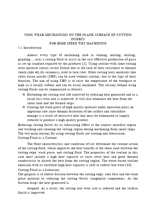
TOOL WEAR MECHANISMS ON THE FLANK SURFACE OF CUTTINGINSERTSFOR HIGH SPEED WET MACHINING5.1 IntroductionAlmost every type of machining such as turning, milling, drilling, grinding..., uses a cutting fluid to assist in the cost effective production of pa rts as set up standard required by the producer [1]. Using coolant with some cutting tools material causes severe failure due to the lack of their resistance to thermal shock (like AL2O3 ceramics), used to turn steel. Other cutting tools materials like cubic boron nitride (CBN) can be used without coolant, due to the type of their function. The aim of using CBN is to raise the temperature of the workpice to high so it locally softens and can be easily machined.The reasons behind using cutting fluids can be summarized as follows.® Extending the cutting tool life achieved by reducing heat generated and as a result less wear rate is achieved. It will also eliminate the heat from theshear zone and the formed chips.® Cooling the work piece of high quality materia l under operation plays an important role since thermal distortion of the surface and subsurfacedamage is a result of excessive heat that must be eliminated or largelyreduced to produce a high quality product.Reducing cutting forces by its lubricating e ffect at the contact interface region and washing and cleaning the cutting region during machining from small chips. The two main reasons for using cutting fluids are cooling and lubrication.Cutting Fluid as a Coolant:The fluid characteristics and condition of use determine the coolant action of the cutting fluid, which improves the heat transfer at the shear zone between the cutting edge, work piece, and cutting fluid. The properties of the coolant in this case must include a high heat capacity to carry away heat and good thermal conductivity to absorb the heat from the cutting region. The water-based coolant emulsion with its excellent high heat capacity is able to reduce tool wear [44]. Cutting Fluid as a Lubricant:The purpose is to reduce friction bet ween the cutting edge, rake face and the work piece material or reducing the cutting forces (tangential component). As the friction drops the heat generated isdropped. As a result, the cutting tool wear rate is reduced and the surface finish is improved.Cutting Fluid PropertiesFree of perceivable odorPreserve clarity throughout lifeKind and unirritated to skin and eyes.Corrosion protection to the machine parts and work piece.Cost effective in terms off tool life, safety, dilution ratio, and fluid lif e.[1]5.1.1 Cutting Fluid TypesThere are two major categories of cutting fluidsNeat Cutting OilsNeat cutting oils are poor in their coolant characteristics but have an excellent lubricity. They are applied by flooding the work area by a pump and re-circulated through a filter, tank and nozzles. This type is not diluted by water, and may contain lubricity and extreme-pressure additives to enhance their cutting performance properties. The usage of this type has been declining for their poor cooling ability, causing fire risk, proven to cause health and safety risk to the operator [1].® Water Based or Water Soluble Cutting FluidsThis group is subdivided into three categories:1.Emulsion ` mineral soluble' white-milky color as a result of emulsion of oil inwater. Contain from 40%-80% mineral oil and an emulsifying agent beside corrosion inhibitors, beside biocide to inhibit the bacteria growth.2.Micro emulsion `semi-synthetic' invented in 1980's, has less oil concentrationand/or higher emulsifier ratio 10%-40% oil. Due to the high levels ofemulsifier the oil droplet size in the fluid are smaller which make the fluid more translucent and easy to see the work piece during operation. Otherimportant benefit is in its ability to emulsify any leakage of oil from themachine parts in the cutting fluid, a corrosion inhibitors, and bacteria control.3.Mineral oil free `synthetic' is a mix of chemicals, water, bacteria control,corrosion inhibitors, and dyes. Does not contain any mineral oils, andprovides good visibility.23 to the work piece. bare in mind that the lack of mineral oil in this type of cuttingfluid needs to take more attention to machine parts lubrication since it should not leave an oily film on the machine parts, and might cause seals degradation due the lack of protection.5.1.2 Cutting Fluid SelectionMany factors influence the selection of cutting fluid; mainly work piece material, type of machining operation, machine tool parts, paints, and seals. Table 5-1 prepared at the machine tool industry res earch association [2] provides suggestions on the type of fluid to be used.5.1.3 Coolant ManagementTo achieve a high level of cutting fluids performance and costeffectiveness, a coolant recycling system should be installed in the factory. This system will reduce the amount of new purchased coolant concentrate and coolant disposable, which will reduce manufacturing cost. It either done by the company itself or be rented out, depends on the budget and management policy of the company [1].Table 5-1 Guide to the selection of cutting fluids for general workshop applications.Machining operation Workpiece materialFree machining and low - carbon Medium- Carbon steels High Carbon and alloy steels Stainlessand heattreated GrindingClear type soluble oil, semi synthetic or chemical Turning General purpose, soluble oil, semi synthetic or synthetic fluid Extreme-pressuresoluble oil,semi-synthetic orsyntheticfluid Milling General purpose, soluble oil, semi synthetic or synthetic Extreme- pressure soluble oil, semi- synthetic or synthetic Extreme-pressuresoluble oil,semi-synthetic orsyntheticfluid(neat cutting oilsmay beDrillingExtreme- pressure soluble oil, semi- synthetic or GearShapping Extreme-pressure soluble oil, Neat-cutting oils preferable HobbingExtreme-pressure soluble oil, semi-synthetic or synthetic fluid (neat cutting oils may be Neat-cutti ng oils BratchingExtreme-pressure soluble oil, semi-synthetic or synthetic fluid (neat Tapping Extreme-pressure soluble oil, semi-synthetic or Neat-cuttingpreferableNote: some entreis deliberately extend over two or more columns, indicating awide range of possible applications. Other entries are confined to aspecific class of work material.Adopt ed f rom Edw ard and Wri ght [2]5.2 Wear Mechanisms Under Wet High Speed M achiningIt is a common belief that coolant usage in metal cutting reduces cuttingtemperature and extends tools life. However, this researchshowed that this is not necessarily true to be generalized overcutting inserts materials. Similar research was ca rried out ondifferent cutting inserts materials and cutting conditionssupporting our results. Gu et al [36] have recorded adifference in tool wear mechanisms between dry and wetcutting of C5 milling inserts. Tonshoff et al [44] alsoexhibited different wear mechanisms on AL 2O 3/TiC inserts inmachining ASTM 5115, when using coolants emulsionscompared to dry cutting. In addition, Avila and Abrao [20]experienced difference in wear mechanisms activated at theflank side, when using different coolants in t estingAL 2O 3lTiC tools in machining AISI4340 steel. The wearmechanisms and the behavior of the cutting inserts studied inthis research under wet high speed-machining (WHSM)condition is not fully understood. Therefore, it was theattempt of this research to focus on the contributions incoating development and coating techniques of newlydeveloped materials in order to upgrade their performance attough machining conditions. This valuable research providesinsight into production timesavings and increase inprofitability. Cost reductions are essential in the competitiveglobal economy; thus protecting local markets and consistingin the search of new ones.5.3 Experimental Observations on Wear Mechanisms of Un-CoatedCemented Carbide Cutting Inserts in High Speed WetMachiningIn this section, the observed wear mechanisms are presented of uncoated cemented carbide tool (KC313) in machining ASTM 4140 steel under wet condition. The overall performance of cemented carbide under using emulsion coolant has been improved in terms of extending tool life and reducing machining cost. Different types of wear mechanisms were activated at flank side of cutting inserts as a result of using coolant emulsion during machining processes. This was due to the effect of coolant in reducing the average temperature of the cutting tool edge and shear zone during machining. As a result abrasive wear was reduced leading longer tool life. The materials of cutting tools behave differently to coolant because of their varied resistance to thermal shock. The following observations recorded the behavior of cemented carbide during high speed machining under wet cutting.Figure5-1 shows the flank side of cutting inserts used at a cutting speed of 180m/min. The SEM images were recorded after 7 minutes of machining. It shows micro-abrasion wear, which identified by the narrow grooves along the flank side in the direction of metal flow, supported with similar observations documented by Barnes and Pashby [41] in testing through-coolant-drilling inserts of aluminum/SiC metal matrix composite. Since the cutting edge is the weakest part of the cutting insert geometry, edge fracture started first due to the early non-smooth engagement between the tool and the work piece material. Also, this is due to stress concentrations that might lead to a cohesive failure on the transient filleted flank cutting wedge region [51, 52]. The same image of micro-adhesion wear can be seen at the side and tool indicated by the half cone27 shape on the side of cutting tool. To investigate further, a zoom in view was taken atthe flank side with a magnification of 1000 times and presented in Figure 5-2A. It shows clear micro-abrasion wear aligned in the direction of metal flow, where the cobalt binder was worn first in a hi gher wear rate than WC grains which protruded as big spherical droplets. Figure 5-2B provides a zoom-in view that was taken at another location for the same flank side. Thermal pitting revealed by black spots in different depths and micro-cracks, propagated in multi directions as a result of using coolant. Therefore, theii~ial pitting, micro-adhesion and low levels of micro-abrasion activated under wet cutting; while high levels of micro-abrasion wear is activated under dry cutting (as presented in the prev ious Chapter).Figure 5-3A was taken for a cutting insert machined at 150mlmin. It shows a typical micro-adhesion wear, where quantities of chip metal were adhered at the flank side temporarily. Kopac [53] exhibited similar finding when testing HSS-TiN drill inserts in drilling SAE1045 steel. This adhered metal would later be plucked away taking grains of WC and binder from cutting inserts material and the process continues. In order to explore other types of wear that might exist, a zoom-in view with magnification of 750 times was taken as shown in Figure5-3B. Figure 5-3B show two forms of wears; firstly, micro-thermal cracks indicated by perpendicular cracks located at the right side of the picture, and supported with similar findings of Deamley and Trent [27]. Secondly, micro-abrasion wear at the left side of the image where the WC grains are to be plucked away after the cobalt binder was severely destroyed by micro-abrasion. Cobalt binders are small grains and WC is the big size grains. The severe distort ion of the binder along with the WC grains might be due to the activation of micro-adhesion and micro-abrasionFigure 5-1 SEM image of (KC313) showing micro abrasion and micro-adhesion (wet).SEM micrographs of (KC313) at 180m/min showing micro-abrasion where cobalt binder was worn first leaving protruded WC spherical droplets (wet).(a)SEM micrographs of (KC313) at 180m/min showing thermal pitting (wet).Figure 5-2 Magnified views of (KC313) under wet cutting: (a) SEM micrographs of (KC313) at 180mlmin showing micro-abrasion where cobalt binderwas worn first leaving protruded WC spherical droplets (wet ), (b) SEMmicrographs of (KC313) at 180.m/min showing thermal pitting (wet ).SEM image showing micro-adhesion wear mechanism under 150m/min (wet).(a)SEM image showing micro-thermal cracks, and micro-abrasion.Figure 5-3 Magnified views of (KC313) at 150m/min (wet): (a) SEM image showing micro-adhesion wear mechanism under 150m/min (wet), (b) SEM image showing micro-fatigue cracks, and micro-abrasion (wet).Wear at the time of cutting conditions of speed and coolant introduction. Therefore, micro-fatigue, micro-abrasion, and micro-adhesion wear mechanisms are activated under wet condition, while high levels of micro-abrasion were observed under dry one.Next, Figure 5-4A was taken at the next lower speed (120m/min). It shows build up edge (BUE) that has sustained its existence throughout the life of the cutting tool, similar to Huang [13], Gu et al [36] and Venkatsh et al [55]. This BUE has protected the tool edge and extended its life. Under dry cutting BUE has appeared at lower speeds (90 and 60 m/min), but when introducing coolant BUE started to develop at higher speeds, This is due to the drop in shear zone temperature that affected the chip metal fl ow over the cutting tool edge, by reducing the ductility to a level higher than the one existing at dry condition cutting. As a result, chip metal starts accumulating easier at the interface between metal chip flow, cutting tool edge and crater surface to form a BUE. In addition to BUE formation, micro-abrasion wear was activated at this speed indicated by narrow grooves.To explore the possibility of other wear mechanisms a zoom-in view with a magnification of 3500 times was taken and shown in Figure 5-4B. Micro- fatigue is evident by propagated cracks in the image similar to Deamley and Trent [27] finding. Furthermore, Figure 5-4B shows indications of micro-abrasion wear, revealed by the abrasion of cobalt binder and the remains of big protruded WC grains. However, the micro-abrasion appeared at this speed of 120m/min is less severe than the same type of micro-wear observed at 150m/min speed, supported with Barnes [41] similar findings. Therefore, micro-abrasion, BUE and micro-fatigue were activated under wet condition while, adhesion, high levels micro-abrasion, and no BUE were under dry cutting.SEM i m a g e o f(KC313) showing build up e d g e under 120m/min (wet).(a)SEM i m a g e o f(KC3 13) showing micro-fatigue, and micro-abrasion (wet). Figure 5-4 SEM images of (KC313) at 120m/min (wet), (a) SEM image of (KC313). showing build up edge, (b) SEM image of(K C313) showing micro-fatigue and micro-abrasion33 Figure 5-5 is for a cutting tool machined at 90m/min, that presents a goodcapture of one stage of tool life after the BUE has been plucked away. The bottom part of the flank side shows massive metal adhesion from the work piece material. The upper part of the figure at the edge shows edge fracture. To stand over the reason of edge fracture, the zoom-in view with magnification of 2000 times is presented in Figure 5-6A. The micro-fatigue crack image can be seen as well as micro-attrition revealed by numerous holes, and supported with Lim et al [31] observations on HSS-TiN inserts. As a result of BUE fracture from the cutting tool edge, small quantities from the cutting tool material is plucked away leaving behind numerous holes. Figure 5-6B is another zoom-in view of the upper part of flank side with a magnification of 1000 times and shows micro-abrasion wear indicated by the narrow grooves. Furthermore, the exact type of micro-wear mechanism appeared at the flank side under 60 m/min. Therefore, in comparison with dry cutting at the cutting speed of 90 m/min and 60 m/min, less micro-abrasion, bigger BUE formation, and higher micro-attrition rate were activated.Figure 5-5 SEM image showing tool edge after buildup edge was plucked away.SEM image showing micro-fatigue crack, and micro-attrition.(a)SEM image showing micro-abrasion.Figure 5-6 SEM images of (KC313) at 90m/min:(a) SEM image showing micro-fatigue crack, and micro-attrition, (b) SEM image showingmicro-abrasion.5.4 Experimental Observations on Wear Mechanisms of Coated CementedCarbide with TiN-TiCN-TiN Coating in High Speed WetMachiningInvestigating the wear mechanisms of sandwich coating under wet cutting is presented in this section starting from early stages of wear. Figure 5-7 shows early tool wear starting at the cutting edge when cutting at 410m/min. Edge fracture can be seen, it has started at cutting edge due to non-smooth contact between tool, work piece, micro-abrasion and stress concentrations. To investigate further the other possible reasons behind edge fracture that leads to coating spalling, a zoom-in view with magnification of 2000 ti mes was taken and presented at Figure 5-8A. Coating fracture can be seen where fragments of TiN (upper coating) had been plucked away by metal chips. This took place as result of micro-abrasion that led to coating spalling. On the other hand, the edge is t he weakest part of the cutting insert geometry and works as a stress concentrator might lead to a cohesive failure on the transient filleted flank cutting wedge region [51, 52].Both abrasion wear and stress concentration factor leave a non-uniform edge configuration at the micro scale after machining starts. Later small metal fragments started to adhere at the developed gaps to be later plucked away by the continuous chip movement as shown in Figure 5-8A. Another view of edge fracture was taken of the same cutting tool with a magnification of 2000 times as shown in Figure 5-8B. It presents fracture and crack at the honed tool edge. A schematic figure indicated by Figure 5-9, presented the progressive coated cutting inserts failure starting at the insert edge. It was also noticed during the inserts test that failure takes place first at the inserts edge then progressed toward the flank side. Consequently, a study on optimizing the cutting edgeFigure 5-7 SEM image of (KC732) at 410m/min showing edge fractur e and micro-abrasion (wet).SEM image showing edge fracture.(a)SEM image showing fracture and crack at the honed insert edge.Figure 5-8 SEM of (KC732) at 410m/min and early wear stage (wet): (a) SEM image showing edge fracture, (b) SEM image showing fr acture and crack atthe honed insert edge.radius to improve coating adhesion, and its wear resistance, might be also a topic for future work.Figure 5-1.0A was taken after tool failure at a speed of 410m/min. It shows completely exposed substrate and severe sliding wear at the flank side. The coating exists at the crater surface and faces less wear than the flank side. Therefore it works as an upper protector for the cutting edge and most of the wear will take place at the flank side as sliding wear. Figu re 5-10B is a zoom-in view with magnification of 3500 times, and shows coating remaining at the flank side. Nonetheless, micro-abrasion and a slight tensile fracture in the direction of metalchip flow. Ezugwa et al [28] and Kato [32] have exhibited simila r finding. However, the tensile fracture in this case is less in severity than what had been observed at dry cutting. This is due to the contribution of coolant in dropping the cutting temperature, which has reduced the plastic deformation at high temperature as a result. Hence, in comparison with the dry cutting at the same speed, tensile fracture was available with less severity and micro-abrasion/sliding. However, in dry cutting high levels of micro-abrasion, high levels of tensile fracture and sliding wear occurred.Figure 5-11 was taken at early stages of wear at a speed of 360m/min. It shows sliding wear, coating spalling and a crack starting to develop between TiN and TiCN coating at honed tool edge. Figure5-12A shows nice presentation of what had been described earlier regarding the development of small fragments on the tool edge. The adhered metal fragments work along with micro-abrasion wear to cause coating spalling.SEM image showing sliding wear.(a)SEM image showing micro-abrasion and tensile fracture.Figure 5-10 SEM images of (KC732) at 410m/min after failure (wet): (a) SEM image showing sliding wear, (b) SEM image showing micro-abrasionand tensile fracture.Figure 5-11 SEM image at early stage of wear of 360m/min (wet) showing coating and spalling developing crack between TiN and TiCN layers.The size of the metal chip adhered at the edge is almost 15g. Since it is unstable it will be later plucked away taking some fragments of coatings with it and the process continues. Another zoom in view with a magnification of 5000 times for the same insert is shown in Figure 5-12B indicating a newly developed crack between the coating layers.Figure 5-13A is taken of the same insert after failure when machining at 360m/min and wet condition. Coating spalling, and sliding wear can be seen and indicated by narrow grooves. In addition, initial development of notch wear can be seen at the maximum depth of cut.Further investigation is carried out by taking a zoom in view with a magnification of 2000 times as shown in Figure 5-13B. A clear micro-abrasion wear and micro-fatigue cracks were developed as shown, which extended deeply through out the entire three coating layers deep until the substrate. Therefore, in comparison with dry cutting, micro-fatigue crack, less tensile fracture, less micro-abrasion wear were activated at wet cutting. While micro- fatigue crack, high levels of micro-abrasion, and high levels of tensile fracture are distinguish the type of wear under dry condition at the same cutting spee d.Next, Figure 5-14A is taken for cutting tools machined at 310m/min. The results are similar to the previous inserts machined at 360m/min, where adhesion of metal fragments occurred at the tool edge, sliding wear and coating spalling. In addition, the black spot appeared at the top of the figure on the crater surface is a void resulting from imperfections in the coating process. At this condition, the crater surface will be worn faster than the flank surface.SEM image showing adhered metal fragments at tool edge.(a)SEM image showing developed crack between coating layers.Figure 5-12 SEM image of (KC732) at early wear 360m/min (wet): (a) SEM image showing adhered metal fragments at tool edge, (b) SEM image showingdeveloped crack between coating layers.(a)SEM image showing coating spalling and sliding wear after tool failure(b)SEM image showing micro-abrasion, and micro-fatigue cracks developedbetween coating layersFigure 5-13 SEM image of KC732 after failure machined at 360m/min(b)(wet): (a) SEM image showing coating spalling and sliding wear after toolfailure, (b) SEM image showing micro-abrasion, and micro-fatiguecracks developed between coating layers.翻译:在高速潮湿机械加工条件下后刀面表层磨损机理5.1 介绍几乎每类型用机器制造譬如转动, 碾碎, 钻井, 研..., 使用切口流体协助零件的有效的生产当设定标准由生产商[ 1 ] 需要。
英文翻译原文:(一)BORING AND BORING MACHINESAs carried out on a lathe,boring produces circular internal profiles in hollow work-pieces or on a hole made by drilling or another process,Boring is done with cutting tools that are similar to those used in turning.Because the boring bar has to reach the full length of the bore,tool deflection and,therefore,maintainance of dimensional accuracy can be a significant problem.The boring bar must be sufficiently stiff—that is,made of a material with high elastic modulus,such as tungsten carbide–to minimize deflection and avoid vibration and chatter.Boring bars have been designed with capabilities for damping vibration.Although boring operations on relatively small work-pieces.Can be carried out on a lathe,boring mills are used for large work-pieces.These machines are either vertical or horizontal,and are capable of performing operations such as turning, facing,grooving,and chamfering.A vertical boring machine is similar to a lathe but has a vertical axis of work-piece rotation.The cutting tool(usually a single point made of M-2and M-3high-speed steel and C-7and C-8carbide)is mounted on the tool head,which is capable of vertical movement(for boring and turning)and radial movement(for facing),guided by the cross-rail.The head can be swiveled to produce conical(tapered)surfaces.In horizontal boring machine,the work-piece is mounted on a table that can move horizontally in both the axial and radial directions.The cutting tool is mounted on a spindle that rotates in the headstock,which is capable of both vertical and longitudinal movements.Drills,reamer,taps,and milling cutters can also be mounted on the machine spindle.Boring machine are available with a variety of features.Although work-piece diameters are generally1m-4m(3ft-12ft),work-piece as large as20m(60ft)can be machined in some vertical boring machines.Machine capacities range up to150kw (200hp).these machines are also available with computer numerical controls,which allow all movements to be programmed.With such controls,little operaror involvement is required and consistency and productivity are improved.Cutting speeds and feeds for boring are similar to those for turning.(For capabilities of boring operations)Jig borers are vertical boring machines with high–precision bearings.Although they are available in various sizes and used in tool rooms for making jigs and fixtures,they are now being replaced by more versatile numerical control machines.Design considerations for boring.Guidelines for efficient and economical boring operations are similar to those for turning.Additionally,the following factors should be considered:a.Whenever possible,through holes rather than blind holes should bespecified.(The term blind hole refers to a hole that does not go thoughthe thickness of the work-piece)b.The greater the length–to–bore-diameter ratio,the more difficult it is tohold dimensions because of the deflections of the boring bar due tocutting forces.c.Interrupted internal surfaces should be avoided.(2)Fundamentals of Machine Tools In many cases products form the primary forming processes must undergo further refinements in size and surface finish to meet their design specifications.To meet such precise tolerances the removal of small amounts of material is needed. Usually machine tools are used for such operation.In the United States material removal is a big business-in excess of$per year, including material,labor,overhead,and machine-tool shipments,is spent.Since60 percent of the mechanical and industrial engineering and technology graduates have something connection with the machining industry either through sale,design,or operation of machine shops,or working in related industry,it is wise for an engineering student to devote some time in his curriculum to studying material removal and machine tools.A machine tool provides the means for cutting tools to shape a workpiece to required dimensions;the machine supports the tool and the workpiece in a controlled relationship through the functioning of its basic members,which are as follow:(a)Bed,Structure or Frame.This is the main member which provides a basis for, and a connection between,the spindles and slides;the distortion and vibration under load must be kept to a minimum.(b)Slides and Sideways.The translation of a machine element(e.g.the slide)is normally achieved by straight-line motion under the constraint of accurate guiding surfaces(the slideway).(c)Spindles and Bearings.Angular displacements take place about an axis of rotation;the position of this axis must be constant within extremely fine limits in machine tools,and is ensured by the provision of precision spindles and bearings.(d)Power Unit.The electric motor is the universally adopted power unit for machine tools.By suitably positioning individual motors,belt and gear transmissions are reduced to a minimum.(e)Transmission Linkage.Linkage is the general term used to denote the mechanical,hydraulic,pneumatic or electric mechanisms which connect angular andlinear displacements in defined relationship.There are two broad divisions of machining operations:(a)Roughing,for which the metal removal rate,and consequently the cutting force,is high,but the required dimensional accuracy relatively low.(b)Finishing,for which the metal removal rate,and consequently the cutting force,is low,but the required dimensional accuracy and surface finish relatively high. It follows that static loads and dynamic loads,such as result form an unbalanced grindingwheel,are more significant in finishing operations than in roughing operations,The degree of precision achieved in any machining process will usually be influenced by the magnitude of the deflections,which occur as a result of the force acting.Machine tool frames are generally made in cast iron,although some may be steel casting or mild-steel fabrications.Cast iron is chosen because of its cheapness,rigidity, compressive strength and capacity for damping the vibrations set-up in machine operations,To avoid massive sections in castings,carefully designed systems of ribbing are used to offer the maximum resistance to bending and torsional stresses. Two basic types of ribbing are box and diagonal.The box formation is convenient to produce,apertures in walls permitting the positioning and extraction of cores. Diagonal ribbing provides greater torsional stiffness and yet permits swarf to fall between the sections;it is frequently used for lathe beds.The slides and slideways of a machine tool locate and guide members which move relative to each other,usually changing the position of the tool relative to workpiece.The movement generally takes the form of translation in a straight line, but is sometimes angular rotation, e.g.tilting the wheel-head of a universal thread-grinding machine to an angle corresponding which the helix angle of the workpiece thread.The basic geometric elements of slides are flat,vee,dovetail and cylinder.These elements may be used separately or combined in various ways according to the applications.Features of slideways are as follows:(a)Accuracy of Movement.Where a slide is to be displaced in a straight line, this line must lie in two mutually perpendicular planes and there must be no slide rotation.The general tolerance for straightness of machine tool slideways is 0~0.02mm per1000mm;on horizontal surfaces this tolerance may be disposed so thata convex surface results,thus countering the effect of"sag"of the slideway.(b)Means of Adjustment.To facilitate assembly,maintain accuracy and eliminate"play"between sliding members after wear has taken place,a strip is sometimes inserted in slides.This is called a ually,the gib is retained by socket-head screws passing through elongated slots;and is adjusted by grub-screws secured by lock nuts.(c)Lubrication.Slideways may be lubricated by either of the following systems:1)Intermittently through grease or oil nipples,a method suitable wheremovements are infrequent and speed low.2)Continuously e.g.by pumping through a metering valve and pipe-work to the point of application;the film of oil introduced between surfaces by these means must be extremely thin to avoid the slide“floating”.If sliding surfaces were optically flatoil would be squeezed out,resulting in the surfaces sticking.Hence in practice slide Sill"faces are either grourld using the edge of a cup wheel,or scraped.Both processes produee minulte surface depressions,which retain‘‘pocket”of oil,and complete separation of the parts may not occur at all points.(d)Protection.To maintain slideways in good order,the following conditions must be met:1)Ingress of foreign matter,e.g.swarf,must be prevented.Where this is no possible,it is desirable to have a form of slideway,which does not retain swarf,e.g. the inverted vee.2)Lubricating oil must be retained.The adhesive property of oil for use on vertical or inclined slide surface is important;oils are available which have been specially developed for this purpose.The adhesiveness of oil also preverts it being washed away by cutting fluids.3)Accidental damage must be prevented by protective guards.译文:(一)镗削加工和镗床像车床加工零件一样,镗床能在中空的工件或由钻削加工或其它工艺所加工的孔上进行内轮廓圆的加工。
机械类英文文献+翻译20.9 MACHINABILITYThe machinability of a material usually defined in terms of four factors:1、Surface finish and integrity of the machined part;2、Tool life obtained;3、Force and power requirements;4、Chip control.Thus, good machinability good surface finish and integrity, long tool life, and low force And power requirements. As for chip control, long and thin (stringy) cured chips, if not broken up, can severely interfere with the cutting operation by becoming entangled in the cutting zone.Because of the complex nature of cutting operations, it is difficult to establish relationships that quantitatively define the machinability of a material. In manufacturing plants, tool life and surface roughness are generally considered to be the most important factors in machinability. Although not used much any more, approximate machinability ratings are available in the example below.20.9.1 Machinability Of SteelsBecause steels are among the most important engineering materials (as noted in Chapter 5), their machinability has been studied extensively. The machinability of steels has been mainly improved by adding lead and sulfur to obtain so-called free-machining steels.Resulfurized and Rephosphorized steels. Sulfur in steels forms manganese sulfide inclusions (second-phase particles), which act as stress raisers in the primary shear zone. As a result, the chips produced break up easily and are small; this improves machinability. The size, shape, distribution, and concentration of these inclusions significantly influence machinability. Elements such as tellurium and selenium, which are both chemically similar to sulfur, act as inclusion modifiers in resulfurized steels.Phosphorus in steels has two major effects. It strengthens the ferrite, causingincreased hardness. Harder steels result in better chip formation and surface finish. Note that soft steels can be difficult to machine, with built-up edge formation and poor surface finish. The second effect is that increased hardness causes the formation of short chips instead of continuous stringy ones, thereby improving machinability.Leaded Steels. A high percentage of lead in steels solidifies at the tip of manganese sulfide inclusions. In non-resulfurized grades of steel, lead takes the form of dispersed fine particles. Lead is insoluble in iron, copper, and alumin um and their alloys. Because of its low shear strength, therefore, lead acts as a solid lubricant (Section 32.11) and is smeared over the tool-chip interface du ring cutting. This behavior has been verified by the presence of high concentra tions of lead on the tool-side face of chips when machining leaded steels.When the temperature is sufficiently high-for instance, at high cutting spee ds and feeds (Section 20.6)—the lead melts directly in front of the tool, acting as a liquid lubricant. In addition to this effect, lead lowers the shear stress in the primary shear zone, reducing cutting forces and power consumption. Lead can be used in every grade of steel, such as 10xx, 11xx, 12xx, 41xx, etc. Le aded steels are identified by the letter L between the second and third numeral s (for example, 10L45). (Note that in stainless steels, similar use of the letter L means “low carbon,”a condition that improves their corrosion resistance.)However, because lead is a well-known toxin and a pollutant, there are se rious environmental concerns about its use in steels (estimated at 4500 tons of lead consumption every year in the production of steels). Consequently, there is a continuing trend toward eliminating the use of lead in steels (lead-free ste els). Bismuth and tin are now being investigated as possible substitutes for lea d in steels.Calcium-Deoxidized Steels. An important development is calcium-deoxidize d steels, in which oxide flakes of calcium silicates (CaSo) are formed. These f lakes, in turn, reduce the strength of the secondary shear zone, decreasing tool-chip interface and wear. Temperature is correspondingly reduced. Consequently, these steels produce less crater wear, especially at high cutting speeds.Stainless Steels. Austenitic (300 series) steels are generally difficult to mac hine. Chatter can be s problem, necessitating machine tools with high stiffness. However, ferritic stainless steels (also 300 series) have good machinability. Martensitic (400 series) steels are abrasive, tend to form a built-up edge, and req uire tool materials with high hot hardness and crater-wear resistance. Precipitati on-hardening stainless steels are strong and abrasive, requiring hard and abrasio n-resistant tool materials.The Effects of Other Elements in Steels on Machinability. The presence of aluminum and silicon in steels is always harmful because these elements com bine with oxygen to form aluminum oxide and silicates, which are hard and a brasive. These compounds increase tool wear and reduce machinability. It is es sential to produce and use clean steels.Carbon and manganese have various effects on the machinability of steels, depending on their composition. Plain low-carbon steels (less than 0.15% C) c an produce poor surface finish by forming a built-up edge. Cast steels are mor e abrasive, although their machinability is similar to that of wrought steels. To ol and die steels are very difficult to machine and usually require annealing pr ior to machining. Machinability of most steels is improved by cold working, w hich hardens the material and reduces the tendency for built-up edge formation.Other alloying elements, such as nickel, chromium, molybdenum, and vana dium, which improve the properties of steels, generally reduce machinability. T he effect of boron is negligible. Gaseous elements such as hydrogen and nitrog en can have particularly detrimental effects on the properties of steel. Oxygen has been shown to have a strong effect on the aspect ratio of the manganese sulfide inclusions; the higher the oxygen content, the lower the aspect ratio an d the higher the machinability.In selecting various elements to improve machinability, we should consider the possible detrimental effects of these elements on the properties and strengt h of the machined part in service. At elevated temperatures, for example, lead causes embrittlement of steels (liquid-metal embrittlement, hot shortness; see Se ction 1.4.3), although at room temperature it has no effect on mechanical prop erties.Sulfur can severely reduce the hot workability of steels, because of the fo rmation of iron sulfide, unless sufficient manganese is present to prevent such formation. At room temperature, the mechanical properties of resulfurized steelsdepend on the orientation of the deformed manganese sulfide inclusions (aniso tropy). Rephosphorized steels are significantly less ductile, and are produced so lely to improve machinability.20.9.2 Machinability of Various Other MetalsAluminum is generally very easy to machine, although the softer grades te nd to form a built-up edge, resulting in poor surface finish. High cutting speed s, high rake angles, and high relief angles are recommended. Wrought aluminu m alloys with high silicon content and cast aluminum alloys may be abrasive; they require harder tool materials. Dimensional tolerance control may be a pro blem in machining aluminum, since it has a high thermal coefficient of expans ion and a relatively low elastic modulus.Beryllium is similar to cast irons. Because it is more abrasive and toxic, t hough, it requires machining in a controlled environment.Cast gray irons are generally machinable but are. Free carbides in castings reduce their machinability and cause tool chipping or fracture, necessitating to ols with high toughness. Nodular and malleable irons are machinable with hard tool materials.Cobalt-based alloys are abrasive and highly work-hardening. They require sharp, abrasion-resistant tool materials and low feeds and speeds.Wrought copper can be difficult to machine because of built-up edge form ation, although cast copper alloys are easy to machine. Brasses are easy to ma chine, especially with the addition pf lead (leaded free-machining brass). Bronz es are more difficult to machine than brass.Magnesium is very easy to machine, with good surface finish and prolong ed tool life. However care should be exercised because of its high rate of oxi dation and the danger of fire (the element is pyrophoric).Molybdenum is ductile and work-hardening, so it can produce poor surfac e finish. Sharp tools are necessary.Nickel-based alloys are work-hardening, abrasive, and strong at high tempe ratures. Their machinability is similar to that of stainless steels.Tantalum is very work-hardening, ductile, and soft. It produces a poor surf ace finish; tool wear is high.Titanium and its alloys have poor thermal conductivity (indeed, the lowest of all metals), causing significant temperature rise and built-up edge; they can be difficult to machine.Tungsten is brittle, strong, and very abrasive, so its machinability is low, although it greatly improves at elevated temperatures.Zirconium has good machinability. It requires a coolant-type cutting fluid, however, because of the explosion and fire.20.9.3 Machinability of Various MaterialsGraphite is abrasive; it requires hard, abrasion-resistant, sharp tools.Thermoplastics generally have low thermal conductivity, low elastic modul us, and low softening temperature. Consequently, machining them requires tools with positive rake angles (to reduce cutting forces), large relief angles, small depths of cut and feed, relatively high speeds, and proper support of the work piece. Tools should be sharp.External cooling of the cutting zone may be necessary to keep the chips f rom becoming “gummy”and sticking to the tools. Cooling can usually be achi eved with a jet of air, vapor mist, or water-soluble oils. Residual stresses may develop during machining. To relieve these stresses, machined parts can be an nealed for a period of time at temperatures ranging from to ( to ), and then cooled slowly and uniformly to room temperature.Thermosetting plastics are brittle and sensitive to thermal gradients during cutting. Their machinability is generally similar to that of thermoplastics.Because of the fibers present, reinforced plastics are very abrasive and are difficult to machine. Fiber tearing, pulling, and edge delamination are significa nt problems; they can lead to severe reduction in the load-carrying capacity of the component. Furthermore, machining of these materials requires careful rem oval of machining debris to avoid contact with and inhaling of the fibers.The machinability of ceramics has improved steadily with the development of nanoceramics (Section 8.2.5) and with the selection of appropriate processi ng parameters, such as ductile-regime cutting (Section 22.4.2).Metal-matrix and ceramic-matrix composites can be difficult to machine, d epending on the properties of the individual components, i.e., reinforcing or wh iskers, as well as the matrix material.20.9.4 Thermally Assisted MachiningMetals and alloys that are difficult to machine at room temperature can be machined more easily at elevated temperatures. In thermally assisted machinin g (hot machining), the source of heat—a torch, induction coil, high-energy bea m (such as laser or electron beam), or plasma arc—is forces, (b) increased too l life, (c) use of inexpensive cutting-tool materials, (d) higher material-removal rates, and (e) reduced tendency for vibration and chatter.It may be difficult to heat and maintain a uniform temperature distribution within the workpiece. Also, the original microstructure of the workpiece may be adversely affected by elevated temperatures. Most applications of hot machi ning are in the turning of high-strength metals and alloys, although experiment s are in progress to machine ceramics such as silicon nitride.SUMMARYMachinability is usually defined in terms of surface finish, tool life, force and power requirements, and chip control. Machinability of materials depends n ot only on their intrinsic properties and microstructure, but also on proper sele ction and control of process variables.20.9 可机加工性一种材料的可机加工性通常以四种因素的方式定义:1、分的表面光洁性与表面完整性。
毕业设计(论文)外文资料翻译系部:专业:姓名:学号:外文出处:English For Electromechanical(用外文写)Engineering附件:1.外文资料翻译译文;2.外文原文。
附件1:外文资料翻译译文机床机床是用于切削金属的机器。
工业上使用的机床要数车床、钻床和铣床最为重要。
其它类型的金属切削机床在金属切削加工方面不及这三种机床应用广泛。
车床通常被称为所有类型机床的始祖。
为了进行车削,当工件旋转经过刀具时,车床用一把单刃刀具切除金属。
用车削可以加工各种圆柱型的工件,如:轴、齿轮坯、皮带轮和丝杠轴。
镗削加工可以用来扩大和精加工定位精度很高的孔。
钻削是由旋转的钻头完成的。
大多数金属的钻削由麻花钻来完成。
用来进行钻削加工的机床称为钻床。
铰孔和攻螺纹也归类为钻削过程。
铰孔是从已经钻好的孔上再切除少量的金属。
攻螺纹是在内孔上加工出螺纹,以使螺钉或螺栓旋进孔内。
铣削由旋转的、多切削刃的铣刀来完成。
铣刀有多种类型和尺寸。
有些铣刀只有两个切削刃,而有些则有多达三十或更多的切削刃。
铣刀根据使用的刀具不同能加工平面、斜面、沟槽、齿轮轮齿和其它外形轮廓。
牛头刨床和龙门刨床用单刃刀具来加工平面。
用牛头刨床进行加工时,刀具在机床上往复运动,而工件朝向刀具自动进给。
在用龙门刨床进行加工时,工件安装在工作台上,工作台往复经过刀具而切除金属。
工作台每完成一个行程刀具自动向工件进给一个小的进给量。
磨削利用磨粒来完成切削工作。
根据加工要求,磨削可分为精密磨削和非精密磨削。
精密磨削用于公差小和非常光洁的表面,非精密磨削用于在精度要求不高的地方切除多余的金属。
车床车床是用来从圆形工件表面切除金属的机床,工件安装在车床的两个顶尖之间,并绕顶尖轴线旋转。
车削工件时,车刀沿着工件的旋转轴线平行移动或与工件的旋转轴线成一斜角移动,将工件表面的金属切除。
车刀的这种位移称为进给。
车刀装夹在刀架上,刀架则固定在溜板上。
溜板是使刀具沿所需方向进行进给的机构。
中英文翻译原文:Comment on medicines and chemical reagents package machineryconceptual designIn recent years, Carry out GMP (medicines and chemical reagents produces specifications of quality) attestation system because of sustained our country economic situation rise and country to pharmacy industry mandatory. Medicines and chemical reagents package machinery has got quite great progress. The new product increases by gradually. Engineering level has had very big improvement. But be returning very big gaps back to existence compared with international standards. Level being close to 60%'s product cannot to reach upper developed country century eighties. Large-scale advanced equipment is dependent on entrance mainly. Low our country medicines and chemical reagents package machinery engineering level is that the design designing personnel low level from our country enterprise arouses to a great extent.One, our country medicines and chemical reagents package machinery current situation analysesOur country medicines and chemical reagents package machinery still has bigger gap compared with advanced international level. What time is insufficient on domestic medicines and chemical reagents package machinery design under main existence1) Backward domestic mechanical performance medicines and chemical reagents package machinery mostly, accuracy low velocity, is slow, stationarity dispatches package machinery travel process to contain large amount of dyadic complicated intermittence motion. Come to come true mainly from the cam, the connecting rod. But, many design that the personnel is unable to require that the independence designs the parameter calculating cam bar linkage kinematics and dynamics according to job cycle picture and accuracy. Be only the surveying and mapping carrying out a piecemeal that the abroad model machine cam connecting rod part is dismantled down simplely. Bring about actuating mechanism error is very big. That domestic medicines and chemical reagents package machinery runs speed mostly is more general than hanging down according to cutting frequency if the aluminium moulds bubble coverpacker's for 100 one 300 mins, full-automatic medicine box packer dress box speed 50- 200 boxes/ ms in. But, on the international, the advanced aluminium moulds rushing steeping cover packer cutting frequency be able to reach 600 mins. Full-automatic medicine box packer dress box speed is able to reach 600 ~ 800 box/ mins. Not only working speed of domestic medicines and chemical reagents package machinery is slow. And, the partner has bigger noise.2) Is under the control of horizontal backward. Domestic medicines and chemical reagents package machinery controls low, automation of level difference mostly , the malfunction leads height. (Main package machinery finger box dress controls domestic medicines and chemical reagents with drinking wine holding machinery with) adopt PLC to do a scene mostly. But, advanced medicines and chemical reagents package machinery realizes supervisory control abroad mostly from computer system. Under the control of horizontal relatively backward. Great majority domestic medicines and chemical reagents package machinery automation sex is relatively poor. Adopt a single to produce a pattern first commonly. The full-automatic production line is few. Two is that full-automation works cannot to achieve. Require that the manpower feeds in raw material. Hand movement enchases. If in a little paper box packer, Page, paper box all needs medicine board , specifications paper to move charging personally. And require specially-assigned person to pay attention to if specifications, medicine board, paper box already finish using at any time. Happen to avoid bringing about machine racing or bringing about incomplete specifications, medicine board, and medicine box phenomenon. Other, domestic medicines and chemical reagents package mechanic failure rates are higher. Control a component (if the relay, electromagnetic valve, contactor, breaker etc.) etc. are often easy to damage. Halt also to frequently occur the malfunction.3) Functions are unitary, expansion sex is bad. Medicines and chemical reagents package machinery is that the form designs that specifically for specially appointed package. The general specification range inner in regulation is adjustable. But, a lot of our country medicines and chemical reagents package machinery considers insufficiency when designing that. Be not that reforming going a step further sets apart sufficient space. Cause the machinery designing that to be able to only adapt to the form board in several kinds simplicities. Change not adapting to wrapping material or the form board dimension. Fit in with even. The package finished product mass giving birth to a child is neither nice.4) Considers deficiency synthetically. Resource does not fully utilize. Our country medicines and chemical reagents there exists the chaos phenomenon in package machinery design. A lot of machinery designs that the personnel drags to the electric motor moving the synchrony technology, the servo drive technology do not knows. The problem simple electrical equipment available is resolved uses complicated mechanism to come to come true but. Some though the control organ works to come having adopt the synchrony electric motor to wait for a device. But choose block of wood ding-dang. The maximum having brought about resource not only wastes this condition. And make machinery function designing that low.5) Model is inflexible. Model seldom considering machinery time medicines and chemical reagents of our country package machinery design. Many machine molding that the manufacturer produces is not beautiful do not have model even. Give person feeling to rigid, to inflexible, not to have vigor. A few medicine box packers are middle. The nut all assembles screw on the machine outside board. But, the oil cup and flow nipple that a little lubrication uses also can be seen everywhere. Be stained fully with a greasy dirt easy to use machine everywhere time oiling. Impression is rough to person. No beautiful.Two, medicines and chemical reagents package machinery conceptual design contentPeople long-term study passes. Define conceptual design being: "Have been ascertaining the mission queen. Pass abstract-relation. Design the function structure. Explore appropriate effect principle and their combination waiting. Ascertain out basic finding the solution approach. Reach find the solution scheme. This part of the conceptual design designing that the job is called conceptual design is referred to make the queen who designs purpose and now has condition clear. The designer searches for many-sided knowledge. Analysis abstracts the solution on generating dyadic broad frame significance the day after tomorrow. Medicines and chemical reagents package machinery conceptual design demands according to each product life cycle stages. Carrying out the product function creates , the function breaks up as well as the function and son are functional physical design: That conception and systematization carrying out the scheme satisfying the operating principle that the function and structure demand finding the solution and carrying out the operating principle carrier realizing the function structure's design the conceptual design process is that one finds the solution realizing a function's , satisfies the various technologyand various there existing in economic target's , possibility scheme well ultimate for sure synthetically optimum scheme process. The conceptual design effect embodies in the product design early phase stage mainly. Chief architect is based on functional need of product but primitive conception and impulsion sprouting out form the product main body frame. And, it responds to every main module and module including. In order to accomplishing overall layout and the exterior, the first step designs that. And then carry out the optimization appraising a sum. Ascertain the overall design plan. Design that the personnel carries out the chief architect design thought going to designing middle concretely again from every part. Detail designs realization. The conceptual design putting medicines and chemical reagents package machinery into practice demands to design that the personnel reinforces the cognition to medicines and chemical reagents package first. Deepen the connotation understanding medicines and chemical reagents packages. Introduce modern package idea. Be in line with the international conventions actively. Modern package is to ensure the product safety not only. Make product transportation convenient. And be getting up propagate, environmental protection, defends against false. Attractive looks waits for the many-sided effect. Wrap up contents additional information. The medicines and chemical reagents package machinery design personnel should show solicitude for development of package system closely. Go deep into the handicraft studying package. Know demand of development of wrapping material and the person to machinery product very well. Only when such ability designs that out satisfy the high tone machinery product that the consumer demands. Medicines and chemical reagents package machinery conceptual design content has mainly:1) Makes the design mission clear. Be ready for feasibility analysis. The designer designs initial stage working in being in progress. Respond to the feasibility considering a product sufficiently. One aspect is the marketplace thinking. Include the production marketing, product raw material, the fabricating cost thinking: Another aspect is thinking that the product processes. Include thinking now having a working ability, processing handicraft, processing the function and periphery supporting industry. Periphery supporting environment thinking points to the local enterprise working ability mainly processes level, heat treatment handicraft and the infrastructural facilities construction etc.2) Function design. Great majority our country medicines and chemical reagents package machinery is the same kind model copying to abroad. But peculiar nationalconditions because of our country existence. Must carry out appropriate reforming on the product. To satisfy request of our country. But fault blindly copy blindly. The machinery designing that is packed in, irrigates the dress function outside except needing to satisfy a box. We must consider the additional function packing machinery. If in package box should add a counting cup. The medicine spoon waits an utensil down. Be put into use with convenience of customers. In machine, kind of aspect developing can design comparatively advanced machinery. If sterile pack machinery, the package machinery retaining freshness etc.Can develop the corollary equipment selling complete sets of equipment and the post-processing at reduced prices in the medicines and chemical reagents package front.3) Functions decomposition. Medicines and chemical reagents package machinery belongs to the integration of machinery with electronics product. Should consider every function all round time design. Sort Er Yan. The medicines and chemical reagents package machinery function may divide 3 major parts being that organization moves, monitors biography feel, the information processing and controlling a function basically. The function subdivides organization motion according to may not kind with machine , packer may be molding , heat-seal , pressure trace mark, according to cutting 4 big functions if the aluminum moulds bubble cover. But, paper box package machinery may be that the box opens, paper box transfers, breaks tongue , functions such as inserting tongue , flattening and putting a batch number up mark poison board under paper folding, deducing paper feed. Want to consider machinery lubrication, safe functions such as running, packing hygiene of machinery too in the process of design. This demands the technology designing that the personnel considers detecting sufficiently. Brightness, machine, electricity integration technology, computer art. Intersection between the pneumatic technology, the logistics technology connection.4) Organization is designed. Be to realize the predetermined function. We need to use different organization. This needs the part synthesizing each considering a complete machine among one process. Use the product designing that while satisfying the usage request. Structure is simple, pragmatic. Medicines and chemical reagents package machinery organization designs time. Respond to the principle choosing appropriate organization motion and constituting. Think sufficiently to realize what specially appointed motion needs organization. If cam organization. Bar linkage. Cam bar linkage. Respond to the technology wielding separation drive at the same time.Think that the transmission shaft designs a problem (if castellated shaft and ladder axis etc.) and drive are systematic synthetically. Design that process middle should cut down the effect that the uncertainty factor brings about to the full. Messenger organization operation is stable. Design that machinery carries out kinetic methods of analysis answering now and then. With lifting, machinery runs speed and stationarity. Should think that various packing machinery, adjustable, holds the mistake, but expansion, stationarity as well as beautiful-rization besides. Run after machinery is deft but stable. Design process but consult package machinery design of all kinds strong point. Draw other machinery (if plastic machinery, prints machinery) merit at the same time. Design the outside except carrying out organization. Return approach back to the realization should think that every function is other. If vacuum, electrical equipment waits under the control of. To expect that optimum combination is a product's turn.5) System under the control of schemes design. In medicines and chemical reagents package machinery, a very important part is that real time detecting is back-off to every organization. To ensure that equipment operation is smooth. Now many machinery products has selected and used large amount of photo electricity switch being the detecting component. Equipment has such as PC detecting bubble cover system on some machinery and the like system. This need all designs that meticulously. And, the general naval company is an integral whole.Three, concluding remarksThe thought a concept is designed melts to enter medicines and chemical reagents package machinery design being able to fall off designing a fault. Shorten a design cycle. Accelerate the product exploitation. Make the product designing that more rational, have affinity, more suitable man-machine project more. It is also that the main means costing down and improving enterprise competition is short of passive competition aspect backward for improving medicines and chemical reagents package machinery design at the same time. To adapt to the challenge that "queen GMP times" brings about. Design that the personnel must take product conceptual design seriously. Deepen the significance understanding conceptual design's.译文论药品包装机械的概念设计近年来,由于我国经济形势的持续高涨和国家对制药行业强制性推行GMP(药品生产质量规范)认证制度,药品包装机械取得了长足的进步。
机械类外文文献及翻译(文档含中英文对照即英文原文和中文翻译)原文:GEAR AND SHAFT INTRODUCTIONAbstract:The important position of the wheel gear and shaft can't falter in traditional machine and modern machines.The wheel gear and shafts mainly install the direction that delivers the dint at the principal axis box. The passing to process to make them can is divided into many model numbers, using for many situations respectively. So we must be the multilayers to the understanding of the wheel gear and shaft in many ways .Key words: Wheel gear; ShaftIn the force analysis of spur gears, the forces are assumed to act in a single plane. We shall study gears in which the forces have three dimensions. The reason for this, in the case of helical gears, is that the teeth are not parallel to the axis of rotation. And in the case ofbevel gears, the rotational axes are not parallel to each other. There are also other reasons, as we shall learn.Helical gears are used to transmit motion between parallel shafts. The helix angle is the same on each gear, but one gear must have a right-hand helix and the other a left-hand helix. The shape of the tooth is an involute helicoid. If a piece of paper cut in the shape of a parallelogram is wrapped around a cylinder, the angular edge of the paper becomes a helix. If we unwind this paper, each point on the angular edge generates an involute curve. The surface obtained when every point on the edge generates an involute is called an involute helicoid.The initial contact of spur-gear teeth is a line extending all the way across the face of the tooth. The initial contact of helical gear teeth is a point, which changes into a line as the teeth come into more engagement. In spur gears the line of contact is parallel to the axis of the rotation; in helical gears, the line is diagonal across the face of the tooth. It is this gradual of the teeth and the smooth transfer of load from one tooth to another, which give helical gears the ability to transmit heavy loads at high speeds. Helical gears subject the shaft bearings to both radial and thrust loads. When the thrust loads become high or are objectionable for other reasons, it may be desirable to use double helical gears. A double helical gear (herringbone) is equivalent to two helical gears of opposite hand, mounted side by side on the same shaft. They develop opposite thrust reactions and thus cancel out the thrust load. When two or more single helical gears are mounted on the same shaft, the hand of the gears should be selected so as to produce the minimum thrust load.Crossed-helical, or spiral, gears are those in which the shaft centerlines are neither parallel nor intersecting. The teeth of crossed-helical fears have point contact with each other, which changes to line contact as the gears wear in. For this reason they will carry out very small loads and are mainly for instrumental applications, and are definitely not recommended for use in the transmission of power. There is on difference between a crossed heli : cal gear and a helical gear until they are mounted in mesh with each other. They are manufactured in the same way. A pair of meshed crossed helical gears usually have the same hand; that is ,a right-hand driver goes with a right-hand driven. In the design of crossed-helical gears, the minimum sliding velocity is obtained when the helix angle areequal. However, when the helix angle are not equal, the gear with the larger helix angle should be used as the driver if both gears have the same hand.Worm gears are similar to crossed helical gears. The pinion or worm has a small number of teeth, usually one to four, and since they completely wrap around the pitch cylinder they are called threads. Its mating gear is called a worm gear, which is not a true helical gear. A worm and worm gear are used to provide a high angular-velocity reduction between nonintersecting shafts which are usually at right angle. The worm gear is not a helical gear because its face is made concave to fit the curvature of the worm in order to provide line contact instead of point contact. However, a disadvantage of worm gearing is the high sliding velocities across the teeth, the same as with crossed helical gears.Worm gearing are either single or double enveloping. A single-enveloping gearing is onein which the gear wraps around or partially encloses the worm.. A gearing in which each element partially encloses the other is, of course, a double-enveloping worm gearing. The important difference between the two is that area contact exists between the teeth of double-enveloping gears while only line contact between those of single-enveloping gears. The worm and worm gear of a set have the same hand of helix as for crossed helical gears, but the helix angles are usually quite different. The helix angle on the worm is generally quite large, and that on the gear very small. Because of this, it is usual to specify the lead angle on the worm, which is the complement of the worm helix angle, and the helix angle on the gear; the two angles are equal for a 0-deg. Shaft angle.When gears are to be used to transmit motion between intersecting shaft, some of bevel gear is required. Although bevel gear are usually made for a shaft angle of 0 deg. They may be produced for almost any shaft angle. The teeth may be cast, milled, or generated. Only the generated teeth may be classed as accurate. In a typical bevel gear mounting, one of the gear is often mounted outboard of the bearing. This means that shaft deflection can be more pronounced and have a greater effect on the contact of teeth. Another difficulty, which occurs in predicting the stress in bevel-gear teeth, is the fact the teeth are tapered.Straight bevel gears are easy to design and simple to manufacture and give very good results in service if they are mounted accurately and positively. As in the case of squr gears, however, they become noisy at higher values of the pitch-line velocity. In these cases it is often go : od design practice to go to the spiral bevel gear, which is the bevel counterpart of thehelical gear. As in the case of helical gears, spiral bevel gears give a much smoother tooth action than straight bevel gears, and hence are useful where high speed are encountered.It is frequently desirable, as in the case of automotive differential applications, to have gearing similar to bevel gears but with the shaft offset. Such gears are called hypoid gears because their pitch surfaces are hyperboloids of revolution. The tooth action between such gears is a combination of rolling and sliding along a straight line and has much in common with that of worm gears.A shaft is a rotating or stationary member, usually of circular cross section, having mounted upon it such elementsas gears, pulleys, flywheels, cranks, sprockets, and other power-transmission elements. Shaft may be subjected to bending, tension, compression, or torsional loads, acting singly or in combination with one another. When they are combined, one may expect to find both static and fatigue strength to be important design considerations, since a single shaft may be subjected to static stresses, completely reversed, and repeated stresses, all acting at the same time.The word “shaft” covers numerous v ariations, such as axles and spindles. Anaxle is a shaft, wither stationary or rotating, nor subjected to torsion load. A shirt rotating shaft is often called a spindle.When either the lateral or the torsional deflection of a shaft must be held to close limits, the shaft must be sized on the basis of deflection before analyzing the stresses. The reason for this is that, if the shaft is made stiff enough so that the deflection is not too large, it is probable that the resulting stresses will be safe. But by no means should the designer assume that they are safe; it is almost always necessary to calculate them so that he knows they are within acceptable limits. Whenever possible, the power-transmission elements, such as gears or pullets, should be located close to the supporting bearings, This reduces the bending moment, and hence the deflection and bending stress.Although the von Mises-Hencky-Goodman method is difficult to use in design of shaft, it probably comes closest to predicting actual failure. Thus it is a good way of checking a shaft that has already been designed or of discovering why a particular shaft has failed in service. Furthermore, there are a considerable number of shaft-design problems in which the dimension are pretty well limited by other considerations, such as rigidity, and it is only necessary for the designer to discover something about the fillet sizes, heat-treatment,and surface finish and whether or not shot peening is necessary in order to achieve the required life and reliability.Because of the similarity of their functions, clutches and brakes are treated together. In a simplified dynamic representation of a friction clutch, or brake, two in : ertias I and I traveling at the respective angular velocities W and W, one of which may be zero in the case of brake, are to be brought to the same speed by engaging the clutch or brake. Slippage occurs because the two elements are running at different speeds and energy is dissipated during actuation, resulting in a temperature rise. In analyzing the performance of these devices we shall be interested in the actuating force, the torque transmitted, the energy loss and the temperature rise. The torque transmitted is related to the actuating force, the coefficient of friction, and the geometry of the clutch or brake. This is problem in static, which will have to be studied separately for eath geometric configuration. However, temperature rise is related to energy loss and can be studied without regard to the type of brake or clutch because the geometry of interest is the heat-dissipating surfaces. The various types of clutches and brakes may be classified as fllows:. Rim type with internally expanding shoes. Rim type with externally contracting shoes. Band type. Disk or axial type. Cone type. Miscellaneous typeThe analysis of all type of friction clutches and brakes use the same general procedure. The following step are necessary:. Assume or determine the distribution of pressure on the frictional surfaces.. Find a relation between the maximum pressure and the pressure at any point. Apply the condition of statical equilibrium to find (a) the actuating force, (b) the torque, and (c) the support reactions.Miscellaneous clutches include several types, such as the positive-contact clutches, overload-release clutches, overrunning clutches, magnetic fluid clutches, and others.A positive-contact clutch consists of a shift lever and two jaws. The greatest differences between the various types of positive clutches are concerned with the design of the jaws. To provide a longer period of time for shift action during engagement, the jaws may be ratchet-shaped, or gear-tooth-shaped. Sometimes a great many teeth or jaws are used, and they may be cut either circumferentially, so that they engage by cylindrical mating, or on the faces of the mating elements.Although positive clutches are not used to the extent of the frictional-contact type, they do have important applications where synchronous operation is required.Devices such as linear drives or motor-operated screw drivers must run to definite limit and then come to a stop. An overload-release type of clutch is required for these applications. These clutches are usually spring-loaded so as to release at a predetermined toque. The clicking sound which is heard when the overload point is reached is considered to be a desirable signal.An overrunning clutch or coupling permits the driven member of a machine to “freewheel” or “overrun” bec ause the driver is stopped or because another source of power increase the speed of the driven. This : type of clutch usually uses rollers or balls mounted between an outer sleeve and an inner member having flats machined around the periphery. Driving action is obtained by wedging the rollers between the sleeve and the flats. The clutch is therefore equivalent to a pawl and ratchet with an infinite number of teeth.Magnetic fluid clutch or brake is a relatively new development which has two parallel magnetic plates. Between these plates is a lubricated magnetic powder mixture. An electromagnetic coil is inserted somewhere in the magnetic circuit. By varying the excitation to this coil, the shearing strength of the magnetic fluid mixture may be accurately controlled. Thus any condition from a full slip to a frozen lockup may be obtained.齿轮和轴的介绍摘要:在传统机械和现代机械中齿轮和轴的重要地位是不可动摇的。
英文原文The Lathes And Turning Processing1. LathesLathes are machine tools designed primarily to do turning, facing and boring, V ery little turning is done on other types of machine tools, and none can do it with equal facility. Because lathes also can do drilling and reaming, their versatility permits several operations to be done with a single setup of the work piece. Consequently, more lathes of various types are used in manufacturing than any other machine tool.The essential components of a lathe are the bed, headstock assembly, tailstock assembly, and the leads crew and feed rod.The bed is the backbone of a lathe. It usually is made of well normalized or aged gray or nodular cast iron and provides s heavy, rigid frame on which all the other basic components are mounted. Two sets of parallel, longitudinal ways, inner and outer, are contained on the bed, usually on the upper side. Some makers use an inverted V-shape for all four ways, whereas others utilize one inverted V and one flat way in one or both sets, They are precision-machined to assure accuracy of alignment. On most modern lathes the way are surface-hardened to resist wear and abrasion, but precaution should be taken in operating a lathe to assure that the ways are not damaged. Any inaccuracy in them usually means that the accuracy of the entire lathe is destroyed.The headstock is mounted in a foxed position on the inner ways, usually at the left end of the bed. It provides a powered means of rotating the word at various speeds . Essentially, it consists of a hollow spindle, mounted in accurate bearings, and a set of transmission gears-similar to a truck transmission—through which the spindle can be rotated at a number of speeds. Most lathes provide from 8 to 18 speeds, usually in a geometric ratio, and on modern lathes all the speeds can be obtained merely by moving from two to four levers. An increasing trend is to provide a continuously variable speed range through electrical or mechanical drives.Because the accuracy of a lathe is greatly dependent on the spindle, it is of heavy construction and mounted in heavy bearings, usually preloaded tapered roller or ball types. The spindle has a hole extending through its length, through which long bar stock can be fed. The size of maximum size of bar stock that can be machined when the material must be fed through spindle.The tailsticd assembly consists, essentially, of three parts. A lower casting fits on the inner ways of the bed and can slide longitudinally thereon, with a means for clamping the entire assembly in any desired location, An upper casting fits on the lower one and can be moved transversely upon it, on some type of keyed ways, to permit aligning the assembly is the tailstock quill. This is a hollow steel cylinder, usually about 51 to 76 mm (2to 3 inches) in diameter, that can be moved several inches longitudinally in and out of the upper casting by means of a hand wheel and screw.The size of a lathe is designated by two dimensions. The first is known as the swing. This is the maximum diameter of work that can be rotated on a lathe. It is approximately twice the distance between the line connecting the lathe centers and the nearest point on the ways, The second size dimension is the maximum distance between centers. The swing thus indicates the maximum work piece diameter that can be turned in the lathe, while the distance between centersindicates the maximum length of work piece that can be mounted between centers.Engine lathes are the type most frequently used in manufacturing. They are heavy-duty machine tools with all the components described previously and have power drive for all tool movements except on the compound rest. They commonly range in size from 305 to 610 mm(12 to 24 inches)swing and from 610 to 1219 mm(24 to 48 inches) center distances, but swings up to 1270 mm(50 inches) and center distances up to 3658mm(12 feet) are not uncommon. Most have chip pans and a built-in coolant circulating system. Smaller engine lathes-with swings usually not over 330 mm (13 inches ) –also are available in bench type, designed for the bed to be mounted on a bench on a bench or cabinet.Although engine lathes are versatile and very useful, because of the time required for changing and setting tools and for making measurements on the work piece, thy are not suitable for quantity production. Often the actual chip-production tine is less than 30% of the total cycle time. In addition, a skilled machinist is required for all the operations, and such persons are costly and often in short supply. Howev er, much of the operator’s time is consumed by simple, repetitious adjustments and in watching chips being made. Consequently, to reduce or eliminate the amount of skilled labor that is required, turret lathes, screw machines, and other types of semiautomatic and automatic lathes have been highly developed and are widely used in manufacturing.2 . Numerical ControlOne of the most fundamental concepts in the area of advanced manufacturing technologies is numerical control (NC). Prior to the advent of NC, all machine tools ere manually operated and controlled. Among the many limitations associated with manual control machine tools, perhaps none is more prominent than the limitation of operator skills. With manual control, the quality of the product is directly related to and limited to the skills of the operator. Numerical control represents the first major step away from human control of machine tools.Numerical control means the control of machine tools and other manufacturing systems through the use of prerecorded, written symbolic instructions. Rather than operating a machine tool, an NC technician writes a program that issues operational instructions to the machine tool. For a machine tool to be numerically controlled, it must be interfaced with a device for accepting and decoding the programmed instructions, known as a reader.Numerical control was developed to overcome the limitation of human operators, and it has done so. Numerical control machines are more accurate than manually operated machines, they can produce parts more uniformly, they are faster, and the long-run tooling costs are lower. The development of NC led to the development of several other innovations in manufacturing technology:Electrical discharge machining,Laser cutting,Electron beam welding.Numerical control has also made machine tools more versatile than their manually operated predecessors. An NC machine tool can automatically produce a wide of parts, each involving an assortment of widely varied and complex machining processes. Numerical control has allowed manufacturers to undertake the production of products that would not have been feasible from an economic perspective using manually controlled machine tolls and processes.Like so many advanced technologies, NC was born in the laboratories of the Massachusetts Institute of Technology. The concept of NC was developed in the early 1950s with funding provided by the U.S. Air Force. In its earliest stages, NC machines were able to made straight cutsefficiently and effectively.However, curved paths were a problem because the machine tool had to be programmed to undertake a series of horizontal and vertical steps to produce a curve. The shorter the straight lines making up the steps, the smoother is the curve, Each line segment in the steps had to be calculated.This problem led to the development in 1959 of the Automatically Programmed Tools (APT) language. This is a special programming language for NC that uses statements similar to English language to define the part geometry, describe the cutting tool configuration, and specify the necessary motions. The development of the APT language was a major step forward in the further development from those used today. The machines had hardwired logic circuits. The instructional programs were written on punched paper, which was later to be replaced by magnetic plastic tape.A tape reader was used to interpret the instructions written on the tape for the machine. Together, all of this represented a giant step forward in the control of machine tools. However, there were a number of problems with NC at this point in its development.A major problem was the fragility of the punched paper tape medium. It was common for the paper tape containing the programmed instructions to break or tear during a machining process. This problem was exacerbated by the fact that each successive time a part was produced on a machine tool, the paper tape carrying the programmed instructions had to be rerun through the reader. If it was necessary to produce 100 copies of a given part, it was also necessary to run the paper tape through the reader 100 separate tines. Fragile paper tapes simply could not withstand the rigors of a shop floor environment and this kind of repeated use.This led to the development of a special magnetic plastic tape. Whereas the paper carried the programmed instructions as a series of holes punched in the tape, the plastic tape carried the instructions as a series of magnetic dots. The plastic tape was much stronger than the paper tape, which solved the problem of frequent tearing and breakage. However, it still left two other problems.The most important of these was that it was difficult or impossible to change the instructions entered on the tape. To made even the most minor adjustments in a program of instructions, it was necessary to interrupt machining operations and make a new tape. It was also still necessary to run the tape through the reader as many times as there were parts to be produced. Fortunately, computer technology became a reality and soon solved the problems of NC associated with punched paper and plastic tape.The development of a concept known as direct numerical control (DNC) solved the paper and plastic tape problems associated with numerical control by simply eliminating tape as the medium for carrying the programmed instructions. In direct numerical control, machine tools are tied, via a data transmission link, to a host computer. Programs for operating the machine tools are stored in the host computer and fed to the machine tool an needed via the data transmission linkage. Direct numerical control represented a major step forward over punched tape and plastic tape. However, it is subject to the same limitations as all technologies that depend on a host computer. When the host computer goes down, the machine tools also experience downtime. This problem led to the development of computer numerical control.3. TurningThe engine lathe, one of the oldest metal removal machines, has a number of useful and highly desirable attributes. Today these lathes are used primarily in small shops where smallerquantities rather than large production runs are encountered.The engine lathe has been replaced in today’s production shops by a wide variety of automatic lathes such as automatic of single-point tooling for maximum metal removal, and the use of form tools for finish on a par with the fastest processing equipment on the scene today.Tolerances for the engine lathe depend primarily on the skill of the operator. The design engineer must be careful in using tolerances of an experimental part that has been produced on the engine lathe by a skilled operator. In redesigning an experimental part for production, economical tolerances should be used.Turret Lathes Production machining equipment must be evaluated now, more than ever before, this criterion for establishing the production qualification of a specific method, the turret lathe merits a high rating.In designing for low quantities such as 100 or 200 parts, it is most economical to use the turret lathe. In achieving the optimum tolerances possible on the turrets lathe, the designer should strive for a minimum of operations.Automatic Screw Machines Generally, automatic screw machines fall into several categories; single-spindle automatics, multiple-spindle automatics and automatic chucking machines. Originally designed for rapid, automatic production of screws and similar threaded parts, the automatic screw machine has long since exceeded the confines of this narrow field, and today plays a vital role in the mass production of a variety of precision parts. Quantities play an important part in the economy of the parts machined on the automatic screw machine. Quantities less than on the automatic screw machine. The cost of the parts machined can be reduced if the minimum economical lot size is calculated and the proper machine is selected for these quantities.Automatic Tracer Lathes Since surface roughness depends greatly on material turned, tooling , and feeds and speeds employed, minimum tolerances that can be held on automatic tracer lathes are not necessarily the most economical tolerances.In some cases, tolerances of 0.05mm are held in continuous production using but one cut . groove width can be held to 0.125mm on some parts. Bores and single-point finishes can be held to 0.0125mm. On high-production runs where maximum output is desirable, a minimum tolerance of 0.125mm is economical on both diameter and length of turn.中文译文车床及车削加工1.车床车床主要是为了进行车外圆、车端面和镗孔等项工作而设计的机床。
机械类外文文献翻译(中英文翻译)英文原文Mechanical Design and Manufacturing ProcessesMechanical design is the application of science and technology to devise new or improved products for the purpose of satisfying human needs. It is a vast field of engineering technology which not only concerns itself with the original conception of the product in terms of its size, shape and construction details, but also considers the various factors involved in the manufacture, marketing and use of the product.People who perform the various functions of mechanical design are typically called designers, or design engineers. Mechanical design is basically a creative activity. However, in addition to being innovative, a design engineer must also have a solid background in the areas of mechanical drawing, kinematics, dynamics, materials engineering, strength of materials and manufacturing processes.As stated previously, the purpose of mechanical design is to produce a product which will serve a need for man. Inventions, discoveries and scientific knowledge by themselves do not necessarily benefit people; only if they are incorporated into a designed product will a benefit be derived. It should be recognized, therefore, that a human need must be identified before a particular product is designed.Mechanical design should be considered to be an opportunity to use innovative talents to envision a design of a product, to analyze the systemand then make sound judgments on how the product is to be manufactured. It is important to understand the fundamentals of engineering rather than memorize mere facts and equations. There are no facts or equations which alone can be used to provide all the correct decisions required to produce a good design.On the other hand, any calculations made must be done with the utmost care and precision. For example, if a decimal point is misplaced, an otherwise acceptable design may not function.Good designs require trying new ideas and being willing to take a certain amount of risk, knowing that if the new idea does not work the existing method can be reinstated. Thus a designer must have patience, since there is no assurance of success for the time and effort expended. Creating a completely new design generally requires that many old and well-established methods be thrust aside. This is not easy since many people cling to familiar ideas, techniques and attitudes. A design engineer should constantly search for ways to improve an existing product and must decide what old, proven concepts should be used and what new, untried ideas should be incorporated.New designs generally have "bugs" or unforeseen problems which must be worked out before the superior characteristics of the new designs can be enjoyed. Thus there is a chance for a superior product, but only at higher risk. It should be emphasized that, if a design does not warrant radical new methods, such methods should not be applied merely for the sake of change.During the beginning stages of design, creativity should be allowedto flourish without a great number of constraints. Even though many impractical ideas may arise, it is usually easy to eliminate them in the early stages of design before firm details are required by manufacturing. In this way, innovative ideas are not inhibited. Quite often, more than one design is developed, up to the point where they can be compared against each other. It is entirely possible that the design which is ultimately accepted will use ideas existing in one of the rejected designs that did not show as much overall promise.Psychologists frequently talk about trying to fit people to the machines they operate. It is essentially the responsibility of the design engineer to strive to fit machines to people. This is not an easy task, since there is really no average person for which certain operating dimensions and procedures are optimum.Another important point which should be recognized is that a design engineer must be able to communicate ideas to other people if they are to be incorporated. Communicating the design to others is the final, vital step in the design process. Undoubtedly many great designs, inventions, and creative works have been lost to mankind simply because the originators were unable or unwilling to explain their accomplishments to others. Presentation is a selling job. The engineer, when presenting a new solution to administrative, management, or supervisory persons, is attempting to sell or to prove to them that this solution is a better one. Unless this can be done successfully, the time and effort spent on obtaining the solution have been largely wasted.Basically, there are only three means of communication available tous. These are the written, the oral, and the graphical forms. Therefore the successful engineer will be technically competent and versatile in all three forms of communication. A technically competent person who lacks ability in any one of these forms is severely handicapped. If ability in all three forms is lacking, no one will ever know how competent that person is!The competent engineer should not be afraid of the possibility of not succeeding in a presentation. In fact, occasional failure should be expected because failure or criticism seems to accompany every really creative idea. There is a great deal to be learned from a failure, and the greatest gains are obtained by those willing to risk defeat. In the final analysis, the real failure would lie in deciding not to make the presentation at all. To communicate effectively, the following questions must be answered:(1) Does the design really serve a human need?(2) Will it be competitive with existing products of rival companies?(3) Is it economical to produce?(4) Can it be readily maintained?(5) Will it sell and make a profit?Only time will provide the true answers to the preceding questions, but the product should be designed, manufactured and marketed only with initial affirmative answers. The design engineer also must communicate the finalized design to manufacturing through the use of detail and assembly drawings.Quite often, a problem will occur during the manufacturing cycle [3].It may be that a change is required in the dimensioning or tolerancing of a part so that it can be more readily produced. This fails in the category of engineering changes which must be approved by the design engineer so that the product function will not be adversely affected. In other cases, a deficiency in the design may appear during assembly or testing just prior to shipping. These realities simply bear out the fact that design is a living process. There is always a better way to do it and the designer should constantly strive towards finding that better way.Designing starts with a need, real or imagined. Existing apparatus may need improvements in durability, efficiently, weight, speed, or cost. New apparatus may be needed to perform a function previously done by men, such as computation, assembly, or servicing. With the objective wholly or partly defined, the next step in design is the conception of mechanisms and their arrangements that will perform the needed functions.For this, freehand sketching is of great value, not only as a record of one's thoughts and as an aid in discussion with others, but particularly for communication with one's own mind, as a stimulant for creative ideas.When the general shape and a few dimensions of the several components become apparent, analysis can begin in earnest. The analysis will have as its objective satisfactory or superior performance, plus safety and durability with minimum weight, and a competitive east. Optimum proportions and dimensions will be sought for each critically loaded section, together with a balance between the strength of the several components. Materials and their treatment will be chosen. These important objectives can be attained only by analysis based upon the principles ofmechanics, such as those of statics for reaction forces and for the optimumutilization of friction; of dynamics for inertia, acceleration, and energy; of elasticity and strength of materials for stress。
机械工业出版社2004年3月第1版20.9 MACHINABILITYThe machinability of a material usually defined in terms of four factors:1、Surface finish and integrity of the machined part;2、Tool life obtained;3、Force and power requirements;4、Chip control.Thus, good machinability good surface finish and integrity, long tool life, and low force And power requirements. As for chip control, long and thin (stringy) cured chips, if not broken up, can severely interfere with the cutting operation by becoming entangled in the cutting zone.Because of the complex nature of cutting operations, it is difficult to establish relationships that quantitatively define the machinability of a material. In manufacturing plants, tool life and surface roughness are generally considered to be the most important factors in machinability. Although not used much any more, approximate machinability ratings are available in the example below.20.9.1 Machinability Of SteelsBecause steels are among the most important engineering materials (as noted in Chapter 5), their machinability has been studied extensively. The machinability of steels has been mainly improved by adding lead and sulfur to obtain so-called free-machining steels.Resulfurized and Rephosphorized steels. Sulfur in steels forms manganese sulfide inclusions (second-phase particles), which act as stress raisers in the primary shear zone. As a result, the chips produced break up easily and are small; this improves machinability. The size, shape, distribution, and concentration of these inclusions significantly influence machinability. Elements such as tellurium and selenium, which are both chemically similar to sulfur, act as inclusion modifiers in resulfurized steels.Phosphorus in steels has two major effects. It strengthens the ferrite, causingincreased hardness. Harder steels result in better chip formation and surface finish. Note that soft steels can be difficult to machine, with built-up edge formation and poor surface finish. The second effect is that increased hardness causes the formation of short chips instead of continuous stringy ones, thereby improving machinability.Leaded Steels. A high percentage of lead in steels solidifies at the tip of manganese sulfide inclusions. In non-resulfurized grades of steel, lead takes the form of dispersed fine particles. Lead is insoluble in iron, copper, and alumin um and their alloys. Because of its low shear strength, therefore, lead acts as a solid lubricant (Section 32.11) and is smeared over the tool-chip interface du ring cutting. This behavior has been verified by the presence of high concentra tions of lead on the tool-side face of chips when machining leaded steels.When the temperature is sufficiently high-for instance, at high cutting spee ds and feeds (Section 20.6)—the lead melts directly in front of the tool, acting as a liquid lubricant. In addition to this effect, lead lowers the shear stress in the primary shear zone, reducing cutting forces and power consumption. Lead can be used in every grade of steel, such as 10xx, 11xx, 12xx, 41xx, etc. Le aded steels are identified by the letter L between the second and third numeral s (for example, 10L45). (Note that in stainless steels, similar use of the letter L means “low carbon,”a condition that improves their corrosion resistance.)However, because lead is a well-known toxin and a pollutant, there are se rious environmental concerns about its use in steels (estimated at 4500 tons of lead consumption every year in the production of steels). Consequently, there is a continuing trend toward eliminating the use of lead in steels (lead-free ste els). Bismuth and tin are now being investigated as possible substitutes for lea d in steels.Calcium-Deoxidized Steels. An important development is calcium-deoxidize d steels, in which oxide flakes of calcium silicates (CaSo) are formed. These f lakes, in turn, reduce the strength of the secondary shear zone, decreasing tool-chip interface and wear. Temperature is correspondingly reduced. Consequently, these steels produce less crater wear, especially at high cutting speeds.Stainless Steels. Austenitic (300 series) steels are generally difficult to mac hine. Chatter can be s problem, necessitating machine tools with high stiffness. However, ferritic stainless steels (also 300 series) have good machinability. Martensitic (400 series) steels are abrasive, tend to form a built-up edge, and req uire tool materials with high hot hardness and crater-wear resistance. Precipitati on-hardening stainless steels are strong and abrasive, requiring hard and abrasio n-resistant tool materials.The Effects of Other Elements in Steels on Machinability. The presence of aluminum and silicon in steels is always harmful because these elements com bine with oxygen to form aluminum oxide and silicates, which are hard and a brasive. These compounds increase tool wear and reduce machinability. It is es sential to produce and use clean steels.Carbon and manganese have various effects on the machinability of steels, depending on their composition. Plain low-carbon steels (less than 0.15% C) c an produce poor surface finish by forming a built-up edge. Cast steels are mor e abrasive, although their machinability is similar to that of wrought steels. To ol and die steels are very difficult to machine and usually require annealing pr ior to machining. Machinability of most steels is improved by cold working, w hich hardens the material and reduces the tendency for built-up edge formation.Other alloying elements, such as nickel, chromium, molybdenum, and vana dium, which improve the properties of steels, generally reduce machinability. T he effect of boron is negligible. Gaseous elements such as hydrogen and nitrog en can have particularly detrimental effects on the properties of steel. Oxygen has been shown to have a strong effect on the aspect ratio of the manganese sulfide inclusions; the higher the oxygen content, the lower the aspect ratio an d the higher the machinability.In selecting various elements to improve machinability, we should consider the possible detrimental effects of these elements on the properties and strengt h of the machined part in service. At elevated temperatures, for example, lead causes embrittlement of steels (liquid-metal embrittlement, hot shortness; see Se ction 1.4.3), although at room temperature it has no effect on mechanical prop erties.Sulfur can severely reduce the hot workability of steels, because of the fo rmation of iron sulfide, unless sufficient manganese is present to prevent such formation. At room temperature, the mechanical properties of resulfurized steelsdepend on the orientation of the deformed manganese sulfide inclusions (aniso tropy). Rephosphorized steels are significantly less ductile, and are produced so lely to improve machinability.20.9.2 Machinability of Various Other MetalsAluminum is generally very easy to machine, although the softer grades te nd to form a built-up edge, resulting in poor surface finish. High cutting speed s, high rake angles, and high relief angles are recommended. Wrought aluminu m alloys with high silicon content and cast aluminum alloys may be abrasive; they require harder tool materials. Dimensional tolerance control may be a pro blem in machining aluminum, since it has a high thermal coefficient of expans ion and a relatively low elastic modulus.Beryllium is similar to cast irons. Because it is more abrasive and toxic, t hough, it requires machining in a controlled environment.Cast gray irons are generally machinable but are. Free carbides in castings reduce their machinability and cause tool chipping or fracture, necessitating to ols with high toughness. Nodular and malleable irons are machinable with hard tool materials.Cobalt-based alloys are abrasive and highly work-hardening. They require sharp, abrasion-resistant tool materials and low feeds and speeds.Wrought copper can be difficult to machine because of built-up edge form ation, although cast copper alloys are easy to machine. Brasses are easy to ma chine, especially with the addition pf lead (leaded free-machining brass). Bronz es are more difficult to machine than brass.Magnesium is very easy to machine, with good surface finish and prolong ed tool life. However care should be exercised because of its high rate of oxi dation and the danger of fire (the element is pyrophoric).Molybdenum is ductile and work-hardening, so it can produce poor surfac e finish. Sharp tools are necessary.Nickel-based alloys are work-hardening, abrasive, and strong at high tempe ratures. Their machinability is similar to that of stainless steels.Tantalum is very work-hardening, ductile, and soft. It produces a poor surf ace finish; tool wear is high.Titanium and its alloys have poor thermal conductivity (indeed, the lowest of all metals), causing significant temperature rise and built-up edge; they can be difficult to machine.Tungsten is brittle, strong, and very abrasive, so its machinability is low, although it greatly improves at elevated temperatures.Zirconium has good machinability. It requires a coolant-type cutting fluid, however, because of the explosion and fire.20.9.3 Machinability of Various MaterialsGraphite is abrasive; it requires hard, abrasion-resistant, sharp tools.Thermoplastics generally have low thermal conductivity, low elastic modul us, and low softening temperature. Consequently, machining them requires tools with positive rake angles (to reduce cutting forces), large relief angles, small depths of cut and feed, relatively high speeds, and proper support of the work piece. Tools should be sharp.External cooling of the cutting zone may be necessary to keep the chips f rom becoming “gummy”and sticking to the tools. Cooling can usually be achi eved with a jet of air, vapor mist, or water-soluble oils. Residual stresses may develop during machining. To relieve these stresses, machined parts can be an nealed for a period of time at temperatures ranging from to ( to ), and then cooled slowly and uniformly to room temperature.Thermosetting plastics are brittle and sensitive to thermal gradients during cutting. Their machinability is generally similar to that of thermoplastics.Because of the fibers present, reinforced plastics are very abrasive and are difficult to machine. Fiber tearing, pulling, and edge delamination are significa nt problems; they can lead to severe reduction in the load-carrying capacity of the component. Furthermore, machining of these materials requires careful rem oval of machining debris to avoid contact with and inhaling of the fibers.The machinability of ceramics has improved steadily with the development of nanoceramics (Section 8.2.5) and with the selection of appropriate processi ng parameters, such as ductile-regime cutting (Section 22.4.2).Metal-matrix and ceramic-matrix composites can be difficult to machine, d epending on the properties of the individual components, i.e., reinforcing or wh iskers, as well as the matrix material.20.9.4 Thermally Assisted MachiningMetals and alloys that are difficult to machine at room temperature can be machined more easily at elevated temperatures. In thermally assisted machinin g (hot machining), the source of heat—a torch, induction coil, high-energy bea m (such as laser or electron beam), or plasma arc—is forces, (b) increased too l life, (c) use of inexpensive cutting-tool materials, (d) higher material-removal rates, and (e) reduced tendency for vibration and chatter.It may be difficult to heat and maintain a uniform temperature distribution within the workpiece. Also, the original microstructure of the workpiece may be adversely affected by elevated temperatures. Most applications of hot machi ning are in the turning of high-strength metals and alloys, although experiment s are in progress to machine ceramics such as silicon nitride.SUMMARYMachinability is usually defined in terms of surface finish, tool life, force and power requirements, and chip control. Machinability of materials depends n ot only on their intrinsic properties and microstructure, but also on proper sele ction and control of process variables.20.9 可机加工性一种材料的可机加工性通常以四种因素的方式定义:1、分的表面光洁性和表面完整性。