5810R使用手册
- 格式:doc
- 大小:342.50 KB
- 文档页数:15

5810AXIS 5810A Bluetooth Print PlugQuick StartBLUETOOTH™ is a trademark owned by its proprietor and used by Axis Communications AB under license125810Regulatory InformationTested to comply with FCC Standards FOR HOME OR OFFICE USE.This AXIS 5810 must be installed and used in strict accordance with the instructions given in the user documentation. The AXIS 5810 complies with the following radio frequency and safety stan-dards:Canada - Industry Canada (IC)This device complies with RSS 210 of Industry CanadaEurope - EU Declaration of Conformity This device complies with the requirements of the R&TTE Directive 1999/5/EC with essential test suites as per standards:EN 60950 Safety of Information Technology equipment ETS 300 328 Technical requirements for radio equipmentETS 300 826 General EMC requirements for radio equipmentUSA - Federal Communications Commission FCC This device complies with 47 CFR Part 15 of FCC RulesOperation of the device is subject to the following two conditions:(1) This device may not cause harmful interference(2) This device must accept any interference that may cause undesired operation.AXIS 5810 Quick Start R1.0 Part No: 18755Copyright © Axis Communications AB 2002Date: February 2002Table of ContentsRegulatory Information . . . . . . . . . . . . . . . . . . . . . .2AXIS 5810 - A Bluetooth Print Plug . . . . . . . . . . . . .4Package Contents . . . . . . . . . . . . . . . . . . . . . . . . . . .5Technical Specifications Overview . . . . . . . . . . . . . . .6Connecting the AXIS 5810 to a Printer . . . . . . . . . . .7Requirements for Wireless Printing . . . . . . . . . . . . . .8AXIS Wireless Printing Utility . . . . . . . . . . . . . . . . . .10How to print from a laptop . . . . . . . . . . . . . . . . . . .12Upgrading the firmware . . . . . . . . . . . . . . . . . . . . .14Troubleshooting . . . . . . . . . . . . . . . . . . . . . . . . . . .16Terms and Definitions . . . . . . . . . . . . . . . . . . . . . . .18About Bluetooth . . . . . . . . . . . . . . . . . . . . . . . . . . .21About Axis . . . . . . . . . . . . . . . . . . . . . . . . . . . . . . .22Index . . . . . . . . . . . . . . . . . . . . . . . . . . . . . . . . . . .233AXIS 5810 - A Bluetooth Print PlugThe AXIS 5810 print plug transforms a standard printer into a wireless printing station with the ability to receive print jobs from a laptop or mobile phone equipped with Bluetooth™ wireless technology.Instant Printing: Array Simply connect the AXIS 5810 tothe printer’s parallel port andsend the print job from yourlaptop or mobile phone.Follow the simple instructions inthis booklet for instant wirelessprinting.Please refer to Terms and Definitions on page 18 if you are unsure of any specific details in these instructions.4Package ContentsVerify the contents of the AXIS 5810 package using the checklist below. Please contact your dealer if anything is missing or damaged.Hardware Model Part NumberA Bluetooth™ Print Plug AXIS 58100133-001-02Power SupplySee the Technical Specifications Overview on page 6 for details PS-F Europe18424UK18425Australia18428USA18480Japan18480Media Title Part Number Quick Start AXIS 5810 Quick Start R1.018755CD AXIS Product CD R2.3190055Technical Specifications OverviewWindowsAXIS Wireless Printing Utility and AXIS Wireless Upgrade Utility support Windows 98SE, ME, NT4 (service pack 6), 2000 (service pack 2), XP Other PlatformsThe AXIS 5810 supports all clients supporting any of the Bluetooth printing profiles (HCRP, OPP, SPP, APP) listed below.Bluetooth™The AXIS 5810 complies with Bluetooth version 1.1Bluetooth™ ProfilesThe following implementations of Bluetooth user models are supported:HCRP - Hard Copy Cable Replacement Profile, OPP - Object Push Profile, SPP - Serial Port Profile, APP - AXIS Print Profile (Axis proprietary) Power SupplyUse only - PS-F, AXIS SA-0515G AC-Adaptor, 5V DC, 1500mA Firmware UpgradeUpgrade the firmware using AXIS Wireless Upgrade Utility described inUpgrading the firmware on page 14.67Connecting the AXIS 5810 to a Printer1.Make sure that the printer is switched off.2.Make sure that the external power supply is disconnected from the AXIS 5810.3.Connect the AXIS 5810 to the parallel port on the printer.4.Start the printer and make sure that it is ready for use.5.Connect the external power supply to the AXIS 5810.6.Wait approximately 15 seconds and press the test button.A test page will be printed on the connected printer. Refer to Troubleshooting on page 16 for more information on the test button and test page.Note: If the green LED lights up, power is supplied via the parallel port (pin 18, 5VDC+/-5%/500 mA), and no external power supply is needed. Please refer to the documentation of your printer for more information.8Requirements for Wireless PrintingPrinting from a laptop:System requirements•Windows 98SE, Me, NT SP6, 2000 SP2 or XP Hardware requirements •Toshiba laptop with integrated Bluetooth support - or -Laptop with Bluetooth support and client software supportingthe HCRP profile - or -Laptop with a Bluetooth PC Card (Motorola, Toshiba, IBM, Dell or NEC) Please refer to the Bluetooth PC Card manual for installation and usage instructions.Software requirements•Bluetooth drivers from Toshiba version 1.02.09 or later - or -Bluetooth Software Suite version 1.09 or later•AXIS Wireless Printing Utility version 1.20 or laterAll Axis software and upgrades are available free of charge from the AXISProduct CD or from the Axis web site at 9Printing from a mobile phone:Hardware requirements•Ericsson mobile phone equipped with Bluetooth wirelesstechnology e.g. Ericsson R520, Ericsson T68, Ericsson T39Refer to the user documentation of your mobile phone forinformation on how to send print jobs wirelessly.Note: This section describes the requirements for wireless printing from a laptop or mobile phone. Printing from HCRP, SPP or OPPBluetooth 1.1 com-pliant clients is possible but is not described in this booklet. Refer to the user documentation of your client for information.AXIS Wireless Printing UtilityAXIS Wireless Printing Utility is a software tool for locating and printing to Axis wireless print servers.1.Download AXIS Wireless Printing Utility from theAXIS Product CD (v 2.3 or later) or from the Axis web site at 2.Install AXIS Wireless Printing Utility on your laptop.A default printer object, Axis Wireless Printer, will be automatically installed on your laptop with a standard PCL 3 driver that is supported by most Laser-type printers.Note: If you have a printer that does not support PCL 3, you need to add a printer using the standard Add Printer Wizard and connect the printer to the Axis Wireless Port. (See the AXIS Wireless Printing Utility help file for more information)10You are ready to print when you have successfully connected the AXIS 5810 to a printer and installed the required hardware and software listed in Requirements for Wireless Printing on page 8.1112How to print from a laptop1.From any Windows application (e.g. Word), select File | Print .2.Select AXIS Wireless Printer and click OK.3.AXIS Wireless Printing Utility will automatically start search-ing for wireless print servers.4.Select a printer from the list and click Print.•The first time this search is performed, the dialog box will show the printers that were detected in the area. This list of printers is saved and will show up the next time you want to print.•Click Refresh to update the list of available Bluetooth printers.•You can print to the desired printer as soon as it appears in the list. You do not have to wait until the search is completed.•The AXIS 5810 appears in the list with the name AXISxxxxxx (The Xs represent the last six characters of the AXIS 5810 serial number, found on the product label e.g. AXIS1814FF)Note: As the AXIS 5810 supports SPP (Serial Port Profile), you can also send a print job using any standard SPP client.13Upgrading the firmwareAXIS Wireless Upgrade Utility is software that allows you to upgrade your AXIS 5810 with the latest available firmware. Install AXIS Wireless Upgrade Utility on your laptop. Follow the simple instructions to upgrade the AXIS 5810 firmware.Note: Before upgrading, you need to download and save the AXIS 5810 firm-ware file temporarily on your hard disk. All Axis firmware files are available from the Axis web site at or from the Axis product CD.1.Start AXIS Wireless Upgrade Utility and click Next.2.Click Search to list the available Bluetooth print plugs andprint servers.143.Each detected print plug/server will be listed with the follow-ing information:Address - Bluetooth address / serial numberName - AXIS followed by the last six characters of the serial numberModel - AXIS 5810 (print plug) or AXIS 5800+ Mobile (print server)Firmware version - e.g. 6.304.Select the AXIS 5810 from the list and click Next.5.Enter the path or browse to the directory where you saved theprint server flash file. Click Next.6.Verify that you have selected the correct print plug/server andthe correct firmware file and click Next to complete theoperation.155810TroubleshootingIf you experience problems when trying to print:•Make sure your AXIS 5810 and the other Bluetooth devices it is communicating with are located within 10 meters (approx. 33 feet) from each other, closer if there are objects in between.•If you perform a search while a specific printer is busy printing, that specific printer will not show up in the list. Check if the printer is busy and try again.•Check that your laptop is properly installed and configured for Bluetooth printing.•For additional help, refer to the AXIS Wireless Printing Utility Help file from the Windows Start | Programs menu.•Basic instructions for printing over Bluetooth wireless technology from a laptop and mobile phone are described in this document. For additionalinstallation instructions, refer to the Bluetooth Software Suite 1.09 user documentation, mobile phone user documentation or SPP/ OPP/ HCRP client documentation.16581017•To print a test page on the printer, pressthe test button on the AXIS 5810 using apointed object e.g. a stretched paper clip.The test page contains the followinginformation:•AXIS 5810 technical information (memory, Bluetooth address, name, etc.)•Bluetooth status information (firmware, module status, etc.)•PJL printers only - printer information (manufacturer, model, capabili-ties, etc.)Make sure that the Bluetooth module status is OK . If not, disconnect and then reconnect the external power supply, wait approximately 15 seconds and press the test button. If this doesn’t work, contact your local reseller/ distributor or Axis technical support for assistance. •The technical support addresses are listed on the back cover of this booklet.Test buttonTerms and DefinitionsAXIS Wireless Printing Utility - software for sending a print job to a printer with a wireless print server or print plug.Note:Please refer to the AXIS Wireless Printing Utility Help pages for additional help and troubleshooting. The help files can be opened from the Windows Start | Programs menu.AXIS Wireless Printer - a virtual printer created in your list of printers.Selecting AXIS Wireless Printer launches AXIS Wireless Printing Utility which will search the area for AXIS Wireless print servers i.e. AXIS 5810, AXIS5800+ MobileAXIS Wireless Upgrade Utility - software for upgrading the AXIS 5810 firmwareBluetooth™ PC Card - hardware installed on your laptop in order to enable Bluetooth transmission18Bluetooth Profiles- Implementations of Bluetooth user models. The user models describe a number of user scenarios where Bluetooth performs the radio transmission. Supported profiles are GAP, HCRP, OPP, SPP and Axis proprietary APPBluetooth Software Suite - software that comes with the Bluetooth PC Card for the Bluetooth connection setupFirmware - AXIS 5810 internal software that controls the functionality of the print plugPrinter Driver - AXIS Wireless printing Utility uses a default printer driver which works with most Laser-type printers. The default printer driver isinstalled on your laptop automatically with AXIS Wireless Printing Utility Printer Name -The name consists of AXIS followed by last six characters in the serial number. The serial number and the name of the print plug are found on the label on the AXIS 5810. This name cannot be changed.19Print Server Flash File - a firmware file available on the Axis web site or from the AXIS Product CD. Download and save this file on your hard disk prior to upgrading the AXIS 5810Serial Number- The serial number is found on the label on the AXIS 5810 The serial number is identical with the Bluetooth addressWindows Application - a Windows program where you can create a printable document e.g. Word, Excel, Paint, Wordpad20About Bluetooth™Bluetooth wireless technology makes Array it possible to connect any compatibleportable and stationarycommunication device as easily asswitching on the lights. Without a single inch of cable.The technology is based on a radio link that offers fast andreliable transmissions of both voice and data. Documents will be sent at a speed of 1Mbit/s and the Bluetooth wireless technology will carry up to three high-quality voice channels simultaneously.The Bluetooth wireless technology uses a globally availablefrequency range intended to ensure communicationcompatibility worldwide.The Bluetooth wireless technology is a global specificationfor personal area wireless connectivity.215810About AxisAxis develops solutions for user-friendly and secure communication over wired and wireless networks. The company is a worldwide market leader in network connectivity, with products for the office, facility and industrial environments.Axis was founded in 1984 and is listed on the Stockholm Exchange O-list (XSSE:AXIS). With more than 300 employees and offices in 15 countries, Axis operates globally in cooperation with distributors and OEM partners in 70 countries. Approximately 95 percent of production is exported out of Sweden.Information about Axis can be found at 22581023IndexA APP 6AXIS Wireless Printer 10, 12, 18AXIS Wireless Printing Utility 12, 18AXIS Wireless Upgrade Utility 14, 18B Bluetooth 21Bluetooth drivers 8Bluetooth PC Card 18Bluetooth Profiles 6Bluetooth Software Suite 19Bluetooth version 6E External power supply 7F Firmware 14, 19Flash File 20H Hardware requirements 8, 9HCRP 6L Laptop 8Laser printer 10M Mobile Phone 9O Object 10OPP 6P PCL driver 10PCL printer driver 10Power Supply 5, 6, 7Printer Driver 19Printer Name 19Printer object 10R Regulatory information 25810SSerial Number 20 Software requirements 8 SPP 6TTest button 7Test page 7, 17Toshiba laptop 8UUpgrades 8Upgrading the firmware 14 WWindows Application 20 Windows version 624。

AL5810QEV3 Page 1 of 9 General DescriptionThe DIODES AL5810Q is a Linear LED Driver offering an excellent temperature and voltage current stability with output adjustable handling capability. The AL5810Q simplifies the design of LED drivers by setting the LED current with an external resistor using standard value resistors.The AL5810Q has an open drain output that can swing from 2.0V up to 60V supply voltage enabling it drive long LED chains for high side or low side LED strings. Its low 0.5V R SET pin is outside of the LED current path and can maintain current accuracy while minimizing the required overheads to regulate the LED current. This reduces its power dissipation when compared to traditional linear LED drivers, making it ideal for driving LEDs up to 250mA.The AL5810Q is available in the wettable flank W-DFN2020-3 (2mm x 2mm), power dissipation (P D ) up to 2W and TO-252 (DPAK) package, (P D ) up to 3.8W.Applications• Interior and Exterior Automotive LED Lighting• Puddle Lighting• Automotive Mood Lighting • Side Marker Lighting•Automotive Mirror Turning Lights• LED Strings for Dome and Mood Lighting •Instrumentation IlluminationKey Features∙ 2.0V to 60V Wide Input Voltage Range ∙ An external resistor for 100mA setting(Typ. 7.5kΩ)∙ Low Reference Voltage (VRSET = 0.5V) ∙ Adjustable Sink or Source LED Current Upto 200mA/250mA (W-DFN2020/TO-252) ∙ ±5% LED Current Tolerance at RoomTemperature∙ Parallel Devices to Increase RegulatedCurrent∙ Overtemperature Shutdown∙ -40°C to +105°C Ambient TemperatureRange∙ Wettable W-DFN2020-3 (2mm x 2mm),(P D ) up to 1.62W, TO-252 (DPAK), (P D ) up to 3.8W∙ Totally Lead-Free & Fully RoHS Compliant(Notes 1 & 2)∙ Halogen and Antimony Free. “Green”Device (Note 3)AL5810QEV3 SpecificationsEVB Physical PictureFigure 1. Top View Figure 2. Bottom View Connection InstructionsPower Supply Input: 4.5~16V DC (VIN, GND);Connect LED string between “HS LED+” and “HS LED-” for high side connection;Connect LED string between “LS LED+” and “LS LED-” for low side connection;For PWM dimming operation: supply a 0-3.3V 200Hz~500Hz signal between PWM & GND. Quick Start Guide1.By default, the LED current of evaluation board is preset at 50mA per channel.2.Ensure that the DC source is switched OFF or disconnected before soldering or connecting.3.For LED high side connection:•Connect the anode wire of external LED string to HS LED+;•Connect the cathode wire of external LED string to HS LED-;•J1 & J4 are open, J2 & J3 are shorted by Jumper (default);•For PWM dimming operation, J1, J3 & J4 are open, J2 is shorted by Jumper.4.For LED low side connection•Connect the anode wire of external LED string to LS LED+;•Connect the cathode wire of external LED string to LS LED-;•J1 & J2 are open, J3 & J4 are shorted by Jumper;•PWM dimming operation is NOT supported in low side connection.5.Connect two DC line wires to the VIN and GND terminals on the evaluation board.6.Ensure that the area around the board is clear and safe, and preferably that the board and LEDsare enclosed in a transparent safety cover.7.Turn on the main switch. LED string should light up.Evaluation Board SchematicGND100nF C61uFBill of MaterialsSystem PerformanceTest @ LED voltage = 5.3VPWM Dimming CurveTest @VIN=12V, LED voltage=5.3VWaveforms:Turn ON:I LED V IN I LED V INFigure 6. High Side Startup Figure 7. Low Side Startup Turn OFF:Figure 8. High Side Startup Figure 9. Low Side StartupFigure 10. PWM Duty=25% Figure 11. PWM Duty=75%Figure 12. PWM Turn On Delay Figure 13. PWM Turn Off DelayThermal Test:IC Tc = 42.8C degree @ ambient = 24C degree, temperature rise is about 19C degree. Tested in VIN=12V, VLED=5.3V.BCI Test:EVB can pass ISO11452-4 200mA BCI test without LED flicker and output current decrease.。

Assembly Manual / Airframe – 58” Edge 540natural property of balsa wood. As your airplane adjusts to the weather in your part of the world, wrinkles may appear and disappear. Wrinkles may be removed with the gentle application of heat to the covering material on your airplane. The best tools to use are a heat gun and covering iron. Apply the heat gently: the covering material will shrink as you apply the heat, and this will remove the wrinkles. BE CAREFUL! Too much heat applied too quickly can damage the covering, either by causing it to pull away from the wood at seams and corners or even by melting it. The covering will shrink at low temperature with patient application of heat. Wrinkles in the covering DO NOT affect flight performance. If you must shrink on a color-seam, use the iron and go slowly and carefully to avoid any pulling or lifting at the seam.Remove the canopy before attempting to use heat on your covering! The canopy is made of thermo-activated plastic and WILL deform with the application of heat. Do not apply heat to the canopy.PAINT:If you need to clean your airplane, we recommend using a damp towel. The paint used on the canopy and cowl is not safe for all cleaners. In particular, DO NOT use alcohol on these parts, it will remove the paint.Let’s get started!Install the wheels onto the axles and secure with the wheel collars, as shown.Slide one wheel/axle assembly into a wheel pant, and install the wheel assembly on the landing gear leg.Tighten the locknut as shown to secure the assembly onto the gear leg. Repeat for other side. Install wood screw through drilled hole in gear leg into pant.Attach the gear to the fuselage with short 3mm screws, use loctite.Install gear cover plate as shown, with clear tape, thick CA or epoxy glue.Remove covering over horizontal stabilizer slot on both sides of fuselage as shown. Remove covering over elevator servo opening on LEFT side of the fuselage as shown.Remove covering over wing spar tube hole and wing pin holes in fuselage as shown.Install rudder onto fuselage and apply 2 large drops of thin CA to each hinge.Remove covering over control horn slot in rudder. Install double-sided rudder control horn as shown with plenty of medium or thick CA, or epoxy glue. Install tail wheel as shown with two small wood screws. Remove the set screws in the tailwheel assembly and re-install with blue loctite.Remove a square or two of covering on the bottom of the fuselage behind the wing as shown, for cooling.using a ruler.Install the carbon wing spar tube into the fuselage (Note – never glue the carbon wing spar tube to the airplane, it is designed to be removable). Install the wings temporarily. Measure as shown in the illustration. Make sure this measurement is the same on both sides.When stabilizer is centered and aligned, drip Thin CA glue onto the stab-to-fuselage joint top and bottom. NOTE: We do not remove any covering form the horizontal stabilizer. This keeps the stabilizer strong, and thin CA makes an excellent joint to covering material. If your stab joint is not tight enough for thin CA glue, or if you have to trim the opening to align the stab, you can use thick CA glue as well.least 45 degrees up and 45 degrees down. Apply thin CA glue to the hinges, 2 large drops on each.Place a generous amount of medium or thick CA into the joiner slot on the remaining elevator, and slide the elevator into place on the stabilizer. Make sure it is aligned and flexes easily at least 45 degrees upand down. Glue the hinges with thin CA.Assemble elevator pushrod as shown. Use thin CA on the ball-link to pushrod joint after installation to lock the ball-link onto the pushrod permanently. Slide carbon tube stiffener over pushrod.Install the pushrod connectors onto the servo arms as shown. Tighten the nuts just to a snug fit – the connector must be able to rotate after installation. Use medium CA glue on the nut to keep the connector from falling off due to vibration. Remember – the pushrod connector must be able to rotate so that the servo arm can move.Remove covering over elevator horn slot and install elevator control horn into elevator as shown using a generous amount of medium or thick CA glue. Shining a bright light from the back of the surface will help identify the elevator horn slot.Install elevator pushrod onto horn as shown. Tighten the ball-link to the elevator horn using a 2mm screw, washer, and nut. Once the 2mm screw and nut are tight, use medium or thick CA glue to lock the nut inplace so it cannot rotate. Make sure the 2mm screw and nut cannot come loose in flight.connector.The rudder pull-pull cables are assembled as shown in the above diagram.Assemble the pull-pull wires onto the rudder horn as shown, double-looping the wire through the brass crimp sleeve before crimping. Crimp the brass crimp sleeve tightly with pliers and apply a drop of thin CA to the crimp. Be SURE to use medium or thick CA to lock the 2mm nuts on the rudder control horn. Feed the wires into the fuselage slots and forward to the front of the fuselage. Cross the wires once so theymake an X inside the fuselage.Mount the rudder servo and assemble the connectors onto the rudder servo arm as shown. Note that the connectors must be free to rotate on the servo arm. We use CA to lock the nut on the bottom of the connector for this reason.Assemble the front ends of the pull-pull cables as shown, double looping the wire through the crimp sleeve. NOTE: the pull-pull cables cross over once inside the fuselage, forming an “X”. Adjust your pull-pull cables to be snug, with no sag, but not too tight. “Banjo-string-tight” pull-pull cables only sap thepower from your rudder servo and cause poor handling. Just snug is all you need.Use the X-mount for your motor to mark the firewall for drilling. Drill the 4 mounting holes.The firewall is arranged to allow the widest possible selection of motors to fit. Extra space has been provided for long motors and long prop adaptors. For this reason, if your motor is compact, you will need to supply spacers to extend the motor forward as shown. Attach the motor using the included 4mm screws and blind nuts, using loctite. Mount your ESC to the side of the motor-mounting box.The cowl is mounted onto the fuselage with 4 wood screws. These screws go into the small plywood squares on the front inside of the fuselage. Soak these squares in thin CA glue to harden them before proceeding.The following procedure is helpful to be sure the wood screws hit the plywood squares.First, make small holes into the plywood squares through the covering, with the cowl and canopy off. Tape small pieces of paper over these holes, as shown, and mark the hole locations on these pieces of paper.Install the canopy hatch (if the canopy hatch is not installed when you fit the cowl, it may be impossible to fit the canopy hatch after the cowl is installed!).When you are satisfied with the cowl fit, tape the cowl to the fuselage with masking tape. Use the small pieces of paper as guides to make holes in the cowl and install the wood screws. Remove the screws and cowl, and soak the plywood mounting tabs in the fuselage with thin CA to harden them.Re-install cowl and screws.Glue the aileron hinges with two large drops of CA per hinge.On the bottom of the wings, locate the servo cutout and aileron control horn slot. As with the elevator and rudder, shining a bright light such as an LED flashlight will help discover the slot. Remove the covering over both. Glue the horn into the slot with a generous amount of medium or thick CA. Use the string in the wing to pull the servo wire through the wing.Assemble the aileron pushrods. Assemble the pushrod connectors onto the servo arm as you did for the elevator and rudder arms, and install the pushrod as shown. Be sure to use medium CA glue to lock the 2mm nut that holds the ball link onto the control horn. Repeat for other wing.Mount the wings to the fuselage using the white nylon thumbscrews.Locate the balsa receiver mount marked “Rx”. You can mount your receiver to this mount with Velcro and use CA glue to mount the balsa to the airframe.Apply one side of the self-adhesive Velcro tape to the battery tray, the other to your battery. Use the Velcro strap as a “seatbelt” to hold your battery in position. Always make sure your battery is firmlystrapped down before flight.Your Edge 540 includes optional Side-Force-Generators (SFG’s) for the wingtips. Install them as shown with the spacers in-between the SFG and the tip. It is a good idea to use thin CA glue to harden the screw holes in the wingtips, this will allow you to remove and insert the SFG screws many times.The blind nuts in the wingtips are 3mm.Balancing – Balance your Edge 540 3.75 inches or 95mm behind the leading edge of the wing where the wing meets the fuselage for your maiden flight. This is approximately on the forward edge of the carbon wing spar tube. Move the flight battery to balance as necessary. With lighter motors, the battery will have to be moved very far forward to balance. For 3D flight, move the CG slowly rearward as needed based on your preference.Remember – It is much more important to have a properly balanced airplane than to save one ounce of total weight. The Edge 540 carries additional weight very well because of its superior aerodynamic design, and nose weight can always be removed again if desired. After you have flown several flights, you can tune your CG to suit your personal flying preferences.When you experiment with CG location, move the CG only small amounts, 1/8 inch or so, at a time. A small change in CG can have a large effect on flight characteristics.Control Throws (in degrees and inches) and Corresponding Exponential Control ThrowsElevatorLow rate - 25 degrees - 30% expoHigh rate - 50 degrees - 66% expoAileronsLow rate - 20 degrees - 30% expoHigh rate - 40 degrees - 66% expoRuddermax throw - just short of touching elevator - 60% expoRemember, JR and Spektrum radios use positive (+) exponential, Futaba and Hitec use negative (-).The above throw measurements were taken at the aft edge of the ailerons and elevator, and from the bottom aft edge of the rudder. Keep in mind that even the low throws mentioned here are relatively aggressive, so be sure to also program the matching exponential listed to help soften the model’s feel around center stick.Test your power system in a safe manner on the ground before ever attempting to fly your aircraft.Range check your radio system according to manufacturer’s instructions.Make your first flight with the controls set on low rates. During the trimming phase, we recommend landing with some throttle, and not attempting to “dead stick” the airplane. This may mean you need to time your flights and keep them a bit shorter than usual. After your first flights, check all control connections and motor and prop mounts for tightness.We hope you enjoy your 3D HOBBY SHOP Aircraft.Be sure to look for new aircraft and products coming soon from3 D H O B B Y S H O P . C OM Copyright 2015 3D Hobby Shop。

注意事项:
- 离心机旁边须预留15cm,后部预留10cm,保持环境通风并防止直接日照
- 离心结束后需将离心机盖子打开,让离心机腔体水气自然蒸发,并用抹布擦拭腔体,腔体恢复到室温后方可将盖子关闭
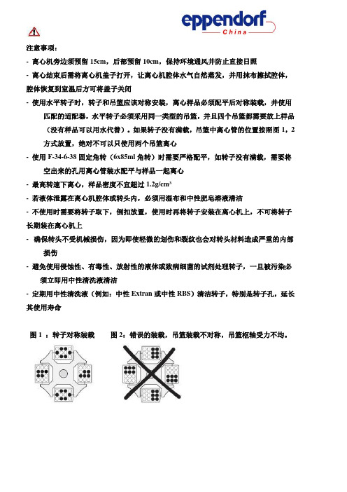
- 使用水平转子时,转子和吊篮应该对称安装,离心样品必须配平后对称装载,并使用匹配的适配器,水平转子必须采用同一类型的吊篮,并且四个吊篮都需要放上样品(没有样品可以用水代替)。
如果转子没有满载,吊篮中离心管的位置按照图1,2方式放置,绝对不可以只使用两个吊篮离心
- 使用F-34-6-38固定角转(6x85ml角转)时需要严格配平,如转子没有满载,需要将空出来的孔用离心管装水配平与样品一起离心
- 最高转速下离心,样品密度不宜超过1.2g/cm3
- 若液体泄露在离心机腔体或转头内,必须用湿布和中性肥皂溶液清洁
- 不使用时需要将转子取下,倒扣放置,使用时再将转子安装在离心机上,不可将转子长期装在离心机上
- 确保转头不受机械损伤,因为即使轻微的划伤和裂纹也会对转头材料造成严重的内部损伤
- 避免使用侵蚀性、有毒性、放射性的液体或致病细菌的试剂处理转子,一旦被污染必须立即用中性清洗液清洁
- 定期用中性清洗液(例如:中性Extran或中性RBS)清洁转子,特别是转子孔,延长其使用寿命
图1 :转子对称装载图2:错误的装载,吊篮装载不对称,吊篮枢轴受力不均。

Version 3.0.32016.06.09Instruction manualTemperature transducersAR550, AR553, AR580, AR581APAR - TRADE OFFICE05-090Raszyn, ul Gałczyńskiego 6Tel.22 853-48-56, 22 853-49-30, 22 101-27-31 E-mail:******************Internet:www.apar.plThank you for choosing our product.This manual will facilitate proper operation, safe useand full utilization of this device.Thoroughly read and understand this instruction manual beforecommencing installation and start-up.Should you have any additional questions, feel free to contact our technical advisers.TABLE OF CONTENTS1. SAFETY RULES (3)2. INSTALLATION RECOMMENDATIONS (3)3. GENERAL SPECIFICATION OF TRANSDUCERS (3)4. TECHNICAL DATA (4)5. HOUSING DIMENSIONS AND INSTALLATION SPECIFICATION (5)6. DESCRIPTION OF THE TERMINAL BLOCK AND ELECTRICALCONNECTIONS (5)7. CONNECTORS – ARRANGEMENT AND DESCRIPTION (5)8. PROGRAMMING CONFIGURATION PARAMETERS (6)9. OUTPUT CONFIGURATION (7)10. INDICATION OF MEASURING ERRORS (7)11. NOTES (7)12. TRANSDUCER CONNECTION METHODS (8)The manufacturer reserves the right to modify the device design and software without degrading technical parameters.1. SAFETY RULESn read this instruction manual thoroughly before commencing to use this device n before switching on the power supply, make sure that all cables are appropriately connected to avoid device damage n ensure suitable operating conditions in line with the device specification (supply voltage, humidity, temperature)n switch off power supply before attempting any modification of connected cables2. INSTALLATION RECOMMENDATIONSThe device has been designed to ensure a suitable level of immunity to the majority of disturbances that can occur in an industrial environment. In environments where the level of interference is unknown it is recommended to use the following measures preventing the potential interference of instrument operation:n do not supply the voltage from the same lines as high power devices without using appropriate line filters n use screened supply, sensor and signal cables, the screens should be earthed on one end only as close to the instrument as possible n uavoid laying supply and signal cables directly next to and in parallel to electrical power cables and supply cables n it is recommended to twist signal cables in pairs n in the case of resistance sensors with 3-cable connections identical cables should be used n avoid installing the instrument in proximity to remotely controlled devices, electromagnetic measuring instruments, high power loads, loads with phase or group power control and other devices generating impulse interference n earth or neutrally ground metal bars on which bar instruments are mounted3 . GENERAL SPECIFICATION OF TRANSDUCERSn linear processing of the measured temperature to a current or voltage signal n universal input :- thermoresistance ... Pt100- thermocouple ......... J, K, S, N, E n n analogue input proportional to the measured temperature- current 4÷20mA or 20÷4mA (2-cable with current loop supply) or - voltage 0÷10Vdc (3-cable)n 581 - current output only n housing- AR580, AR581 - for installing on a TS35 bar (DIN bar)- AR550, AR553 - industrial IP65, 64x58x35 mm n processing range, input type and other parameters configured using the AR950 programmer or the AR956 programming set n exceeded processing range or sensor error signalled with a LED n high accuracy and immunity to interferenceCAUTION:When configuring transducer parameters using the AR956 programmer, set the following transmission parameters in ARSOFT-CFG WZ1 options:- COM port number: specified by Windows after the AR956 driver is installed, go to “Device Manager” group “Ports (COM & LPT)”, see “Quick start programmers AR955 and AR956”- transmission rate (bit/s) 2400 bit/s - MODBUS address = 1A detailed description of configuration parameters can be found in Chapter 8 (page 6).AR553 in an AR550 model with an integrated Pt100 sensorAR4. TECHNICAL DATAUniversal input (programmed with :i n P parameter)measuring range- Pt100 (3- or 2-cable) .......................................................-100 ÷ 850 °C, AR553: -30 ÷ 60°C - thermocouple J ............................................................... -5 ÷ 800°C - thermocouple K .............................................................. -5 ÷ 1200°C - thermocouple S .............................................................. -5 ÷ 1600°C - thermocouple N .............................................................. -5 ÷ 1300°C - thermocouple E .............................................................. -5 ÷ 700°C Cold ends temperature compensation ............................automatic or fixed - programmed with parameters c J t Y and c J t E ................see chapter 8, Table 1Lead resistance for Pt100 ..................................................Rd < 25 - each line with 3-cable connection Pt100 resistance input current Processing range (programmable) .....................................within the input measuring range - processing range minimum width ...................................40°C - measuring resolution ......................................................0,1 °CCurrent output (programmable) .........................................4÷20 mA, 20÷4 mA- load characteristics .........................................................Robc < (Uzas-10V) / 21mA < 1238 m A - maximum resolution .......................................................2m A - nonlinearity .....................................................................< 0,04%Voltage output (programmable) ..........................................0÷10 lub 10÷0 Vdc- load characteristics .........................................................Iobc < 4mA (Robc > 2500 )- rmaximum resolution .......................................................1,25mV - nonlinearity ......................................................................< 0,04%Offset and slope correction ...............................................parameters c A L o (zero offset) and c A L G (sensitivity)Processing intrinsic error (25°C)- for Pt100 input .................................................................< 0,2% of the full measuring range - for thermocouple input .....................................................< 0,3% of the full measuring range - processing resolution error (%) .......................................± 0,1°C x 100 / processing range [°C]Additional errors- cold ends temperature compensation ............................< 2°C (thermocouple inputs only) - cables resistance compensation .....................................< 0,1% Pt100 input measuring range - environment temperature variation .................................< 0,01 % measuring range / °C Rated operating environment- supply (+Vz) - transducer with current output .................10÷36Vdc (>10[V]+Robc[]x0.021[A]) - supply (+Vz) - transducer with voltage output ................18÷36Vdc , Iobc < 4mA - operating temperature and relative humidity rangeAR580, AR581 ....................................................... 0÷60°C, 0÷ 90%RH (no condensation)AR550, AR553 .......................................................-30÷60°C, 0÷100%RH (no condensation)Response time (10÷90%) .....................................................programmable within range 350÷1600 ms Indication of detected errors- optical ..............................................................................red LED- current output signal ........................................................3,8 or 21 mA - voltage output signal .......................................................10,6 VHousing AR580 for TS35 bar (MODULBOX 1MH53) ...............dimensions 18x90x58 mm ~20g Housing AR581 for TS35 bar (GUIDEBOX COMPACT) ...........dimensions ~20g ~100g Electromagnetic compatibility (EMC)- immunity : wg normy PN-EN 61000-6-2:2002(U) - emissivity : wg normy PN-EN 61000-6-4:2002(U)Factory setting ....................................................................see Chapter 8, Table 1CAUTION - programmable parameters can be configured with the AR950 programmer or the AR956 programming set- programming port in AR550 and AR553 can be accessed after the face cover is removedW .........................................~300 m AW - output current resolutions ...............................................16000[] / (processing range [°C])W - output voltage resolutions ...............................................10000[mV] / (processing range [°C])W , weight - protection rating ............................................................IP40 (housing), IP20 (terminals)6,2x76,9x99,1 mm, weight - protection rating ............................................................IP40 (housing), IP20 (terminals)Housing AR550, AR553 (industrial) ...................................dimensions 64x58x35mm, weight - protection rating ............................................................IP655. HOUSING DIMENSIONS AND INSTALLATION SPECIFICATION AR580, AR581AR580 - MODULBOX 1MH53 ...........18x90x58 mm AR581 - GUIDEBOX COMPACT ....... Installation on bar ............................TS35 (DIN EN 50022-35) Connecting loads and supply ........screw terminalsAR550, AR553 (figure in Chapter 7)Dimensions ......................................64x58x35mm 6,2x76,9x99,1 mmMounting holes ................................2 x Φ4,3mmMaterial .............................................policarbonate, IP657. CONNECTORS – ARRANGEMENT AND DESCRIPTIONCAUTION :Connecting devices other than AR950 or AR956 programmer can cause permanent damage to the connected device and to the transducersprogramming ports LEDsAR580AR550, AR553inside with face cover removed832145AR581AR580AR5816. DESCRIPTION OF THE TERMINAL BLOCK AND ELECTRICAL CONNECTIONSterminals descriptions 1-2-3 Pt100 input, 2- or 3-wire 2-3 termocouple input TC (J, K, S, N, E) 4 supply input +Vz 5 4÷20mA current or 0÷10Vdc voltage output 6 voltage output ground+V z OUT GND00w )w )AR581 - current output only8. PROGRAMMING CONFIGURATION PARAMETERSAll the configuration parameters of the device are stored in the non-volatile internal memory.When the device is switched on for the first time, an error may occur due to the lack of a sensor or the fact that the sensor that is connected is not one that is factory-programmed. In such a situation, the appropriate sensor or analog signal should be connected or the parameter configuration must be performed.Methods of parameter configuration via the PR socket (accessible by opening the transparent front cover):1. Use the AR956 programmer and the ARSOFT-CFG software to:-connect the device to a computer port and to start and configure the ARSOFT-CFG application -after the connection has been established, the current measured value is displayed in the window of the software-setting and viewing of the device parameters is possible in the parameter configuration window -new parameter values must be approved with the Approve changes button-the current configuration can be saved in a file or set using values read from a file-Disconnect device button (ARSOFT-CFG)-in the event of no response:-in the Program options check the configuration of the port and the MODBUS address of the device (transmission speed 2,400 bit/s, MODBUS address=1)-make sure that the serial port drivers in the computer have been properly installed for the AR956 programmer-disconnect for a few seconds and then reconnect the AR956 programmer -restart the computer- if the AR955 programmer is used instead of the AR956 programmer, connect the power supply voltage to the transducer (put it in the current loop)2. Use the autonomous AR950 programmer to:-connect the power supply voltage to the transducer;-use the cable included in the set to connect the AR950 programmer to the device being configured (an AR5xx series transducer);-the programmer can be connected both before the power supply is switched on and during operation of the device;-enter the configuration parameters programming mode by pressing (for about 2 s) the CONF button until the message briefly appears on the display and then the mnemonic name of the first parameter is displayed ( ); by pressing the button, you can move to the next parameter, and by pressing the button - to the previous parameter ( …); a list of configuration parameters can be found in the user instruction of the device being configured;-in order to change or view the value of the current parameter, press SET (edition of the parameter);-by using or , you can change the value of the current parameter;-by pressing SET again, you can save the edited value and return to the parameter name display (e.g. );-in the parameter edition mode, by pressing ESC for a short time, you can cancel the changes and return to the parameter name display mode;-you can exit the configuration parameters programming mode by pressing the ESC button for a long time (approx. 1 s); otherwise, the mode is switched off after approx. 2 minutes;-in the normal mode, the measured value is displayed;Detailed information can be found in the user instruction of the AR950 programmer.In the event of indications different than the actual value of the input signal, the zero and the sensitivity of a sensor can be tuned: parameters 7: (zero offset ) and 8: (sensitivity).In order to restore the default settings, use the file with the default configuration in ARSOFT-CFG software.C o n F i n P :i n P F i L t :d o t F i L t c A L o c A L G11. NOTES10. INDICATION OF MEASURING ERRORSThe transducer detects the following measuring errors:- low or high processing range exceeded- connected sensor differs from the one set in configuration parameters - sensor circuit damaged Indication of measuring errors:- LED flashes9. OUTPUT CONFIGURATIONInput signal is directly proportional to the measured signal within the range set with parameters 5: r b o t and 6: r t o P . Figures below present the principle of operation of the analogue output.Remarks: (1) - dla F i L t =2 response time is about 0,35s, for F i L t =15 about 1,6s. A higher filtering level corresponds to a smoother measurement value and longer response time(2) - this applies to displaying data on the AR950 programmerReverse characteristics can be obtained by setting r b o t > r t o p for AR553: r b o t = -30.0, r t o p = 60.0- Pt100 temperature sensor connected to terminals 1, 2 and 3, thermocouples to terminals 2 and 3 - supply cable to terminal +Vs (4)- instrument current or voltage input cable to terminal OUT (5)12.1. Connecting the sensor, power supply and output of a 2-cable transducer(transducer supplied from the instrument)meter or controllermeter or controller- Pt100 temperature sensor connected to terminals 1, 2 and 3, thermocouples to terminals 2 and 3- supply cable to terminal +Vs (4)- instrument measuring ground cable to terminal GND (6)- instrument current or voltage input cable to terminal OUT (5)12.3. Connecting the sensor, power supply and output of a 3-cable transducer(transducer supplied from the instrument)- Pt100 temperature sensor connected to terminals 1, 2 and 3, thermocouples to terminals 2 and 3- power supply cable +24V to terminal +Vs (4)- power supply cable -24V to instrument measuring ground - instrument current or voltage output cable to terminal OUT (5)12.2. Connecting the sensor, power supply and output of a 2-cable transducer(with an external power supply)meter or controller- Pt100 temperature sensor connected to terminals 1, 2 and 3, thermocouples to terminals 2 and 3- power supply cable +24V to terminal +Vs (4)- power supply cable -24V to terminal GND (6), then to instrument ground - instrument current or voltage input cable to terminal OUT (5)12.4. Connecting the sensor, power supply and output of a 3-cable transducer(with an external power supply)meter or controller12. TRANSDUCER CONNECTION METHODS。
CloudEngine 5800 Series Switches V200R005C00Product DescriptionIssue01Date2018-04-23Copyright © Huawei Technologies Co., Ltd. 2018. All rights reserved.No part of this document may be reproduced or transmitted in any form or by any means without prior written consent of Huawei Technologies Co., Ltd.Trademarks and Permissionsand other Huawei trademarks are trademarks of Huawei Technologies Co., Ltd.All other trademarks and trade names mentioned in this document are the property of their respective holders.NoticeThe purchased products, services and features are stipulated by the contract made between Huawei and the customer. All or part of the products, services and features described in this document may not be within the purchase scope or the usage scope. Unless otherwise specified in the contract, all statements, information, and recommendations in this document are provided "AS IS" without warranties, guarantees or representations of any kind, either express or implied.The information in this document is subject to change without notice. Every effort has been made in the preparation of this document to ensure accuracy of the contents, but all statements, information, and recommendations in this document do not constitute a warranty of any kind, express or implied.Huawei Technologies Co., Ltd.Address:Huawei Industrial BaseBantian, LonggangShenzhen 518129People's Republic of ChinaWebsite:About This DocumentIntended AudienceThis document is intended for network engineers responsible for network design anddeployment. You should understand your network well, including the network topology andservice requirements.Symbol ConventionsThe symbols that may be found in this document are defined as follows.Mappings between Product Software Versions and NMS VersionsThe mappings between product software versions and NMS versions are as follows.Mappings between Product Software Versions and Controller VersionsThe mappings between product software versions and Controller versions are as follows.Product Description ContentsContentsAbout This Document (ii)1 Product and Version Mapping (1)2 Product Overview (2)3 Product Appearance (3)4 Typical Applications (8)4.1 Data Center Applications (8)4.2 Campus Network Applications (9)5 Product Features (11)5.1 Feature List (11)5.2 Performance Specifications (18)Product Description 1 Product and Version Mapping1 Product and Version MappingTable 1-1 lists mappings between CloudEngine 5800 series switches and versions.Table 1-1 Product and version mapping2 Product Overview Huawei CloudEngine 5800 (CE5800 for short) series switches are next-generation, high-density gigabit Ethernet switches designed for data centers and high-end campus networks. CE5800 series switches have an advanced hardware architecture design with the industry's highest density of GE access ports. They are the industry's first gigabit access switches that provide 40GE uplink ports. Using the Huawei VRP8 software platform, CE5800 switches support Transparent Interconnection of Lots of Links (TRILL) and have a high stacking capability (up to 16-member switches in a stack system). In addition, the airflow direction (front-to-back or back-to-front) can be changed. CE5800 switches can work with CE12800/ CE8800/CE7800/CE6800 switches to build an elastic, virtualized, high-quality fabric that meets the requirements of cloud-computing data centers.CE5800 switches can function as GE access switches with high-density ports on data center networks to help enterprises and carriers build a scalable data center network platform for cloud computing. They can also be used as aggregation or access switches on enterprise campus networks.3 Product AppearanceThis section only briefly describes switch appearances and key hardware parameters. For detailedhardware information, see the Hardware Description.CE5810Figure 3-1 and Figure 3-2 show appearances of the CE5810-24T4S-EI and CE5810-48T4S-EI respectively.Figure 3-1 Appearance of the CE5810-24T4S-EIFigure 3-2Appearance of the CE5810-48T4S-EITable 3-1 CE5810 key hardware parametersCE5850Figure 3-3, Figure 3-4, Figure 3-5, and Figure 3-6 show appearances of theCE5850-48T4S2Q-EI, CE5850-48T4S2Q-HI, CE5855-24T4S2Q-EI, and CE5855-48T4S2Q-EI respectively.Figure 3-3 Appearance of the CE5850-48T4S2Q-EIFigure 3-4 Appearance of the CE5850-48T4S2Q-HIFigure 3-5 Appearance of the CE5855-24T4S2Q-EIFigure 3-6Appearance of the CE5855-48T4S2Q-EITable 3-2 CE5850 key hardware parameters4 Typical Applications4.1 Data Center ApplicationsOn a typical data center network, CE12800/CE8800/CE7800 switches work as core switches,whereas CE8800/CE6800/CE5800 switches work as access switches and connect to the coreswitches using 100GE/40GE/25GE/10GE ports. The switches use VXLAN and other fabricprotocols to establish a non-blocking large Layer 2 network, which allows large-scale VMmigrations and flexible service deployments.Figure 4-1 Typical application of CE series switches in a data center4.2 Campus Network ApplicationsOn a typical campus network, multiple CE12800/CE8800/CE7800 switches are virtualizedinto a logical core switch using CSS or iStack technology. Multiple CE8800/CE7800/CE6800switches at the aggregation layer form a logical switch using iStack technology. CSS andiStack improve network reliability and simplify network management. At the access layer,CE6800/CE5800 switches are virtualized using technologies such as SVF and M-LAG toprovide high-density line-rate ports.Figure 4-2 Typical application of CE series switches on a campus network5 Product Features5.1 Feature ListTable 5-1 lists the main features supported by the CE5800.Table 5-1 Main features supported by the CE58005.2 Performance SpecificationsFor the product specifications, log in to Huawei official website to download the productbrochure or product feature list for channel (if your account is unauthorized, contact Huaweilocal office).。
HP A5810-48G Switch Data sheetProduct overviewThe HP A5810-48G Switch delivers unparalleled QoS across 48 10/100/1000Base-T Ethernet ports, two multiplex Gigabit Ethernet (GbE) combination SFP ports, and two 10-GbE SFP+ ports for the most demanding enterprise network environments.Key featuresHigh performance for core and distribution "Flex chassis": modular/stackable in onePowerful IPv4/IPv6 ACL/QoS/VoQPowerful buffer capability—24M bufferingRedundant, hot-swappable power supplies, fansFeatures and benefitsManagement•Remote configuration and management: is available through a secure Web browser or a command-line interface (CLI)•IEEE 802.1ab LLDP discovery: advertises and receives management information from adjacent devices on a network•USB support:–File copy: allows users to copy switch files toand from a USB flash drive•DHCP options: client allows automatic setting of IP address•sFlow: provides scalable, ASIC-based, network monitoring and accounting; this allows network operators to gather a variety of sophisticated network statistics and information for capacity planning and real-time network monitoring purposes •SNMPv1, v2c, and v3: facilitate centralized discovery, monitoring, and secure management of networking devicesConnectivity•Auto-MDIX: automatically adjusts forstraight-through or crossover cables on all 10/100 and 10/100/1000 ports•Jumbo frames: on Gigabit and 10-Gigabit ports, allow high-performance remote backup and disaster-recovery services•High-density port connectivity: provides10/100/1000 port configurations up to 80 ports, and an Intelligent Resilient Framework (IRF) stack of up to 576 10/100/1000 portsPerformance•Hardware-based wire-speed access control lists (ACLs): feature-rich ACL implementation (TCAM based) helps ensure high levels of security and ease of administration without impacting network performanceManageability•RMON (remote monitoring): provides advanced monitoring and reporting capabilities for statistics, history, alarms, and events•Web interface: allows configuration of the switch from any Web browser on the network•Multiple configuration files: allow multiple configuration files to be stored to flash image •Troubleshooting: ingress and egress port monitoring enable network problem solvingLayer 2 switching•16K MAC address table: provides access to many Layer 2 devices•4094 port-based VLANs: provide security between workgroups•Gigabit Ethernet port aggregation: allows grouping of ports to increase overall data throughput to a remote device•10 GbE port aggregation: allows grouping of ports to increase overall data throughput to a remote device•Spanning Tree/MSTP, RSTP, and STP Root Guard: prevent network loopsLayer 3 services•Address Resolution Protocol (ARP): determines the MAC address of another IP host in the same subnet; supports static ARPs; gratuitous ARP allows detection of duplicate IP addresses; proxy ARP allows normal ARP operation between subnets or when subnets are separated by a Layer 2 networkLayer 3 routing•Layer 3 IP routing:–Static IP routing: provides basic routing(supporting up to 1K static routes); allows manual configuration of routingSecurity•Port security: allows access only to specified MAC addresses, which can be learned or specified by the administrator•Advanced processor queuing mechanism: helps prevent denial-of-service (DoS) attacks, while DHCP snooping helps ensure that devices can only receive an IP address from a legitimate DHCP server on the network•IEEE 802.1X-based dynamic delivery of QoS, ACLs, and VLANs: allows complete control over user network access•MAC-based authentication: allows or denies access to the switch based on client MAC address•IP source guard: helps prevent IP spoofing attacks•HTTPS management: provides secure Web management•RADIUS/HWTACACS: eases switch managementsecurity administration by using a passwordauthentication server•Secure Shell (SSHv2): encrypts all transmitteddata for secure, remote command-line interface (CLI)access over IP networksConvergence•LLDP-MED: is a standard extension thatautomatically configures network devices, includingLLDP-capable IP phonesMonitor and diagnostics•Port mirroring: enables traffic on a port to besimultaneously sent to a network analyzer formonitoringAdditional information•Green IT and power: use the latest advances insilicon development, shut off unused ports, and usevariable-speed fans to improve power efficiencyWarranty and support•Lifetime warranty: for as long as you own theproduct with advance replacement andnext-business-day delivery (available in mostcountries)*•Electronic and telephone support: limitedelectronic and telephone support is available fromHP; refer to /networking/warranty fordetails on the support provided and the periodduring which support is available•Software releases: refer to/networking/warranty for details onthe software releases provided and the periodduring which software releases are available foryour product(s)*Hardware warranty replacement for as long as you own the product, with next business day advance replacement (available in most countries) with a five-year hardware warranty replacement for the disk drive included with HP AllianceONE Services zl Module, HP Threat Management Services zl Module, HP PCM+ Agent with AllianceONE Services zlSpecificationsHP A5810-48G Switch (JF242A)Ports48 RJ-45 auto-negotiating 10/100/1000 ports (IEEE 802.3 Type 10Base-T, IEEE 802.3u Type 100Base-TX, IEEE 802.3ab Type 1000Base-T)2 SFP 100/1000 Mbps ports2 SFP+ fixed 1000/10000 SFP+ ports; Duplex: full only1 RJ-45 serial console portPower supplies 2 power-supply slots1 minimum power-supplies required (ordered separately)Physical characteristicsDimensions16.54(d) x 17.32(w) x 1.72(h) in. (42 x 44 x 4.36 cm) (1U height)Weight17.64 lb. (8 kg)Memory and processor512 MB SDRAM, 512 MB flash; packet buffer size: 24 MBMounting Mounts in EIA-standard 19 in. telco rack or equipment cabinet (hardware included)PerformanceThroughput up to 101 million ppsRouting/Switching capacity136 GbpsMAC address table size16,000 entriesEnvironmentOperating temperature32°F to 113°F (0°C to 45°C)Operating relative humidity10% to 90%, non-condensingElectrical characteristicsMaximum heat dissipation614 BTU/hr (647.77 kJ/hr)Voltage100-120 / 200-240 VACFrequency50 / 60 HzSafety UL 60950-1; EN 60825-1 Safety of Laser Products-Part 1; EN 60825-2 Safety of Laser Products-Part 2; IEC 60950-1; CAN/CSA-C22.2 No. 60950-1; Anatel;ULAR; GOST; EN 60950-1/A11; FDA 21 CFR Subchapter J; NOM; ROHS ComplianceEmissions VCCI Class A; EN 55022 Class A; ICES-003 Class A; ANSI C63.4 2003; AS/NZS CISPR22 Class A; EN 61000-3-2:2006; EN 61000-3-3:1995+A1:2001+A2:2005; EMC Directive 2004/108/EC; FCC (CFR 47, Part 15) Class AImmunityGeneric ETSI EN 300 386 V1.3.3EN EN 55024:1998+ A1:2001 + A2:2003ESD EN 61000-4-2; IEC 61000-4-2Radiated EN 61000-4-3; IEC 61000-4-3EFT/Burst EN 61000-4-4; IEC 61000-4-4Surge EN 61000-4-5; IEC 61000-4-5Conducted EN 61000-4-6; IEC 61000-4-6Power frequency magnetic field IEC 61000-4-8; EN 61000-4-8Voltage dips and interruptions EN 61000-4-11; IEC 61000-4-11Harmonics EN 61000-3-2, IEC 61000-3-2Flicker EN 61000-3-3, IEC 61000-3-3Management IMC - Intelligent Management Center; command-line interface; Web browser; out-of-band management; SNMP Manager; Telnet; HTTPS; RMON1; FTPNotes A5810 switch provides a power module when shipped. Customer can select two power modules to implement 1+1 power supply redundancy.Services3-year, 4-hour onsite, 13x5 coverage for hardware (UV882E)3-year, 4-hour onsite, 24x7 coverage for hardware (UV885E)3-year, 4-hour onsite, 24x7 coverage for hardware, 24x7 software phone support (UV888E)3-year, 24x7 SW phone support, software updates (UV891E)4-year, 4-hour onsite, 13x5 coverage for hardware (UV883E)4-year, 4-hour onsite, 24x7 coverage for hardware (UV886E)4-year, 4-hour onsite, 24x7 coverage for hardware, 24x7 software phone (UV889E)4-year, 24x7 SW phone support, software updates (UV892E)5-year, 4-hour onsite, 13x5 coverage for hardware (UV884E)5-year, 4-hour onsite, 24x7 coverage for hardware (UV887E)5-year, 4-hour onsite, 24x7 coverage for hardware, 24x7 software phone (UV890E)5-year, 24x7 SW phone support, software updates (UV893E)3 Yr 6 hr Call-to-Repair Onsite (UW969E)4 Yr 6 hr Call-to-Repair Onsite (UW970E)5 Yr6 hr Call-to-Repair Onsite (UW971E)Specifications (continued)HP A5810-48G Switch (JF242A)Refer to the HP website at /networking/services for details on the service-level descriptions and product numbers. For details about services andresponse times in your area, please contact your local HP sales office.Standards and protocols General protocolsIEEE 802.1ag Service Layer OAMIEEE 802.1D MAC BridgesIEEE 802.1p PriorityIEEE 802.1Q VLANsIEEE 802.1s (MSTP)IEEE 802.1v VLAN classification by Protocol andPortIEEE 802.1w Rapid Reconfiguration of SpanningTreeIEEE 802.1X PAEIEEE 802.3ad Link Aggregation Control Protocol(LACP)IEEE 802.3ae 10-Gigabit EthernetIEEE 802.3x Flow ControlRFC 768 UDPRFC 792 ICMPRFC 793 TCPRFC 826 ARPRFC 854 TELNETRFC 925 Multi-LAN Address ResolutionRFC 951 BOOTPRFC 1519 CIDRRFC 1542 BOOTP ExtensionsRFC 2131 DHCPRFC 3576 Ext to RADIUS (CoA only)RFC 4675 RADIUS VLAN & Priority MIBsIEEE8021-PAE-MIBIEEE8023-LAG-MIBRFC 1213 MIB IIRFC 1493 Bridge MIBRFC 2011 SNMPv2 MIB for IPRFC 2013 SNMPv2 MIB for UDPRFC 2233 Interface MIBRFC 2273 SNMP-NOTIFICATION-MIBRFC 2571 SNMP Framework MIBRFC 2572 SNMP-MPD MIBRFC 2573 SNMP-Notification MIBRFC 2618 RADIUS Client MIBRFC 2620 RADIUS Accounting MIBRFC 2665 Ethernet-Like-MIBRFC 2674 802.1p and IEEE 802.1Q Bridge MIBRFC 2688 MAU-MIBRFC 2819 RMON MIBRFC 2925 Ping MIBRFC 3414 SNMP-User based-SM MIBRFC 3415 SNMP-View based-ACM MIBRFC 3418 MIB for SNMPv3RFC 3826 AES for SNMP's USM MIBRFC 4133 Entity MIB (Version 3)LLDP-EXT-DOT1-MIBLLDP-EXT-DOT3-MIBLLDP-MIBNetwork managementIEEE 802.1AB Link Layer Discovery Protocol (LLDP)RFC 2819 Four groups of RMON: 1 (statistics), 2(history), 3 (alarm) and 9 (events)RFC 3176 sFlowANSI/TIA-1057 LLDP Media Endpoint Discovery(LLDP-MED)SNMPv1/v2c/v3SecurityIEEE 802.1X Port Based Network Access ControlRFC 1492 TACACS+RFC 2865 RADIUS (client only)RFC 2866 RADIUS AccountingSecure Sockets Layer (SSL)SSHv2 Secure ShellHP A5810-48G Switch accessories© Copyright 2010 Hewlett-Packard Development Company, L.P. The information contained herein is subject to change without notice. The only warranties for HP products and services are set forth in the express warranty statements accompanying such products and services. Nothing herein should be construed as constituting an To learn more, visit /networkingTransceiversHP X124 1G SFP LC LH40 1310nm Transceiver (JD061A)HP X120 1G SFP LC LH40 1550nm Transceiver (JD062A)HP X125 1G SFP LC LH70 Transceiver (JD063B)HP X110 100M SFP LC LH40 Transceiver (JD090A)HP X110 100M SFP LC LH80 Transceiver (JD091A)HP X130 SFP+ LC SR Transceiver (JD092B)HP X130 SFP+ LC LRM Transceiver (JD093B)HP X130 SFP+ LC LR Transceiver (JD094B)HP X110 100M SFP LC FX Transceiver (JD102B)HP X125 1G SFP LC SX Transceiver (JD118B)HP X120 1G SFP LC LX Transceiver (JD119B)HP X110 100M SFP LC LX Transceiver (JD120B)HP X240 SFP+ SFP+ 0.65 m Direct Attach Cable (JD095B)HP X240 SFP+ SFP+ 1.2 m Direct Attach Cable (JD096B)HP X240 SFP+ SFP+ 3 m Direct Attach Cable (JD097B)CablesNEW HP 0.5 m PremierFlex OM3+ LC/LC Optical Cable(BK837A)Power SupplyHP A5800 300W AC Power Supply (JC087A)Fan TrayHP A5800 1RU Spare Fan Assembly (JC098A)。
Wide-range power supplies7XV5810 0BA00 (24 V)7XV5810 0CA00 (5 V)Operating InstructionsC53000-B1140-C602-1Seite 2 von 20 Operating Instructions 7XV5810 0xA00Table of content1 GENERAL INSTRUCTIONS (3)1.1 Safety Notes (4)1.2 General hints (5)1.3 Customer Support (5)1.4 Statement of Conformity (6)1.5 Further Standards (6)1.6 Used Symbols (6)1.7 Exclusion of liability (7)1.8 Copyright (7)1.9 Operating Instructions (8)1.10 Scope of Application (8)1.11 Description of the functional unit (8)1.12 In case of a short-circuit (8)1.13 Switching off the device (8)1.14 Installation (8)1.15 Connection (9)1.16 Commissioning (9)1.17 Maintenance (10)2 TECHNICAL DATA (11)2.1 Power supply 7XV5810 0BA00 (24 V) (11)2.2 Power supply 7XV5810 0CA00 (5 V) (12)2.3 Combined specifications (13)2.4 Dimension Drawings (18)2.5 Connection terminals 7XV5810-0BA00 (24 V) (19)2.6Connection terminals 7XV5810-0CA00 (5 V)............................................................................19 2.7 Ordering Data . (20)FiguresFigure 1: Dimension Drawings (in mm) (18)TablesTable 1: Connection terminals for the 24 V wide-range power supply ................................................. 19 Table 2: Connection terminals for the 5 V wide-range power supply ................................................... 19 Table 3: Ordering Data of the wide-range power supplies .. (20)C53000-B1100-C602-1 7XV5810 0xA00 Operating Instructions Seite 3 von 201 General InstructionsThis manual includes the information required for the normal use of the products described therein. It is intended for technically qualified personnel who has been specially trained or has special knowledge in the fields of protection-,instrumentation-, control-, and automatic control engineering (called automation in the following).The knowledge and the technically correct translation of the safety instructions and warnings included in this manual are a prerequisite for the safe installation and commissioning, as well as for safety during operation and maintenance, of theproduct described. Only qualified personnel, as defined in the following explanation, possess the technical knowledge required to interpret correctly and to put into action for each individual case the safety instructions and warnings given in this document in a general manner.This manual is an integral part of the scope of delivery. However, it cannot take into account every detail on all types of the described product and also every possible case regarding installation, operation or maintenance. If further information is desired or in case special problems should arise, which are not treated adequately in this document, it is possible to obtain additional details from the local Siemens office or from the addresses stated in the back of this manual.Additionally, we point out that the content of this product documentation is not part of or modifies any previous or existing agreement, promise, or legal relationship.All obligations by Siemens result from the respective purchase order which also includes the complete and exclusively valid warranty provision. The contractual warranty regulations are neither extended nor limited by the statements in this document.C53000-B1140-C602-1Seite 4 von 20 Operating Instructions 7XV5810 0xA001.1 Safety NotesThese operating instructions contain notes that are to be complied with for yourpersonal safety as well as to avoid property damages. These notes are marked by a triangular warning symbol and the different degrees of danger are categorized as follows:DangerDisregard of the corresponding precautionary measures willcause death, severe bodily injury or considerable propertydamage.WarningDisregard of the corresponding precautionary measuresmay cause death, severe bodily injury or considerable property damage.AttentionDisregard of the corresponding precautionary measuresmay lead to slight bodily injury or minor property damageNoteShall draw your attention to special information on theproduct, product handling or the corresponding section ofthe documentation.personnelCommissioning and operation of the equipment is to beperformed by qualified personnel only. In the context ofsafety notes in this manual, the term qualified personnelrefers to persons authorized to perform commissioning,grounding and labelling of devices, systems and electricalcircuits.C53000-B1100-C602-1 7XV5810 0xA00 Operating Instructions Seite 5 von 201.2 General hintsThe enclosure must comply with the requirements for thefire protection enclosure according to the standardEN 60950.WarningThis device is designed to be used in enclosures orclosed rooms. Operating the devices outside of the enclosures can lead to electro-magnetic disturbancesand – in case of a defect – to a fire hazard.WarningThe device must be operated only within the scope of itsintended use according to these operating instructionsand in connection with third-party equipment or compounds recommended or accepted by Siemens.Faultless and safe operation of the product requireproper transport, storage, mounting and installation aswell as careful operation and maintenance.1.3 Customer SupportFor any questions concerning your system, please contact your Siemensrepresentative. The Siemens Customer Support Center provides around-the-clock support.Phone: +49 (1805) 24-7000Fax: +49 (1805) 24-2471Internet: E-Mail: **************************C53000-B1140-C602-1Seite 6 von 20Operating Instructions 7XV5810 0xA001.4 Statement of Conformity Low-voltage Directive 2014/35/EUEMC Council Directive 2014/30/EUThis conformity has been established by means of tests conducted bySiemens AG according to the Council Directive in agreement with thegeneric standard EN 60255-26 for the EMC directives, and with the standard EN 61010-1 for the low-voltage directive. 1.5 Further Standards This product is UL-certified, based on the technical data acc. to Standard UL 61010-1, third edition; UL File No.: E228586MeasuringEquipmentE2285861.6 Used SymbolsNr. Symbol Description1 Direct current: IEC 60417-50312Alternating current: IEC 60417-5032 3 Direct and alternating current: IEC 60417-50334Earth (ground) terminal: IEC 60417-5017 5 Protective conductor terminal: IEC 60417-50196Caution, risk of electric shock 7 Caution, risk of danger: ISO 7000-04348Protective Insulation IEC 60417-5172 Safety Class II devices 9 Guideline 2002/96/EC for electrical and electronic old devicesC53000-B1100-C602-1 7XV5810 0xA00 Operating Instructions Seite 7 von 201.7 Exclusion of liabilityThe contents of this document have been reviewed on their compliance with thehardware and software described therein. Yet, deviations cannot be excluded, so that we cannot guarantee full compliance. The specifications in this document are,however, reviewed at regular intervals. Necessary corrections will be included in the next edition. You are invited to send us your suggestions for improvement.1.8 CopyrightCopyright Siemens AG 2018. All rights reserved.Transmission or reproduction of this document, as well as the use and forwarding of its contents is not permitted without express written authority. Offenders will be liable for damages. All rights, including rights created by patent grant or registration of a utility model or design, are reserved.Subject to technical changes without notice.C53000-B1140-C602-1Seite 8 von 20 Operating Instructions 7XV5810 0xA001.9 Operating Instructions1.10 Scope of ApplicationThe switched mode Wide-range power supply unit has a universal scope ofapplication due to its extremely wide input voltage range. The power supply unit is designed for low power consumers (output power up to 3W) that require a mains buffering time of more than 50ms. The output is short-circuit proof and stable at no load. The output voltage is monitored and displayed via a pilot LED. If the output voltage falls short by 10% a relay opens and the LED goes out.1.11 Description of the functional unitThe Wide-range power supply unit inside its plastic housing is a hardwired and tested functional unit. It is provided with a clip-on mounting for a DIN EN 50022 top-hat rail 35 mm. Auxiliary power supply, electrical consumer and pilot relay can be safelyconnected via the screw-type terminals. The devices are free of silicone and halogen as well as flame-retardant (UL94-V0).1.12 In case of a short-circuitThe output of the Wide-range power supply unit is short-circuit proof for an unlimited amount of time. In case of a short-circuit longer than 5 seconds the device must be switched off for more than 30 seconds or be operated in open-line operation to be ready for operation again.1.13 Switching off the deviceAfter the switching off of the device and the decrease of the GOK relay, the device must stay off during 3.5 seconds before it can be switched on. If you start the device before this time range of 3.5 seconds, the device must thus stay off during 5 minutes before being able to be switched on again.1.14 Installation∙ The admissible ambient temperature (operation or functional temperature) isto be observed (see technical data, chapter 2).∙ Disregard of the temperature range required for proper function may causemalfunction and failure of the device∙ The wide-range power supply unit must be clipped on a 35 mm top-hat rail(according to DIN EN 50022). It is not admissible to install the device withscrews∙ A spacing of 100 mm before and after the device respectively must beobserved to allow the cooling of the device with the help of the venting slots. ∙ The devices are permitted only for operation within enclosed housing orcabinets or the places of installation are to be accessible only for qualifiedpersonnel.C53000-B1100-C602-1 7XV5810 0xA00 Operating Instructions Seite 9 von 201.15 Connection∙ The connection of the supply voltage is to be carried out according toVDE0100 and VDE0160. The auxiliary supply of the device is to be provided with an external disconnector (switch) for the safety isolation of the powersupply and with a safety device (fuse), 2 AT or 4 AT.∙ The external disconnector is to be labelled accordingly. A safety cutout canpossibly act in both functions.∙ Recommended stripping length: 5 mm.∙ The output voltage of the power supply conducted to the consumer must bedone with cables that are isolated twice or are separated from the networkcables.1.16 Commissioning∙Check whether the operation data comply with the values on the rating plate. ∙Do not make any changes at the device. ∙Clip the wide-range power supply on the top–hat rail with the help of clip-on mounting. ∙Connect the auxiliary power to the terminals V aux (see chapter 2.5 und 0). ∙The device is ready for use after switching on the auxiliary power. ∙ The green LED `RUN´ lights up.C53000-B1140-C602-1Seite 10 von 20 Operating Instructions 7XV5810 0xA00 1.17 MaintenanceThe wide-range power supplies require no maintenance. For cleaning, please use a dry and free of fuzz rag.C53000-B1100-C602-12 TechnicalData2.1 Power supply 7XV5810 0BA00 (24 V)InputPower supply (V aux) – Direct-current voltage (DC)24 V to 250 V (±20 %)Ripple allowed for the DC input voltage 15 %Power input 12 WMaximum inrush current at ≤ 110 V < 15 AMaximum inrush current at 220 V to300 V≤ 22 A; after 250 µs: < 5 ADegree of efficiency > 50 % at nominal loadPower supply (V aux) – Alternative current (AC)60 V to 230 V (±20 %),45 Hz to 65 HzHigher harmonics allowed 2 kHzMaximum inrush current at ≤ 115 V < 15 AMaximum inrush current at 230 V ≤ 22 A; after 250 µs: < 5 APower input 25 VAOutputConnection 2-poleterminal Rated output current Max. 250 mABehavior in case of short-circuit: mainsbufferingpermanentPower supply failure At least 50 ms at nominal loadStatus display of the output voltage 1 green operating LEDRated output voltage DC 24 V; Imax = 125 mA(at V aux= DC 24 V to 35 V)DC 24 V; Imax = 250 mA(at V aux = DC 35 V to 250 V or AC 60 V to 230 V)2.2 Power supply 7XV5810 0CA00 (5 V)InputPower supply (V aux) – Direct-current voltage (DC)24 V to 250 V (±20 %)Ripple allowed for the DC input voltage 15 %Power input 8 WMaximum inrush current at ≤ 110 V < 15 AMaximum inrush current at 220 V to≤ 22 A; after 250 µs: < 5 A300 VDegree of efficiency > 50 % at nominal loadPower supply (V aux) – Alternative current (AC)60 V to 230 V (±20 %),45 Hz to 65 HzHigher harmonics allowed 2 kHzMaximum inrush current at ≤ 115 V < 15 AMaximum inrush current at 230 V ≤ 22 A; after 250 µs: < 5 APower input 12 VAOutputterminal Connection 2-poleRated output current 600 mABehavior in case of short-circuit: mainspermanentbufferingPower supply failure At least 50 ms at nominal loadStatus display of the output voltage 1 green operating LEDRated output voltage DC 5 V; Imax = 600 mAC53000-B1100-C602-12.3 Combined specificationsEnvironmental conditions (operate only in rooms)Ambient TemperaturesTemperature recommended during theoperation-5 °C to +55 °C (23 °F to 131 °F)Temperature during the transport and thestorage -25 °C to +70 °C (-13 °F to 158 °F)Humiditymean value per year ≤ 75 % relative humidityMaximum value per year95 % relative humidity on 30 days peryearCondensation during operation Not allowed Condensation during transport andstorageAllowedOther environmental indications Maximum height over sea level 2000 m Degree of pollution 2 Class of protection according to IEC60529IP 20Overvoltage category IIIAlarm relay RelayMSR-Relay, 1 NC (open) contact Potential free 2-pole connector Maximum switching voltage (nominal value):AC 240 V Maximum switching current 5 AMaximum switching capability DC: 50 W at 300 V DC 270 W at 35 V AC 2000 VA Allowed current for contacts 5 AFusesSoldered T2.0 A Exchangeable T1.6 A / AC 250 V / DC 300 VSafetyAcc. to DIN EN 61010 Part 1 Overvoltage category Degree of pollutionFire stability ClassAcc. to UL 94 III 2 V0Insulation testsEN61010IEC 255-5: ANSI/IEEE C37.90.0Voltage test (routine test)- Auxiliary power to fault relay- Auxiliary power to RS232 interface - Fault relay to RS232 interface Surge voltage test (type test)61010-1 3rd edition- Auxiliary power to relay- Auxiliary power to RS232 interface - Fault relay to RS232 interface eachDC 5 kV / 1 s (with bypass capacitors) AC 3,51 kV/50 Hz/1 s(without bypass capacitors)each6,4 kV (peak);1,2 µs /50 µs; 0,5 J;3 pos. und 3 neg. surges inIntervals of 5 sAll circuits, Class III(not on open contacts)EMC Tests on interference emission Standard: EN 50081-1Conducted interference only powersupply voltage,CISPR 22, EN 55022DIN VDE 979 Teil 22 Radio interference field strength CISPR 11, EN 55011DIN VDE 0878 Teil 22 150 kHz to 30 MHz Limit Class ALimit Class A30 MHz to 1000 MHz Limit Class ALimit Class AC53000-B1100-C602-1EMC tests on interference immunity IEC 60255-26 (Product standard)Damped oscillatory wavesIEC 60255-26, IEC 61000-4-18, Class III VDE 0435 part 303, Class IIIElectrostatic discharge (ESD) IEC 60255-26 Class III EN 61000-4-2, Class IIIRadiated electromagnetic fields, amplitude modulated IEC 61000-4-3Radiated electromagnetic fields, pulse modulated IEC 61000-4-3Fast transient disturbances/Burst IEC 61000-4-4, Class IEC 60255-26, Class IV EN 61000-4-4, Class IVFast transient disturbances /Burst IEC 61000-4-4, Class III IEC 60255-26, Class III EN 61000-4-4, Class III100 kHz and 30 surges per minute; Test duration 1 minute 2,5 kV longitudinal voltage; 1 kV transverse voltage6 kV contact discharge 8 kV air discharge, both polarity; 150 pF; Ri = 330 Ohm10 V/m; 80 MHz to 1000MHz; 80% AM; 1 kHz35 V/m, 900 MHz Frequency 200 kHz;Duty cycle 50 % oder Duty cycle 100 %On power supply input 4 kV; 5/50 ns; 5 kHz; Burst duration 15 msRepetition 300 ms; both polarity; Ri = 50 Ohm; test duration: 1 minOn signal lines4 kV; 5/50 ns;5 kHz;Burst duration 15 ms above average Repetition 300 ms; both polarity; Ri = 50 Ohm; test duration 1 minLine conducted HF, amplitude modulated IEC 61000-4-6, EN 61000-6-5Immunity to power frequency magnetic fieldEN 61000-4-8, Class IV 10 V; 150 kHz to 80 MHz;80 % AM; 1 kHz30 A/m, permanent; 300 A/m during 3 s;50 HzMechanical stress testVibration and shock during operationVibrationIEC 60068-2-6IEC 60255-21-1ShockIEC 60068-2-27IEC 60255-21-2, Class 1 Seismic vibrationIEC 60068-3-3IEC 60255-21-3, Class 2 sinusoidal5 Hz to 150 HzAmplitude;+/- 7,5 mm (under 8 Hz): acceleration: 20 m/s2 (2 g) (beyond 8 Hz) Frequency sweep rate 3 (each at 90o)20 cycles per axesemi-sinusoidalacceleration 5 g, duration 11 ms,every 3 shocks in both directions of the 3 axessinusoidal1 Hz to 8 Hz: +8 mmAmplitude (horizontal axe)1 Hz to 8 Hz: +4 mmAmplitude (vertical axe)8 Hz to 35 Hz: 2g acceleration (horizontal axe)8 Hz to 35 Hz: 1g acceleration(vertical axe)Frequency sweep rate 1 octave/min1 cycle in 3 orthogonal axesC53000-B1100-C602-1Vibration and shock during transport and storageVibrationIEC 60068-2-6IEC 60255-21-1, Class 2 ShockIEC 60068-2-27IEC 60255-21-2, Class 1 ShockIEC 60068-2-29IEC 60255-21-2, Class 1 sinusoidal5 Hz to 8 Hz: ± 7,5 mm amplitude;8 Hz to 150 Hz: 2 g acceleration Frequency sweep rate 1 octave/min20 cycles in 3 axes orthogonalsemi-sinusoidalAcceleration 15 g, duration 11 ms, every 3 shocks in both directions of the 3 axes semi sinusoidalAcceleration 10 g, duration 16 ms, every 1000 shocks in both directions of the 3 axesDrawingsFigure 1: Dimension Drawings (in mm)2.5 Connection terminals 7XV5810-0BA00 (24 V)Terminal Description Connection0V Output voltage V A Consumer≤ 6 WFor V aux = 24 V to 35 V, max. 3 W 24V Output voltage U A Consumer≤ 6 WFor V aux > 35 V, max. 6 W1 Voltage control relay K1 1 (break contact)2 Voltage control relay K1 1 (break contact)L1/L+ Power supply V aux AC: L1 DC: L+N/L- Power supply V aux AC: N DC: L-Table 1: Connection terminals for the 24 V wide-range power supply2.6 Connection terminals 7XV5810-0CA00 (5 V)Terminal Description Connection0V Output voltage V A Consumer≤ 3 W≤ 3 W5V Output voltage V A Consumer1 Voltage control relay K1 1 (break contact)2 Voltage control relay K1 1 (break contact)L1/L+ Power supply V aux AC: L1 DC: L+N/L- Power supply V aux AC: N DC: L-Table 2: Connection terminals for the 5 V wide-range power supply2.7 OrderingDataName Ordering-Nr. Wide-range power supply 7 X V 5 8 1 0 - 0 A 0 024 V B5 V CTable 3: Ordering Data of the wide-range power supplies。
离心机 5804/5804 R/5810/5810 R使用手册图1 :5804 / 5810 (非冷冻离心机)显示界面和控制面板图2:5804 R/ 5810 R (冷冻离心机)显示界面和控制面板目录1.简介1.1.包装1.2.开箱1.3.仪器安装2.安全警告与应用限制3.操作3.1.控制键3.2.装载/装卸转子3.3.转子盖F-45-30-113.4.装上转子3.5.屏幕上显示预设时间/转速的常规离心3.6.持续运行3.7.瞬时离心3.8运行中时间变更3.9冷冻(仅对5804R/5810R)3.10预设半径3.11软启动/软停止离心3.12定速记时功能3.13预调程序3.14编辑状态3.15写保护3.16设定定值显示3.17自动转子识别3.18显示已运行时间3.19开关报警信号3.20退出服务程序3.21通过系列界面控制(可选)3.22断电情况下打开机器3.23断流器开关/保险4.保养与清洗4.1.主机4.2.转子4.3.气密型转子4.4.转子消毒4.5.玻璃破损4.6.冷冻离心机5.问题及解决方法6.技术参数1.简介5804/5810 是不带冷冻功能的台式离心机,5804R/5810R是带冷冻功能的台式离心机。
5804/5804R最大样品容量400ml,5810/5810R最大样品容量1600ml。
所有离心机适于医药以及科学研究等领域的实验室科学研究。
在离心机上和此操作手册里多处见到此标记。
注此标记的文字说明包含了安全注意。
第一次使用离心机前仔细阅读安全警告。
在第一次启动5804/5810和5804R/5810R时,请仔细阅读使用手册。
1.1.运输包装1 带冷却风扇的5804/5810R离心机或者是冷冻型5804R/5810R(不包括转子)1 主电源线(欧式插座)1 使用手册1 转子起子1.2 开箱从包装箱取离心机时,首先将仪器整个包装搬至承重桌面最近的位置,尔后需要两个人分别从仪器左右两侧底部接近橡皮脚附近的位置着手,将仪器放置水平桌面。
5810R使用手册离心机5804/5804 R/5810/5810 R使用手册图1 :5804 / 5810 (非冷冻离心机)显示界面和控制面板图2:5804 R/ 5810 R (冷冻离心机)显示界面和控制面板目录1.简介1.1.包装1.2.开箱1.3.仪器安装2.安全警告与应用限制3.操作3.1.控制键3.2.装载/装卸转子3.3.转子盖F-45-30-113.4.装上转子3.5.屏幕上显示预设时间/转速的常规离心3.6.持续运行3.7.瞬时离心3.8运行中时间变更3.9冷冻(仅对5804R/5810R)3.10预设半径3.11软启动/软停止离心3.12定速记时功能3.13预调程序3.14编辑状态3.15写保护3.16设定定值显示3.17自动转子识别3.18显示已运行时间3.19开关报警信号3.20退出服务程序3.21通过系列界面控制(可选)3.22断电情况下打开机器3.23断流器开关/保险4.保养与清洗4.1.主机4.2.转子4.3.气密型转子4.4.转子消毒4.5.玻璃破损4.6.冷冻离心机5.问题及解决方法6.技术参数1.简介5804/5810 是不带冷冻功能的台式离心机,5804R/5810R是带冷冻功能的台式离心机。
5804/5804R最大样品容量400ml,5810/5810R最大样品容量1600ml。
所有离心机适于医药以及科学研究等领域的实验室科学研究。
在离心机上和此操作手册里多处见到此标记。
注此标记的文字说明包含了安全注意。
第一次使用离心机前仔细阅读安全警告。
在第一次启动5804/5810和5804R/5810R时,请仔细阅读使用手册。
1.1.运输包装1 带冷却风扇的5804/5810R离心机或者是冷冻型5804R/5810R(不包括转子)1 主电源线(欧式插座)1 使用手册1 转子起子1.2 开箱从包装箱取离心机时,首先将仪器整个包装搬至承重桌面最近的位置,尔后需要两个人分别从仪器左右两侧底部接近橡皮脚附近的位置着手,将仪器放置水平桌面。
请注意桌面能够承受的重量范围。
如果仪器离桌面较远,请用推车帮助运输。
1.3 仪器安装仅对5804R/5810R适用:为了防止由于运输不当而对压缩机造成损坏,机器安装4小时以后才能开机。
在放置离心机的房子或者是隔壁的房子,在远离离心机的位置一定要安装一个紧急开关。
一旦离心机发生故障,切断离心机的电源。
-将离心机放置于水平,稳固,无共振的工作台。
-周围环境应确保通风并防止直接日晒。
-仪器旁边有15cm空间,仪器后面至少有10cm空间。
-按照EN61010-2-020的标准规则,离心时离心机四周应保证30cm的空隙无杂物以防仪器受损-连接电源时,确保供电电压与频率与仪器铭牌所示相符。
离心机电源插入的插座,要求具备地线。
按一下离心机右侧的电源开关,即可打开离心机。
在离心机的面板上会显示测试运转的各个预定的参数,Open 指示灯打开。
-按Open键离心机的盖子打开。
在启动离心机之前,放入转子,并用提供的转子起子拧紧转子。
转子A-4-81,A-4-81-MTP的包装里有配套转子起子。
安全警告与应用限制为了你自身安全,务必遵守以下条款:转子和转子盖必须拧紧,否则严禁运转。
转子必须对称装载,位置相对的离心管应是同一型号并注入等量试剂。
考虑到机械的稳定性,所有的位置必须采用同一类型的吊篮。
请勿使用有明显腐蚀,损坏痕迹的转子或吊篮。
定期检查附件不要启动没有正确安装或维修的离心机。
当离心机转动时,不要移动或敲打机身。
请使用原装配件或者Eppendorf 公司推荐的附件。
日常维修应由Eppendorf授权的技术人员进行。
5804/5810以及5804R/5810R离心机仅用于特殊应用。
离心机应该在一个无危险品,引燃品的环境中运行,不能用于易爆品或高活性物质的离心。
液体泄露在离心机腔体或转头内,必须用湿布和中性肥皂溶液清洁。
最大转速时,离心液体的密度绝对不能超过1.2g/ml。
5804/5810离心机长时间离心时,样品管的温度会升高,请注意离心管制造商提供的技术参数。
使用有机溶剂(例如:氯仿)会对塑料离心管的稳定性造成不利影响。
当将离心机自寒冷环境移至正常实验室时,应预先在寒冷环境中运转离心机30分钟。
或者至少在实验室中放置3小时使其逐渐变暖,但不能连通电源。
转头是离心机的重要组件,可承受极端机械张力。
铝质转头上的电镀层可使转头免受来自实验室常规化学品的腐蚀。
请确保转头不受机械损伤,即使轻微的划伤和裂纹也会对转头材料造成严重的内部损伤,这种损伤眼睛是不可能见到的。
请避免用侵蚀性的化学品处理转子。
这类物品包括:浓碱和中性碱,浓酸,含有汞、铜和其他重金属离子的溶液,氯碳氢化合物,浓盐溶液。
当操作危险健康的,有毒的,放射性的液体或致病细菌(不包括在RISK GROUP II),请遵守本国的规章制度。
一旦转子被非纯净物质或者侵蚀性试剂污染,转子必须立即用中性清洗液清洁。
这对角度转头的孔和水平转头的吊篮尤其重要。
请定期用中性清洗液(例如:中性Extran或中性RBS)清洁转子,这样将保护转头,延长其使用寿命。
按照EN55011规定,5804/5810以及5804R/5810R 属于A级产品。
在住宅区会发生信号接收干扰。
操作者最好有适当的保护措施。
-以下转子及配套的吊篮具有最长7年的工作寿命,在转子上刻有一个四位数字的生产日期(如10/98=1998年10月生产):A-4-44 5804 730.003 A-4-62-MTP 5810 711.002A-2-DWP 5804 740.009 T-60-11 5804 730.003F-34-6—38 5804 727.002 A-4-81 5810 718.007A-4-62 5810 709.008 A-4-81-MTP 5810 725.003- 透明的转子盖子由PC聚碳酸酯和PP聚丙烯制成,吊篮的盖子由PC制成。
可最长使用3年。
以钟表的形状刻在上面表明生产日期-当离心有机溶剂(如氯仿、苯酚)时气密性盖子的密封力度会降低。
定期检查气密性盖帽以防其变化或开裂。
一旦有裂缝或其他损坏请立即调换。
转子,盖帽或吊篮一旦有化学损伤或机械损坏或者超过其寿命即刻停止使用!* PC=聚碳酸酯PP =聚乙烯3、操作3.1控制键见本手册开始的折叠页。
列出了prog,time,speed 等重要键。
“Bucket” 包括吊篮以及微孔板的吊篮。
3.2装载/装卸转子在使用手册中有各种转子的描述。
安装转子之前,用布清洁转轴以及转孔。
-转子安装到转轴上,旋紧之前,要保证转子的温度和转轴的温度在10度-30度之间-转子安装到转轴上,用配套的转子起子顺时针拧紧转子-拆卸转子时,用配套的转子起子逆时针松开转子-转子单独放置时,最好是放在转子架上(定货号5804 720.008)-请勿使用有明显腐蚀,损坏痕迹的转子或吊篮。
(见第2章安全警告与应用限制)5804/5810以及5804R/5810R离心机有自动转速限制3.3 转子盖子F-45-30-11非气密性的转子F-45-30-11只需轻按即可安装到转子上,无需用起子拧紧3.4装载转子转子和吊篮应该对称安装。
适配器只适用于匹配的离心管。
尽量避免样品管重量间差异以延长离心机的使用寿命和减少不平衡导致的噪音。
关于每一个转子,都提供了相关的信息,提示一个完全装载的吊篮的重量(吊篮包括适配器,离心管,样品或者是微孔板吊篮包括微孔板和样品)(参见应用限制)水平转子只能使用制造商推荐的转子/吊篮/适配器配套组合请检查吊篮是否安装正确和能水平转动考虑到机械稳定性的原因,请务必使用相同类型的吊篮。
所有的矩形吊篮按照重量分类。
在凹糟处标出了吊篮的重量。
:如86(克)。
对应的吊篮必须是同一规格。
按照顺序放置好吊篮之后,说明吊篮的重量。
同样也适用于微孔板吊篮。
安装吊篮之前,务必清洁凹糟。
否则有碍于水平转子运转。
如果转子没有满载,吊篮中管子离心管的位置按照下列方式放置。
图3 :转子对称装载图4:错误的装载方式,吊篮装载不对称,吊篮枢轴受力不均。
如果采用大尺寸的离心管(如长于100mm),必须用空管手动测试转子的运转转子A-4-44 A-2-DWP(深孔板转子)A-4-62(4⨯25ml)A-4-81(4⨯400ml)A-4-62-MTPA-4-81-MTP每个100ml 矩形吊篮最大装载量 310g(适配器+离心管)— 630g(适配器+离心管)780g(适配器+离心管) 每个板架最大装载量— 380g (装满托板) 380g (装满托板) 380g (装满托板)每50ml 的Falcon 吊篮最大装载量 144g (2个圆锥管包括溶液) —— — 转子上标明的规格(所装载的吊篮/矩形吊篮的重量) 4 X 0.6kg 2 X 1.010kg 4 X 1.1kg 4 X 1.4kg (A-4-81) 4 X 1.22kg (A-4-81-MTP) 刻在转子上的重量规格(例如4X100ml 水平转子A-4-44重量为4X0.6kg)是指矩形吊篮的总 重量包括适配器、测试管和内容物总的来说,在载重量最大不超过380g ,托板的最大高度不超过45mm 的情况下, 我们所提供的带96孔板的深孔板只能用在A-4-62-MTP 吊篮上,此限制同样 适用于叠层微孔板或培养板。
在载重量最大不超过380g ,最大高度不超过85mm 情况下,我们提供的带96孔板的深孔板或过滤板/叠层过滤板只能插入A-2-DWP 的吊篮中。
此限制同样适用于叠层微孔板 或培养板。
在载重量不超过380g ,高度不超过60mm 情况下,我们提供的带96孔板的深孔板或过滤板/叠层过滤板只能插入A-4-81-MTP 的吊篮中。
此限制同样适用于叠层微孔板或培养板。
如果你所使用的深孔板不符合我们上面所说的尺寸(例如:原装板,有重盖的组装板或特别设计的托板),你得询问Eppendorf 公司以帮助你使微孔板或深孔板转子与这些托板相匹配。
任何时候都不得使用有缺陷托板的MTP 和DWP 吊篮。
3.5 屏幕上显示预设时间/转速的常规离心打开主电源开关。
上次运行的常规值显示。
对称装载转子,关闭离心机盖。
OPEN 键亮蓝灯。
转子识别(见3.16)在转速200到700时每分钟一次,然后仪器加速到常规速度。
激活预设速度。
显修改数值。
屏幕上显示新常规值。
重复按此键直到rcf 标志(*)出现在屏幕显示SPEED 字样的左边选择。
rcf 值激活预设时间。
屏幕上显示的时间闪激活预设温度。
可用箭头键改开始运行。
■ 闪烁显在运行中,转子的转速或rcf数值,温度和剩下以分钟计算的旋转时间都在屏幕上显示。
最后一分钟以秒倒计时。
运行中所有参数都可改变。
运行结束后或运行后按Stop键可中断,转子刹车到达静止状态。