压缩空气流量计说明书
- 格式:pdf
- 大小:319.44 KB
- 文档页数:9

IO-Link Interface DescriptionSD6800I O D D -P D F C r e a t o r V 2.0.0.122i f m -000516-20200429-I O D D 1.1, V 1.3.60.970585C o p y r i g h t 2020, B u i l d e r : 4.4.7.7, T i m e : 09:04:15内容1 设备类型 (4)2 通信 (5)3 参数摘要 (6)4 System Commands (10)5 Identification (11)6 Observation (12)6.1 处理数据输入/输出 (12)7 Parameter (14)7.1 输出配置 (14)7.2 数字输出 1 (14)7.3 脉冲输出 1 (15)7.4 数字输出 2 (16)7.5 脉冲输出 2 (17)7.6 模拟输出 2 (17)7.7 数字输入 2 (18)7.8 内存 (18)7.9 故障配置输出 1 (19)7.10 故障配置输出 2 (19)7.11 累加器 (20)7.12 应用配置 (20)7.13 减弱 (21)7.14 传感器显示器的设置 (21)7.15 彩色框架流量 (23)7.16 彩色框架温度 (23)7.17 彩色框架压力 (24)7.18 模拟 (24)7.19 设置 (25)8 Diagnosis (27)8.1 诊断 (27)9 事件 (30)10 错误类型 (31)内容11 单位换算 (32)1 设备类型SD6800压缩空气流量计, 0.10...10.00 m³/h,R 1/2"2 通信供应商ID310 / Bytes 1-54 (hex: 01-36)设备ID1302 / Bytes 0-5-22 (hex: 00-05-16)比特率COM2最短循环时间7,2 msSIO模式支持是块参数是数据存储是Supported profiles Identification and DiagnosisMeasurement Data Channel (standardresolution)Support of IO-Link 1.0是NOTE:If the Vendor ID and Device ID is referenced in your PLC system, then it is ensured that- the connected Device type is correct- the IO-Link datastorage is enabled- your application is still able to work, even your Device has been exchanged with a successor model.For process value update rate, as well as further information concerning sensor performance, seedatasheet3 参数摘要3 参数摘要3 参数摘要4 System CommandsSystem Command information- Address: Index 2, Subindex 0- Datatype: UInteger (8 Bit)- AccessRight: Write Only4 System Commands5 Identification6 Observation6.1 处理数据输入/输出累加器Float32T自上次复位不断累加体积流量的数量计值范围 [m³](0 To 10000000) * 1流量IntegerT (16 Bit)当前流量值范围 [m³/h](0 To 12000) * 0.00132760(OL)32762(cr.OL)32764(NoData)温度IntegerT (16 Bit)当前温度值范围 [°C](-2400 To 7400) * 0.01-32760(UL)32760(OL)-32762(cr.UL)32762(cr.OL)32764(NoData)压力IntegerT (16 Bit)当前压力值范围 [bar](-100 To 2000) * 0.01-32760(UL)32760(OL)32764(NoData)设备状态UIntegerT (4 Bit)当前设备状态,[设备状态 指数 36] 变量的副本在过程数据通道中值范围0(设备正常)1(需要维护)2(不合规格)3(功能性检查)4(失败)数字输入 [OUT2]BooleanT当前的数字信号状态[OUT2]值范围false(OFF)true(On)数字输入 [OUT1]BooleanT当前的数字信号状态[OUT1]值范围false(OFF)true(On)6 ObservationProcess data displayed according device sort order.Please note: Siemens PLCs swap the high and low byte when using byte addressing.过程数据输出RecordT (8 Bit) TotaliserInactive BooleanT设置数字信号 [TotaliserInactive]值范围false(OFF)true(On)7 Parameter7.1 输出配置7.2 数字输出 17 Parameter7.2.1 流量7.2.2 压力7.2.3 温度7.3 脉冲输出 17.3.1 脉冲输出 17 Parameter7.4 数字输出 27.4.1 流量7.4.2 压力7.4.3 温度7 Parameter7.5 脉冲输出 27.5.1 脉冲输出 27.6 模拟输出 27.6.1 流量7.6.2 压力7 Parameter7.6.3 温度7.7 数字输入 27.8 内存7.8.1 流量7.8.2 压力7 Parameter7.8.3 温度7.9 故障配置输出 17.10 故障配置输出 27 Parameter7.11 累加器7.12 应用配置7 Parameter7.13 减弱7.14 传感器显示器的设置7 Parameter7 Parameter7.15 彩色框架流量7.15.1 彩色框架流量7.16 彩色框架温度7.16.1 彩色框架温度7 Parameter7.17 彩色框架压力7.17.1 彩色框架压力7.18 模拟7.18.1 流量7.18.2 压力7 Parameter7.18.3 温度7.19 设置7.19.1 流量7.19.2 压力7 Parameter7.19.3 温度8 Diagnosis8.1 诊断8 Diagnosis8 Diagnosis9 事件Events are raised by the device itself to notify irregular device statesPQ* = Process data quality10 错误类型Error types are used for the ISDU response. Values unequal '0' indicate the cause of a failed ISDU reador write service.11 单位换算This list provides conversion formulas to convert the transmitted IO-Link raw data into physical units.累加器值 [m³]=提供价值*1值 [ft³]=提供价值*35.3146667流量值 [m³/h]=提供价值*0.001值 [ft/s]=提供价值*0.00436352值 [ft³/min]=提供价值*0.00058857值 [ft³/h]=提供价值*0.03531466值 [m/s]=提供价值*0.00133值 [l/min]=提供价值*0.01666666压力值 [bar]=提供价值*0.01值 [psi]=提供价值*0.1450377值 [kPa]=提供价值*1温度值 [°C]=提供价值*0.01值 [°F]=提供价值*0.018 + 32。
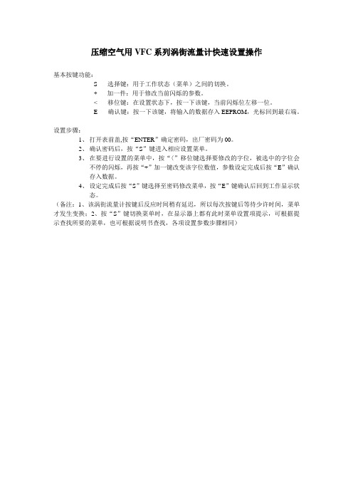
压缩空气用VFC系列涡街流量计快速设置操作
基本按键功能:
S-----选择键:用于工作状态(菜单)之间的切换。
+-----加一件:用于修改当前闪烁的参数。
<-----移位键:在设置状态下,按一下该键,当前闪烁位左移一位。
E-----确认键:按一下该键,将输入的数据存入EEPROM,光标回到最右端。
设置步骤:
1、打开表前盖,按“ENTER”确定密码,出厂密码为00。
2、确认密码后,按“S”键进入相应设置菜单。
3、在要进行设置的菜单中,按“〈”移位键选择要修改的字位,被选中的字位会
不停的闪烁,再按“+”加一键改变该字位数值,参数设定完成后按“E”确认
存入数据。
4、设定完成后按“S”键选择至密码修改菜单,按“E”键确认后回到工作显示状
态。
(备注:1、该涡街流量计按键后反应时间稍有延迟,所以每次按键后等待少许时间,菜单才发生变换;2、按“S”键切换菜单时,在显示器上都有此时菜单设置项提示,可根据提示查找所要的菜单,也可根据说明书查找,各项设置参数步骤相同)。

海力姆SLF系列空气流量测试仪操作手册空气流量计按键功能:1、电源按钮。
按此按钮可开启和关闭仪表。
按住5秒钟不放可显示仪表的固件版本。
2、激活流速模式。
参见“测量流速”。
3、打开或关闭背照灯4、激活流量模式。
参见“测量流量”。
5、计算保存值的平均值。
6、激活实时,最小值最大值平均值(Min Max Avg)功能。
参见“最小值最大值平均值”。
7、用于增加手动输入值,滚动浏览存储位置,以及导览“设置”菜单。
8、按住2秒钟可在读取读数前将显示归零9、用于减少手动输入值,滚动浏览存储位置,以及导览“设置”菜单。
10、按此进入“设置”菜单。
参见“设置菜单”。
11、用于访问仪表上以黄色标示的二级功能12、用于保存数据和接受对设置菜单及流量参数所作的更改13、保持当前读数14、激活压力模式。
参见“测量差压”15、电源,要启动或关闭仪表,请按O。
仪表由四节AA电池供电。
要更换电池,请参见“维护”。
16、温度仪表上会显示周围环境温度作为参考。
温度可以以°C或°F作为显示单位。
请参见“设置菜单”。
17、保存样本,仪表在它的三种主要模式下保存各种样本。
要保存样本,请执行下面的步骤:当获取样本时,按I保存样本。
仪表的三种模式分别最多可保存99个样本。
一旦获取了样本,按G可查看所有样本的平均值。
3.按G、P、V或F退出计算模式。
如果内存已满(已经保存了99个样本),则无法保存更多样本。
如果用户试图保存其它样本,仪表会闪动显示“Full”(已满),且不保存新的读数。
18、测量差压,要测量差压,请执行下面的步骤:按P 进入压力模式。
将单根软管连接到“Input (+)”端口,而保留“Ref (-)”端口不连接。
在管道向周围环境敞开时,按住Z键2秒钟。
将输入软管放置到一个不同于仪表所在位置的区域。

必需把握压的缩空气流量计使用注意事项流量计操作规程压缩空气是一种紧要的动力源,其具有震动大、气体带水、脉动流等特点,应用特别广。
无论是军事领域还是生活领域都可以找到压缩空气的身影。
因此认真了解把握压缩压缩空气是一种紧要的动力源,其具有震动大、气体带水、脉动流等特点,应用特别广。
无论是军事领域还是生活领域都可以找到压缩空气的身影。
因此认真了解把握压缩空气流量计使用注意事项是特别有必要的,也是必需的,从应用广度上来说,起码可以给使用单位节省不必要的经济损失。
(1)压缩空气流量计的测量范围较大,一般10:1,但测量下限受很多因素限制:Re>10000是智能涡街流量计工作的最基本条件,除此以外,它还受旋涡能量的限制,介质流速较低,则旋涡的强度、旋转速度也低,难以引起传感元件产生响应信号,旋涡频率f也小,还会使信号处理发生困难。
测量上限则受传感器的频率响应(如磁敏式一般不超过400Hz)和电路的频率限制,因此设计时确定要对流速范围进行计算、核算,依据流体的流速进行选择。
使用现场环境条件多而杂,选型时除注意环境温度、湿度、气氛等条件外,还要考虑电磁干扰。
(2)压缩空气流量计简单显现故障的一大劲敌是振动。
因此在使用时注意避开机械振动,尤其是管道的横向振动(垂直于管道轴线又垂直旋涡发生体轴线的振动),这种影响在流量计结构设计上是无法抑制和除去的。
由于涡街信号对流场影响同样敏感,故直管段长度不能保证稳定涡街所必要的流动条件时,是不宜选用的。
即使是抗振性较强的电容式、超声波式,保证流体为充分进展的单向流,也是不可疏忽的。
(3)压缩空气流量计能有效的检测压缩空气的流量,有传统意义的智能涡街流量计的特点又有改进后的抗振动、无堵塞的优点,针对介质有脉动流的特点,建议客户在压缩机出口设置一只缓冲罐滤除脉动,而将流量计安装在缓冲后面,或者将流量计安装在阔别脉动源的地方,这样可利用工艺管道的气容同其管阻构成低通滤波器衰减脉动。

希尔思中文操作手册S450复杂工况及防爆型热式质量流量计(插入式)尊敬的客户:感谢您选择我们的产品。
用户须在启动设备前完整阅读该操作手册并认真遵守。
对于因未仔细查看或者未遵守此操作手册规定而造成的任何损失,制造商概不负责。
如果用户违反此操作手册所描述或规定的方式,擅自改动设备,仪器保修将自动失效并且制造商免除责任。
请按照此操作手册说明的专业用途使用该设备。
对于该设备在未描述用途上的适用性,希尔思公司不做任何保证。
由于运输、设备性能或使用造成的间接损失,希尔思公司不承担责任。
2 SUTO · S450目录1 安全说明 (4)2 注册商标声明 (6)3 应用 (6)4 特点 (6)5 技术参数 (7)5.1 常规 (7)5.2 电气参数 (8)5.3 输出信号 (8)5.4 精度 (8)5.5 流量范围 (9)6 尺寸图 (10)7 确定安装点 (11)7.1 预留上下游段均衡区 (11)8 安装 (13)8.1 安装要求 (14)8.2 安装步骤 (14)8.2.1 确定流量计的插入深度 (15)8.2.2 安装流量计 (16)8.2.3 拆卸流量计 (17)8.3 电气连接 (17)8.3.1 连接图 (17)8.3.2 引脚分配 (18)9 信号输出 (19)9.1 模拟与脉冲输出 (19)9.1.1 模拟输出 (19)9.1.2 脉冲输出 (19)9.2 HART 输出 (20)9.3 Modbus接口 (20)9.4 M-Bus 输出 (22)9.5 S450信号输出与用户设备的连接 (22)10 显示屏 (25)10.1 启动信息 (25)10.2 测量数据及符号 (25)11 配置 (26)12 可选配件 (28)12.1 显示屏 (28)12.2 服务套装 (28)13 校准 (29)14 维护 (29)15 废弃物的处置 (29)SUTO · S45031 安全说明1 安全说明请检查此操作手册和产品类型是否匹配。
The Series CAM Compressed Air Meter operates by the calorimetricmeasuring principle to detect the standard volume flow of operatingcompressed air. It is designed specifically to evaluate the current flowrate and the current consumed quantity in compressed air systems. Withan easily programmable digital display, this unit offers a quick, accuratereadout. The Series CAM is constructed of high-grade materials and isvirtually maintenance free.Read the product description before installing the unit, to ensure that theproduct is suitable for your application without any restrictions. Suitablyqualified personnel must perform work on compressed air equipment.Ensure that the installation is at a standstill, before mounting compo-nents into or removing them from compressed air equipment. Ensurethat neither people nor objects are endangered by moving parts beforecommissioning / restart of the installation. Non-adherence to the operat-ing instructions or technical data can lead to personal injury and/or dam-age to property. In all applications, check compliance of the productmaterials with the media to be measured.SPECIFICATIONS Service: Compressed air; Air quality (see chart 1).Wetted Materials: Stainless Steel (304S15), ceramics, glass passivat-ed, PEEK, polyester, Fluoroelastomer, anodized aluminum.Response Time: < 0.1 seconds.Temperature Limit: 32 to 140°F (0 to 60°C).Accuracy*: 1.41 ±3% +0.3% FV; 3.44 ±6% MV +0.6% FV.Pressure Limit: 232 psig (16 bar).Humidity Limit: 90% RH.Power Requirements: 19-30 DC.Output Signal: Output 1: PNP Open Collector: VOUT(max)=30 VDC / ISINK(max)= 250mA Output 2: 4-20mA (scalable) or PNP Open Collector.Loop Resistance: 500 ohms.Current Consumption: <100 mA.Electrical Connections: 4 pin M12(Micro) Cable Connection.Process Connections: 1/2˝ , 1˝ and 2˝ NPT.Display:4-digit alphanumeric red LED Enclosure Rating: IP65 (NEMA 4X).Mounting Orientation: Vertical, Horizontal, Side with pipe length fac-ing left.Ranges: CAM-10: 1.4-412.0 SCFM;CAM-20: 0.2-44.1 SCFM;CAM-30: 1.0-132.4 SCFM.Weight:CAM-10: 12.5 lb;CAM-20: 2.35 lb;CAM-30: 4.16 lb.Agency Approvals: CE.*Ref. Chart 1 for DIN ISO 8573 Standards e.g. 1.4.1. implies 1 = 0.01mg/m 3oil content 4 = 15 µm particle size and 8 mg/m 3particle density1 = -70°C dew pt., 3 mg/m 3residual water Chart 1MODEL CAM-10CAM-20CAM-30A10-53/64[275.3]8-9/32[210.34]14-49/64[375.05]B 18-45/64[475.06]11-13/16[300.04]18-45/64[475.06]C 2 NPT 1/2 NPT 1 NPT D 5-1/4[133.35]3-1/32[76.99]3-31/64[88.5]E Ø2-1/64[Ø51.2]Ø41/64[Ø16.27]Ø1-5/64[Ø27.38]DIMENSIONSFigure 3Core socket colorsFigure 2Display Key Functions:Figure 4Chart 2*To decrease the value, cycle past the maximum value, and the setting will restartfrom the minimum.PROGRAMMINGSelect the display unit (Uni) before setting the values for the parameters. This avoids rounding errors generated internally during the conversion of the units and enables exact setting of the values. The setting at the fac-tory is Uni=CFH.If no button is pressed for 15 seconds during the setting procedure, the unit returns to the Run Mode with unchanged values.The unit can be electronically locked to prevent unwanted adjustment of the set parameters by pressing both push buttons until “LOC” is dis-played. With the unit in the locked state “LOC” is indicated briefly when you try to change parameter values. To unlock press both push buttons until “ULO” is displayed. Units are delivered from the factory in the unlocked state.OPERATING MODESRun Mode:Normal operating mode. Unit will perform its measurement and evalua-tion functions and provide output signals according to set parameters. Totalizer adds pulses of consumed quantity and displays them as cur-rent consumption value since last reset. Totalizer stores intermediate values every 10 minutes as well as elapsed time of set automatic reset. After a voltage dip this value is available as the current count of the total-izer (possible data loss can be maximum 10 minutes). Display indicates current measured values, yellow LED’s signal switching status of out-puts. Display unit can be temporarily changed (press “Set” button briefly, after 15 seconds unit returns to display unit set in menu point Uni). Display Mode:Indicates parameters and set parameter values. When “Mode/Enter”button is pushed briefly, unit passes to Display mode, which allows para-meter values to be read. Unit’s internal sensing, processing, and output functions continue as if in Run mode. Parameter names are scrolled with each press of “Mode/Enter” button. When “Set” button is pushed, corre-sponding parameter value is displayed for about 15 seconds. After another 15 seconds, unit returns to Run mode.Programming Mode:Setting parameter values: While viewing a parameter value pressing the “Set” button for more than 5 seconds causes unit to enter programming mode. Alter parameter by pressing “Set” button and confirm new value by pressing “Mode/Enter” button. Internal sensing, processing, and out-put functions continue as if in Run mode with original parameter values unless a new value is confirmed. Unit returns to Run mode when no but-ton has been pressed for 15 seconds.ADJUSTABLE PARAMETERS©Copyright 2009 Dwyer Instruments, Inc. Printed in U.S.A. 9/09 FR# RA-443445-00 Rev. 2Hysteresis Function:Keeps switching state of output stable if flow rate varies about presetvalue. With flow rate rising, output switches when switch-on point hasbeen reached (SPx). With flow rate falling, output does not switch backuntil switch-off point (rPx) has been reached. To adjust hysteresis: setswitch-on point, then set switch-off point at requested distance.Window Function:Enables monitoring of a defined acceptable range. When flow rate variesbetween switch-on point (SPx) and switch-off point (rPx), output isswitched (window function/NO) or not switched (window function/NC).Width of window can be set by means of the difference between SPx andrPx. SPx=upper value, rPx=lower value.Scaling measuring range (analog output):Analog start point (ASP) is the measured value at which the output sig-nal 4 mA is defined. Analog end point (AEP) is the measured value atwhich the output signal 20 mA is defined. Minimum distance betweenASP and AEP = 25% of final measuring range value. Output signalranges from 4 to 20 mA in set measuring range. Output is also indicatedby: flow rate above measuring range (output signal > 20 mA), or flow ratebelow measuring range (output signal between 3.6 and 4 mA).Fault IndicationOL: Detection range exceeded (flow rate > 120% of final value of mea-suring range)SC 1: Flashing - short circuit in switching output 1*SC 2: Flashing - short circuit in switching output 2*SC: Flashing - short circuit in both switching output*Err: Flashing - fault in measuring probe*Concerned output is switched off as long as short circuit continues.Faults are indicated even if display is deactivated.Figure 7Figure 5Figure 6Chart 3。
PV = nRT,where:P = pressure of the gasV = volume that the gas occupies n = number of molecules (i.e., mass)R = ideal gas constant T = temperature of the gas The ideal gas law defines the volume a certain mass of gas will occupy under specific conditions.For example, say a fixed mass of gas occupies a one liter container at 70°F under 1 atmosphere pressure.When the pressure of the system is increased (with the temperature held constant), the volume will decrease.If the temperature is increased, (with the volume held constant), the pressure will increase. The only constant variable is the mass of the gas; it does not change.Mass flow is the molecularmeasurement of the gas flowrate.This is usually measured in units of mass per unit of time, askilograms per hour. However, gas flow is usually measured in volume,such as liters per hour, but, since volume is dependent upon temperature and pressure, it isINTRODUCTIONThe continuing need for improved accuracy in flow measurement of mass related processes such as chemical reactions and thermal transfers has resulted in the development of electronic mass flowmeters. Thermal-type mass flowmeters operate with minor dependence on density, pressure,and fluid viscosity. This style of flowmeter utilises a heated sensing element and thermodynamic heat conduction principles to determine the true mass flow rate.Understanding Mass FlowTo understand the mass flow concept, it is essential to begin with the relationship between mass,temperature and pressure. Real gases roughly follow the ideal gas law, which states that the pressure,temperature and volume of a gas are all interrelated.ELECTRONIC MASS FLOWMETERSFlow Reference Sectiontherefore necessary to adoptstandard temperature and pressure conditions before one can define volumetric flow rate. Usually, these conditions are specified as 70°F and 1 atmosphere (14.7 psia) ing these standards, it is possible to take an exact mass flow andShown Smaller Than Actual SizeFMA-2100 Series (from £331)Figure 1: Insertion style mass flow sensor utilises RTD sensor to measure the flow rateD-3FMA-3300 series (from £267), see page D-14FMA-1700/FMA-1800series (from £289),see page D-15and 100 psig, flowing at 100 ACFM: Q s = 100 ACFM x(100 psig +14.7 psia)x(14.7 psia)(529.4 R)(459.4 + 100°F)OPERATING PRINCIPLE Electronic mass flowmeters and flow controllers employ thermodynamic principles to measure true mass flow rate without the need for temperature or pressure compensation. The following is a brief description of the two operating principles employed:heated tube and immersed probe.Heated TubeFMA-A2000, FMA-1700/1800,FMA-3300 Series FlowmetersIn these units, all or part of the gas flow passes through a precision-manufactured sensing tube (Fig. 2). Heat (Q) is applied to the gas flowing through the sensor tube via two externally wound resistance temperature detectors (T 1and T 2).The detectors have a dual function: toboth heat and sense the sensor-tubetemperature. When the molecules ofthe gas pass through the upstreamsensor winding (T 1) they carry away a certain amount of heat.reference it to more traditional measures without losing accuracy.For example, a 500 lb. per hour flow of nitrogen can be translated into standard cubic feet per minute (SCFM) units using the following relationship:•Q s = m/()s where:()s = density of the gasat standard conditions •m =mass flow rate Q s =standard mass flow rate(e.g., SCFM)In many applications, only the volumetric flow rate referenced to the actual pipe conditions is known.To convert actual cubic feet per minute (ACFM) to standardconditions (SCFM), the following relationship is used:Q s = Q a x (P a /P s ) x (T s /T a )where:P a = actual pressure P s = standard pressure T s = standard temperatureT a = actual temperature conditions Q a = actual mass flow rate(e.g., ACFM)For example, to determine thestandard flowrate of a gas at 100°FThis process is repeated at the downstream sensor winding (T 2)but less heat is transferred from the downstream sensor winding due to the flow’s having been preheated by the first sensor. The temperature differential (T 2-T 1)between the two sensors in aWheatstone bridge circuit ismeasured. Since the temperature difference between the two sensors is directly proportional to the mass flow of the gas (m), a highly accurate and repeatable flow measurement is obtained.Electronic mass flowmeters are not affected by pressure or temperature changes over the specified range ofthe unit.Also, heated tube mass flowmeters can accommodate virtually any clean gas. If the flow rangeremains the same, a correlation factor (K) is typically used torelate the calibration of nitrogen to the actual gas, This K factor is derived experimentally or from the gas density and coefficient of specific heat: K = ()C Pwhere:= gas density (g/liter) C P =coefficient of specific heat (cal/gram °C)D-4The flowrate of a reference gas (subscript “r”) and that of an actual gas (subscript “a”) are related as follows:Q a = (K r /K a )Q r=a a Where:Q = mass flow rate in SCCMNote that, in the above relationship,() and Cp are usually established under standard conditions.For example, to determine the flow rate of carbon dioxide (CO 2) when the flowmeter is calibrated in nitrogen at 100 SCCM, the conversion equation is Q CO 2=Q N 22CO 2=1.16 x 0.249x 100 = 77.0 SCCM 1.84 x 0.204A partial listing of correction factors for different gases is provided on page D-22. Consult Engineering for other factors.Flexibility, easy maintenance, and excellent low-flow sensitivity are the major benefits of heated tube mass flowmeters. The addition of an electromagnetically controlled automatic valve turns the meter into a mass flow controller, ideal for any application where mass (as opposed to volumetric) flowrate control is desired.The only requirement for this type flowmeter is that the fluid should be very clean (e.g., bottled gases),since the design makes these units very sensitive to dirt particles. For flows with any particulates present,the immersed probe style mass flowmeter should be considered.Immersion Probe StyleThese units consist of a thermal mass flow probe and integralelectronics for a linearised analog output (usually 0-5 Vdc, or 4-20 mA).The probe itself consists of two temperature-sensitive RTD(resistance temperature detector sensors). Both are constructed of reference grade platinum, coatedELECTRONIC MASS FLOWMETERSFlow Reference SectionFigure 3: Heated tube mass flow controllerxx D-5with glass. These sensors are large,rugged, insensitive to dirt, and easily cleaned. The first sensor constantly measures the ambient temperature of the gas flow and maintains the operational temperature differential of the second sensor. If the temperature of the flow varies, the first sensor detects and references it, providing a temperature-compensated basis for measurement.The second sensor is the flowdetection sensor, and is heated to a temperature 60°F higher than the first. As the gas flows past, a certain amount of heat is transferred from the heated sensor to the gas. The heat transfer rate is proportional to the mass velocity of the gas, or ()V. It is this principle of heattransfer from the sensor to the gas that is the key to the immersion-style probe. When the flow of gas passing over the flow sensorincreases, the sensor loses more heat to the gas. As it loses heat,more current is needed to maintain the 60°F temperature differentialbetween the two sensors. The twosensors operate together as part of a Wheatstone forced null bridge circuit (Fig. 4). The output signal of the sensor is the bridge voltage (or current) required to maintain the constant temperature differential,which is non-linearly proportional to the mass velocity ()V. The non-linear output of the bridge circuit is then linearised and converted to a standard analogue output signal by the integrally mounted electronics.Special Consideration for Insertion ProbesOMEGA ®FMA Series air velocity transducers measure air mass velocity. Mass velocity is velocity weighed by the gas density ()V.The fundamental units of (V) are Ib-m/ft 3x ft/min, or lb-m/ft 2/min, but,normally,(V) is referred to in terms of standard feet per minute (SFPM),where the standard reference conditions are 25°C and1 atmosphere pressure. To convert from SFPM to standard cubic feet per minute (SCFM), multiply the standard velocity in SFPM by the cross sectional pipe area. (For pipecross sectional area, see page Z-27). To convert from SCFM to actual cubic feet per minute, refer to the equation for converting from actual to standardised flowrate. FMA Series air velocity transducers measure the air mass velocity at the location of the flow sensor. Thepoint of measurement can be critical if flows are not uniform or flat. If a duct does not have a uniform flow,point measurements will not be the same throughout (see Fig. 5). Flow in a straight duct or pipe will usually be symmetrical and relatively uniform if the ratio of straight pipe length to pipe diameter is at least 10to 1 and the duct walls are relatively smooth. For example, 10 diameters in a 6" diameter pipe is 60". Tees,elbows, valves and other flowobstructions will cause irregularities in the flow until they have asufficient length of straight pipe to become more uniform. If a straight section of duct greater than 10diameters in length is unavailable,other approaches may be employed as outlined in the instruction manual provided with the unit.Model FMA-78C108 ft. interconnecting cable sold separately (page D-8)Model FMA-78P4 Readout/Power Supply Electronics (page D-8)Model FMA-760D-6D。
智能气体涡轮流量计使用说明书目录一、概述 (1)二、主要特征 (1)三、技术性能 (1)四、选型与安装 (3)五、安装注意事项 (7)注意!●安装使用前,请仔细阅读本说明书理解各项内容,以便能正确的安装、电路连接、运行操作和保养维护等。
●本说明书应保存在实际最终使用人的手中。
●本说明书保存到流量计报废为止。
●本产品技术规范可能发生变化,恕不另行通知。
一、概述LWQ型气体涡轮流量计是一种精确测量气体流量的速度式流量仪表,具有结构简单轻巧、计量精度高、重复性好、测量范围宽、安装维修方便等优点。
广泛应用于石油、化工、冶金、航空、科研等部门及工业领域中多种气体,如天然气、城市煤气、丙烷、丁烷、空气、氮气等气体的测量。
由于仪表精度高、重复性好,故适用于贸易计量及工业过程检测。
气体涡轮流量计在线测量时,其介质密度随温度和压力变化而变化,为精确测量,必须同时跟踪检测介质的温度和压力,并将不同工况下的体积流量换算成标准状态或约定状态下的体积流量。
由于该型流量计集温度、压力、流量传感器于一体,在线跟踪检测介质温度和压力并进行自动补偿、压缩因子修正运算,因此具有优良的低压和高压计量性能,特别适用于各种单相气体的测量,如天然气等气体的精确计量。
根据用户的不同要求,共公司客提供不同精度等级的涡轮流量计。
二、主要特征a)精度高、重复性好、压力损失小、抗震性能好;b)采用优质轴承,摩擦阻力小,密封性好,手名称;c)集微处理器、流量传感器、高精度温度、压力传感器于一体,直接测量被测气体的流量、温度、压力,并自动进行流量跟踪补偿和压缩因子修正运算;d)仪表具有脉冲信号、模拟信号输出,可通过RS485通讯接口或采用GPRS系统,直接实现计算机数据的集中采集和实时管理;e)功耗低,可用内电池供电,也可外接电源;f)具有实时数据存储功能,可防止更换电池或突然掉电时数据丢失,在停电状态下,内部数据可永久保存;g)可与IC卡预付费系统配套使用,便于贸易结算;h)防爆产品其防爆标志位ExibIIBT4,ExibIIBT6三、技术性能3.1执行标准GB/T18940-2003《封闭管道中气体流量的测量涡轮流量计》3.2精度等级1.0级:Qmax-0.2max±1.0%0.2Qmax-min±2.0%1.5级:Qmax-0.2max±1.5%0.2Qmax-min±3.0%未特殊注明产品,按照1.5级精度出厂,其余精度,订货时,需要特殊说明定制。
FLEXIM GmbHBoxberger Str. 412681 BerlinGermany电话: +49 (30) 93 66 76 60传真: +49 (30) 93 66 76 80保留不经事先通知变更的权利。
保留出错的权利。
FLUXUS 是 FLEXIM GmbH 的注册商标。
网址: 电子邮件:***************Copyright (©) FLEXIM GmbH 2023利用超声波对压缩空气进行非侵入式体积流量测量TSFLUXUS_G532CAV1-0-1ZH_Leu, 2023-06-12FLUXUS G532CA 技术规格2023-06-12, TSFLUXUS_G532CAV1-0-1ZH_Leu2功能. . . . . . . . . . . . . . . . . . . . . . . . . . . . . . . . . . . . . . . . . . . . . . . . . . .3测量原理. . . . . . . . . . . . . . . . . . . . . . . . . . . . . . . . . . . . . . . . . . . . . . . . .3计算体积流量. . . . . . . . . . . . . . . . . . . . . . . . . . . . . . . . . . . . . . . . . . . . . . .3计算标准体积流量. . . . . . . . . . . . . . . . . . . . . . . . . . . . . . . . . . . . . . . . . . . . .4声程数. . . . . . . . . . . . . . . . . . . . . . . . . . . . . . . . . . . . . . . . . . . . . . . . . .4典型测量布局. . . . . . . . . . . . . . . . . . . . . . . . . . . . . . . . . . . . . . . . . . . . . . .5测量变送器. . . . . . . . . . . . . . . . . . . . . . . . . . . . . . . . . . . . . . . . . . . . . . . .6技术参数. . . . . . . . . . . . . . . . . . . . . . . . . . . . . . . . . . . . . . . . . . . . . . . . .6尺寸. . . . . . . . . . . . . . . . . . . . . . . . . . . . . . . . . . . . . . . . . . . . . . . . . . .72"管道安装组件 (可选). . . . . . . . . . . . . . . . . . . . . . . . . . . . . . . . . . . . . . . . . .8存储. . . . . . . . . . . . . . . . . . . . . . . . . . . . . . . . . . . . . . . . . . . . . . . . . . .8端子分配. . . . . . . . . . . . . . . . . . . . . . . . . . . . . . . . . . . . . . . . . . . . . . . . .9传感器. . . . . . . . . . . . . . . . . . . . . . . . . . . . . . . . . . . . . . . . . . . . . . . . . 10技术参数. . . . . . . . . . . . . . . . . . . . . . . . . . . . . . . . . . . . . . . . . . . . . . . . 10传感器固定件. . . . . . . . . . . . . . . . . . . . . . . . . . . . . . . . . . . . . . . . . . . . . . 12传感器的耦合材料. . . . . . . . . . . . . . . . . . . . . . . . . . . . . . . . . . . . . . . . . . . . 12阻尼垫. . . . . . . . . . . . . . . . . . . . . . . . . . . . . . . . . . . . . . . . . . . . . . . . . 13连接系统. . . . . . . . . . . . . . . . . . . . . . . . . . . . . . . . . . . . . . . . . . . . . . . . 14接线盒. . . . . . . . . . . . . . . . . . . . . . . . . . . . . . . . . . . . . . . . . . . . . . . . . 15技术参数. . . . . . . . . . . . . . . . . . . . . . . . . . . . . . . . . . . . . . . . . . . . . . . . 15尺寸. . . . . . . . . . . . . . . . . . . . . . . . . . . . . . . . . . . . . . . . . . . . . . . . . . 152"管道安装组件. . . . . . . . . . . . . . . . . . . . . . . . . . . . . . . . . . . . . . . . . . . . . 16温度传感器. . . . . . . . . . . . . . . . . . . . . . . . . . . . . . . . . . . . . . . . . . . . . . . 17技术参数. . . . . . . . . . . . . . . . . . . . . . . . . . . . . . . . . . . . . . . . . . . . . . . . 17固定. . . . . . . . . . . . . . . . . . . . . . . . . . . . . . . . . . . . . . . . . . . . . . . . . . 17接线盒. . . . . . . . . . . . . . . . . . . . . . . . . . . . . . . . . . . . . . . . . . . . . . . . .18压力变送器 (可选). . . . . . . . . . . . . . . . . . . . . . . . . . . . . . . . . . . . . . . . . . . 20技术参数. . . . . . . . . . . . . . . . . . . . . . . . . . . . . . . . . . . . . . . . . . . . . . . . 20技术规格 FLUXUS G532CA3TSFLUXUS_G532CAV1-0-1ZH_Leu, 2023-06-12功能测量原理超声波传感器安装在管道上,该管道完全充满流体。