美标 ASTM A53
- 格式:doc
- 大小:109.50 KB
- 文档页数:2

astma53无缝钢管
产品类别:astm美标无缝钢管产品名称:astma53无缝钢管
astma53美国标准(无镀层及热浸镀锌焊接与无缝公称钢管
home--北钢管业
无缝钢管按其标准可分为astm美标无缝钢管din德标无缝钢管jis日标无缝钢管gb
国无缝钢管api无缝钢管等种类,astm美标无缝钢管在国际上较为通用,其种类分支繁多。
现将astm无缝钢管astma53美标无缝钢管相关参数陈列如下标准:
astma53/a53m/asmesa-53/sa-53m用途:
适用于作受力及承压件,也可以用于一般用途的蒸汽、水、气体及空气管线。
主要生产钢管牌号:a、b等
经协商,也可供应其它牌号的钢管。
机械性能:
remarks附注:
垂直挤压无缝钢管,前两种工艺是生产一般口径无缝钢管,无缝钢管的口径一般在8
-406,壁厚一般在2-25;后两种是生产大口径厚壁无缝钢管,无缝钢管口径一般在406
-1800,壁厚在20mm-220mm。
按其用途可分为结构用无缝钢管流体用无缝钢管锅炉用无
缝钢管石油管线用无缝钢管。
美标紧固件热浸锌标准
美标紧固件热浸锌标准通常按照ASTM A53进行。
ASTM A53是美标无缝钢管的标准,其中规定了热浸锌的要求。
热浸锌是一种金属表面处理方法,用于提高紧固件的防腐蚀能力。
在热浸锌过程中,将紧固件放入高温的锌液中浸泡一定时间,使其表面形成一层锌层,起到保护和装饰的作用。
根据ASTM A53标准,美标紧固件热浸锌的厚度要求通常与紧固件的规格和材质有关。
一般来说,紧固件的热浸锌厚度应不小于0.135盎司/平方英尺(约38克/平方米),但具体的厚度要求需要根据紧固件的具体规格和要求进行确定。
此外,ASTM A53标准还规定了其他方面的要求,如锌层的均匀性、附着性、耐腐蚀性等,以确保热浸锌处理的质量和效果。
需要注意的是,不同的紧固件材质和规格可能对热浸锌的要求有所不同,因此在选择热浸锌处理时,需要结合具体情况进行选择和处理。
Designation:A53/A53M–07Standard Specification forPipe,Steel,Black and Hot-Dipped,Zinc-Coated,Welded and Seamless1This standard is issued under thefixed designation A53/A53M;the number immediately following the designation indicates the year of original adoption or,in the case of revision,the year of last revision.A number in parentheses indicates the year of last reapproval.A superscript epsilon(e)indicates an editorial change since the last revision or reapproval.This standard has been approved for use by agencies of the Department of Defense.1.Scope*1.1This specification2covers seamless and welded black and hot-dipped galvanized steel pipe in NPS1⁄8to NPS26[DN 6to DN650](Note1),inclusive,with nominal wall thickness (Note2)as given in Table X2.2and Table X2.3.It shall be permissible to furnish pipe having other dimensions provided that such pipe complies with all other requirements of this specification.Supplementary requirements of an optional na-ture are provided and shall apply only when specified by the purchaser.N OTE1—The dimensionless designators NPS(nominal pipe size)[DN (diameter nominal)]have been substituted in this specification for such traditional terms as“nominal diameter,”“size,”and“nominal size.”N OTE2—The term nominal wall thickness has been assigned for the purpose of convenient designation,existing in name only,and is used to distinguish it from the actual wall thickness,which may vary over or under the nominal wall thickness.1.2This specification covers the following types and grades:1.2.1Type F—Furnace-butt-welded,continuous welded Grade A,1.2.2Type E—Electric-resistance-welded,Grades A and B, and1.2.3Type S—Seamless,Grades A and B.N OTE3—See Appendix X1for definitions of types of pipe.1.3Pipe ordered under this specification is intended for mechanical and pressure applications and is also acceptable for ordinary uses in steam,water,gas,and air lines.It is suitable for welding,and suitable for forming operations involving coiling,bending,andflanging,subject to the following quali-fications:1.3.1Type F is not intended forflanging.1.3.2If Type S or Type E is required for close coiling or cold bending,Grade A is the preferred grade;however,this is not intended to prohibit the cold bending of Grade B pipe. 1.3.3Type E is furnished either nonexpanded or cold expanded at the option of the manufacturer.1.4The values stated in either SI units or inch-pound units are to be regarded separately as standard.The values stated in each system may not be exact equivalents;therefore,each system is to be used independently of the other.1.5The following precautionary caveat pertains only to the test method portion,Sections7,8,9,13,14,and15of this specification:This standard does not purport to address all of the safety concerns,if any,associated with its use.It is the responsibility of the user of this standard to establish appro-priate safety and health practices and determine the applica-bility of regulatory requirements prior to use.1.6The text of this specification contains notes or footnotes, or both,that provide explanatory material.Such notes and footnotes,excluding those in tables andfigures,do not contain any mandatory requirements.2.Referenced Documents2.1ASTM Standards:3A90/A90M Test Method for Weight[Mass]of Coating on Iron and Steel Articles with Zinc or Zinc-Alloy Coatings A370Test Methods and Definitions for Mechanical Testing of Steel ProductsA530/A530M Specification for General Requirements for Specialized Carbon and Alloy Steel PipeA700Practices for Packaging,Marking,and Loading Methods for Steel Products for ShipmentA751Test Methods,Practices,and Terminology for Chemical Analysis of Steel ProductsA865Specification for Threaded Couplings,Steel,Black or Zinc-Coated(Galvanized)Welded or Seamless,for Use in Steel Pipe Joints1This specification is under the jurisdiction of ASTM Committee A01on Steel, Stainless Steel and Related Alloys and is the direct responsibility of Subcommittee A01.09on Carbon Steel Tubular Products.Current edition approved Sept.1,2007.Published October2007.Originally approved st previous edition approved in2006as A53/A53M–06a.2For ASME Boiler and Pressure Vessel Code applications,see related Specifi-cation SA-53in Section II of that code.3For referenced ASTM standards,visit the ASTM website,,or contact ASTM Customer Service at service@.For Annual Book of ASTM Standards volume information,refer to the standard’s Document Summary page on the ASTM website.*A Summary of Changes section appears at the end of this standard. Copyright©ASTM International,100Barr Harbor Drive,PO Box C700,West Conshohocken,PA19428-2959,United States.B 6Specification for ZincE 29Practice for Using Significant Digits in Test Data to Determine Conformance with SpecificationsE 213Practice for Ultrasonic Examination of Metal Pipe and TubingE 273Practice for Ultrasonic Examination of the Weld Zone of Welded Pipe and TubingE 309Practice for Eddy-Current Examination of Steel Tu-bular Products Using Magnetic SaturationE 570Practice for Flux Leakage Examination of Ferromag-netic Steel Tubular ProductsE 1806Practice for Sampling Steel and Iron for Determi-nation of Chemical Composition 2.2ANSI Standards:ASC X124B1.20.1Pipe Threads,General Purpose 42.3ASME Standard:B36.10M Welded and Seamless Wrought Steel Pipe 52.4Military Standards:MIL-STD-129Marking for Shipment and Storage 6MIL-STD-163Steel Mill Products Preparation for Ship-ment and Storage 62.5Federal Standards:Fed.Std.No.123Marking for Shipment (Civil Agencies)7Fed.Std.No 183Continuous Identification Marking of Iron and Steel Products 72.6API Standard:5B Specification for Threading,Gauging,and Thread In-spection of Casing,Tubing,and Line Pipe Threads 83.Ordering Information3.1Information items to be considered,if appropriate,for inclusion in the purchase order are as follows:3.1.1Specification designation (A 53or A 53M,including year-date),3.1.2Quantity (feet,metres,or number of lengths),3.1.3Grade (A or B),3.1.4Type (F,E,or S;see 1.2),3.1.5Finish (black or galvanized),3.1.6Size (either nominal (NPS)[DN]and weight class or schedule number,or both;or outside diameter and wall thickness,see Table X2.2and Table X2.3),3.1.7Length (specific or random,see Section 16),3.1.8End finish (plain end or threaded,Section 11),3.1.8.1Threaded and coupled,if desired,3.1.8.2Threads only (no couplings),if desired,3.1.8.3Plain end,if desired,3.1.8.4Couplings power tight,if desired,3.1.8.5Taper-tapped couplings for NPS 2[DN 50]and smaller,if desired,3.1.9Close coiling,if desired (see 7.2.2),3.1.10Nondestructive electric test for seamless pipe (see 9.2),3.1.11Certification (see Section 20),3.1.12Report of the length of the end effect,if desired (see 9.2.7),3.1.13Marking (see Section 21),3.1.14End use of pipe,3.1.15Special requirements,3.1.16Supplementary requirements,if any,3.1.17Selection of applicable level of preservation and packaging and level of packing required,if other than as specified or if MIL-STD-163applies (see 22.1),and3.1.18Packaging and package marking,if desired (see 23.1).4.Materials and Manufacture4.1The steel for both seamless and welded pipe shall be made by one or more of the following processes:open-hearth,electric-furnace,or basic-oxygen.4.2If steels of different grades are sequentially strand cast,identification of the resultant transition material is required.The steel producer shall remove the transition material by any established procedure that positively separates the grades.4.3The weld seam of electric-resistance welded pipe in Grade B shall be heat treated after welding to a minimum of 1000°F [540°C]so that no untempered martensite remains,or otherwise processed in such a manner that no untempered martensite remains.4.4When pipe is cold expanded,the amount of expansion shall not exceed 11⁄2%of the specified outside diameter of the pipe.5.Chemical Composition5.1The steel shall conform to the requirements as to chemical composition given in Table 1and the chemical4Available from American National Standards Institute (ANSI),25W.43rd St.,4th Floor,New York,NY 10036,.5Available from American Society of Mechanical Engineers (ASME),ASME International Headquarters,Three Park Ave.,New York,NY 10016-5990,.6Available from Standardization Documents Order Desk,DODSSP,Bldg.4,Section D,700Robbins Ave.,Philadelphia,PA 19111-50987Available from General Services Administration,Washington,DC 20405.8Available from American Petroleum Institute (API),1220L.St.,NW,Wash-ington,DC 20005-4070,.TABLE 1Chemical RequirementsComposition,max,%CarbonManganesePhosphorus Sulfur Copper A Nickel AChromium AMolybdenum AVanadium AType S (seamless pipe)Grade A 0.250.950.050.0450.400.400.400.150.08Grade B 0.30 1.200.050.0450.400.400.400.150.08Type E (electric-resistance-welded)Grade A 0.250.950.050.0450.500.400.400.150.08Grade B 0.30 1.200.050.0450.500.400.400.150.08Type F (furnace-welded pipe)Grade A0.301.200.050.0450.400.400.400.150.08AThe total composition for these five elements shall not exceed 1.00%.analysis shall be in accordance with Test Methods,Practices,and Terminology A 751.6.Product Analysis6.1The purchaser is permitted to perform an analysis of two pipes from each lot of 500lengths,or fraction thereof.Samples for chemical analysis,except for spectrographic analysis,shall be taken in accordance with Practice E 1806.The chemical composition thus determined shall conform to the requirements given in Table 1.6.2If the analysis of either pipe does not conform to the requirements given in Table 1,analyses shall be made on additional pipes of double the original number from the same lot,each of which shall conform to the specified requirements.7.Mechanical Properties 7.1Tension Test :7.1.1For tension tests other than transverse weld tension tests,the yield strength corresponding to a permanent offset of 0.2%of the gage length or to an extension of 0.5%of the gage length under load,the tensile strength,and the elongation in 2in.or 50mm shall be determined,and the tension test results shall conform to the applicable tensile property requirements given in Table 2.7.1.2For transverse weld tension tests,the tensile strength shall be determined,and the tension test results shall conform to the applicable tensile strength requirement given in Table 2.7.1.3Electric-resistance-welded pipe NPS 8[DN 200]or larger shall be tested using two transverse test specimens,one taken across the weld and one taken opposite the weld.7.1.4Transverse tension test specimens shall be approxi-mately 11⁄2in.[38mm]wide in the gage length and shall represent the full wall thickness of the pipe from which the test specimens were cut.7.2Bend Test :7.2.1For pipe NPS 2[DN 50]or smaller,a sufficient length of pipe shall be capable of being bent cold through 90°around a cylindrical mandrel,the diameter of which is twelve times the specified outside diameter of the pipe,without developing cracks at any portion and without opening the weld.7.2.2If ordered for close coiling,the pipe shall stand being bent cold through 180°around a cylindrical mandrel,the diameter of which is eight times the specified outside diameter of the pipe,without failure.7.2.3Double-extra-strong pipe over NPS 11⁄4[DN 32]need not be subjected to the bend test.7.3Flattening Test :7.3.1The flattening test shall be made on welded pipe over NPS 2[DN 50]in extra-strong weight or lighter.7.3.2Seamless Pipe :7.3.2.1Although testing is not required,pipe shall be capable of meeting the flattening test requirements of Supple-mentary Requirement S1,if tested.7.3.3Electric-Resistance-Welded Pipe :7.3.3.1A test specimen at least 4in.[100mm]in length shall be flattened cold between parallel plates in three steps,with the weld located either 0°or 90°from the line of direction of force as required by 7.3.3.2or 7.3.3.3,whichever is applicable.During the first step,which is a test for ductility of the weld,except as allowed by 7.3.5,7.3.6,and 7.3.7,no cracks or breaks on the inside or outside surface at the weld shall be present before the distance between the plates is less than two thirds of the specified outside diameter of the pipe.As a second step,the flattening shall be continued as a test for ductility away from the weld.During the second step,except as allowed by 7.3.6and 7.3.7,no cracks or breaks on the inside or outside surface away from the weld shall be present before the distance between the plates is less than one third of the specified outside diameter of the pipe but is not less than five times the specified wall thickness of the pipe.During the third step,which is a test for soundness,the flattening shall be continued until the test specimen breaks or the opposite walls of the test specimen meet.Evidence of laminated or unsound material or of incom-plete weld that is revealed by the flattening test shall be cause for rejection.7.3.3.2For pipe produced in single lengths,the flattening test specified in 7.3.3.1shall be made using a test specimen taken from each end of each length of pipe.The tests from each end shall be made alternately with the weld at 0°and at 90°from the line of direction of force.7.3.3.3For pipe produced in multiple lengths,the flattening test specified in 7.3.3.1shall be made as follows:(1)Test specimens taken from,and representative of,the front end of the first pipe intended to be supplied from each coil,the back end of the last pipe intended to be supplied from each coil,and each side of any intermediate weld stop location shall be flattened with the weld located at 90°from the line of direction of force.(2)Test specimens taken from pipe at any two locations intermediate to the front end of the first pipe and the back end of the last pipe intended to be supplied from each coil shall be flattened with the weld located at 0°from the line of direction of force.7.3.3.4For pipe that is to be subsequently reheated through-out its cross section and hot formed by a reducing process,the manufacturer shall have the option of obtaining the flattening test specimens required by 7.3.3.2or 7.3.3.3,whichever is applicable,either prior to or after such hot reducing.TABLE 2Tensile RequirementsGrade AGrade B Tensile strength,min,psi [MPa]48000[330]60000[415]Yield strength,min,psi [MPa]30000[205]35000[240]Elongation in 2in.or 50mmA ,BA ,BAThe minimum elongation in 2in.[50mm]shall be that determined by the following equation:e 5625000[1940]A 0.2/U 0.9where:e =minimum elongation in 2in.or 50mm in percent,rounded to the nearestpercent,A =the lesser of 0.75in.2[500mm 2]and the cross-sectional area of thetension test specimen,calculated using the specified outside diameter of the pipe,or the nominal width of the tension test specimen and the specified wall thickness of the pipe,with the calculated value rounded to the nearest 0.01in.2[1mm 2],andU =specified minimum tensile strength,psi [MPa].BSee Table X4.1or Table X4.2,whichever is applicable,for the minimum elongation values that are required for various combinations of tension test specimen size and specified minimum tensilestrength.7.3.4Continuous-Welded Pipe—A test specimen at least4 in.[100mm]in length shall beflattened cold between parallel plates in three steps.The weld shall be located at90°from the line of direction of force.During thefirst step,which is a test for ductility of the weld,except as allowed by7.3.5,7.3.6,and 7.3.7,no cracks or breaks on the inside,outside,or end surfaces at the weld shall be present before the distance between the plates is less than three fourths of the specified outside diameter of the pipe.As a second step,theflattening shall be continued as a test for ductility away from the weld. During the second step,except as allowed by7.3.6and7.3.7, no cracks or breaks on the inside,outside,or end surfaces away from the weld shall be present before the distance between the plates is less than60%of the specified outside diameter of the pipe.During the third step,which is a test for soundness,the flattening shall be continued until the test specimen breaks or the opposite walls of the test specimen meet.Evidence of laminated or unsound material or of incomplete weld that is revealed by theflattening test shall be cause for rejection. 7.3.5Surface imperfections in the test specimen before flattening,but revealed during thefirst step of theflattening test,shall be judged in accordance with thefinish requirements in Section12.7.3.6Superficial ruptures as a result of surface imperfec-tions shall not be cause for rejection.7.3.7For pipe with a D-to-t ratio less than10,because the strain imposed due to geometry is unreasonably high on the inside surface at the6and12o’clock locations,cracks at such locations shall not be cause for rejection.8.Hydrostatic Test8.1The hydrostatic test shall be applied,without leakage through the weld seam or the pipe body.8.2Plain-end pipe shall be hydrostatically tested to the applicable pressure given in Table X2.2,and threaded-and-coupled pipe shall be hydrostatically tested to the applicable pressure given in Table X2.3.It shall be permissible,at the discretion of the manufacturer,to perform the hydrostatic test on pipe with plain ends,with threads only,or with threads and couplings;and it shall also be permissible to test pipe in either single lengths or multiple lengths.N OTE4—The hydrostatic test pressures given herein are inspection test pressures,are not intended as a basis for design,and do not have any direct relationship to working pressures.8.3The minimum hydrostatic test pressure required to satisfy the requirements specified in8.2need not exceed2500 psi[17200kPa]for pipe NPS3[DN80]or smaller,or2800 psi[19300kPa]for pipe larger than NPS3[DN80];however, the manufacturer has the option of using higher test pressures. For all sizes of seamless pipe and electric-resistance-welded pipe,the hydrostatic test pressure shall be maintained for at least5s.9.Nondestructive Electric Test9.1Type E Pipe:9.1.1Except for pipe produced on a hot-stretch reducing mill,the weld seam of each length of electric-resistance-welded pipe NPS2[DN50]or larger shall be tested with a nondestructive electric test in accordance with Practices E213, E273,E309,or E570.Each length of electric-resistance-welded pipe NPS2[DN50]or larger and produced on a hot-stretch-reducing mill shall be tested with a nondestructive electric test that inpsects the full volume of the pipe in accordance with Practices E213,E309,or E570.9.1.2Ultrasonic and Electromagnetic Inspection—Any equipment utilizing the ultrasonic or electromagnetic principles and capable of continuous and uninterrupted inspection of the weld seam shall be used.The equipment shall be checked with an applicable reference standard as described in9.1.3at least once every working turn or not more than8h to demonstrate its effectiveness and the inspection procedures.The equipment shall be adjusted to produce well-defined indications when the reference standard is scanned by the inspection unit in a manner simulating the inspection of the product.9.1.3Reference Standards—The length of the reference standards shall be determined by the pipe manufacturer,and they shall have the same specified diameter and thickness as the product being inspected.Reference standards shall contain machined notches,one on the inside surface and one on the outside surface,or a drilled hole,as shown in Fig.1,at the option of the pipe manufacturer.The notches shall be parallel to the weld seam,and shall be separated by a distance sufficient to produce two separate and distinguishable signals.The1⁄8-in.[3.2-mm]hole shall be drilled through the wall and perpen-dicular to the surface of the reference standard as shown in Fig.1.Care shall be taken in the preparation of the reference standard to ensure freedom fromfins or other edge roughness, or distortion of the pipe.N OTE5—The calibration standards shown in Fig.1are convenient standards for calibration of nondestructive testing equipment.The dimen-sions of such standards are not to be construed as the minimum sizes of imperfections detectable by such equipment.9.1.4Acceptance Limits—Table3gives the height of accep-tance limit signals in percent of the height of signals produced by reference standards.Imperfections in the weld seam that produce a signal greater than the acceptance limit signal given in Table3shall be considered a defect unless the pipe manufacturer can demonstrate that the imperfection does not reduce the effective wall thickness beyond12.5%of the specified wall thickness.9.2Type S Pipe—As an alternative to the hydrostatic test at the option of the manufacturer or if specified in the purchase order,the full body of each seamless pipe shall be tested with a nondestructive electric test in accordance with Practice E213,E309,or E570.In such cases,each length so furnished shall include the mandatory marking of the letters“NDE.”Except as allowed by9.2.6.2,it is the intent of this nondestruc-tive electric test to reject pipe with imperfections that produce test signals equal to or greater than those produced by the applicable calibration standards.9.2.1If the nondestructive electric test has been performed, the lengths shall be marked with the letters“NDE.”The certification,if required,shall state Nondestructive Electric Tested and shall indicate which of the tests was applied.Also, the letters NDE shall be appended to the product specification number and grade shown on thecertification.9.2.2The following information is intended to facilitate the use of this specification:9.2.2.1The calibration standards defined in 9.2.3through 9.2.5are convenient standards for calibration of nondestructive testing equipment.The dimensions of such standards are not to be construed as the minimum sizes of imperfections detectable by such equipment.9.2.2.2The ultrasonic testing referred to in this specification is capable of detecting the presence and location of significant longitudinally or circumferentially oriented imperfections;however,different techniques need to be employed for the detection of differently oriented imperfections.Ultrasonic test-ing is not necessarily capable of detecting short,deep imper-fections.9.2.2.3The eddy current examination referenced in this specification has the capability of detecting significant discon-tinuities,especially of the short abrupt type.9.2.2.4The flux leakage examination referred to in this specification is capable of detecting the presence and location of significant longitudinally or transversely oriented disconti-nuities.The provisions of this specification only require longitudinal calibration for flux leakage.Different techniques need to be employed for the detection of differently oriented imperfections.9.2.2.5The hydrostatic test referred to in 8.2has the capability of finding imperfections of a size permitting the test fluid to leak through the tube wall and may be either visually seen or detected by a loss of pressure.Hydrostatic testing is notnecessarily capable of detecting very tight through-the-wall imperfections or imperfections that extend an appreciable distance into the wall without complete penetration.9.2.2.6A purchaser interested in ascertaining the nature (type,size,location,and orientation)of imperfections that are capable of being detected in the specific application of these examinations is directed to discuss this with the manufacturer of the tubular product.9.2.3For ultrasonic testing,the calibration reference notches shall be at the option of the manufacturer,and shall be any one of the three common notch shapes shown in Practice E 213.The depth of notch shall not exceed 12.5%of the specified wall thickness of the pipe or 0.004in.[0.1mm],whichever is the greater.9.2.4For eddy current testing,the calibration pipe shall contain,at the option of the manufacturer,any one of the following calibration standards to establish a minimum sensi-tivity level for rejection.9.2.4.1Drilled Hole —The calibration pipe shall contain three holes spaced 120°apart or four holes spaced 90°apart,sufficiently separated longitudinally to ensure separately dis-tinguishable responses.The holes shall be drilled radially and completely through the pipe wall,care being taken to avoid distortion of the pipe while drilling.Dependent upon the nominal pipe size,the calibration pipe shall contain the following hole:NPS DN Diameter of Drilled Hole #1⁄2#150.039in.[1.0mm]>1⁄2#11⁄4>15#320.055in.[1.4mm]>11⁄4#2>32#500.071in.[1.8mm]>2#5>50#1250.087in.[2.2mm]>5>1250.106in.[2.7mm]9.2.4.2Transverse Tangential Notch —Using a round tool or file with a 1⁄4in.[6mm]diameter,a notch shall be filed or milled tangential to the surface and transverse to the longitu-dinal axis of the pipe.The notch shall have a depthnotFIG.1Calibration StandardsTABLE 3Acceptance LimitsType NotchSize of HoleAcceptanceLimit Signal,%in.mm N10,V10B,P1⁄8...3.2...10080exceeding12.5%of the specified wall thickness of the pipe or 0.012in.[0.3mm],whichever is the greater.9.2.4.3Longitudinal Notch—A notch0.031in.[0.8mm]or less in width shall be machined in a radial plane parallel to the pipe axis on the outside surface of the pipe,to a depth not exceeding12.5%of the specified wall thickness of the pipe or 0.012in.[0.3mm],whichever is the greater.The length of the notch shall be compatible with the testing method.9.2.4.4Compatibility—The calibration standards in the cali-bration pipe shall be compatible with the testing equipment and the method being used.9.2.5Forflux leakage testing,the longitudinal calibration reference notches shall be straight-sided notches machined in a radial plane parallel to the pipe axis.For specified wall thicknesses less than0.500in.[12.7mm],outside and inside notches shall be used.For specified wall thicknesses equal to or greater than0.500in.[12.7mm],only an outside notch shall be used.The notch depth shall not exceed12.5%of the specified wall thickness,or0.012in.[0.3mm],whichever is the greater. The notch length shall not exceed1in.[25mm],and the notch width shall not exceed the notch depth.Outside diameter and inside diameter notches shall be located sufficiently apart to allow separation and identification of the signals.9.2.6Pipe containing one or more imperfections that pro-duce a signal equal to or greater than the signal produced by the calibration standard shall be rejected or the area producing the signal shall be rejected.9.2.6.1Test signals produced by imperfections that cannot be identified,or produced by cracks or crack-like imperfec-tions,shall result in rejection of the pipe,unless it is repaired and retested.To be accepted,the pipe shall pass the same specification test to which it was originally subjected and the remaining wall thickness shall not have been decreased below that permitted by the specification.It shall be permissible to reduce the outside diameter at the point of grinding by the amount so removed.9.2.6.2It shall be permissible to evaluate test signals pro-duced by visual imperfections in accordance with the provi-sions of Section12.A few examples of such imperfections are straightener marks,cutting chips,scratches,steel die stamps, stop marks,or pipe reducer ripple.9.2.7The test methods described in Section9are not necessarily capable of inspecting the end portion of pipes.This condition is referred to as end effect.The length of the end effect shall be determined by the manufacturer and,if specified in the purchase order,reported to the purchaser.10.Permissible Variations in Weight(Mass)andDimensions10.1Weight(Mass)—The weight(mass)of the pipe shall not vary more than610%from its specified weight(mass),as derived by multiplying its measured length by its specified weight(mass)per unit length,as given in Table X2.2or Table X2.3,or as calculated using the relevant equation in ASME B36.10M.N OTE6—For pipe NPS4[DN100]or smaller,the weight(mass) tolerance is applicable to the weights(masses)of the customary lifts of pipe as produced for shipment by the mill.For pipe larger than NPS4[DN 100],where individual lengths are weighed,the weight(mass)tolerance is applicable to the individual lengths.10.2Diameter—For pipe NPS11⁄2[DN40]or smaller,the outside diameter at any point shall not vary more than61⁄64in.[0.4mm]from the specified outside diameter.For pipe NPS2 [DN50]or larger,the outside diameter shall not vary more than61%from the specified outside diameter.10.3Thickness—The minimum wall thickness at any point shall be not more than12.5%under the specified wall thickness.The minimum wall thickness on inspection shall conform to the requirements given in Table X2.4.11.End Finish11.1If ordered with plain ends,the pipe shall be furnished to the following practice,unless otherwise specified.11.1.1NPS11⁄2[DN40]or Smaller—Unless otherwise specified in the purchase order,endfinish shall be at the option of the manufacturer.11.1.2Larger than NPS11⁄2[DN40]:11.1.2.1Pipe of standard-weight or extra-strong weight,or in wall thickness less than0.500in.[12.7mm],other than double extra-strong weight pipe,shall be plain-end beveled with ends beveled to an angle of30°,+5°,-0°,measured from a line drawn perpendicular to the axis of the pipe,and with a root face of1⁄16in.61⁄32in.[1.6mm60.8mm].11.1.2.2Pipe with a specified wall thickness greater than 0.500in.[12.7mm],and all double extra-strong weight pipe, shall be plain-end square cut.11.2If ordered with threaded ends,the pipe ends shall be provided with a thread in accordance with the gaging practice and tolerances of ANSI B1.20.1.For standard-weight pipe NPS 6[DN150]or smaller,refer to Table X3.1for threading data. For standard-weight pipe NPS8[DN200]or larger and all sizes of extra-strong weight pipe and double extra-strong weight pipe,refer to Table X3.2for threading data.Threaded pipe NPS4[DN100]or larger shall have thread protectors on the ends not protected by a coupling.11.3If ordered with couplings,one end of each length of pipe shall be provided with a coupling manufactured in accordance with Specification A865.The coupling threads shall be in accordance with the gaging practice of ANSI B1.20.1.The coupling shall be applied handling-tight,unless power-tight is specified in the purchase order.Couplings are to be made of steel.Taper-tapped couplings shall be furnished on all threaded pipe NPS21⁄2[DN65]or larger.For pipe smaller than NPS21⁄2[DN65],it is regular practice to furnish straight-tapped couplings for standard-weight pipe and taper-tapped couplings for extra-strong and double extra-strong weight pipe.If taper-tapped couplings are required for standard-weight pipe smaller than NPS21⁄2[DN65],it is recommended that line pipe threads in accordance with API Specification5B be ordered.The taper-tapped couplings pro-vided on line pipe in such sizes may be used on mill-threaded standard-weight pipe of the same size.12.Workmanship,Finish,and Appearance12.1The pipe manufacturer shall explore a sufficient num-ber of visual surface imperfections to provide reasonable assurance that they have been properly evaluated with respect todepth.。

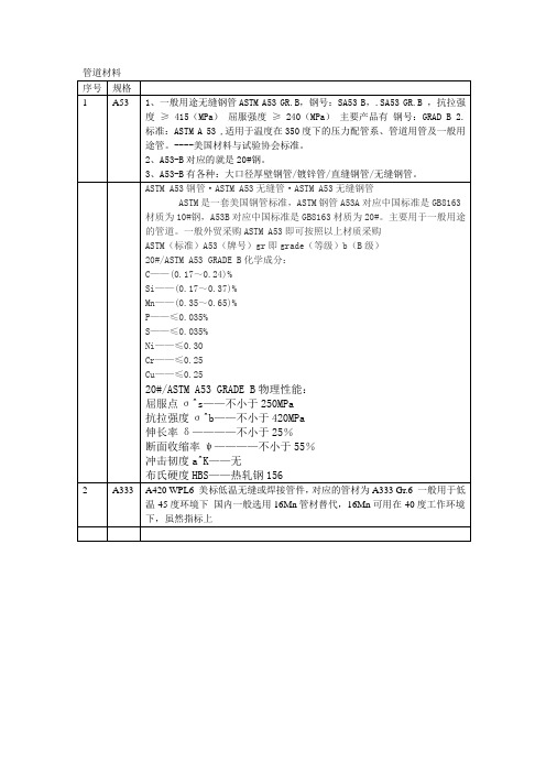
astm a53 对应国内标准ASTM A53 对应国内标准简介ASTM A53 是美国材料和试验协会(ASTM)制定的用于焊接和无缝碳钢管的标准规范。
该标准规定了钢管的机械性能、化学成分等要求。
在国际贸易和工程项目中,ASTM A53被广泛应用。
国内对应标准在国内,ASTM A53 的对应标准为GB/T 3091 和GB/T 3092。
GB/T 3091•GB/T 3091 标准规定了焊接和无缝冷轧钢管的要求。
•该标准适用于民用建筑、结构、通风和水泥输送等领域中的低压流体输送。
GB/T 3092•GB/T 3092 标准规定了焊接和无缝热轧钢管的要求。
•该标准适用于民用建筑、结构和通风等领域中的高压流体输送。
区别和注意事项•ASTM A53 与GB/T 3091/3092 标准有明显的区别,主要体现在材料的化学成分和力学性能要求上。
•在选用钢管时,需根据具体需求和使用环境选择符合标准的钢管。
•在进行国际贸易时,需要特别注意对标准的了解,以确保生产和使用的一致性。
•ASTM A53 和GB/T 3091/3092 标准都有严格的质量检测要求,使用者应遵循相应的检验方法和程序。
结论ASTM A53 是一项重要的国际标准,对应国内的标准为GB/T 3091 和GB/T 3092。
了解这些标准的区别和应用范围,有助于正确选择和使用合适的钢管,确保工程质量和安全性。
以上是关于ASTM A53 对应国内标准的简要介绍,希望对读者有所帮助!注:本文中所提及的标准仅供参考,请在具体使用和选用过程中咨询专业人士或参考更详细的规范文件。
ASTM A53 对应国内标准1. 简介ASTM A53 是美国材料和试验协会(ASTM)制定的用于焊接和无缝碳钢管的标准规范。
该标准规定了钢管的机械性能、化学成分等要求。
在国际贸易和工程项目中,ASTM A53被广泛应用。
2. 国内对应标准在国内,ASTM A53 的对应标准为GB/T 3091 和GB/T 3092。
美标无缝钢管简介美标无缝钢管是一种常用的管道材料,其符合美国标准的制造和质量要求。
无缝钢管是指一种不经过焊接工艺的钢管,具有内外表面光滑,尺寸精确,耐高温和压力的特点。
美标无缝钢管广泛用于石油、天然气、化工、电力、冶金等行业。
优点1.高强度:美标无缝钢管具有良好的强度,能够承受高压和高温的环境。
2.耐腐蚀性:由于无缝钢管没有焊接接头,因此具有较好的耐腐蚀性能,在各种介质中都能保持稳定的性能。
3.尺寸精准:美标无缝钢管采用先进的生产设备和精确的制造工艺,确保管道的尺寸精确,符合相关标准要求。
4.高可靠性:无缝钢管经过严格的产品测试,具有高度可靠性,能够在各种恶劣环境下使用,保证运行的稳定性和安全性。
5.容易安装和维护:美标无缝钢管安装简便,并且维护成本低,能够提高工作效率。
主要用途美标无缝钢管广泛应用于以下行业:•石油工业:用于石油开采、输送及储存。
•天然气工业:用于天然气开采、输送和加工。
•化工行业:用于化工设备和管道系统。
•电力工业:用于发电厂的输送管道。
•冶金工业:用于冶金设备和管道系统。
规格与标准美标无缝钢管的规格和标准根据不同的需求而定,以下是一些常用的规格和标准:•美国石油学会(API)标准:API 5L,API 5CT等。
•美国材料和试验协会(ASTM)标准:ASTM A53,ASTM A106,ASTM A333等。
•美国国家标准学会(ANSI)标准:ANSI B36.10,ANSI B36.19等。
•其他标准:JIS, DIN, GB等。
根据不同的规格和标准,美标无缝钢管的外径、壁厚、长度等参数也会有所不同,可根据具体需求进行选择。
生产工艺美标无缝钢管的生产工艺通常有以下几种:1.热轧:利用热轧机对钢坯进行加热,然后通过多道次的穿孔、挤压等工序形成管子。
这种工艺生产的无缝钢管具有高度的一致性和完整性。
2.冷拔:将热轧的钢管进行进一步加热,然后通过拉拔机将钢管拉制成不同尺寸的无缝钢管。
ASTM A 53/A 53M—05管, 钢材,镀黑和热镀锌,镀锌涂层, 焊接和无缝的标准规范(译文中数字表格是根据A53 / A53M – 01 版粘贴的,不是根据05版贴的)本规范以固定标号A53/A 53M出版发行, 紧跟规范编号的数字表明最近第一次采用该规范的年份, 若规范有修订, 则为最后一次修订的年份, 中间括号内的数字表明最后批准的年份, 标在右上角的小数字表明最后一次修订或批准后的编辑校正。
本规范授权国防部的机构使用。
1. 范围:1.1 本规范涵盖从NPS1/81 本规范涵盖从NPS1/8到NPS26(DN6-DN650)(注1)的无缝和焊接钢管,热镀锌钢管,包括表X2.2和表2.3中所提到的具有名义壁厚的管(注2), 如果这种管与本规范中的所有其他要求一致, 则可以提供其他尺寸的管.注1. 无量纲标记NPS(管的名义尺寸)(DN:名义直径),在本规范中用传统术语:”名义直径”,”尺寸” “名义尺寸”来代替.注2. 术语 “名义壁厚”是为了方便标记,仅是一个名称而已,用于与大于或小于名义壁厚的各种各样的有确切壁厚的管相区别.1.2 本规范涵盖以下类型和等级的管:1.2.1 F型—高温对接焊,连续焊接,A级管1.2.2 E型—电阻焊接, A级 和B 级.1.2.3 S型—无缝焊接, A级和B 级.注3. 见附录X1各类型管的定义.1.3 本规范项下的钢管可供机械动力和压力操作使用,同时也可以用作蒸汽管道,水管道,油管道, 以及通气管道. 这种管适于焊接,定型操作包括卷绕,弯曲,卷边, 但是受下列条件限制: 1.3.1 F型的管不适于卷边.1.3.2 如果要求对S型或者E型管进行封闭卷绕或者冷弯曲, 那么A级是最好的选择. 然而,这并不表明B级管不能冷弯曲.1.3.3 E型管可由生产商来自行选择非扩径或冷扩径操作.1.4 无论是SI单位还是英寸-英镑单位中,它所描述的值都是独立于标准的.每一个单位系统所描述的值不可能正好相等; 所以每个单位系统应该独立使用.1.5 下列防御性的警告仅针对于试验方法部分. 即本规范的第7,8,9,13,14和15节. 本标准没有指出 所有注意安全事项, 如果有,也是只与其用途有关. 本标准的使用者有责任在使用前指定充分的安全健康措施和确定规章制度的适用范围.1.6 本规范的正文包括注或脚注或者同时具备两者来提供注释材料, 这些注和脚注(表中的图表中的除外)不涉及任何强制性要求.2 参考文件2.1 ASTM 标准 :(3)A90/90M 有镀锌或者锌合金涂层的钢和铁制品的涂层的重量(质量)的测试方法A370 钢制品的机械测试的测试方法和定义A530/A 530M 特殊碳和合金钢管的一般要求和规范A700 运输钢制品的包装,标记和装运方法.A751 钢制品的测试方法,操作及化学分析术语.A865 用于钢管连接中的螺纹连接,钢,镀黑或者镀锌焊接或者无缝焊接的规范.B6 对镀锌的规范E29 在测试数据中通过有效数字确定符合规范的操作E213 金属管的超声波测试的操作E273 焊管的焊接区域的超声波测试的操作E309 利用磁饱和对钢管的涡电流测试的操作E570 强铁磁性的钢管制品的磁漏测试的操作E1806 确定钢铁的化学成分的取样的操作表1 化学要求 (翻译内容见英文版本)2.2 ANSI 标准 ASC X 12 (4次方)B1.20.1 螺纹管, 一般规则2.3 ASME 标准 焊接和无缝精练钢管2.4 生产标准MIL-STD-129 运输和储存标识MIL-STD-163 轧钢厂对于成品的运输和储存的准备工作2.5 联邦标准Fed. Std. No123 运输标识(国内代理)Fed. Std. No183 钢铁制品的可持续的身份标记2.6 API 标准5B 车螺纹, 测量和铸造的螺纹检验,制管和管螺纹的排列.注释1) 本规范在美国ASTM委员会A01主管钢, 无缝钢及相关合金的委员分会的权限内,并由主管碳钢管制品的分会A01.09直接负责.当前版本批准: 2005.10.1 发行: 2005 原始批准: 1915 上一次编辑批准: 2004 为A53/A53M-04a2) 关于ASME 锅炉和压力容器代码的申请, 请参阅SA-53第二节的相关规范.3) 关于ASTM 标准参考, 请登陆ASTM网站: .或者ASTM 客服中心service@ . ASTM标准的年度手册信息,参考ASTM网站的标准文件这一网页.4) 可以从美国国家标准委员会(ANSI)得到, 25w, 43rd st.,4th floor, new york, NY 100365) 可以从机械工程师美国协会(ASME)得到, international headquarters, three park ave,. newyork, NY 10016-50986) 可从标准文件制订组,订单组得到, DODSSP, bldg, 4 section D, 700 robbins Ave, PhiladelphiaPA 19111-50987) 可以从服务管理处得到, Washington, DC 204058) 可以从美国石油协会(API)得到, 1220, L, ST, NW, Washington DC 200053 订单信息3.1 若适用,可以考虑将信息条款包括在下列订单内容里面:3.1.1 规范标识( A53 或者A53M, 包括发行年份)3.1.2 数量( 英尺,米或者长度个数)3.1.3 等级(A 或者 B)3.1.4 类型( F, E 或者S, 见1.2)3.1.5 表面处理(镀黑或者镀锌)3.1.6 型号( 或者名义的(NPS), (DN) 和重量等级或者程序编号或者两者; 或者外径和壁厚,见表X2.2 和表X2.3)3.1.7 长度(特定或者任意的, 见16节)3.1.8 端头处理(普通的或者螺纹的, 见11节)3.1.8.1 若有要求, 需要螺纹的或者连接的3.1.8.2 只要螺纹的(不要连接的)3.1.8.3 若有要求, 用普通端头3.1.8.4 若有要求, 连接动力紧固.3.1.8.5 若有要求,锥形丝锥连接NPS2(DN50)或者和更小的管.3.1.9 若有要求,封闭弯曲3.1.10 无缝钢管的非破坏性电子测试(见9.2)3.1.11 证明(见20节)3.1.12 若有要求, 长度的末端作用的报告(见9.2.7)3.1.13 标识(见21节)3.1.14 管的最终用途3.1.15 特殊用途3.1.16 如果与规定的或者MIL-STD-163(见22.1)所适用的不同, 则可选择适用的打包和储存标准和包装标准3.1.17 若需要, 打包和包装标识.4 原料和生产4.1 无缝和焊接管应该通过下列一个或者多个程序生产:平炉, 电炉, 高压氧4.2 如果不同等级的钢连续绞在一起铸造时, 需要对合成物进行鉴定. 钢的生产商应该通过任何指定的程序来排除转换原料以确定各自的等级.℉℃下进行热4.3 等级为B的电阻焊接无缝管应该在焊接完后进行在最低温度1000(540)处理以便没有未回火的马氏体存在,或者两外以这个方式处理以至于没有未回火的马氏体存在.4.4 当管冷胀时,膨胀的部分不应超过规定的管的外径的1.5%.5 化学成分5.1钢材应与表1中要求的化学成分相符合,化学分析应符合试验方法,准则和术语A751.6 产品分析6.1 买方可以对每一批500个根的钢管中的其中两个或者一部分进行分析。
astm a53标准ASTM A53标准是美国材料和试验协会(ASTM)制定的针对焊接和无缝碳素钢管的标准规范。
该标准涵盖了多种管道尺寸和厚度,适用于用于输送气体、液体和其他流体的管道系统。
ASTM A53标准管道通常用于工业和机械领域,以及建筑行业中的供水、供暖和空调系统。
根据ASTM A53标准,管道可以分为类型F和类型E两种。
类型F是无缝管,类型E是电焊管。
这两种管道都要求经过热处理,以确保其力学性能和化学成分符合标准要求。
此外,管道的表面要求应符合ASTM A530/A530M标准中的规定,以保证其外观质量。
ASTM A53标准管道的化学成分要求如下,碳含量不超过0.30%,锰含量不超过1.20%,磷含量不超过0.05%,硫含量不超过0.045%,铬含量不超过0.40%,镍含量不超过0.40%,铜含量不超过0.40%。
这些化学成分的限制可以保证管道的强度、韧性和耐腐蚀性能。
在机械性能方面,ASTM A53标准要求管道的抗拉强度和屈服强度分别不低于330MPa和205MPa。
此外,管道的伸长率也有一定的要求,以确保其在使用过程中不易发生断裂或变形。
除了化学成分和机械性能外,ASTM A53标准还对管道的尺寸和外观质量做出了详细的规定。
管道的尺寸范围从1/8英寸到26英寸不等,壁厚也有多种选择。
管道的外观质量要求表面光滑,无明显的氧化、裂纹和缺陷,以保证其在安装和使用过程中不会出现泄漏和损坏。
总的来说,ASTM A53标准是针对碳素钢管道的一项重要标准,它涵盖了管道的化学成分、机械性能、尺寸和外观质量等方面的要求。
遵循这一标准生产的管道,可以保证其质量稳定,性能可靠,适用于各种工业和建筑领域的管道系统。
ASTMA53标准的制定和执行,对于保障管道安全运行,促进工程建设质量,具有重要的意义。
astm a-53对应国内标准
ASTM A53是美国材料和试验协会(American Society for Testing and Materials, ASTM)制定的钢管标准,适用于供水、气体、蒸汽、空调和供暖等多种用途的普通焊接和无缝碳钢管。
该标准分为
两种类型:类型E(电阻焊接管)和类型S(无缝管)。
在中国,根据ASTM A53标准,国内对应的标准有两个:
1. GB/T 3091-2015,《焊接钢管用螺旋钢管》:这个标准是针
对类型E(电阻焊接管)的ASTM A53管材相对应的国内标准。
它规定
了用于低压流体输送的螺旋焊接钢管的尺寸、外形、重量、技术要求、试验方法、检验规则、标志、包装、运输和质量证明等方面的要求。
2. GB/T 8163-2018,《液体输送用无缝钢管》:这个标准是针
对类型S(无缝管)的ASTM A53管材相对应的国内标准。
它规定了用
于输送石油、天然气和其他液体的无缝钢管的尺寸、外形、重量、技
术要求、试验方法、检验规则、标志、包装、运输和质量证明等方面
的要求。
需要注意的是,虽然ASTM A53和相应的国内标准有很多相似之处,但也存在一些差异。
在使用中需要根据具体的需求和项目要求来
选择合适的标准,并确保符合相关法规和标准的要求。