REFPROP9.1 User's Guide
- 格式:pdf
- 大小:1.01 MB
- 文档页数:62
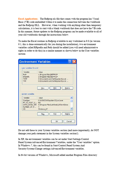
Excel Applications.The Refprop.xls file that comes with the program has Visual Basic (VB) code embedded within it to make the connection between the workbook and the Refprop DLL. However, when working with anything other than temporary calculations, it is best to start with a blank workbook that does not have the VB code. In this manner, future updates to the Refprop program can be made available to all of your old workbooks through the instructions below.To make the Excel routines in Refprop available to any worksheet in 9.0 (in version 9.1, this is done automatically for you during the installation), two environment variables called RPprefix and Path should be added (you will need administrative rights in order to do this) in a similar manner as shown below in the User variables section:Do not add these to your System variables section (and more importantly, do NOT damage your path statement in the System variables section!).In XP, the environment variables can be set under Start/Settings/ControlPanel/System/Advanced/Environment Variables, under the "User variables" option. In Windows 7, this can be found in Start/Control Panel/System AndSecurity/System/Change settings/Advanced/Environment variables.In 64-bit versions of Windows, Microsoft added another Program Files directorycalled "Program Files (x86)", which is the default directory where Refprop gets installed. For the connections to work, you need to either point to this directory in your path statement or copy all the Refprop files to the old "Program Files" directory.The property quality in versions 7 and 8 was assumed to always be given on a molar basis, even though it was labeled as on a mass basis when mass units were in effect (this only affects mixture calculations). The updated file below returns the correct values..Refprop.xls (last updated June 10, 2014)For 64-bit Excel and users of Refprop 9.0, the following file should be placed in your Refprop directory (an updated file comes with 9.1):REFPRP64.DLLIf an error message such as "...is not a valid Win32 application" occurs, try downloading the file again, most likely the file was corrupted during the first attemptWhen you run the new Refprop.exe file, if you get the error message "File not found: REFPROP.DLL", download the 32 bit file below and install it on your machine (double click on the file). If you are connecting Refprop with a 64 bit version of Excel and you get “#VALUE”, download the 64 bit file and install it as well. This also applies to other 64 programs that are connected to Refprop.w_fcompxe_redist_ia32_2011.0.104.msiw_fcompxe_redist_intel64_2011.0.104.msiThe following outlines the procedure for using REFPROP within any spreadsheet in Office 2007 or 2010:1. Open REFPROP.xls and save it as an add-in, REFPROP.xla or REFPROP.xlam, in the main REFPROP folder, C:\Program Files\REFPROP.2. Go to File/Options/Trust Center/Trust Center Settings (button at bottom right).3. Select "Trusted Locations" on the left. Click "Add new location". Browse to C:\Program Files\REFPROP, select "Subfolders of this location are also trusted", and click "OK".4. Go to File/Options/Add-Ins and select "Excel Add-ins" in the Manage drop-down box at the bottom, and click Go.5. Click "Browse", and navigate to C:\Program Files\REFPROP, select REFPROP.xlam and click OK. IMPORTANT: Do not simply select REFPROP.xlam when it first comes up, as this will be in the wrong folder (C:\Documents and Settings\Username\Application Data\Microsoft\AddIns), which is not trusted and will not work.6. Select the Data tab, and click on Edit Links. Select REFPROP.xlam. Click on Change Source and navigate to C:\Program Files\REFPROP. Select REFPROP.xlam there and click OK. (This is just to make sure you are connected to the correct Add-in.) If the Data tab is greyed out, start typing in a Refprop command [such as“=Density(“water”,“TP”,,300,1)] and the button should become active.7. Once you have the xla or xlam file set up, you can open a brand new work book and the functions should be available to you. Do not continue working with the Refprop.xls file since it still contains the VB code that is also in the xlam file. In this manner, future updates from NIST of the Refprop.xls file can be resaved as the xlam file, and all of your work books will have access to the most recent code.Other tips:1. In some cases the macros may not work. Try saving the file as a macro-enabled workbook (under Save As…).2. The xls file distributed with version 9.0 sometimes will give false answers depending on the sequence of calculations if multiple xls files are open. Switching between the open files may cause the initial setup to be lost. The updated xls file given above fixes this.3. For inputs that do not required a 5th parameter, Excel may require the comma at the end, for example: =Pressure("water", "TVAP", "SI", 298,)4. If Excel cannot find the Refprop fluid files, you can copy the *.FLD andHMX.BNC files into a default directory: C:\REFPROP\FLUIDS. When the program fails to find the fluid files, it will look to see if a C:\REFPROP\FLUIDS (or D:) is available, and if so it will use the files from that source.5. If you see dual entries for each function in your workbook, then you have either saved two xla files, or you are working with a file that still contains the VB code. Start with a blank workbook to eliminate the dual entries for the latter case.There have been a number of users who have had problems with the Excel link to Refprop. In some of these cases and in other situations we have found that the refprop.dll file had also been installed in either the c:\windows directory or thec:\windows\system32 directory. If you experience problems, please do a full hard drive search for refprop.dll and delete all occurrences except the one in yourc:\program files\refprop directory.Please send questions to Eric Lemmon: Eric.Lemmon@(If you send a question and do not receive a response within several days, it is quite likely that your email did not make it or that my email was removedby your system administrators as spam or junk mail. I try to respond to allemails within two days, so please write/call again if you do not receive aresponse.)Last modified: Sept. 22, 2014.。
User Instructions for EES_REFPROPREFPROP (Versions 7 and newer, /srd/nist23.htm), developed by the National Institute of Standards and Technology, provides the most accurate thermodynamic and transport property data currently available for pure fluids and fluid mixtures. The property subroutines in these programs have been linked with an interface program called EES_REFPROP to that is callable from EES.INSTALLATIONEES_REFPROP is provided with an installation utility that should guide the installation process. The EES_REFPROP interface package includes the following files.EES_REFPROP.PDF {this file in Acrobat format}EES_REFPROP.FDL {the interface program between EES and REFPROP versions 6 or 7}EES_REFPROP.CHM{help file providing user instructions for the EES_REFPROP interface} EES_REFPROP.TXT {a text file read by EES that sets a number of constants}DFORRT.DLL {a system file needed to run the EES_REFPROP.FDL program} MSVCRTD.DLL {a system file needed to run the EES_REFPROP.FDL program}R134aTST.EES {an EES test file for a pure refrigerant}123-134a.EES {an EES test file for calculating bubble and dew points for a mixture} NARM_ID.EES {an EES test file for performance of a mixed refrigerant heat pump}The EES_REFPROP.FDL, EES_REFPROP.HLP and EES_REFPROP.TXT files should be installed in a folder within the EES32\USERLIB folder. The installation program places these files in the \USERLIB\EES_REFPROP folder. The DFORRT.DLL and MSVCRTD.DLL files will be placed in the WINNT\SYSTEM32 directory (for WINDOW NT/2000/XP) or the WINDOWS\SYSTEM directory (for WINDOWS 95). The installation program will also place instructions and example files in the \EES32\USERLIB\EES_REFPROP directory.EES_REFPROP calls the NIST REFPROP program (version 7 or newer) to do the necessary property calculations. The file that is provided with the REFPROP program that is called by EES is REFPROP.DLL. By default, EES_REFPROP assumes that this file and the \Fluids and \Mixtures folders provided with it can be found in the C:\REFPROP, the C:\PROGRAM FILES\REFPROP or the C:\PROGRAM FILES\NIST\REFPROP directories. If the REFPROP.DLL file is not located in any of these directories, EES will display a "Select Directory" dialog the first time REFPROP is called in which you can identify the location of the REFPROP.DLL file.The EES_REFPROP name should be visible in the Function Info dialog (Options menu) when you select the External Routines radio button. Click on the EES_REFPROP name to select it and then press the Info button to obtain user instructions from within EES.INSTRUCTIONS FOR USING EES_REFPROPThe general format of a property request to EES_REFPROP is:CALL EES_REFPROP('Fluid1+Fluid2', MODE, In1, In2, ... : Out1, Out2, ...)EES_REFPROP will return thermodynamic property information for a specified state, which may include molecular weight, saturation property information, transport properties, fugacity or critical properties depending on the value of the parameter MODE. The required inputs and calculated outputs differ for different values of MODE as explained below.The first argument in the EES_REFPROP Call statement identifies the fluid system which may be a pure fluid or a mixture of up to 5 components. Fluid names are ordinarily the familiar refrigerant names, e.g., R12, R134a, etc. or any mixture name previously defined within the REFPROP program, e.g., R406c. A complete list of fluid names is provided in the REFPROP and manuals. The fluid system name must be must be enclosed within single quotes. A mixture of pure components is identified by use of a plus (+ sign between the component names, e.g., 'R12+R152a'. Upper and lower case letters are treated identically. Spaces should not appear in the fluid system name.The second argument, MODE, is an integer which identifies the calculations to be done and the necessary inputs and outputs. Rather than specify an integer for MODE, however, it is more convenient to use a text code in the form of an EES variable. For example, MODE=12 indicates that thermodynamic properties corresponding to specified inputs of temperature and pressure are to be calculated. It is preferable to use a variable TP (which is set to 12) rather than 12 itself for MODE. The file EES_REFPROP.TXT includes EES variables for each of the modes listed below. To make use of these codes, ensure that the EES_REFPROP.TXT file is in the \EES32\USERLIB\ subdirectory and include the following line at the top of your EES file. $INCLUDE \EES32\USERLIB\EES_REFPROP.TXTEach of the MODES and their associated inputs and outputs are provided below.MODE = MW (=0)Description: Molecular mass of a specified pure fluid or mixtureIn1 = mole fraction of first component in saturated liquid (skip for pure fluid)...InN = mole fraction of next to last componentOut1 = Molecular weightExample:CALL EES_REFPROP('R32', MW : MW_R32)Description: Bubble point calculation for a given temperatureIn1 = Temperature in KIn2 = mole fraction of first component in saturated liquid (skip for pure fluid)...InN = mole fraction of next to last componentOut1 = Pressure of saturated liquid in kPaOut2 = Density of saturated liquid in kmol/m3Out3 = Pressure of saturated vapor in kPaOut4 = Density of saturated vapor in kmol/m3Out5..OutN = Mole fractions of each component in vapor at equilibrium with the liquid Example:CALL EES_REFPROP('R32+R134a',BUBT,300,0.3 : PL,DL,PV,DV,y_32,y_134a) MODE = DEWT (=2)Description: Dew point calculation for a given temperatureIn1 = Temperature in KIn2 = mole fraction of first component in saturated vapor (skip for pure fluid)...InN = mole fraction of next to last componentOut1 = Pressure of saturated liquid in kPaOut2 = Density of saturated liquid in kmol/m3Out3 = Pressure of saturated vapor in kPaOut4 = Density of saturated vapor in kmol/m3Out5..OutN = Mole fractions of each component in liquid at equilibrium with the vapor Example:CALL EES_REFPROP('R32+R134a',DEWT,300,0.3 : PL,DL,PV,DV,x_32,x_134a) MODE = BUBP (=3)Description: Bubble point calculation for a given pressureIn1 = Pressure in kPaIn2 = mole fraction of first component in saturated liquid (skip for pure fluid)...InN = mole fraction of next to last componentOut1 = Temperature of saturated liquid in KOut2 = Density of saturated liquid in kmol/m3Out3 = Temperature of saturated vapor in KOut4 = Density of saturated vapor in kmol/m3Out5..OutN = Mole fractions of each component in vapor at equilibrium with the liquid Example:CALL EES_REFPROP('R32+R134a',BUBP,100,0.3 : TL,DL,TV,DV,y_32,y_134a)Description: Dew point calculation for a given pressureIn1 = Pressure in kPaIn2 = mole fraction of first component in saturated liquid (skip for pure fluid)...InN = mole fraction of next to last componentOut1 = Temperature of saturated liquid in KOut2 = Density of saturated liquid in kmol/m3Out3 = Temperature of saturated vapor in KOut4 = Density of saturated vapor in kmol/m3Out5..OutN = Mole fractions of each component in liquid at equilibrium with the vapor Example:CALL EES_REFPROP('R32+R134a',DEWP,100,0.3 : PL,DL,PV,DV,y_32,y_134a) MODE = TP (=12)Description: Calculate thermodynamic properties for given temperature and pressureIn1 = Temperature in KIn2 = Pressure in kPaIn3 = mole fraction of first component (skip for pure fluid)...InN = mole fraction of next to last componentOut1 = Temperature in KOut2 = Pressure in kPaOut3 = Density in kmol/m3Out4 = Specific volume in m3/kmolOut5 = Specific enthalpy in kJ/kmolOut6 = Specific entropy in kJ/K-kmolOut7 = Quality molar basis(<0 for subcooled liquid, >1 for superheated vapor)Out8= Specific heat at constant volume (Cv) in kJ/K-kmolOut9 = Specific heat at constant pressure (Cp) in kJ/K-kmolOut10 = Speed of sound in m/sec (not applicable for two-phase state)Out11 = Quality mass basis(<0 for subcooled liquid, >1 for superheated vapor)Example:CALL EES_REFPROP('R32+R134a',TP ,300,100,0.3 :T,P,rho,v,h,s,Q,Cv,Cp,w,Qm) MODE = TD (=13)Description: Calculate thermodynamic properties for given temperature and densityIn1 = Temperature in KIn2 = Density in kmol/m3In3 = mole fraction of first component (skip for pure fluid)...InN = mole fraction of next to last componentOut1..Out11: Same as for MODE = TPExample:CALL EES_REFPROP('R32+R134a',TD ,300,13.1,0.3 :T,P,rho,v,h,s,Q,Cv,Cp,w,Qm)In1 = Temperature in KIn2 = Specific volume in m3/kmolIn3 = mole fraction of first component (skip for pure fluid)...InN = mole fraction of next to last componentOut1..Out11: Same as for MODE = TPExample:CALL EES_REFPROP('R32+R134a',TV ,300,0.075,0.3 :T,P,rho,v,h,s,Q,Cv,Cp,w,Qm) MODE = TH (=15)Description: Calculate thermodynamic properties for given temperature and specific enthalpy In1 = Temperature in KIn2 = Specific enthalpy in kJ/kmolIn3 = mole fraction of first component (skip for pure fluid)...InN = mole fraction of next to last componentOut1..Out11: Same as for MODE = TPExample:CALL EES_REFPROP('R32+R134a',TH ,300,39200,0.3 :T,P,rho,v,h,s,Q,Cv,Cp,w,Qm) MODE = TS (=16)Description: Calculate thermodynamic properties for given temperature and specific entropy In1 = Temperature in KIn2 = Specific entropy in kJ/kmolIn3 = mole fraction of first component (skip for pure fluid)...InN = mole fraction of next to last componentOut1..Out11: Same as for MODE = TPExample:CALL EES_REFPROP('R32+R134a',TS ,300,180,0.3 :T,P,rho,v,h,s,Q,Cv,Cp,w,Qm) MODE = TQ (=17)Description: Calculate thermodynamic properties for given temperature and molar qualityIn1 = Temperature in KIn2 = Quality (0 for saturated liquid, 1 for saturated vapor)In3 = mole fraction of first component (skip for pure fluid)...InN = mole fraction of next to last componentOut1..Out11: Same as for MODE = TPExample:CALL EES_REFPROP('R32+R134a',TQ ,300,0,0.3 :T,P,rho,v,h,s,Q,Cv,Cp,w,Qm)In1 = Pressure in kPaIn2 = Density in kmol/m3In3 = mole fraction of first component (skip for pure fluid)...InN = mole fraction of next to last componentOut1..Out11: Same as for MODE = TPExample:CALL EES_REFPROP('R32+R134a',PD ,1000,13.5 ,0.3 :T,P,rho,v,h,s,Q,Cv,Cp,w,Qm) MODE = PH (=25)Description: Calculate thermodynamic properties for given pressure and specific enthalpy In1 = Pressure in kPaIn2 = Specific enthalpy in kJ/kmolIn3 = mole fraction of first component (skip for pure fluid)...InN = mole fraction of next to last componentOut1..Out11: Same as for MODE = TPExample:CALL EES_REFPROP('R32+R134a',PH ,1000,20000 ,0.3 :T,P,rho,v,h,s,Q,Cv,Cp,w,Qm) MODE = PS (=26)Description: Calculate thermodynamic properties for given pressure and specific entropyIn1 = Pressure in kPaIn2 = Specific entropy in kJ/K-kmolIn3 = mole fraction of first component (skip for pure fluid)...InN = mole fraction of next to last componentOut1..Out11: Same as for MODE = TPExample:CALL EES_REFPROP('R32+R134a',PS ,1000,30.0 ,0.3 :T,P,rho,v,h,s,Q,Cv,Cp,w,Qm) MODE = PQ (=27)Description: Calculate thermodynamic properties for given pressure and molar qualityIn1 = Pressure in kPaIn2 = Quality molar basis(0 for saturated liquid, 1 for saturated vapor)In3 = mole fraction of first component (skip for pure fluid)...InN = mole fraction of next to last componentOut1..Out11: Same as for MODE = TPExample:CALL EES_REFPROP('R32+R134a',PQ,1000,0,0.3 :T,P,rho,v,h,s,Q,Cv,Cp,w,Qm)Description: Calculate fugacity for given temperature and densityIn1 = Temperature in KIn2 = Density in kmol/m3In3 = mole fraction of first component (skip for pure fluid)...InN = mole fraction of next to last componentOut1..OutN: fugacity of each fluid in kPaExample:CALL EES_REFPROP('R32+R134a',FUG,300, .075,0.3 :f_32,f_143a) MODE = TRN (=90)Description: Calculate transport properties for given temperature and density In1 = Temperature in KIn2 = Density in kmol/m3In3 = mole fraction of first component (skip for pure fluid)...InN = mole fraction of next to last componentOut1 = Viscosity in μPa-secOut2 = Thermal conductivity in W/m-KExample:CALL EES_REFPROP('R32+R134a',TRN,300,13.1 : Visc, Cond) MODE = CRIT (=100)Description: Calculate critical properties1In1 = mole fraction of first component (skip for pure fluid)...InN = mole fraction of next to last componentOut1 = Critical temperature in KOut2 = Critical pressure in kPaOut3 = Critical density in kmol/m3Example:CALL EES_REFPROP('R32+R134a',CRIT,0.3 : Tc,Pc,rhoc)。


手机应用【PACER】使用说明1.概述 (2)2.跑步 (4)(1) NRC-训练计划 (5)(2) 我的–训练计划 (6)(3) 跑步-5k成绩分组 (7)(4) 跑步画面 (10)(5) 跑步-完赛成绩分组 (11)(6) 跑步-自由设定配速 (12)(7) 跑步-无配速计划 (12)(8) 跑步-路线 (13)(9) 赛道-马拉松比赛 (15)(10) 比赛画面 (15)3.数据 (16)(1)跑步历史记录一览 (16)(2)跑步结果的操作按钮 (16)(3)统计图形 (17)4.工具箱 (17)5.信息 (18)5.1一般设置 (19)5.2批量导入导出 (23)5.2.1 Garmin导出例 (23)5.2.2 iOS用手机导出例 (24)5.2.3 iOS用手机导入例 (25)5.2.4 iOS用iTunes导入例 (26)5.2.5安卓版操作例 (27)6.Pacer生成的GPX文件,导入其他软件 (27)6.1 Garmin导入例 (27)6.2不同软件对同样GPX的处理结果例子 (29)6.3 Garmin导出的数据,再导入Garmin的例子 (29)7.常见问题 (30)(1)为什么我的手机没有语音提示? (30)(2)为什么本来有语音,突然没有语音了? (30)(3)跑步时,把Pacer APP关闭了,再打开怎么没有结束跑步? (30)(4)跑步时,按“结束“按钮,不能结束跑步? (30)(5)不小心按了“休息“怎么办? (30)(6)在马拉松比赛中,不小心按了“过X公里”,而实际上还没过怎么办? (30)(7)在公路上间歇跑可以用Pacer APP么? (31)(8)数据保存在哪里?换手机了之前的跑步数据怎么在新手机上查看? (31)(9)Pacer App到了后台运行,跑步轨迹丢失了? (31)(10)只对应心率带?可以使用心率手表么? (31)(11)重读心率 (31)(12)GPS准么 (31)1.概述Pacer App为跑步爱好者(Runner)和领跑员(配速员Pacer)而开发。

Process Code Maintenance User Guide Release 14.3.0.0.0Part No. F18720-01May 2019Oracle Financial Services Software LimitedOracle ParkOff Western Express HighwayGoregaon (East)Mumbai, Maharashtra 400 063IndiaWorldwide Inquiries:Phone: +91 22 6718 3000Fax: +91 22 6718 3001/financialservices/Copyright © 2018-2019, Oracle and/or its affiliates. All rights reserved.Oracle and Java are registered trademarks of Oracle and/or its affiliates. Other names may be trademarks of their respective owners.U.S. GOVERNMENT END USERS: Oracle programs, including any operating system, integrated software, any programs installed on the hardware, and/or documentation, delivered to U.S. Government end users are “commercial computer software” pursuant to the applicable Federal Acquisition Regulation and agency-specific supplemental regulations. As such, use, duplication, disclosure, modification, and adaptation of the programs, including any operating system, integrated software, any programs installed on the hardware, and/or documentation, shall be subject to license terms and license restrictions applicable to the programs. No other rights are granted to the U.S. Government.This software or hardware is developed for general use in a variety of information management applications. It is not developed or intended for use in any inherently dangerous applications, including applications that may create a risk of personal injury. If you use this software or hardware in dangerous applications, then you shall be responsible to take all appropriate failsafe, backup, redundancy, and other measures to ensure its safe use. Oracle Corporation and its affiliates disclaim any liability for any damages caused by use of this software or hardware in dangerous applications.This software and related documentation are provided under a license agreement containing restrictions on use and disclosure and are protected by intellectual property laws. Except as expressly permitted in your license agreement or allowed by law, you may not use, copy, reproduce, translate, broadcast, modify, license, transmit, distribute, exhibit, perform, publish or display any part, in any form, or by any means. Reverse engineering, disassembly, or decompilation of this software, unless required by law for interoperability, is prohibited.The information contained herein is subject to change without notice and is not warranted to be error-free. If you find any errors, please report them to us in writing.This software or hardware and documentation may provide access to or information on content, products and services from third parties. Oracle Corporation and its affiliates are not responsible for and expressly disclaim all warranties of any kind with respect to third-party content, products, and services. Oracle Corporation and its affiliates will not be responsible for any loss, costs, or damages incurred due to your access to or use of third-party content, products, or services.ContentsProcess Code Maintenance . . . . . . . . . . . . . . . . . . . . . . . . . . . . . . . . . . . . . . . . . . . . . . .4 Initiate Process Code Maintenance (4)Reference and Feedback . . . . . . . . . . . . . . . . . . . . . . . . . . . . . . . . . . . . . . . . . . . . . . . . . .8 References (8)Documentation Accessibility (8)Feedback and Support (8)Process Code Maintenance Process code maintenance enables the user to set the process code to the individual stages according to the process. In the subsequent steps, let's look at the details for creating a process code:Initiate Process Code Maintenance1. Using the entitled login credentials for registration stage, login to the application.2. Click Core Maintenance > Product Code Maintenance on the left pane of the application.3. ClickPlus Icon to create a new process code.4. Provide process code details based on the description provided in the following table:Click Add Rowto capture the stage details that needs to be mapped to the process code as per the description the following table:FieldDescription Sample Values Process Code Provide an unique abbreviation for the processname.The code must be an alphanumeric text withlength of maximum 10 character.Process Name Provide the process name.Application CategoryCodeProvide the version of the process.FieldDescription Sample ValuesStage IDProvide an unique ID for the stage.Stage Description Provide the description of the stage.Field Description Sample Values Seq Order The sequence order identifies the order of thestage in the complete process.Registration must be first in sequence order.Source Stage Enables to identify if the particular stage is thestarting point of the process.IndexPProcess Code MaintenanceInitiate Product Code Maintenance (4)Product Code Maintenance (4)Reference and Feedback ReferencesFor more information on any related features, you can refer to the following documents:● Getting Started User Guide● Common Core User GuideDocumentation AccessibilityFor information about Oracle's commitment to accessibility, visit the Oracle Accessibility Program website at /pls/topic/lookup?ctx=acc&id=docacc.Feedback and SupportOracle welcomes customers' comments and suggestions on the quality and usefulness of the document.Your feedback is important to us. If you have a query that is not covered in this user guide or if you still need assistance, please contact documentation team.。

November 2017Setting up the OPOS Driver for Retail Ariva ScalesThe purpose of this document is the following:1.To give the Big Picture View.2.To document the OPOS Installation Instructions on a Windows machine.3.To document Programming to the OPOS Driver4.To document Configuring the OPOS Driver5.To document Using the OPOS Admin Tool to Test Scale Communications6.To document Debugging POS + OPOS Integration7.Errors: how to handle exception cases.Big Picture View1.Installing this OPOS driver on a Windows machine will, through the Windows registry, make thedriver available for connection.2.This OPOS driver is based on OPOS Standard 1.11.000.3.Three Dynamically Linked Libraries (.dll's) are provided to provide access to the OPOS driver.o One .dll for each of the following: Serial, Ethernet and USB Virtual Com Ports.▪The Ariva does not support Ethernet.▪The Ariva may in the future provide OPOS access via USB HID.o The "EUS" in MTOPOS-EUS Driver stands for "Ethernet, USB and Serial."4.The installation package also installs an Admin program called MTOPOSAdmin.exe.o See below for execution instructions.o The MTOPOSAdmin program allows you to setup and test the OPOS driver.5.To uninstall the driver, uninstall MTOPOS-EUS Driver from the Control Panel.OPOS Installation Instructions1.Download the MTOPOS-EUS Install Release YYYYMMDD.zip package into a new folder on thetarget Windows machine.2.Extract/ unzip the files in MTOPOS-EUS Install Release YYYYMMDD.zip into a new folder (thedefault folder name will typically be MTOPOS-EUS Install).3.The MTOPOS-EUS Install folder will contain the folder "MTOPOS-EUS Install" and under it the"Release" subfolder. Within the Release folder are the following:4.Double-click on setup.exe to start the install process.5.Follow the installation script instructions, allowing the installation of the OPOS Driver and theAdmin tool.a.When running the installer, be sure to select “Everyone” on the second installerscreen (bottom left).6.The install script should complete the following actions:o Install and register the OPOS driver.o Install the .dll's (Serial, USB and Ethernet.)o Install the Admin program (used for testing).o Place a shortcut to the Admin program on the desktop.o Add the Admin program to the Start menu: All Programs | Mettler Toledo | MTOPOS-EUS Driver.Programming to the OPOS Driver1.The OPOS driver will typically be installed on a POS.a.The OPOS driver will be accessed from the POS source code though the .dll's.b.In this implementation, the .dll's contain the actual "drivers".i.There is no separate .sys driver with this OPOS implementation.2.Serial, USB and Ethernet .dll's:a.There are three DLL's that are installed as part of the MTOPOS-EUS software package.i.MettlerScalesSerial.dll:1.Supports Ariva RS-232 Serial communications.ii.MettlerScalesUsb.dll :1.Supports USB Virtual COM Port communications.2.Ariva does not yet support standard HID via OPOS.iii.MettlerScalesEthernet.dll:1.Ariva does not support Ethernet.b.The .dll's are located here: C:\Program Files (x86)\Common Files\MTOPOS Shared.c.These .dll's provide the OPOS driver API's.i.The POS provider software links to these .dll's for OPOS communications.ii.These .dll's hide the details behind Serial, USB and Ethernet communications.3.This OPOS driver does not support "Live Weight" reporting.a.Live Weight is the continuous (non-polling) reporting of weight.b.The Admin tool defaults to continuous weight reporting, but that is because the Admin tooldoes continuous polling.4.Mettler Toledo Retail may be able to provide sample programs for POS programmers to betterunderstand the .dll interfaces.Configuring the OPOS Driver1.For the OPOS driver to work correctly, the Windows OS Registry must be configured on the PC/POS to match the settings of the specific scale being addressed.2.The POS program can set these Registry values or the Admin tool below can be used to set thesevalues.a.For testing, the Admin program can be used to set these values.b.For POS software that is to be widely distributed, the POS program should set these values.3.In particular, the following Registry settings must be set:a.Scale Model = "Ariva".b.Scale Units = [g, kg, oz, lb] as defined by OPOS Standard:i.SCAL_WU_GRAM 1=gii.SCAL_WU_KILOGRAM 2=kgiii.SCAL_WU_OUNCE 3=oziv.SCAL_WU_POUND 4=lbc.Notes on Scale Units:i.The values “lb”, “kg”, “oz” or “g” are set in the registry for Scale Units.ii.The OPOS driver then converts these weight units to its number equivalent and returns the value (0, 1, 2, 3, or 4) as required by OPOS.4.The POS OS Registry (using regedit) should look something like this (note that I am using COM4and kg):Using the OPOS Admin Tool to Test Scale Communications1.Execute the OPOS Admin Tool:a.Connect your Ariva scale to your PC or POS system.i.For RS-232 use cable #72256235ii.For USB Virtual Com Ports use cable #72256236b.The Viva scale uses the Viva RS-232 cable and might require a Null Modem.e the desktop icon or:i.See the next point before running the Admin program!ii.Start->All Programs->Mettler Toledo->MTOPOS-EUS Driver->MTOPOSAdmind.Do not "Run as Administrator" the Admin program.i.I.e., before running the Admin program, right-click on the Admin Program andselect the Properties option.1.This will bring up the "MTOPOSAdmin Properties" dialog.2.Select the Compatibility tab dialog.3.Make sure "Run this program as administrator" is not checked.ii.Why? Because if the Admin program works correctly without “Run a sAdministrator” elevated privileges then the POS program should also work withoutadministrator privileges.2.Once opened, click on “Add Configuration”.3.“Add Configuration” will take you to the Scale Properties page.4.The Admin program can handle multiple scales. Input the following fields:a.Scale Instance:i. A specific scale name. Any name that uniquely identifies the scale is OK.b.Scale Model:i.For Checkout scales select either Viva or ARIVA.c.Protocol:i.The only choice is Toledo (also known as 8217).ii.This is true for both RS-232 and USB Virtual Com Ports.d.Display Weight Units:i.Select Lb., Kg or Oz (must match your scale weighing units).e.Serial Port Settings:i.Note: Ariva scales are factory configured for either RS-232 or USB Virtual COMPorts.1.If you wish to change the Ariva communication mechanism, please refer tothe Ariva User's Guide, Section: Setup, Menu item 3.1 (CommunicationType).ii.Port:1.If scale is using RS-232 (using cable #72256235):a.Typically = COM1 on a PCb.For POS systems please check: Start->Control Panel->View devicesand printers to determine the COM port.2.If scale is using USB Virtual COM ports (using cable #72256236):a.First connect the scale to the PC/ POS.b.Check Start->Control Panel->View devices and printersi.Find METTLER TOLEDO Ariva (COM4)1.>>Could be other port than COM4<<iii.Baud Rate = 9600iv.Data Bits = 7v.Parity = Evenvi.Stop Bits = 15.Note: If necessary, see separate instructions for installing the Virtual COM Port Driver on yourPC/ POS system.a.OPOS and Virtual COM port drivers are separate, distinct drivers.6.Click OK.a.Taking you back to the main screen.Test Scale CommunicationNote: See the Errors section below if you encounter any difficulties.1.Click "Open Connection"2.Weight values will be shown automatically.Other Functions1.The following functions are supported for the Ariva scale:a.Zero Scalei.Zero the scale.b.Tare Scalei.Tare off a weight value.ii.The resulting weight will be a Net Weight.c.Clear Tarei.Clear (zero) the previously set Tare.d.Enable/ Disable Auto Weight Updatei.Click “Disable Auto W eight Update” button to enable the "Read Weight" button.1.And disable automatic weight readings.ii.Click “Enable Auto Weight Update” button to enable automatic w eight readings.Debugging POS + OPOS Integration1.For debugging, a log file is available via the Admin program.o As well as different levels of logging verbosity.o See "Log Settings" on the Admin program main page.o The OposAdmin.log file is located here: C:\ProgramData\Mettler Toledo2.This debugging also works for POS + OPOS integration testing.a.Simply set debugging ON as well as the level of verbosity.i.Then exit the Admin program and run the POS software.b.Extract the debugging log file and send to MT for analyses.3.Remember to turn off the debug flag (via the Admin program) when done debugging.a.I.e., the debugging flag should be turned off for normal OPOS operations.ing debugging flag with POS has not been tested yet.ErrorsPossible Errors (to date):1."Get scale software version failed. Error: OPS_E_TIMEOUT (112)"a.Make sure the scale is connected to the PC/ POS system.b.Make sure the PC/ POS system RS-232/ Virtual COM Port parameters match the scaleparameters (Ariva menu items 3.1 – 3.6).2.Incorrect weight reading:a.Make sure the Weight Units selected above (Lb. Kb, Oz) matches the scale weighing units.3.OPOS driver does not return a valid weight unit with the ReadWeight() command.a.Error example: "Invalid Weight Unit of Measure"b.This typically indicates that either 1) the Admin program did not work correctly or 2) thePOS program is not setup correctly.c.Here are some things to check:i.If the Admin program displays errors then please provide MT with screenshots ofthe errors (with details opened up).ii.If the POS program runs with errors then please provide MT with screenshots of the errors (with details opened up).iii.Please check the UAC (User Access Control) settings on the POS system.1.Having the POS locked down with very strong UAC settings or othersecurity (such as group policy controls) could cause problems.iv.V erify that the database “OPOSAdmin.mdb” is properly located under the“C:\ProgramData\Mettler Toledo” directory.v.Verify that “Everyone” was selected on the second installer screen (above).vi.If the POS program is "Run as Administrator" does this solve the problem?1.Not that we expect to run the POS program as Administrator, but forintegration testing this check answers an important question.d.Also: check the POS systems registry rights:i.Run "regedit" from the Windows "Run" window1.Navigate to the key path:“HKEY_LOCAL_MACHINE\SOFTWARE\Wow6432Node\OLEforRetail\ServiceOPOS\Scale”2.Highlight and right-click on the Scale key.3. A popup menu list should be displayed.4.Select the “Permissions…” option.5.The "Permissions for Scale" window should be displayed.6.Under the Security tab the “Group or user names:” list should have the“Everyone” group displayed at the top.7.Make sure “Everyone” is selected at the top of the list and then click on the“Advanced” button.8.The “Advanced Security Settings for Scale” window should be displayed. Ifthere is no “Everyone” group showing in either the Permissions or theAdvance Security Settings for Scale windows then this is a problem.a.Perhaps something failed in the install process.9.See the two screens below for correct settings.e.Questions for the POS developer:i.Do the other OPOS devices work correctly without elevated privileges?ii.Do the other devices need to access the Windows Registry or is their configuration information passed to them another way (such as through XML or INI files)?iii.What are the user rights associated with the user trying to run the POS program?iv.Does the POS program have a display screen or does it run in the background without a user account association?。
在EXCEl2010中直接调用NIST REFPROP的设置方法网上已经有很多在EXCEL中调用NIST REFPROP的设置方法,但是方法比较过时,本人也是试了好久才成功调用,先把主要步骤做下总结,现在电脑很多都是win8及win10的64位系统,所以针对64位的win10系统的安装方法声明:1、为了保证安装成功,希望严格按照安装步骤进行;若安装完成遇到错误,对相应步骤调整即可。
2、由于nist软件本身是32位软件,所以无论你怎么设置安装路径,都是C:\ProgramFiles (x86)\REFPROP下。
D盘没有试过一、建立环境变量打开“开始/控制面板/系统/高级系统设置/高级/环境变量”,如下图所示。
新建一个环境变量,变量名=RPprefix,变量值= C:\ Program Files (x86)\Refprop点击确定;二、建立EXCEL加载项1、打开REFPROP安装文件夹下的Excel文件REFPROP.xls。
2、按“Alt+F11”键,打开VB编辑器(或者按开发工具/VB编辑器)。
3、打开右边Module,找到如下内容按“Ctrl+F”查找“Refprop.DLL”,并将其全部替换为"C:\Program Files(x86)\Refprop\Refprop.DLL”,保存,并退出Excel。
4、修改Refprop.DLL 中Declar为Declare PtrSafe 这一步比较关键有可能影响能否调用成功三、保存REFPROP为MicrosoftOffice加载项打开第2步保存的REFPROP.xls文件“另存为……”,选择文件类型“Excel加载宏(*.xlam)”,默认的文件地址会变为“...\Microsoft\AddIns”,保存。
若未出现默认地址,在C盘搜索“*.xlam”,找到其所在文件夹,将保存的“REPROP.xlam”文件拷贝到该文件夹。
四、添加加载项AddIns打开一个空白Excel文件,在“文件/选项/加载项”中添加和激活“REFPROPAddIns”,确保其处于激活状态。
Powerful industrial time-series and A&E data collection for on-premise and cloud-based storage & analysisBest-in-class Historian from edge to cloud with data analysis in context Proficy Historian from GE Digital is a best-in-class historian software solution that collects your industrial time-series and Alarms & Events (A&E) data needed to analyze asset and process performance, so you can drive greater business value.The emergence of cloud-based Industrial Internet of Things (IIoT) and big data solutions has spurred continued investment in our Historian. With decades of experience and thousands of successful customer installations around the world, Proficy Historian changes the way companies perform and compete by making data useful.The new Proficy Historian 9.0 enhances usability, configurability and maintainability with significant architectural improvements. Version 9.0 features a completely simplified collector installation process, new collector configuration UX, centralized admin of remote collectors, and remote configuration and management of cloud collectors. Version 9.0 also further enables enterprise-scale deployments, supports on prem / third-party cloud data models, provides an OPC UA server, and more.01Achieve data analysis in context foroptimization & continuous improvementWith Proficy Historian, users can analyze data in context via ProficyOperations Hub and the Historian Analysis run-time application, whichare available for license at no additional cost with Proficy HistorianStandard and Enterprise versions. The combination of Proficy Historianand Proficy Operations Hub provides a powerful data managementsolution with asset model context and visualization. Users receive dataaggregation across multiple sources or historians, ability to define anasset model including tag mapping, and advanced trend analysis. ProficyHistorian also includes an Excel Add-In for Proficy Operations Hub,enabling users to query historical data based on the asset model.02Improve data security & enable enterprise-wide industrial data managementWith data security as our highest priority, Proficy Historian offerscommon and shared User Account Authentication (UAA). Integratedwith LDAP, this feature eases security, allowing users to choose thecommon UAA deployed by other products in their application.Additionally, for enterprise-wide deployments, Version 9.0 features anew model for cross-enterprise data access, cloud-like elasticcomputing on prem, and scalability to 100 million tags.03Simplification, ease of use, reduced costsProficy Historian installs in minutes and offers a small footprint yetscales to support hundreds of users across an enterprise. This newversion significantly simplifies the collector installation process, deploysthe new Remote Collector Manager on each server when collectors areinstalled, provides a new HTML5-based configuration and managementapp, and introduces collector support for compression over the wire,useful for low bandwidth or metered connections by reducing bytesover the network by about 80%.04Faster configuration and easyconnectivity for IoT applicationsConnect to your machine data with an existing collector or build yourown using our SDK. Version 9.0 supports MQTT end points andenhanced hybrid on-prem/cloud data models with the ability to selectdata, frequency, and rate of change, all while leveraging GE Digital’s richdata aggregation and collection capabilities. Collectors can send data toyour local Historian or to cloud-based Predix, AWS, Google, and Azureapplications. Furthermore, this new version includes an optionallyinstalled OPC UA server that supports HDA, DA, installation on a servernode or separate machine, and password and certificate-based security.Outcomes•Achieve fast time to value with simple installation and easy-to-use web clients with integrated tag searching and drag-and drop features •Secure-by-design data collection and storage•Small, powerful footprint, scaling from small applications to hundreds of users and 100 million data points / tags•Take advantage of data analysis in asset model context with the time-saving trend analysis card•Support high availability with data redundancy•Leverage continuous and highly scalable data read and write functionality•Central management of remote data collectors to reduce maintenance costs and downtime Proficy Historian offers simple configuration with proven industrial data management capabilities to reduce costs and speed deployment.HervéHusson, Automation and Industrial IT (A2i)Manager, Terreal“Proficy Historian is the heart of the [system]. This solution allows more accurate data to be implemented in real time for each machineand product.”Powerful industrial time-series and A&E data collection for on-premise and cloud-based storage & analysisFeatures•Collects industrial data at very high speed, normalizes data and stores it securely, distributes,and allows for fast retrieval and analysis•24/7 availability: avoid downtime and information gaps; stability and reliability for continuousimprovement data analysis as well as mission-critical applicationsNew in Version 9.0•Dramatic simplification of collector installation and management: completely simplified collector installation process, new collector configuration UX, centralized admin of remote collectors, remote configuration & management of cloud collectors•Enterprise-scale deployments enhancements: new model for cross enterprise data access, cloud-like elastic computing on-prem, scalable from 100 tags to 100 Million tags•Hybrid on premise / third-party cloud data model: select data, frequency, rate of change; support for MQTT end points•OPC UA server that supports HDA, DA, installation on a server node or separate machine, and password and certificate-based security Proficy Historian: Best-in-class industrial datamanagement that scales to millions of tags•Easily deployable mirrored architecture based onGE’s U.S.-patented highly efficient and securestorage format•Alarms & Events database, allowing retrieval of A&Ein correlation to time-series data•Intelligent system diagnostic engine and dashboard•Browser-based central administrative console andtrend client•Multi-threaded for high performance•Scales from small to millions of tags•Ability to perform complex, multi-site industrialinformation management•Data in context: Proficy Operations Hub Server andHTML5 Historian Analysis run-time applicationavailable for license at no additional cost with ProficyHistorian Standard or Enterprise versions•Native collectors including MQTT collector•Store and forward capability•Historian ETL –Extract, Transfer, Load•Remote Collector Management•High availabilityRequirementsThe following requirements are not comprehensive. Pleaserefer to the online product documentation for requirementsinformation or contact GE Digital related to your application.•Historian Server –May be physical hardware or a VirtualMachine (including VM on the cloud) that is equivalent tothe minimum physical hardware requirements. Forphysical hardware, minimum requirements: 2.4 GHzclock-speed Intel Core i3 or i5 or i7 CPU or equivalentAMD Phenom CPU with 8 GB RAM for a 64-bit HistorianServer; 80 GB free hard-drive space for the data archives,message files, buffer files, and log files used by theSystem; 100 Mbps TCP/IP compatible network interfaceadapter for network communication and certain I/Odrivers.•Operating Systems (64-bit systems only for yourHistorian Server): Windows Server 2019, WindowsServer 2016, Windows Server 2012 R2, Windows 8.1 and10, Windows 10 IoT•Microsoft Excel (32 bit & 64 bit) 2019 , 2016, 2013, 2010•Collectors: Calculation, CygNet, File, iFIX, MQTT, ODBC,OPC, OPC HDA, OPC UA Data Access, OSI PI (& OSI PIDistributor), Server-to-Server, Wonderware. Notes: Tocollect data from CIMPLICITY, you must use the HistorianOPC collector with the CIMPLICITY OPC Server. Seedocumentation for list of Bi-Modal Collectors. Majority ofcollectors can write to cloud.•SQL Server 2012 SP3; SQL Server 2014 SP1 (E/S/P); SQLServer 2016 (E/S/P); SQL Server 2017 (E/S/P), SQL Server2019Hardware and software requirements are partially representativeand may vary by customer deployment. Please consult the productdocumentation for more details.Both your IT department and end users will love the ease of deployment, scalability, simplicity, and speed of getting the data and value out of Proficy Historian.LEARN MOREProficy Historian includes use of Proficy Operations Hub’s Asset Model mapping and Trend Analysis App for centralized data analysis in context.•Highly efficient data compression: collector compression at the source (deadband) and archive compression at the server•Flat or traditional hierarchical architecture; horizontal scalability with distributed server architecture •Secure-by-design storage•S95 model support•Condition-based collection•Server-to-server aggregation•UAA/OAuth2 Java Web Token security model •Predix, AWS, Google, and Azure cloud connectivity •Server-to-Azure IoT Hub Distributor•Cloudera certified method to move and query data in HDFS / Hadoop to Parquet•APIs to track version information of collectors, Query Results API, Write Tag API, Rename API•Public REST API and Java API•One-click configuration with CIMPLICITY and iFIX •Excel Add In•Little to no DB admin required•Support for storage of Future DataPowerful industrial time-series and A&E data collection for on-premise and cloud-based storage & analysisServicesIn the world of Industrial Internet of Things (IIoT), organizations are able to optimize productivity, reduce costs, and achieve Operational Excellence. While this is an exciting time for opportunity and growth, it can also bring on new challenges, questions, and uncertainty. No matter where you are on your IIoT journey, GE Digital has the right services offering for you.Related ProductsGE Digital’s Proficy suite helps you precisely monitor, control,and visualize every aspect of your operations, enabling operators to make the best decisions faster.Advisory Services We can help you plan and start your IIoT journey in a way that aligns to your specific business outcomes.Managed Services We can help you maintain your critical machines from one of our remote locations around the world using model-based predictive analytic technology.Implementation Services Our experienced global Automation partners can implement a collaborative, multi-generational program that marries your existing investments to the right enhancements and cation Services We specialize in education services to ensure that you’re leveraging our solutions to the fullest extent with our training and certificate programs.Acceleration Plans Let us help by ensuring that your business continues to operate at its highest efficiency, all while mitigating risks to your investments.Security Services Our solutions provide industrial-grade security for a wide range of OT network and application topologies.iFIXGain visibility into your operations and secure agility for smarterdecision making that drives results.CIMPLICITYDrive real-time visibility for smart operators with true client-server basedvisualization and control.Proficy Operations Hub A centralized environment for aggregating and visualizing contextual and situational information for industrialapplications –supporting rapid application development & rich displays for faster response.Continue your Digital Transformation journeyTransforming your business requires foundational innovations that lay the groundwork for future success. It requires connecting assets and processes securely to drive operational efficiencies, reduce unplanned downtime and improve performance.Proficy WorkflowGuide operators with dynamic, interactive electronic workinstructions and eSOPs for more consistent operations and optimized processes.GE (NYSE: GE) is the world’s Digital Industrial Company, transforming industry with software-defined machines and solutions that are connected, responsive and predictive. GE is organized around a global exchange of knowledge, the “GE Store,” through which each business shares and accesses the same technology, markets, structure and intellect. Each invention further fuels innovation and application across our industrial sectors. With people, services, technology and scale, GE delivers better outcomes for customers by speaking the language of industry.©2021 General Electric. All rights reserved. *Trademark of General Electric. All other brands or names are property of their respective holders.Specifications are subject to change without notice. 01 2021About GEContact/digitalProficy Plant Applications Maximize overall equipment effectiveness (OEE), improveproduction scheduling, and ensure product quality by leveraging realtime production dataPredixInnovate and transform your business with the cloud-based operating system for the IndustrialInternet, purpose-built for industry.。
NuTool – PinConfigureUser ManualNUTOOL - PINCONFIGURE USER MANUAL用户手册The information described in this document is the exclusive intellectual property ofNuvoton Technology Corporation and shall not be reproduced without permission from Nuvoton.Nuvoton is providing this document only for reference purposes of NuMicro microcontroller andmicroprocessor based system design. Nuvoton assumes no responsibility for errors or omissions.All data and specifications are subject to change without notice.For additional information or questions, please contact: Nuvoton Technology Corporation.Table of Contents1INTRODUCTION (4)1.1SUPPORTED CHIPS (4)2SYSTEM REQUIREMENTS (4)3RUNNING THE NUTOOL - PINCONFIGURE (4)4USER INTERFACE GUIDE (5)4.1GUI Overview (5)4.2Select Field of Chip Series and Part No. (6)4.3MFP Registers TreeView (7)4.4Supported Module - TreeView (8)4.4.1Usage (8)4.4.2Conflict (9)4.4.3Adjustment of Conflicts (10)4.4.4Multiple Selections (13)4.4.5Search (14)4.5Chip View (15)5TOOLBAR (18)5.1Switch Select Field and MFP-Registers TreeView (18)5.2Load Configuration (18)NUTOOL - PINCONFIGURE USER MANUAL用户手册5.3Save Configuration (18)5.4Generate Code (18)5.5Print Report (18)5.6Generate Report of Pin Description (18)5.7Run NuCAD (19)5.8Switch Pin Description (20)5.9Zoom In (21)5.10Best Fit (21)5.11Zoom Out (21)5.12Disable All Checked Modules (21)5.13Settings (22)5.14Read User Manual (22)6REVISION HISTORY (23)List of FiguresFigure 3-1 NuTool - PinConfigure.exe and Related Folders (4)Figure 4-1 PinConfigure Window (5)Figure 4-2 Selecting Part Number (6)Figure 4-3 Editing a MFP Register (7)Figure 4-4 Results of Configuring ACMP0 by the TreeView (8)Figure 4-5 “Conflict Occurred” Dialog Box (9)Figure 4-6 Recursive Adjustment (10)Figure 4-7 "Adjustment of the Conflict" Dialog Box (11)Figure 4-8 Adjustment Based on Removal (12)Figure 4-9 Multiple Selections of BRAKE00 (13)Figure 4-10 Matched Search Results (14)Figure 4-11 List of All the Related GPIO Multi-functions (15)Figure 4-12 Results of Configuring ADC0_7 by the Individual Pin (16)Figure 4-13 Disabling the Configured Pin (17)Figure 5-1 Generated Schematic Unit by NuCAD (19)Figure 5-2 Pin Description Expanded around the Chip (20)Figure 5-3 “Settings” Dialog Box (22)NUTOOL - PINCONFIGURE USER MANUAL用户手册NUTOOL - PINCONFIGURE USER MANUAL用户手册1INTRODUCTIONThe NuTool - PinConfigure is used to configure GPIO multi-functions of Nuvoton NuMicro ® Family. Its features are listed below:● Configuring by the TreeView : All the supported modules are collected and listed in the TreeView. The user can manipulate the tree to configure GPIO multi-functions easily. ● Configuring by individual pins: Configuring GPIO multi-functions by individual pins is allowed. The user can complete their operation more intuitively and efficiently. ● Configuring by editing the register value directly: The user can utilize this feature to inspect the accuracy of the value.●Generation of code or report: After configuring GPIO multi-functions, the user can generate code or print a report. The generated code can be included into the developing projects. The report comprises all the configuration information.Through the application, the user can configure GPIO multi-functions of the NuMicro ® Family correctly and handily.1.1 SUPPORTED CHIPSTo see the list of supported chips, please refer to Supported_chips.htm in the folder of user manual. The alternative way is to click the Read User Manual button on the toolbar.2 SYSTEM REQUIREMENTSThe following table lists system requirements for the user to run NuTool - PinConfigure .● Windows 7 or later operating system. ●Internet Explorer 10 or later.3 RUNNING THE NUTOOL - PINCONFIGURETo run NuTool - PinConfigure, double-click the NuTool - PinConfigure.exe. Note that the .exe file and the related folders, such as the Content folder, should stay in the same directory; otherwise, the application will not work properly.Figure 3-1 NuTool - PinConfigure.exe and Related Folders4 USER INTERFACE GUIDE4.1 GUI OverviewThe PinConfigure Window includes a variety of components. The name of each component is describedin Figure 4-1.NUTOOL - PINCONFIGURE USER MANUAL用户手册Figure 4-1 PinConfigure Window4.2 Select Field of Chip Series and Part No.The user can select the expected chip series and part No. from the upper-left select field (referring toFigure 4-2). If the select field and the MFP Registers TreeView are hidden, please click the Switch SelectField and MFP-Registers TreeeView to show them.NUTOOL - PINCONFIGURE USER MANUAL用户手册Figure 4-2 Selecting Part Number4.3 MFP Registers TreeViewThe current values of MFP registers are displayed in this TreeView. Moreover, the user can edit themdirectly by double-clicking on the expected one and enter a new value (referring to Figure 4-3). Afterediting, the corresponding check boxes of the supported modules - TreeView and the chip view will beupdated immediately. Some chips require two different MFP registers to configure GPIO multi-functions,and thus the user cannot edit the values of MFP registers by double-clicking these chips.NUTOOL - PINCONFIGURE USER MANUAL用户手册Figure 4-3 Editing a MFP RegisterNUTOOL - PINCONFIGURE USER MANUAL用户手册4.4Supported Module - TreeView4.4.1UsageWith the supported module - TreeView, the user can configure the peripheral pin(s). Each time a module or its individual GPIO multi-function is checked in the check boxes, the chip view shown in the right window will display the new state of the pin(s). Besides, the corresponding value of MFP register will be updated at the same time. For example, the user configures ACMP0 and the results are shown as Figure 4-4.Figure 4-4 Results of Configuring ACMP0 by the TreeView4.4.2 ConflictWhen the pins have been configured to a module, the related texts in the check boxes will be markedin red. If the user obliviously wants to configure the pins again through the TreeView, this case is calledas a conflict. A dialog box which lists the relevant pins and their configured modules will be invoked(referring to Figure 4-5). It offers two options to decide the next step. Clicking the Yes button, the toolwill make the adjustment of conflicts. Clicking the No button, the tool will only configure the remainingpins.NUTOOL - PINCONFIGURE USER MANUAL用户手册Figure 4-5 “Conflict Occurred” Dialog Box4.4.3 Adjustment of ConflictsTo resolve conflicts, the tool recursively adjusts configured modules if possible. For instance, if the userwants to configure EPWM1_0, the tool will try to adjust BRAKE01 to another pin (Pin 72). However, Pin72 is occupied by EMAC_MII_MDC. Fortunately, EMAC_MII_MDC has a configurable pin (Pin 70) toconfigure.NUTOOL - PINCONFIGURE USER MANUAL用户手册Figure 4-6 Recursive AdjustmentAs a result, the tool finds the way to adjust the conflict. EPWM1_0 is configured. At the same time,BRAKE01 and EMAC_MII_MDC are kept. A dialog shows up to tell the adjustment details. If the userwants to undo the adjustment of the conflicts, please click the Undo button.NUTOOL - PINCONFIGURE USER MANUAL用户手册Figure 4-7 "Adjustment of the Conflict" Dialog BoxSometimes, the tool could find several modules unable to adjust. For instance, Pin 93 is occupied byACMP0_N. ACMP0_N has only one option (Pin 93). Thus, if the user wants to configure ADC0_7, thetool is unable to adjust ACMP0_N. That is why when configuring ADC0_7, ACMP0_N has to beremoved.NUTOOL - PINCONFIGURE USER MANUAL用户手册Figure 4-8 Adjustment Based on Removal4.4.4 Multiple SelectionsThere are some modules whose GPIO functions have multiple selections of pins to the same function.In this case, the related check boxes are highlighted with the steel blue color. The user is only permittedto select one of pins. For example, in the BRAKE module, its GPIO function of BRAKE00 has twooptions, pin 65 and 73, but only one of them can be occupied by BRAKE00 (referring to Figure 4-9).NUTOOL - PINCONFIGURE USER MANUAL用户手册Figure 4-9 Multiple Selections of BRAKE004.4.5 SearchTo find a specific module in the supported modules - TreeView, the user can input the expected modulename in the search field. After input, the matched texts in the check boxes will be marked in bold anditalics. Note that the search adopts the partial match, not exact match (referring to Figure 4-10). Theminimum number of input characters is two.NUTOOL - PINCONFIGURE USER MANUAL用户手册Figure 4-10 Matched Search Results4.5 Chip ViewThe chip view, which is in the right pane of the window, depicts a graphical chip involving its pins. Eachpin possesses its own information of the current pin assignment. The pins which are highlighted withthe purple color denote that they do not belong to the configurable pins. If a pin is being configured to aGPIO multi-function, the corresponding function name will emerge in the vicinity of the pin. Meantime,the pin will be highlighted with the green color if it is configured by the TreeView, or with the orangecolor if it is configured by the individual pin.To configure by the individual pin, follow the steps below:1. Move the mouse cursor to the expected pin and click on the left button of the mouse. Then thelist of all the related GPIO multi-functions will emerge in the vicinity of the pin (referring toFigure 4-11).2. Move the mouse cursor into the list and select the expected GPIO function and click on it.Configuring by the individual pin is accomplished. At the same time, the TreeView and thevalue of the MFP register will be updated correspondingly (referring to Figure 4-12).The difference between configuring by individual pins and TreeView is that the user can arbitrarilyconfigure any pin by the individual pins without considering the occurrence of a conflict. To disable theconfigured pins by individual pins, move the mouse cursor to the expected pins and left-click. Selectthe last row of the list which is named as Reset (referring to Figure 4-13). Then the disable operationis completed.NUTOOL - PINCONFIGURE USER MANUAL用户手册Figure 4-11 List of All the Related GPIO Multi-functionsNUTOOL - PINCONFIGURE USER MANUAL用户手册Figure 4-12 Results of Configuring ADC0_7 by the Individual PinNUTOOL - PINCONFIGURE USER MANUAL用户手册Figure 4-13 Disabling the Configured PinNUTOOL - PINCONFIGURE USER MANUAL用户手册5 TOOLBAR5.1Switch Select Field and MFP-Registers TreeViewTo show the select field and the MFP Registers TreeView, click the Switch Select Field and MFP-Registers TreeeViewbutton on the toolbar.5.2 Load ConfigurationThe user can browse the previously saved configuration files (*.cfg) and select one of them to restore the configured MCU chip.To load the configuration, click the Load Configuration button on the toolbar, select the directory preserving the expected configuration file and click the Open button.5.3 Save ConfigurationTo save the current configuration, take the following steps: 1. Click the Save Configurationbutton on the toolbar.2.Browse a user-defined location and give a proper name to the configuration file (*.cfg).3. Click the Save button. The current configuration will be saved as a .cfg file with a given name. The configuration file can be used to restore the configured MCU chip in the future.5.4Generate CodeTo generate code to be included into the developing projects, click the Generate Code button onthe toolbar.5.5 Print ReportTo print a report, click the Print Report button on the toolbar. After inputting the project name and selecting the expected criteria, click on the Confirm button to print the report.5.6 Generate Report of Pin DescriptionTo generate report of pin description, click the Generate Report of Pin Description button on thetoolbar.NUTOOL - PINCONFIGURE USER MANUAL用户手册5.7Run NuCADTo run NuCAD, click the Run NuCAD button on the toolbar. NuCAD can generate the OrCAD or Protel library file (.OLB or .LIA) to facilitate the schematic design. The OrCAD requirement of the version should be higher than or equal to 16.2. Altium Designer of the version should be higher than or equal to 10. The generated schematic unit will look like Figure 5-1 If the user wants to include the standard library provided by Nuvoton, please refer to the folder of SchematicLibrary in the same directory as the .exe file.Figure 5-1 Generated Schematic Unit by NuCAD5.8 Switch Pin Descriptiondescription will be expanded around the chip (referring to Figure 5-2).NUTOOL - PINCONFIGURE USER MANUAL用户手册Figure 5-2 Pin Description Expanded around the ChipNUTOOL - PINCONFIGURE USER MANUAL用户手册5.9Zoom InTo adjust the chip view to a larger one, click the Zoom In button on the toolbar. Besides, the user can do the operation by scrolling the mouse wheel up and holding the Ctrl key on the keyboard simultaneously. To horizontally scroll the chip view, please scroll the mouse wheel and hold the Shift key on the keyboard simultaneously.5.10 Best FitTo adjust the chip view to fit the window, click the Best Fitbutton on the toolbar.5.11 Zoom OutTo adjust the chip view to smaller one, click the Zoom Out button on the toolbar. Besides, the user can do the operation by scrolling the mouse wheel down and holding the Ctrl key on the keyboard simultaneously.5.12 Disable All Checked ModulesTo disable all checked modules, click the Disable All Checked Modules button on the toolbar.5.13 Settingssupported in the application, including English, Simplified Chinese, and Traditional Chinese. Besides, ifthe user wants to display a tooltip, please choose “Yes”. When generating code, the user can determinethe criteria by which the configured information is being classified.NUTOOL - PINCONFIGURE USER MANUAL用户手册Figure 5-3 “Settings” Dialog Box5.14 Read User ManualTo read this user manual, click the Read User Manual button on the toolbar.6 REVISION HISTORY日期版本描述2013.10.18 1.00 1. Initially released.2013.11.08 1.01 1. Supported IE9.2. Supported Simplified Chinese and TraditionalChinese.2014.01.03 1.02 1. Supported IE10.2. Improved performance and GUI.3. Added the Search feature.4. Added the Print Report feature.2014.01.24 1.03 1. Supported M451 series.2. Enhanced stability.2014.11.28 1.04 1. Supported IE11.2. 2. Supported NUC100, NUC200, NUC505,NUC029, M051, M0518, Mini51, Nano100,NM1500, ISD9100 and ISD9300.2015.07.01 1.05 1. Supported Mini58 and M0519.2. Added the Tooltip feature.2015.11.01 1.06 1. Added the NuCAD feature.2015.12.01 1.07 1. Added back the Generate Report of Pin Descriptionfeature.2016.02.29 1.08 1. Supported NANO103.2016.07.22 1.09 1. Added new part numbers.2. NuCAD supported Protel.2017.08.01 1.10 1. Supported NUC121, NUC125, NUC126, M0564,and M480.2017.10.20 1.11 1. Supported the adjustment of conflicts. 2018.06.29 1.12 1. Updated the content of M2351 and M480. 2018.07.29 1.13 1. Supported Mini57, NDA102 and NM1120.2018.12.28 1.14 1. Supported NUC2201, M251, and ML51.2. 2. Updated NANO103.2019.04.29 1.15 1. Supported NUC1261, M05641, M4521,NUC029xDE, NUC029xEE, NUC029xGE, MS51,M031 and M261.2019.09.06 1.16 1. Supported MS51(8K/32K),M031(G/I/Keyboard/Mouse), M2353SIAAE andNUC1311.2. Updated M480LD and NANO100BN.2019.11.01 1.17 1. Supported NUC029ZAN.NUTOOL - PINCONFIGURE USER MANUAL用户手册2. Updated M031, M480 and MS51.2020.01.31 1.18 1. Supported M031BT and M479.2020.03.06 1.19 1. Supported ML56, M487KMCAN and NUC029MDE.2020.04.30 1.20 1. Supported M0A21 and M030G.2. Supported a new way of generating code..2020.11.20 1.21 1. Supported M071, M253, M258, M471 and M2354. 2021.03.19 1.22 1. Supported NUC1262 and M030G.2021.06.30 1.23 1. Supported M256D, M258G and KM1M7AF.2022.03.30 1.24 1. Supported KM1M7BF, M460HD, M460LD andMA35D1.2. Update the format with template.NUTOOL - PINCONFIGURE USER MANUAL用户手册NUTOOL - PINCONFIGURE USER MANUAL用户手册Important NoticeNuvoton Products are neither intended nor warranted for usage in systems or equipment, anymalfunction or failure of which may cause loss of human life, bodily injury or severe propertydamage. Such applications are deemed, “Insecure Usage”.Insecure usage includes, but is not limited to: equipment for surgical implementation, atomicenergy control instruments, airplane or spaceship instruments, the control or operation ofdynamic, brake or safety systems designed for vehicular use, traffic signal instruments, all typesof safety devices, and other applications intended to support or sustain life.All Insecure Usage shall be made at customer’s risk, and in the event that third parties lay claimsto Nuvoton as a result of customer’s Insecure Usage, customer shall indemnify the damagesand liabilities thus incurred by Nuvoton.。
NIST Standard Reference Database 23NIST Reference Fluid Thermodynamic and Transport Properties—REFPROPVersion 9.1User's GuideEric W. LemmonMarcia L. HuberMark O. McLindenApplied Chemicals and Materials DivisionNational Institute of Standards and TechnologyBoulder, Colorado 80305April, 2013U.S. Department of CommerceTechnology AdministrationNational Institute of Standards and TechnologyStandard Reference Data ProgramGaithersburg, Maryland 20899The National Institute of Standards and Technology (NIST) uses its best efforts to deliver a high quality copy of the Database and to verify that the data contained therein have been selected on the basis of sound scientific judgment. However, NIST makes no warranties to that effect, and NIST shall not be liable for any damage that may result from errors or omissions in the Database.©2013 copyright by the U.S. Secretary of Commerce on behalf of the United States of America. All rights reserved. No part of this database may be reproduced, stored in a retrieval system, or transmitted, in any form or by any means, electronic, mechanical, photocopying, recording, or otherwise, without the prior written permission of the distributor.Certain trade names and other commercial designations are used in this work for the purpose of clarity. In no case does such identification imply endorsement by the National Institute of Standards and Technology, nor does it imply that the products or services so identified are necessarily the best available for the purpose.Microsoft, Windows, Excel, and Visual Basic are either registered trademarks or trademarks of the Microsoft Corporation in the United States and/or other countries; MATLAB is a trademark of MathWorks.ACKNOWLEDGEMENTSWe gratefully acknowledge the many contributions of our colleagues and associates. Gary Hardin (of NIST) provided support with the help file and the installation package. Allan Harvey (of NIST) provided very thorough and greatly appreciated debugging of REFPROP. Frank Doyle developed the UserInformation sheet in the Excel file. G. Venkatarathnam (of the Indian Institute of Technology Madras) and Matthias Kunick (of the Zittau/Goerlitz University of Applied Sciences, Germany) provided routines and much help in the development of new algorithms for the calculation of VLE states in 9.1, particularly in the critical region. Diego Ortiz (of Texas A&M University), Andreas Jaeger, and Johannes Gernert (both from the Ruhr University, Germany) helped with the analytical VLE routine added in version 9.0. Arno Laesecke (of NIST) provided an extensive collection of viscosity data. Lennart Vamling (of the Chalmers University of Technology in Sweden), Johannes Lux (of the German Aerospace Center), and Paul Brown (of Ramgen Power Systems) aided in the MATLAB link. Chris Muzny (of NIST) aided with the link to C++, and with the MATLAB link.Previous versions of the REFPROP database were developed by Graham Morrison and John Gallagher. Jim Ely, Dan Friend, and Marcia Huber wrote the early versions of the related databases NIST12 and NIST14 from which we have extracted algorithms. We thank Sanford Klein and Adele Peskin, the programmers of the original graphical interface implemented in version 6. We had many helpful discussions with Dan Friend, Allan Harvey, Roland Span, Wolfgang Wagner, Richard Jacobsen, Vincent Arp, Arno Laesecke, Richard Perkins, and Reiner Tillner-Roth.We also made extensive use of the CATS Database for Pure Fluids and Mixtures of the Center for Applied Thermodynamic Studies of the University of Idaho, Moscow, Idaho, the NIST/TRC SOURCE and TDE Databases, the AIChE DIPPR database, and the Dortmund Data Bank for Pure Component Properties (DDB-Pure), Oldenburg, Germany, in fitting the models implemented in REFPROP. Finally, we acknowledge our many colleagues whose property measurements and models we have taken from the literature, and without which this database would be much reduced in scope.Development of this software package was supported by the NIST Thermophysical Properties Division and the NIST Standard Reference Data Program. The development of previous versions was supported by the Air-Conditioning and Refrigeration Technology Institute and the U.S. Department of Energy. Model development and measurements at NIST have been supported over a period of many years by numerous sponsors including the Air-Conditioning and Refrigeration Technology Institute, the U.S. Department of Energy, the Electric Power Research Institute, the Environmental Protection Agency, Oak Ridge National Laboratory, the American Society of Heating, Refrigerating and Air-Conditioning Engineers, and the Building Environment and Thermophysical Properties Divisions of NIST.CONTENTS1. INTRODUCTION (1)1.1 Objectives and Scope of the Database (1)1.2 Uncertainties in Calculated Properties (1)1.3 Organization of the User's Guide (1)2. INSTALLATION (2)2.1 System Requirements (2)2.2 Installation (3)3. OVERVIEW (3)3.1 Database Structure (3)3.2 Use of the Database (3)3.3 Overview of the Menus (3)3.4 Cautions (4)4. DEFINING THE FLUID OF INTEREST (6)4.1 Selecting a Pure Fluid (6)4.2 Selecting a Pseudo Pure Fluid (6)4.3 Selecting a Predefined Mixture (7)4.4 Defining a New Mixture (8)4.4.1 Defining the mixture name and composition (8)4.4.2 Storing a mixture for future use (9)4.4.3 Specifying a fluid set (10)4.5 The Status Bar (10)4.5.1 Pure-fluid information screen (11)4.5.2 Changing property models (12)4.5.3 Mixture information screen (12)4.6 Viewing Mixture Parameters (13)4.7 Changing Mixture Parameters (14)5. GENERATING PROPERTY TABLES (15)5.1 Calculating Saturation Tables (15)5.2 Calculating Iso-Property Tables (18)5.3 Calculating Tables at Specified State Points (19)5.4 Calculating Saturation Properties at Specified Points (21)5.5 Reformatting Existing Data Tables (22)5.6 Warnings and Errors (23)6. CREATING AND MODIFYING PLOTS (25)6.1 Plotting Data from Tables (25)6.2 Overlaying Data onto Existing Plots (26)6.3 Predefined Diagrams (26)6.3.1 Diagrams of thermodynamic surfaces (26)6.3.2 Phase diagrams (28)6.4 Modifying Plots (29)6.4.1 The Modify Plot command (29)6.4.2 Adding and deleting labels (29)6.4.3 Resizing and moving plots (30)6.4.4 Reading coordinates off a plot (30)6.4.5 Zooming (30)6.4.6 Add a point to a table (30)7. CHANGING OPTIONS AND PREFERENCES (31)7.1 Units (31)7.2 Enthalpy and Entropy Reference States and Exergy (32)7.3 Properties Calculated (33)7.4 Property Order (36)7.5 Preferences (37)7.6 Saving Current Options and Preferences (39)7.7 Retrieving Previously Defined Options (40)8. SAVING AND PRINTING (41)8.1 Saving and Closing Sessions (41)8.2 Retrieving a Previously Saved Session (41)8.3 Saving Tables (41)8.4 Printing (42)8.5 Exiting REFPROP (42)9. IMPORTING AND EXPORTING DATA (43)9.1 Copying Data or a Plot to the Clipboard (43)9.2 Pasting Data from the Clipboard (43)9.3 Inserting and Deleting a Row of Data (43)10. MANIPULATING DATA TABLES AND PLOTS (44)10.1 Arranging Windows on the Screen (44)10.2 Renaming Windows (44)10.3 Going to a Window (44)11. THE HELP SYSTEM (45)APPENDICESAppendix A. FLUIDS IN THE REFPROP DATABASE (46)Appendix B. USING REFPROP WITH OTHER PROGRAMS (50)B.1 Units (51)B.2 Naming Conventions (51)B.3 Excel Spreadsheets (51)B.4 Visual Basic Applications (54)B.5 Sample C Code (54)B.6 Sample MATLAB Code (54)B.7 Warning and Error Messages (54)Appendix C. CONTACTS (56)1.1 Objectives and Scope of the DatabaseREFPROP is an acronym for REFerence fluid PROPerties. This program, developed by the National Institute of Standards and Technology (NIST), calculates the thermodynamic and transport properties of industrially important fluids and their mixtures. These properties can be displayed in tables and plots through the graphical user interface; they are also accessible through spreadsheets or user-written applications accessing the REFPROP DLL or the FORTRAN property subroutines.REFPROP is based on the most accurate pure fluid and mixture models currently available. It implements three models for the thermodynamic properties of pure fluids: equations of state explicit in Helmholtz energy, the modified Benedict-Webb-Rubin equation of state, and an extended corresponding states (ECS) model. Mixture calculations employ a model that applies mixing rules to the Helmholtz energy of the mixture components; it uses a departure function to account for the departure from ideal mixing. Viscosity and thermal conductivity are modeled with either fluid-specific correlations, an ECS method, or in some cases the friction theory method.These models are implemented in a suite of FORTRAN subroutines. They are written in a structured format, are internally documented with extensive comments, and have been tested on a variety of compilers. Routines are provided to calculate thermodynamic and transport properties at a given (T,,x) state. Iterative routines provide saturation properties for a specified (T,x) or (P,x) state. Flash calculations describe single- or two-phase states given a wide variety of input combinations [(P,h,x), (P,T,x), etc].A separate graphical user interface, designed for the Windows operating system, provides a convenient means of accessing the models. It generates tables and plots for user-specified mixtures or a number of predefined mixtures (air, the commercially available refrigerant blends, and several reference natural gases).A help system provides information on how to use the program. Information screens that display fluid constants and documentation for the property models can be called up at any time. Numerous options to customize the output are available as well as capabilities to copy and paste to and from other applications.The property models can also be accessed by other applications (such as spreadsheets) through use of a dynamic link library (DLL).1.2 Uncertainties in Calculated PropertiesOur objective in selecting property models for use in REFPROP was to implement the most accurate models currently available. The user should be aware that the uncertainties in these models vary considerably, depending on the fluid, property, and thermodynamic state. It is thus impossible to give a simple, global statement of uncertainties. Even for the most-studied fluids with equations of state based on accurate, wide-ranging data, uncertainties are complicated functions of the temperature and pressure. The interested user is referred to the original literature sources for details. (References to the literature are accessible through the fluid and mixture information screens described in Sections 4.5.1 and 4.6.)The user is further cautioned that, by the very nature of a calculational program, property data are often displayed with more digits than can be justified based on the accuracy of the property models or the uncertainties in the experimental data to which the models were fitted.1.3 Organization of the User's GuideSection 2 details the installation procedure. Section 3 presents a brief overview of the structure of the program and its main features. Sections 4 through 11 describe the features of the program in detail. The fluids in the database are tabulated in Appendix A. Use of the FORTRAN property subroutines is described in Appendix B. Use of the property routines with Excel spreadsheets and Visual Basic programs is outlined in Appendix B. Appendix C lists support contacts at NIST.REFPROP 12.1 System RequirementsREFPROP is designed to run on any personal computer running the Microsoft® Windows®98, 2000, XP, Vista, 7, 8, or similar operating system, both 32 bit and 64 bit. The program requires 20 MB of hard disk space.2.2 InstallationPlace the REFPROP CD-ROM in the CD drive. Click [START], select [RUN] type in: D:\NIST2391, or whichever driver letter is associated with your CD reader. Follow the remainder of the installation instructions. By default, REFPROP is installed in the C:\Program Files\REFPROP directory, but this can be changed by the user at installation. The user is cautioned to not change the names of the various files and subdirectories that are installed.REFPROP 23. OVERVIEWThis section presents a brief overview of the program and its main features. Please refer to the remaining sections in this User's Guide for more complete information.3.1 Database StructureREFPROP consists of a graphical user interface (GUI) and FORTRAN subroutines implementing a variety of fluid property models. The interface provides a convenient means to calculate and display thermodynamic and transport properties of pure fluids and mixtures. The property models are written in FORTRAN and accessed by the GUI through a dynamic link library (DLL). The property subroutines can also be used by other applications, such as spreadsheets, independently of the GUI, as described in Appendix B.The high-level subroutines that carry out iterative saturation and flash calculations are independent of the fluid property models. Underlying these subroutines are sets of core routines for each of the models implemented in the program. The numerical coefficients to the property models for each fluid are stored in separate text files. The coefficients for the mixture departure functions are stored in a single text file. Additional files contain information specifying predefined or user-defined mixtures. This structure simplifies the addition of new fluids and additional models to future versions of the database and makes such additions almost totally transparent to the user.3.2 Use of the DatabaseStart the REFPROP program by double-clicking on its icon. A banner screen displays the title, credits, and a legal disclaimer. Clicking the "Information" button calls up further details and credits through the help system. Clicking the "Continue" button starts the program. The program is controlled, in the usual fashion of a Windows application, by the use of pull-down menus displayed across the top of the application window.3.3 Overview of the MenusThe File menu provides commands to save and print generated tables and plots. Individual items or entire sessions with multiple windows can be saved or recalled. The standard Print, Print Setup, and Exit commands are also present.The Edit menu provides copy and paste commands, which allow selected data or plots to be exchanged with other applications.REFPROP 3The Options menu provides commands for selecting the unit system, properties of interest, the reference state, and user preferences. These options can be stored for recall. A user-defined set of preferences is loaded upon program startup.The pure fluid or mixture of interest is specified with commands in the Substance menu. Most refrigerant mixtures of current commercial interest (those having an ASHRAE R400- or R500-series designation) are predefined. Standard air and five mixtures of interest to the natural gas industry are also predefined. In addition, new mixtures with up to 20 components can be specified and saved.The Calculate menu initiates the calculations that generate a property table. Each property selected for display is shown in a separate column of the table. Two types of tables are provided. The first provides properties either at saturation or with a property (such as density or enthalpy) held constant with temperature or pressure varying over a specified range. The second allows the user to select the independent variables. Values of the independent variables can be entered with the keyboard, read from a file, or pasted from another application.The Plot menu provides x-y plots of properties appearing in a table. In addition, simple plots of the thermodynamic surface can be easily generated over a wide range of coordinates, including temperature-entropy and pressure-enthalpy. Temperature-composition and pressure-composition diagrams for binary mixtures can be generated automatically. Commands are provided to modify the plot size, axis scaling, plot symbols, line type, legend, and other plot features.Each table or plot appears in a separate window and can be accessed, resized, or retitled with commands in the Window menu. The number of windows is limited only by available memory.A complete help system can be accessed through the Help menu.A status line at the bottom of the screen displays the currently specified fluid or mixture, composition, and reference state. Clicking on the status line (or the Substance/Fluid Information command) calls up information screen(s) for the mixture and each of the components, thereby providing documentation for fluid constants, the source of the models, equation of state uncertainties, and their range of applicability.The menus and dialogs are typically navigated with the mouse. Keyboard shortcuts are also available for virtually all actions. These are activated by the "Alt" key in combination with the underlined letter of the individual command. The TAB key moves between items in a dialog.3.4 CautionsUsers of the REFPROP program should be aware of several potential pitfalls:If you experience large differences in your expected values of enthalpy or entropy as compared to those calculated by the program, see information on reference states (Section 7.2)Changing the units in the Options/Units menu applies only for new tables and plots; it does not change the units on the tables already created.The equation parameters for mixtures composed of natural gas fluids come from the 2008 GERG model (see preferences in Section 7.5 for the reference). The default pure fluid equations of state in REFPROP are not the same as those used in the GERG model, rather they are more complex with lower uncertainties. The GERG equations for the pure fluids are shorter, less complex, and faster, but slightly less accurate. To use the GERG model, as published, choose the corresponding option under Options/Preferences. The preference screen also has an option to use the AGA8 model for natural gas calculations.The NIST REFPROP program is designed to provide the most accurate thermophysical properties currently available for pure fluids and their mixtures. The present version is limited to vapor-liquid equilibrium (VLE) only and does not address liquid-liquid equilibrium (LLE), vapor-liquid-liquid equilibrium (VLLE) or other REFPROP 4complex forms of phase equilibrium. The program does not know the location of the freezing line for mixtures. Certain mixtures can potentially enter into these areas without giving warnings to the user.Some mixtures have components with a wide range of volatilities (i.e., large differences in boiling points), as indicated by a critical temperature ratio greater than 2. Certain calculations, especially saturation calculations, may fail without generating warnings. Plotting the calculation results may reveal such cases–looking for discontinuities in density is a good check. Such mixtures, including many with hydrogen, helium, or water, may not have Type I critical behavior, that is they do not have a continuous critical line from one pure component to the other. The estimated critical parameters specified in the Substance/Fluid Information screen for these types of mixtures will not be displayed.There are cases where an input state point can result in two separate valid states. The most common is temperature-enthalpy inputs. Viewing a T-H diagram will help show how there can be two valid state points for a given input. For example, nitrogen at 140 K and 1000 J/mol can exist at 6.85 MPa and at 60.87 MPa. When this situation occurs, REFPROP returns the state with the higher density. See the Specified State Points section for information on calculating the upper and lower roots.There are certain properties pertaining only to the saturation line, such as dp/dT. For most cases, displayed properties at saturation states are those for the single phase on the saturation boundary. Thus, derivative properties at saturation as well as saturation properties that are given along constant property paths, such as Cv, Cp, or Csat, pertain to their state in the single phase. Those properties label with a '[sat]' indicate a path along the saturation line.For pure fluids, when the 'Show 2-phase' option in the plot menu is selected, the generated lines for pressure and temperature represent metastable fluid states and the calculated lines between them. These are calculations from the equation of state disregarding any saturation states and generally have no physical significance.Two equations of state are available for hydrogen to account for the different quantum spin states of the molecule. Normal hydrogen should be used in applications where it was created and stored at 250 K or above, or when it was cooled to below 250 K and stored without a catalyst for less than a day. The parahydrogen equation should be used where hydrogen was catalyzed or stored for several days at the normal boiling point (NBP) and used at any temperature within 1 day of storage at the NBP. Since the rate of conversion between quantum states is dependent on temperature, pressure, and the storage container, these values are only estimates. For more information, see the Leachman et al. literature reference in the Fluid Information window for hydrogen.4. DEFINING THE FLUID OF INTEREST(The Substance Menu)The Substance menu defines the fluid or mixture for subsequent property calculations. Predefined mixtures can be selected or new mixtures of up to 20 components can be defined. Defining a new fluid or mixture has no effect on tables or plots already produced.4.1 Selecting a Pure FluidSelecting the Pure Fluid item in the Substance menu brings up the dialog box shown below. By default, only the more commonly used fluids are displayed; use the Specify Fluid Set command to modify the displayed list of fluids. The available fluids are shown in a scrollable list on the left. (The fluids available in the program are also tabulated in Appendix A.) Select the fluid you want to investigate by clicking the mouse button on the fluid name. You can jump quickly to a fluid by typing the beginning letter(s) of its name. Clicking on the Info button brings up an information screen of fluid constants (such as molar mass and normal boiling point) and reference information. The information screen is described in more detail in Section 4.5.1. By clicking the OK button, all subsequent property calculations are carried out on the selected fluid. If you want to retain the previous fluid choice, click the Cancel button.If a fluid set has been specified (see section 4.4.3), then the "All fluids" button will display all of the fluids available, not just those in the specified set. The pure fluids can be sorted by short name (or nickname), full name, CAS number, chemical formula, synonym, or UN number. This is useful for fluids such as acetone, which is also known as propanone, where the name known to the user may not be listed in one of the categories.4.2 Selecting a Pseudo Pure FluidThe Pseudo Pure Fluid dialog lists all of the mixtures that are available as pseudo pure fluids. Select the fluid you want to use by clicking on the fluid name. The properties that are calculated for pseudo pure fluids are based on equations of state that have been developed solely for a specific composition. The propertiescalculated for pseudo-pure fluids are generally valid only for single-phase states (including at saturation); coexisting liquid and vapor compositions are not computed. Click the Info button to display the Fluid Information dialog, which provides critical constants and other property information for the selected fluid.These calculations are generally based on mixture models that were fit to a wide variety of properties at various compositions. The uncertainties of the pseudo pure fluid equations are often higher than the corresponding mixture model. However, the calculational speed will be much faster, especially for saturation properties.4.3 Selecting a Predefined MixturePredefined mixtures are specified in a way analogous to that for pure fluids by selecting the Predefined Mixture item in the Substance menu. The predefined mixtures include dry air and a number of commercially available refrigerant blends. These include the refrigerant blends defined in ASHRAE Standard 34, and several standard natural gas blends. Additional mixtures can be added to this dialog by saving a mixture in the Define New Mixture dialog described in Section 4.4. One significant difference between the Pure Fluid and Predefined Mixture dialogs is the effect of the Info button. Clicking the Info button here brings up a Mixture Information screen as described in Section 4.5.3.4.4 Defining a New MixtureThe Define New Mixture item in the Substance menu brings up the dialog shown below and allows specification of a mixture of up to 20 components. Note that not all mixtures are allowed. The scrollable list on the left shows the available pure fluids. A mixture is composed by clicking on a fluid name to select it and then clicking the Add button (or simply double-click the fluid name) to add it to the list of mixture components on the right. To remove a component from the mixture, click its name to highlight it and click the Remove button (or simply double-click). Note that when a fluid is added to the list on the right, it disappears from the list of available pure fluids on the left; this prevents inadvertently defining a mixture composed of two identical components. The pure fluid information screen for any component can be called up by selecting a fluid name and clicking the Info button.In addition, multiple selections can be made by either holding down the Ctrl key while selecting multiple fluids, or by holding down the Shift key to mark all fluids between the currently marked fluid and the selected one. You can also use the arrow keys to select a fluid, and press Alt-A to add it. The period and ">" keys will also add a fluid. Removing the fluid can be done with either Alt-R, a comma, or "<". Fluids can be highlighted by typing in the first few letters of their names; for example, typing "pr" will select propane; to get propylene, type "propy".These alternate ways of adding fluids make it easier to find and select a fluid. For example, defining a mixture of R32, R125, R134a, and propane is quickest by typing the following sequence: "r3.r125.r134.pr." If a wrong letter or number is entered, use the backspace button. For instance, if "r124" is entered instead of "r125", press the backspace and then a "5", and the program will jump to R125.4.4.1 Defining the mixture name and compositionThe Specify Mixture Composition dialog shown below serves two purposes. First, it provides a means of specifying the composition of a fluid system consisting of more than one component. The second function provides an opportunity to store the fluid system so that it can later be selected with the Predefined Mixture command (as described in Section 4.3).Clicking the OK button in the Define Mixture dialog brings up the Specify Mixture Composition dialog. The name given to the mixture defaults to a concatenation of the component names; this can be changed by。