丝网印刷钴-酞化菁碳电极(DRP-410) - 仪器信息网
- 格式:pdf
- 大小:258.48 KB
- 文档页数:3

文章编号:1004-1656(2014)07-0967-10分子印迹膜修饰丝网印刷电极传感器的研究进展张孝刚1,2,唐㊀玲1,周智慧3,朱秋劲2,4*,赵晓联3(1.遵义医学院公共卫生学院,贵州㊀遵义㊀563003;2.贵州省农畜产品贮藏与加工重点实验室,贵州㊀贵阳㊀550025;3.无锡市金坤生物工程有限公司,江苏㊀无锡㊀214000;4.贵州大学生命科学学院,贵州㊀贵阳㊀550025)摘要:分子印迹膜(MIM)对目标分子具有特异识别性和高选择性㊂丝网印刷电极(SPE)具有高灵敏度㊁低成本㊁设计灵活和一次性可抛性㊂因此,MIM修饰的SPE传感器技术具有开发低成本㊁方便㊁高识别和高灵敏度的商业化传感器的优势,应用前景广阔㊂但目前该技术在膜修饰技术,特性表征技术,电极制备材料筛选等方面的研究还远远不足㊂本文针对SPE与MIM联用技术,对MIM,SPE,以及MIM修饰SPE传感器电极的研究进展进行了概述,以便为进一步研究提供参考㊂关键词:分子印迹膜;丝网印刷电极;传感器中图分类号:O657.1㊀㊀文献标志码:AProgress of screen printing electrode sensor modifiedby molecularly imprinted membraneZHANG Xiao-gang1,2,TANG Ling1,ZHOU Zhi-hui3,ZHU Qiu-jin2,4*,ZHAO Xiao-lian3(1.School of Public Health,Zunyi Medical College,Zunyi563000,China;2.Food Science and Engineering Research Center,Guizhou University,Guiyang550025,China;3.Wuxi Jinkun Bio-Technology CO.,LTD.,Wuxi214000,China;4.Key Laboratory of Agricultural and Animal Products Store and Processing of Guizhou Province,Guiyang550025,China)Abstract:Molecular imprinted membrane(MIM)has specific recognition and high selectivity to target molecules.And Screen-prin-ted electrode(SPE)has high sensitivity,low cost,design flexibility and disposable droppable property.Therefore,the technology of SPE sensor modified by MIM possesses advantages on developing commercial sensors with low cost,convenience,high recognition and high sensitivity and it has broad application prospect.But now,the technology is largely deficient of membrane modified,charac-terization technique and screening of materials for electrode preparation.Aiming at coupling technology with SPE and MIM,the re-search progress of MIM,SPE and SPE sensor electrode modified by MIM are reviewed in this paper in order to provide a reference for further research.Key words:molecularly imprinted membrane(MIM);screen-printed electrode(SPE);sensor收稿日期:2013-09-01;修回日期:2013-10-25基金项目:国家自然科学基金项目(31160324)资助;贵州省优秀青年科技人才培养计划项目(黔科合人字(2011)07号)资助;江苏省科技型企业技术创新资金-科技创业园内企业项目(BC2011034)资助;贵州农畜产品贮藏与加工重点实验室建设项目(黔科合计Z字[2012] 4001)资助联系人简介:朱秋劲(1969-),男,教授,博士,主要从事为食品营养与安全研究㊂E-mail:qiujin_z@hotmail.com化学研究与应用第26卷传感器用电极作为换能元件,具有制作简单㊁特异性好㊁分析速度快㊁灵敏度高㊁检出限低(10-13mol㊃L-1[1])㊁易于便携化和在线检测等优点,在实际研究应用中展现出其独特的优越性能[2-5]㊂分子印迹聚合物膜(Molecularly imprinted membrane MIM)兼具分子印迹聚合物(MIPs)的特异识别性[6]和膜分离技术的优点,能克服商业膜材料无法实现单个物质选择分离的缺点[7]㊂将MIM作为敏感识别元件与传感器技术结合,显示出其独特的高选择性和高灵敏度[8-15]㊂然而丝网印刷电极(Screen-printed electrode,SPE)是传感器电极中的一种,其制备所需设备简单,投资小,所制备的电极成本低,具有一次性可抛的特点[16]㊂这样一来,MIM修饰SPE的联用传感器技术[17-22]就结合了SPE的高灵敏度㊁低成本㊁设计灵活和一次性可抛性与MIM的特异识别㊁高选择性等优点㊂二者的结合具有开发低成本㊁方便㊁高识别和高灵敏度的商业化传感器的优势㊂本文就MIM修饰SPE 的联用传感器技术,对分子印迹膜,丝网印刷电极,以及MIM修饰SPE传感器电极的研究进展进行概述㊂1㊀分子印迹膜的研究及应用分子印迹膜(MIM)是将分子印迹技术(MIT)用于膜分离领域,人工合成对印迹分子具有专一识别能力的新型分离膜㊂它是通过在膜制备过程中引入模板分子,使膜材料具有分子记忆与识别作用,形成具有特异性高效分离和识别作用的分离膜[23],克服了膜技术中无法从其结构类似实现单个物质的选择性分离的缺点[7]㊂MIM主要有分子印迹整体膜和分子印迹复合膜2种类型㊂前者是在模板分子㊁功能单体㊁引发剂和致孔剂存在下制成铸膜液,成膜后将模板分子洗脱,得MIPs整体膜,是以MIPs自身作为支撑体㊂后者一般是将已有的商业膜或修饰基材,通过表面修饰作用形成具有分子印迹识别功能的皮层;由于具有超滤或微滤支撑层,或者敏感元件,因此可获得大通量㊁高选择性和高灵敏度的分子印迹膜,这也是人们研究和关注的重点㊂MIM的制备方法有原位聚合[24](铸膜液直接在基板上引发交联制得)㊁相转化(一方面可直接在聚合物材料中通过接枝引入识别位点,无需自由基引发聚合,聚合物膜结构是在印迹分子存在下在聚合物溶液中形成的,具有识别位点和通道[25-27],另一方面是直接利用制备好的MIPs㊁相转化溶剂和成膜剂,制备成膜悬浮液后在载体上直接涂布,形成MIM[9])㊁溶胶-凝胶包埋法[26]㊁表面修饰[28]和电聚合[29-31]等㊂前两种方法常用于制备分子印迹整体膜,表面修饰法可用于制备分子印迹复合膜,而电聚合法在传感器敏感膜的制备独显其优势,MIM在手性物质拆分,生物提取,传感器检测等领域有广泛的研究[32-36]㊂2㊀丝网印刷电极的研究及应用2.1㊀丝网印刷电极及其原理丝网印刷属于四大印刷方法的孔版印刷,它是采用丝印工艺在绝缘支撑体或基板上按照一定顺序沉积一层或数层印刷油墨(金㊁银㊁铂㊁碳油墨)制备而成的,可一次性使用的电极(电极示意图如图1)㊂基本原理是:丝网印版图像部分(图1中成像部分)的网孔能够透过油墨,油墨漏印至承印物上;印版上其余部分网孔堵死不能透过油墨,在承印物上形成空白,即在特定区域形成了有网印结构的单元㊂SPE的设计有两类[37]如图1,一是两电极系统(第一代SPE),即只有工作电极和参比电极 电极①,其参比电极也作对电极;其二为三电极系统(第二代SPE),即有工作电极㊁对电极㊁参比电极 电极②㊁③㊂若根据单片电极上工作电极的数量,SPE可分为单通(电极①㊁②)㊁双通道(电极③)㊁多通道等(依次类推)㊂图1㊀丝网印刷电极示意图Fig.1㊀Diagram of SPE注:各电极中:1 工作电极,2 对电极,3 参比电极869第7期张孝刚,等:分子印迹膜修饰丝网印刷电极传感器的研究进展2.2㊀丝网印刷电极制作材料丝网印刷以丝网印版作模具,传感器电极大小和形状可自由设计,易微型化和集成化,它主要包括印版的制备和电极印刷两部分㊂丝网印刷工艺中最关键的环节就是印版的制备㊂现代感光制版法以丝网为支撑体,将丝网绷紧在网框上,然后在丝网上涂布感光胶,形成感光膜,再将底版密合在感光膜上,经曝光,显影,印版上需要通过油墨的图像部分的网孔设定不封闭,印刷时能透过油墨在承印物上形成图案㊂其丝网印刷工艺流程如图2[38]㊂图2㊀丝网印刷工艺流程Fig.2㊀Screen-printed process印版材料中,①原稿是指要制作的传感器试条的图形,底版是丝网印刷的阳图案,即将原稿刻绘在胶片上得到晒版用的底版㊂②丝网是制作网版的骨架,是支撑感光胶或感光膜的基体㊂要求抗张强度大,断裂伸张率小,回弹性好,耐湿度变化的稳定性好,油墨通过性好,对化学药品的耐抗性好㊂其材料主要有蚕丝网㊁尼龙丝网㊁涤纶丝网㊁不锈钢丝网㊁新型丝网(VS-HT 高能力丝网,SEFAR?PET1500聚酯丝网,V 型丝网)等等[39]㊂③网框是支撑丝网用的框架,由金属㊁木材或其他材料制成,应满足绷网张力的需要,坚固耐用,轻便价廉,粘合性好等㊂④感光胶是丝网印刷印版的图形材料,要求较高:制版性能好,便于涂布;感光范围适当,便于选择光源和操作;光敏感度高,成像效果好;稳定性好,便于贮藏;抗有机溶剂能力强,适用不同种类的油墨;成膜后还应有相当强的耐压力,以便多次印刷等㊂⑤晒版是把阳图底版的膜面密合在感光膜上曝光㊂晒版前应让感光膜彻底干燥㊂⑥显影是将感光版上未曝光的部分剥离,得到渗透性图案即印版㊂SPE 材料中,电极基板材料目前有氧化铝㊁陶瓷㊁聚氯乙烯㊁喷漆纸板涂层㊁聚碳酸酯㊁金㊁铁和纤维玻璃等[37,40]㊂丝印电极油墨主要有金㊁银㊁铂和碳等材料㊂金属油墨用来制作电极条基轨,提高导电性,碳油墨铺在金属油墨上,阻止与溶液直接接触,还起被修饰以固定连接酶㊁抗体㊁核酸㊁特异识别聚合物(MIPs /碳/金纳米管/颗粒等)的作用㊂碳油墨是一种导电碳浆,既有碳的多孔性和生物相容性,又有较好的导电性㊂碳浆还可方便㊁快速地印制在绝缘基底上,是目前制造电极型传感器的流行电极材料[41]㊂2.3㊀丝网印刷电极的应用近年来,SPE 成为生物传感领域的研究热点㊂随着SPE 制作技术的逐渐成熟,经济型SPE 商业化生产已成为现实㊂目前国内外多家公司已经有商业化的产品[37],如Pine Research Instrumentation (http://www.pineinst.com /echem )㊁PalmSens Electrochemical Sensor Interface (http://www.palmsens.com)㊁无锡市申瑞生物制品有限公司㊁无锡市化工研究设计院有限公司㊁和易达科技术有限公司等㊂SPE 制作简单,成本低,易于实现批量化生产,是制作一次性可抛电极的主要手段㊂在免疫学[42]㊁环境分析等[37]㊁食品分析[43,44]诸多领域具有广泛的研究和应用(如表1)㊂从下表可以看出,丝网印刷电极在多领域的应用均取得了较好的成果,总的来说,针对具体物质检测时,具有较宽的线性范围,较高的灵敏度,检出限值(最低可为μg 级,最高可达pg 级),能达到实际应用的需要㊂3㊀分子印迹膜修饰丝网印刷电极的研究基于MIM 和SPE 各自的优点,将MIT 与SPE 相集成,联合开发对特定物质具有高灵敏度㊁低成本,可批量商业化生产的传感器元件,具有高的可靠性㊂3.1㊀SPE 表面修饰MIM 技术的发展3.1.1㊀原位聚合法㊀原位聚合法是将一定量的模板㊁单体㊁交联剂/助溶剂㊁引发剂㊁粘合剂等用969化学研究与应用第26卷适当的溶剂溶解,制成预聚合液,然后直接滴加于承载物上,利用紫外或热引发自由基反应聚合得到MIM的技术㊂因其操作简单,而得到广泛关注㊂上海交通大学农业与生物学院的柴春彦㊁刘国艳团队在MIM修饰SPE传感器方面,针对舒喘灵(沙丁胺醇)㊁氯霉素㊁地西泮和莱克多巴胺等分子,应用原位聚合法做了大量研究㊂详见如下:表1㊀丝网印刷电极的应用实例Table1㊀Application of SPE领域检测物质检测(线性)范围检出限文献临床医学癌胚抗原糖链抗原125抗幽门螺杆菌IgG癌胚抗原辣根过氧化物酶0.5~25ng㊃mL-10~24U/mL0~100U/mL1~138μg㊃L-110μg㊃L-1~10mg㊃L-10.22ng㊃mL-10.2U㊃mL-120U㊃mL-10.4μg㊃L-110ng㊃mL-1[45][46][47][48][49]食品分析检测致病微生物生物分子副溶血性弧菌禽流感H5N1抗体大肠杆菌O157:H7冈田酸短杆菌毒素软骨藻酸河豚毒素黄曲霉毒素B1黄曲霉毒素M1乙草胺乙醛D-乳酸L-乳酸乙醇105~109cfu㊃mL-1102~107cfu㊃mL-14~125ng㊃mL-16~400ng㊃mL-110~160ng㊃mL-15~100ng㊃mL-10.1~100ng㊃mL-10.15~2.5ng㊃mL-13~16ˑ10-2ng㊃mL-15~500μmol㊃L-110~250μmol㊃L-175~1000μmol㊃L-110~250μmol㊃L-15~500μmol㊃L-11000~1200μmol㊃L-1120~2000μmol㊃L-110~3000μmol㊃L-11~250μmol㊃L-17.374ˑ104cfu㊃mL-16ˑ102cfu㊃mL-11.5ng㊃mL-11.0ng㊃mL-12.0ng㊃mL-15.0ng㊃mL-11.6ˑ10-2ng㊃mL-10.15ng㊃mL-12.5ˑ10-2ng㊃mL-15.0ng㊃mL-11.0μmol㊃L-16.0μmol㊃L-150μmol㊃L-16.0μmol㊃L-11.0μmol㊃L-1100μmol㊃L-11.0μmol㊃L-1[50][51][52][37]食品分析检测生物分子农兽药残留对氧磷西维因胆固醇肌红蛋白污染物1-羟基芘孕酮甲睾酮地西泮(安定)莱克多巴胺琥珀酸氯霉素氯霉素2~90ng㊃mL-1100~400mg㊃dl-150nM~700nM2.84ˑ10-4~4g㊃L-10.1~1mmol㊃L-10~125μM0.039~0.62mg㊃L-10.039~1.25mg㊃L-12.0ˑ10-7~1.0ˑ10-5moL㊃L-10.33~8.0mg㊃L-11ˑ10-8~1.2ˑ10-5mol㊃L-10.2~1.0mg㊃L-11.0μmol㊃L-120μmol㊃L-1182nM5.0ng㊃mL-110.5pg㊃mL-10.008mg㊃L-10.008mg㊃L-12.5ˑ10-8moL㊃L-10.033mg㊃L-12ˑ10-9mol㊃L-10.05mg㊃L-11.922mg㊃L-1[37][41][20][53][54][17][55][56][57][58][59][19][60][61][62]环境分析检测SO2邻苯二酚苯酚杀螟硫磷2,4-二氯苯氧乙酸4~50μg㊃mL-13ˑ10-6~10-4mol㊃L-11.69~30000ng㊃mL-14.0μg㊃mL-15.0μmol㊃L-10.5μmol㊃L-18ˑ10-7mol㊃L-11.69ng㊃mL-1[37][21][63]079第7期张孝刚,等:分子印迹膜修饰丝网印刷电极传感器的研究进展紫外引发聚合研究中,柴春彦等[10]以沙丁胺醇为模板,二甲亚砜为溶剂,MAA为单体,EGDMA 为交联剂,并添加甲基丙烯酸酯聚氨酯乳液MPG 和引发剂AIBN㊂混合液氮气脱氧后取4μL添加到PVC薄片形成的丝网印刷电极工作区方形凹槽中,在氮气保护,0ħ紫外引发聚合90min,得到电导型分子印迹丝网印刷电极,对沙丁胺醇显示出高灵敏度和选择性㊂此电极接于商业便携式电导仪上,可通过更换修饰电极来实现多样本和连续测定㊂通过扫描电镜观察传感器表面薄膜发现, MIM中聚合物颗粒呈多孔球状,直径在0.5~ 1μm,聚合物对目标分子产生 牵制效应 从而实现吸附识别㊂张挪威[51]将模板-琥珀酸氯霉素CAP SC/CAP㊁功能单体 MA㊁交联剂 EGD-MA㊁引发剂 AIBN㊁溶剂THF和粘合剂 甲基丙烯酸酯-水性聚氨酯聚合乳液(PUA)制成聚合液,滴加10μL到带有圆孔的电极条上,加盖一载薄片,于400W紫外灯下照射进行聚合反应6h后取出电极条,4ħ冰箱中冷却,分离载玻片后得到带有MIM的电极条㊂所制备的MIM厚度在80~ 100μm,加入粘合剂PUA使膜具有适度的韧性,与电极粘合紧密,不易脱落,电镜扫描显示,MIM表面有许多模板分子的印迹微孔,直径介于50~200 nm之间,这些微孔就是MIM再次识别模板分子的基础㊂同样,李锋[52]用相同的单体㊁交联剂和引发剂,以THF作溶剂,在一次性丝网印刷电极上原位修饰了针对氯霉素的MIM㊂所得分子印迹物存在-OH振动,表明分子印迹物上有氢键形成,存在分子印迹空穴㊂赵晓联等[64-65]也用类似的方法,以胆固醇为模板分子,得到了胆固醇MIM修饰的SPE,并对废弃食用油和血液中胆固醇进行了测定㊂原位热聚合研究中,刘晓芳等[48,49]将预先配制好的地西泮分子印迹聚合液(模板-地西泮㊁单体-MAA㊁溶济-DMSO㊁交联剂-EGDMA㊁引发剂-AIBN)均匀涂布在一次性丝网印刷电极工作区,电极条固定在密闭容器底部,抽真空后于60ħ水浴中聚合,反应完全后取出电极条,置于4ħ冷却即得到地西泮MIM修饰的SPE㊂其将修饰后的SPE 固定于两加样控制挡板之间,形成测试加样区,电极通过USB接口与便携式电导仪相连接,组装成检测实际肉类样品中地西泮残留的电导型传感器[49],扫描电镜分析该膜与非印迹膜相比,印迹膜表面形成了大量印迹微孔,膜表面结构不均一,分布有大量的凹陷及孔穴样结构,MIM厚度介于20 ~40μm之间㊂相同条件下,张洪才等[13,50]依次以多壁碳纳米管(MWCNs)和MIM修饰SPE,再与多壁碳纳米管和非分子印迹膜(NIM)修饰的丝网印刷电极组合形成试样加样区,与便携式电导仪相连接,组成检测莱克多巴胺残留的便携式电导型传感器,可实现现场快速检测㊂原位聚合法制备MIM修饰SPE传感器简单易操作,其成膜液有时需要使用粘合剂对膜进行改性,改善其与电极的接合性和膜性能㊂此外,为达到此目的,也需要对SPE应用纳米材料进行修饰,最终达到实际应用的需求㊂然而所得MIM交联度高,孔隙率低,膜容量有限,膜厚(微米级),膜均匀性不足,传质效果受限[66],在实际检测中对于特定目标分子,干扰物质的影响具有较大的差别㊂3.1.2㊀电聚合法㊀电聚合法是将修饰电极置于分子印迹预组装混合液中,然后进行循环聚合,制备均匀㊁超薄MIM的技术㊂对制备传感器MIM比较适用,所制得传感器薄膜厚度在纳米级,且可通过电聚合过程中聚合扫描循环数进行控制,方法简单,可解决膜与传感器界面接触的问题㊂刘晓芳等[19]采用 致孔剂印迹技术 ,以邻苯二胺为成膜剂㊁地西泮为模板,NaH2PO4-Na2HPO4(pH6.0)缓冲液为电聚合液,采用循环伏安法CV在一次性丝网印刷碳电极表面聚合得到聚邻苯二胺 地西泮MIM修饰SPE㊂本法通过更换修饰有印迹膜的丝网印刷电极条,可达到多个样品的快速检测㊂Pellicer等[21]利用CV法,以杀螟松为模板,Ni (II)-phtalocyanine为功能单体,在0.05mol㊃L-1 NaOH中电聚合修饰了丝网印刷碳电极(SPCEs), Ni(II)-phtalocyanine聚合物能够很好的沉积在电极表面,75个循环后,达到最优值㊂同时,模板分子杀螟松的引入可以减小峰电流㊂电聚合法克服了常规压膜㊁原位聚合和旋涂法制膜引起的膜厚(微米级),均匀性差,难重复,影响传感器灵敏度等缺点㊂但目前电聚合法制备MIM修饰SPE研究较少,仍需进一步深入研究㊂3.1.3㊀自组装法㊀自组装法是在不添加其他交联剂条件下,通过模板与单体间的化合物相互作用力结合而成膜,适合于电极表面易于接枝的传感器电极制备㊂如金可与含巯基类物质(巯基乙醇/十二烷基硫醇)接枝,进行MIM修饰㊂自组装方法包括共价(或配位)自组装㊁氢键自组装㊁静电自组装,它与其他印迹膜相比有较高的识别能179化学研究与应用第26卷力[67]㊂目前在MIM修饰SPE方面研究也较少,薛茜男等[20]以溅射方法制备铂平面电极为对电极,饱和甘汞电极为参比电极㊂将胆固醇与十二烷基硫醇溶于乙醇配置成混合溶液,再将处理过的金电极置于混合溶液中组装12h,用乙醇对金电极进行清洗,制得基于自组装技术的胆固醇MIM修饰的丝网印刷金电极,不仅能满足自组装分子印迹仿生膜的修饰,而且电极表面具有明显的纳米放大效应㊂胆固醇分子印迹膜呈现出分布均匀的多孔状结构,使得传感器表面信号进一步放大㊂3.1.4㊀相转化法㊀由于原位聚合制得的MIM容量不足,相转化法作为一种替代手段应运而生㊂它是通过添加制备成功的MIPs作为最终膜识别基础的膜制备技术,但在传感器修饰薄膜研究中,相转化法由于对涂膜技术有严格的要求,膜的均匀性,稳定性还有待进一步提高㊂Kirsch,N 等[17,47]先后研究了1-羟基芘(1-OHP)分子印迹聚合物修饰的丝网印刷碳电极(SPCE)传感器,测定了多环芳烃(PAHs)代谢产物和尿中的1-OHP㊂其先利用热引发本体聚合制得1-OHP的MIPs,粒径在53μm以下[17]㊂其后在原基础上加入了Vi-nylbenzyl)trimethylammonium1-hydroxypyreneolate,制备了1-OHP的分子印迹聚合物[47],粒径在47μm以下㊂最后将聚合物真空干燥后,与D14油墨按一定比例混合,延展铺于SPCE修饰区域,干燥后即得MIM修饰电极(非印迹聚合物为对照)㊂3.2㊀MIM修饰SPE的类型3.2.1㊀电流型㊀电流型电化学传感器反应了电活性物质在电极表面发生氧化还原反应时产生的氧化还原电流与待测物质的量的关系㊂它是三种电化学传感器中最易实现㊁研究最多和应用最广的一种,在MIM修饰SPE传感器的研究也不例外㊂它为微尺寸范围内电活性物质的测定提供了一种高灵敏度的方法㊂其研究结果均显示了良好的效果,但其商业化程度还不够[68]㊂Kirsch,N等把修饰电极在c(1-OHP)=0.1~1 mM35%的水-甲醇溶液中温育1h[17],然后在50%甲醇-0.25M三磷酸缓冲液中进行CV表征,最终显示出良好的线性关系㊂1-OHP容易在SPCE上氧化和表现出电化学的ECE(电子转移-化学反应-电子转移)机制过程㊂此后,他们把修饰电极在c(1-OHP)=10~100μM的水-甲醇溶液(包含0.014M NaOH,0.14M NaCl)中振荡温育1h㊂然后在0.025M磷酸盐,0.1M NaCl的等体积水-甲醇溶液缓冲液中CV表征,c(1-OHP)在0~125μM表现出良好的线性关系,检出限量为182nM,修饰电极得到了良好的改善㊂Pellicer[21]利用电聚合制得杀螟松分子印迹修饰丝网印刷碳电极后,以方波伏安法(SWV)研究了该SPCEs对杀螟松的识别检测特性,杀螟松浓度在3ˑ10-6~10-4mol㊃L-1具有良好的线性,最低检出限为8ˑ10-7mol㊃L-1,具有良好的稳定性(RSD<14%)㊂但此电极易受一定物质的干扰(苯嗪草酮,fenitrothion-oxon,甲基对硫磷等)㊂张挪威[51]在原位聚合MIM修饰SPE后,以高氯酸溶液为支持液,进行CV电流表征,对琥珀酸氯霉素具有很高的灵敏度和特异性,检出限为2ˑ10-9mol㊃L-1,检测线性范围为1ˑ10-8~1.2ˑ10-5 mol㊃L-1,基于牛奶样品的检测回收率介于93.5% ~95.5%㊂在氯霉素(CAP),甲砜霉素,氟甲砜霉素和对硝基苯甲酸作干扰物质的干扰实验中发现,由于MIM对模板分子的识别包括对各个基团的识别以及对分子整体的识别性,与CAP-SC分子结构类似物会严重干扰检测结果准确性,结构越接近,干扰越大,结构差别较大的对硝基苯甲酸对检测结果几乎没有干扰作用㊂刘晓芳等[19]制得地西泮MIM修饰丝网印刷电极传感器,以KI的H2SO4溶液为测试背景液(KI为印迹电极和底液间的探针),建立了差示脉冲法间接检测地西泮的电流型传感方法㊂该传感器制备和更换非常方便,样品的富集时间为3min,在2.0ˑ10-7~1.0ˑ10-5moL㊃L-1范围内与峰电流呈良好的线性关系,检出限为2.5ˑ10-8moL㊃L-1,基于猪肉样品的加标回收率为92%~95%,将该传感器可初步用于实际样品分析㊂此外,薛茜男等[20]采用计时电流法对胆固醇MIM修饰SPE进行了研究,其线性范围为50nM ~700nM,灵敏度达到-4.94μA/[lg(nM)],R= 0.994,检测准确度达到了99.56%㊂同样,赵晓联等[64-65]也制备了胆固醇MIM修饰MIM,在对废弃油脂和血液中胆固醇检测时,线性范围为50μg/g ~2mg/g,对样品油最低检测限量为6μg/g,5次的SD为3.4%,相距两个月两次检测结果SD小于3.9%㊂血液样品测定线性范围介于100~400 mg/dl,5次SD为5.1%,相距两个月两次检测结果的SD小于3.2%㊂均具有良好的重复性和稳定性㊂3.2.2㊀电导型㊀电导型电化学传感器是一种建279第7期张孝刚,等:分子印迹膜修饰丝网印刷电极传感器的研究进展立在双电层理论上的传感技术,物质的吸附和表面电荷的改变对双电层结构都会产生明显影响㊂在一定条件下,它反应的是溶液电导率与离子浓度之前的关系㊂从原理上讲,电导型化学传感器是最灵敏的电化学检测方法,但由于溶液中电导的测量不是特异性的,通常溶液中有其他离子存在,从而产生很高的背景信号,这使电导型电化学传感器更多是适用于对迁移速度快的无机离子和某些有机物的分析[68]㊂MIM修饰SPE传感器方面,柴春彦等[10]制备的沙丁胺醇分子印迹电导型SPE,线性浓度范围在50~280nmol㊃L-1,最低检出限为13.5nmol㊃L-1,MIM修饰的SPE对莱克多巴胺和克仑特罗的干扰实验显示,修饰电极具有良好的抗干扰能力,结果无显著性差异㊂对猪尿样中沙丁胺醇检出回收率为92.1-98.3%,具有高的选择性和灵敏度㊂李锋[52]将修饰有MIM的SPE与电导分析仪相连,组装成对兽药残留检测的电导型传感器㊂传感器对HS-CAP检出限量0.05mg㊃L-1,线性范围0.2 ~1.0mg㊃L-1,样品检测回收率94.3%~98.5%,传感器使用寿命不短于6个月㊂其电导型电化学传感器检测氯霉素的线性范围0.5~10mg㊃L-1,检出限量0.098mg㊃L-1,回收率94.3%-98.5%,批内检测SD=0.044,批间检测SD=0.031㊂检测己烯雌酚线性范围0.65~10mg㊃L-1,检出限0.15 mg㊃L-1,回收率92%-105%,批内检测SD=0.021,批间检测SD=0.032㊂电化学传感器检测沙丁胺醇的线性范围0.4~10mg㊃L-1,检出限0.08mg㊃L-1,回收率90.5%~108%,批内检测SD=0.022,批间检测SD=0.041㊂此电化学传感器检测效果灵敏㊁高效,使用便捷,能够实现对违禁兽药的快速㊁精确定量检测,还可以对弱电解质样品进行直接检测,无需样品预处理,而强电解质离子会对检测结果产生很大干扰㊂刘晓芳等[48]以B-R缓冲液(pH7.0)也构建了电导型地西泮MIM修饰SPE㊂其地西泮与单体可形成l:2型氢键配合物,印迹聚合物中存在可与模板分子通过协同氢键相互作用的官能团㊂该方法检测线达8ng㊃mL-1,线性范围为39~620ng㊃mL-1,可实现现场快速检测㊂对实际肉类样品的便携式电导传感器装置[49]对地西泮也具有很高的灵敏度和特异性,检出线为8ng㊃mL-1,线性范围为39~1250ng㊃mL-1,基于肉品的检测回收率为91.3%~95.0%㊂张洪才[50]以多壁碳纳米管和分子印迹膜修饰丝网印刷电极,以Tris-HCl缓冲液(pH7.0)为测试液建立了检测莱克多巴胺的标准曲线,测试了实际猪尿样中莱克多巴胺的含量㊂检出线为0.033μg㊃mL-1,线性范围为0.33~8.0μg㊃mL-1,基于猪尿样的检测回收率达到91%~ 98%㊂3.3㊀其他MIT-SPE联用技术张洪才[69]采用本体热聚合的方式合成盐酸克伦特罗的分子印迹物㊂用盐酸克伦特罗分子印迹材料作为固相萃取剂,采用差分脉冲伏安法(DPV)对洗脱液进行丝网印刷电极电化学性能测试㊂对盐酸克伦特罗在0.056~2.78mg㊃L-1浓度范围内呈现良好的线性关系,检测下限为0.005 mg㊃L-1,在猪尿样品中的回收率为89.3%~ 99.6%,具有良好的选择性和稳定性㊂4㊀分子印迹膜修饰丝网印刷电极展望将MIT与SPE相集成,可联合开发对特定物质具有特异识别性㊁高灵敏度㊁低成本,可批量商业化生产的可抛式传感器元件㊂可为开发便携式传感器,在线实时检测,快速分析提供可靠的依据,它在医药㊁食品㊁环境领域的研究和应用具有巨大的前景㊂然而,目前的研究还处理初级阶段㊂其膜修饰技术中,原位聚合膜存在交联度高,孔隙率低,膜容量小,膜厚(微米级),膜均匀性不足,传质效果受限的缺陷㊂相转化法虽然能够保证膜的容量,但涂膜技术还不成熟㊂自组装和电聚合技术在制备纳米薄膜方面具有独特的优势,是传感器薄膜发展的重要方向,但目前研究甚微㊂电极表征技术(如电化学阻抗电极表征技术完全还是空白),以及电极材料㊁修饰材料等均还未显现各技术和材料的优势㊂研究较为成熟的电流㊁电导表征技术的商业化程度还不够,而且在实际检测中对于特定目标分子,结构类似物的干扰效应也是急需解决的问题㊂因此,MIM修饰SPE传感器技术,在膜修饰技术,特性表征技术,电极制备材料筛选方面还有待进一步深入研究㊂379。

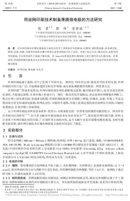
用丝网印刷技术制备薄膜微电极的方法研究张 君1,2 郭 伟3 袁倬斌*1,21(中国科学院研究生院应用化学研究所,北京100049)2(中国科技大学研究生院应用化学研究所,北京100049)3(中国科学院生态环境研究中心,北京100085)摘 要 对丝网印刷术在微电极制备方面的应用作了系统和详尽的描述,对绷网、制阳图底板、涂布感光胶、晒网、显影、坚膜、印刷等印制各步骤中所需注意事项和技巧作了总结。
考察了标记方式、曝光时间、显影时间等的影响,并在优化条件下制成了微电极。
用1mm ol /L 铁氰化钾在微电极上进行循环伏安扫描实验。
结果表明,所制得的微电极条具有良好的电化学性能。
用此方法可大批量制得廉价的适用于电化学研究和应用的微电极条。
关键词 丝网印刷,微电极,电化学 2004-07-04收稿;2005-01-17接受本文系“十五”科技攻关重大项目(No .2001BA210A04-7)、国家自然科学基金(No .2175025)、国家自然科学基金分析化学重点基金(No .20235010)和电分析化学国家重点实验室基金资助项目1 引 言丝网印刷起源于我国,至今已有两千年的历史。
20世纪70年代以来,随着科学技术的发展,丝网印刷的应用日益广泛,并逐渐渗透到分析化学领域,成为制备薄膜微型电极的一种重要方法。
丝网印刷[1]的基本原理是:丝网印版的部分网孔能够透过油墨,漏印制承印物上;而其余部分的网孔堵死,不能透过油墨,在承印物上形成空白。
现代一般用光化学制版法,该法是将丝网绷紧在网框上,然后在网上涂布感光胶,形成感光版膜,再将阳图底板密合在版膜上晒版,经曝光、显影,印版上不需过墨的部分受光形成固化版膜,将网孔封住,印刷时不透墨;印版上需要过墨的部分的网孔不封闭,印刷时油墨透过,在承印物上形成墨迹。
由于丝网印刷技术所需设备简单,投资小,可制备便宜的一次性使用的微型电极的优点。
国内外有许多相关应用研究[2~4],但大多文献对印制电极技术本身涉及很少[5,6],现有的丝网印刷书籍、资料又只着重于丝网印刷在纺织印染、广告制作等方面的应用,迄今文献中未见印制微电极的报道,本研究根据实验结果,就丝网印刷技术在微电极制备方面的应用进行了报道。

酞菁铜缓冲层对有机太阳能电池开路电压的影响
王桂伟;邢英杰
【期刊名称】《红外与毫米波学报》
【年(卷),期】2015(034)004
【摘要】用p型有机半导体材料酞菁铜作为阴极缓冲层制作了器件结构为氧化铟锡/酞菁锌/碳六十/酞菁铜/铝的有机小分子太阳能电池,对器件进行电学测量发现酞菁铜缓冲层的厚度对器件的开路电压有明显影响.基于半导体器件物理分析了光照下测量得到的电流-电压曲线,由拟合结果得到的器件参数表明高理想因子导致了器件开路电压升高,其原因为器件的输运特性不只受酞菁锌与碳六十形成的p-n结影响,还与酞菁铜缓冲层与铝电极形成的肖特基接触有关.研究表明在有机太阳能电池器件中引入一个合适的缓冲层/阴极肖特基结可以提高器件的开路电压.
【总页数】5页(P396-400)
【作者】王桂伟;邢英杰
【作者单位】北京大学纳米器件物理与化学教育部重点实验室,北京100871;北京大学纳米器件物理与化学教育部重点实验室,北京100871
【正文语种】中文
【中图分类】TM914.4;TN36;TN304.5
【相关文献】
1.双层阴极缓冲层有机太阳能电池探析 [J], 吕晶
2.TiO2阴极缓冲层对 Rubrene/C70有机太阳能电池性能的改善 [J], 张利忠;吴明
晓;田金鹏;吴步军;谢伟广;刘彭义
3.退火处理ZnPc(OC8H17OPyCH3I)8阴极缓冲层的倒置有机太阳能电池 [J], 郑爽;张宏梅;王悦;黄维
4.双层阴极缓冲层有机太阳能电池探析 [J], 吕晶;
5.Bphen作为缓冲层对有机太阳能电池的光电性能影响 [J], 黄秋炎;钟建;刘峰;高卓;于军胜;蒋亚东
因版权原因,仅展示原文概要,查看原文内容请购买。
![丝网印刷碳电极预处理方法[发明专利]](https://img.taocdn.com/s1/m/313bdd1d443610661ed9ad51f01dc281e53a561d.png)
[19]中华人民共和国国家知识产权局[12]发明专利申请公布说明书[11]公开号CN 101235502A [43]公开日2008年8月6日[21]申请号200710144111.X [22]申请日2007.12.27[21]申请号200710144111.X[71]申请人福州大学地址350002福建省福州市工业路523号[72]发明人孙建军 韦航 林志彬 陈国南 [74]专利代理机构福州元创专利代理有限公司代理人蔡学俊[51]Int.CI.C23F 1/32 (2006.01)B41J 15/00 (2006.01)权利要求书 1 页 说明书 4 页 附图 2 页[54]发明名称丝网印刷碳电极预处理方法[57]摘要本发明提出了丝网印刷碳电极预处理方法,其特征在于:所述方法为化学处理法以及化学与电化学结合处理法两种方法,化学处理法是将丝网印刷碳电极在高浓度强碱溶液中浸泡一定时间;而化学与电化学结合处理法是将丝网印刷碳电极在高浓度强碱溶液中浸泡后,再将浸泡后的电极在低浓度的碱溶液中恒电位活化一定时间。
相比其他印刷碳电极的预处理方法,本发明所采用预处理方法处理后的电极可逆性和电子转移速率显著增强,电荷传递阻抗大大减小,电极的活性面积增加十几倍;同时对生物小分子(如多巴胺)的响应增大上千倍。
这种预处理方法简单,操作简便,可实现电极批量处理,所用试剂十分廉价易得。
200710144111.X权 利 要 求 书第1/1页1.一种丝网印刷碳电极预处理方法,其特征在于:所述方法为:将丝网印刷碳电极在高浓度强碱溶液中浸泡一定时间;所述高浓度强碱溶液的浓度范围为0.1~10mol/L,丝网印刷碳电极在强碱溶液中的浸泡时间为2~300分钟。
2.一种丝网印刷碳电极预处理方法,其特征在于:所述方法为:将丝网印刷碳电极在高浓度强碱溶液中浸泡后,再将浸泡后的电极在低浓度的碱溶液中恒电位活化一定时间,所述高浓度强碱溶液的浓度范围为0.1~10mol/L,丝网印刷碳电极在强碱溶液中的浸泡时间为2~300分钟;低浓度碱溶液的浓度范围为0.01~1mol/L,恒电位所施加的阳极电位范围为+0.6~+2.0V,丝网印刷碳电极在低浓度碱溶液中恒电位活化时间为5~600秒。

丝网印刷法制备柔性染料敏化太阳能电池碳对电极李璞;胡志强;苏岩;巩翠翠【摘要】以廉价的炭黑掺杂石墨粉,氯化聚乙酸乙烯酯为胶黏剂制成导电浆料,在柔性基底上用丝网印刷技术制备薄膜,低温热处理后即得碳对电极.通过黏度计研究了料浆的流变性能,通过四探针测试仪、扫描电镜,太阳电池测试仪,分别测试了碳对电极的方块电阻、表面形貌及其光电性能.实验表明,以叔丁醇作为分散剂,导电浆料与石墨的质量比为2:1时,料浆的流变性能最佳,以此料浆制备的碳对电极具有较好的电性能,通过对比发现在料浆中加入石墨一定程度上提高了碳电极的性能.【期刊名称】《大连工业大学学报》【年(卷),期】2009(028)004【总页数】3页(P274-276)【关键词】太阳能电池;碳对电极;丝网印刷;石墨【作者】李璞;胡志强;苏岩;巩翠翠【作者单位】大连工业大学,化工与材料学院,辽宁,大连,116034;大连工业大学,化工与材料学院,辽宁,大连,116034;大连工业大学,化工与材料学院,辽宁,大连,116034;大连工业大学,化工与材料学院,辽宁,大连,116034【正文语种】中文【中图分类】TB6110 引言当前,染料敏化太阳能电池的研究主要集中在染料合成、电子输运过程理论、固态(或准固态)电解液等方面,针对对电极的专项研究较少,对电极作为纳晶敏化太阳能电池的重要组成部分,通常由载铂催化剂的导电玻璃构成。
铂使对电极/电解液界面上的电荷迁移快速高效进行,减小了与TiO2导带中的电子发生复合的几率,抑制了暗电流,提高了电池的开路电压。
但是由于铂等贵金属催化剂的使用成本高,因此人们尝试采用其他材料替代铂作电池的对电极材料。
碳材料由于具有较好的电子传导率、性能稳定、高催化活性、低成本等特点[1-2],成为催化剂研究的一个热点。
Imoto等[3]用活性炭在FTO玻璃基底上制备的碳对电极,电池性能为:Jsc=7.93 mA/cm2,Voc=808 mV,ff=0.607,η=3.89%,性能低于磁控溅射制备的铂对电极(η=4.3%)。
Biosensors and Bioelectronics 24(2009)2885–2891Contents lists available at ScienceDirectBiosensors andBioelectronicsj o u r n a l h o m e p a g e :w w w.e l s e v i e r.c o m /l o c a t e /b i osImpedimetric genosensors employing COOH-modified carbon nanotube screen-printed electrodesA.Bonanni,M.J.Esplandiu,M.del Valle ∗Sensors and Biosensors Group,Department of Chemistry,Universitat Autònoma de Barcelona,Edifici Cn,08193Bellaterra,Barcelona,Spaina r t i c l e i n f o Article history:Received 29October 2008Received in revised form 8January 2009Accepted 20February 2009Available online 6March 2009Keywords:GenosensorElectrochemical impedance spectroscopy GMOGold nanoparticles Carbon nanotubesa b s t r a c tScreen-printed electrodes modified with carboxyl functionalised multi-walled carbon nanotubes were used as platforms for impedimetric genosensing of oligonucleotide sequences specific for transgenic insect resistant Bt maize.After covalent immobilization of aminated DNA probe using carbodiimide chemistry,the impedance measurement was performed in a solution containing the redox marker ferro-cyanide/ferricyanide.A complementary oligomer (target)was then added,its hybridization was promoted and the measurement performed as before.The change of interfacial charge transfer resistance between the solution and the electrode surface,experimented by the redox marker at the applied potential,was recorded to confirm the hybrid formation.Non-complementary DNA sequences containing a different number of base mismatches were also employed in the experiments in order to test specificity.A sig-nal amplification protocol was then performed,using a biotinylated complementary target to capture streptavidin modified gold nanoparticles,thus increasing the final impedimetric signal (LOD improved from 72to 22fmol,maintaining a good reproducibility,in fact RSD <12.8%in all examined cases).In order to visualize the presence and distribution of gold nanoparticles,a silver enhancement treatment was applied to electrodes already modified with DNA–nanoparticles conjugate,allowing direct observation by scanning electron microscopy.©2009Elsevier B.V.All rights reserved.1.IntroductionElectrochemical impedance spectroscopy (EIS)is a rapidly developing technique for the transduction of biosensing events at the surface of an electrode (Berggren et al.,1999).Due to its effec-tiveness to directly probe the interfacial properties (capacitance,electron transfer resistance)of modified electrodes (Gabrielli,1990;Patolsky et al.,1998),EIS is becoming an attractive electrochemi-cal tool for numerous applications such as immuno (Willner and Willner,1999;Farace et al.,2002;Huang et al.,2006)and genosens-ing (Tlili et al.,2005;Peng et al.,2007;Xu et al.,2004),enzyme activity determination (Kharitonov et al.,2000;Saum et al.,1998),studies of corrosion (Mansfeld et al.,1997;Rout,2007)and sur-face phenomena (Millan et al.,1994).In the more recent years,EIS (MacDonald,1987;Bard and Faulkner,2000)was widely used for the detection of DNA hybridization,occurring at a sensor surface (Breggen et al.,2000;Katz and Willner,2003;Lisdat and Shafer,2008).Carbon nanotubes (CNTs)have attracted increasing interest of many researchers due to their remarkable tensile strength,high resistance,flexibility and other unique structural,mechani-∗Corresponding author.Tel.:+34935811017;fax:+34935812379.E-mail address:manel.delvalle@uab.cat (M.del Valle).cal,electrical and physicochemical properties (Khabashesku et al.,2005;Hu et al.,2005;Treachy et al.,1996)(high specific surface area,electrocatalysis effects reflected on increased signal currents and decreased overpotentials,versatility for biofunctionalization).Besides these brilliant properties,also the possibility to function-alize them directly with different kinds of biomolecules (Daniel et al.,2007;Vairavapandian et al.,2008)and their biocompati-bility make CNTs extremely attractive for electrochemical sensing.Numerous platforms employing different kinds of CNTs alone or combined with gold nanoparticles were recently fabricated and characterized (Gong et al.,2008;Vairavapandian et al.,2008;Yun et al.,2008).Electrodes modified with CNTs have been employed for the improved detection of either inorganic or biological molecules (Strano,2004;Wang et al.,2004a,b ).CNTs have been recently used as transducers for enhanced electrical detection of DNA hybridiza-tion (Wang et al.,2003,2004a,b ).CNTs were also used for biosensing in combination with nanoparticles in order to improve the final response (Wang et al.,2003;Male et al.,2004).DNA biosensor technologies are rapidly developing as an alter-native to the classical genic assays,due to several features such as low cost,rapid analysis,simplicity and possibility of multiplexing and miniaturization (Cattrall,1997).Genosensors (or DNA biosen-sors)are devices that combine a transducer with a single-stranded DNA (ssDNA)called DNA probe,acting as a recognition element.These devices make use of hybridization event to detect a target0956-5663/$–see front matter ©2009Elsevier B.V.All rights reserved.doi:10.1016/j.bios.2009.02.0232886 A.Bonanni et al./Biosensors and Bioelectronics24(2009)2885–2891DNA sequence(Yang et al.,1997).The determination of nucleic acid fragments from humans,animals,plants,bacteria and viruses is the departure point to solve different problems:investigation about food and water contamination caused by micro organisms,detec-tion of genetic disorders,identification of species,tissue matching, forensic applications,etc.(Drummond et al.,2003;Righetti and Gelfi,1997).One of the most recent and requested DNA-sensor applications is the detection of genetically modified organisms(GMOs)in foods.A GMO is referred to a living organism whose genome has been modified by the introduction of an exogenous gene able to express an additional protein that confers new characteristics.An intense debate is in progress,which is the ethical use of transgenic crops to improve agricultural productivity in food production.The main transgenic crops are soybean,maize and cotton,and the major incorporated traits include herbicide tolerance and resistance to virus,antibiotics and insects(Mariotti et al.,2002;Minunni et al., 2001).The potentially increasing number of GMO-derived com-mercialized products,present at the moment in the food market has led many countries to require regulation and labeling of grains and foodstuff containing GMOs.For this reason,there is a strong interest in the development of reliable and rapid analytical meth-ods for GMO detection and quantification(Erickson,2000;Hubner et al.,1999).At present,analytical methods for GMOs can detect both the new protein expressed by the genetically modified DNA sequence or the sequence itself.The detection of the former is generally based on enzymatic immunoassay analysis(Lipp et al., 2000;Stave,2002).However,since food processing often leads to protein denaturation,the analysis of DNA,which is much highly stable than proteins,is preferred for screening of both raw ingre-dients and processed products.DNA recognition is based on the hybridization of target DNA sequence with GMO-specific probes that are immobilized on the surface of the sensor(Kalogianni et al.,2006).At the moment,various transduction principles have been reported,such as protocols based on the use of quartz crystal microbalance(Minunni et al.,2001;Mannelli et al.,2003),surface plasmon resonance(Giakoumaki et al.,2003;Feriotto et al.,2002) or electrochemical transduction based on the use of electroactive compounds(Minunni et al.,2001).In this work we report the impedimetric detection of transgenic insect resistant Bt maize DNA,by the use of carbon nanotubes as sensing platform.Carbon nanotubes used were modified with carboxylic groups,which allowed the covalent immobilization of the oligonucleotide sequence under study.The impedimetric tech-nique,employed for thefirst time with this kind of electrodes, allowed either the detection of complementary DNA sequences or their quantification.Moreover,with the use of a signal ampli-fication protocol based on the use of streptavidin-modified gold nanoparticles(strept-AuNPs),the detection of different number of mismatches was attainable.2.Experimental2.1.MaterialsPotassium ferricyanide K3[Fe(CN)6],potassium ferrocyanide K4[Fe(CN)6],streptavidin-gold nanoparticles(Ref.S9059),N-(3-dimethylaminopropyl)-N -ethylcarbodiimide hydrochloride(EDC), sodium dodecylsulphate(SDS),iron(III)nitrate nonahydrate, were purchased from Sigma(St.Louis,MI).N-Hydroxysulpho-succinimide sodium salt(sulpho-NHS),poly(ethylene glycol)(PEG) was purchased from Fluka(Buchs,Switzerland).Hydroxylamine hydrochloride was purchased from Merck(Darmstadt,Germany).LI Silver Enhancement Kit was obtained from Nanoprobes(Yaphank, NY).Other reagents were commercially available and were all of analytical reagent grade.All solutions were made up using dou-bly distilled water.The following buffer was employed:0.1M PBS (0.1M NaCl,0.01M sodium phosphate buffer,pH7.0).The different oligonucleotides used in the study were pre-pared by TIB-MOLBIOL(Berlin,Germany).Their sequences and modifications are the following:probe-NH2:5 NH2-CCGCTGTATC ACAAGGGCTG GTAC3 ;complementary target:5 GTACCAGCCC TTGT-GATACA GCGG3 ;target-bio:5 BIO-GTACCAGCCC TTGTGATACA GCGG 3 ;target with one mismatch:5 GTACCAGCCC TTGT C ATACA GCGG3 ; target with two mismatches:5 GTACCAG G CC TTGTGATAC C GCGG3 ; target with three mismatches:5 GTACC T GCCC TTGTG C TACA G A GG 3 ;non-complementary target:5 AAAAAAAAAA AAAAAAAAAA AAAA 3 .Stock solutions of the oligonucleotides were diluted with ster-ilized and deionised water,separated in fractions and stored at a temperature of−20◦C.When required,a single fraction was defrosted and used.Screen-printed electrodes(SPEs)modified with carboxyl func-tionalised multi-walled carbon nanotubes(MWCNT-COOH,Ref. 110-CNT)were obtained from Drop Sens(Oviedo,Spain).2.2.ApparatusAC impedance measurements were performed with an IM6e Impedance Measurement Unit(BAS-Zahner,Germany).Thales soft-ware was used for the acquisition of the data and the control of the experiments.A three electrode cell was used to perform impedance measurements;working electrode(4mm diameter)was made of –COOH modified carbon nanotubes,counter electrode was made of carbon,whereas reference electrode and electric contacts were made of silver.A scanning electron microscope(SEM,Hitachi S-570,Tokyo, Japan)was used to visualize strept-AuNPs on electrode surface. 2.3.Biosensing protocol2.3.1.Electrochemical pre-treatmentThe various SPE electrodes were electrochemically pre-treated (Musameh et al.,2005;McCreery,2008)prior to voltammetric mea-surement(see‘Supporting information’section for experimental details).2.3.2.Immobilization of DNA probeModification of the MWCNT-COOH modified screen-printed electrodes was performed in different steps:(i)15L of0.05M EDC and0.03M sulpho-NHS in PBS buffer,pH7,were deposited onto the electrode surface for15min in order to activate carboxylic acid groups;(ii)the electrodes were then thoroughly rinsed with PBS;(iii)15L of3pmol of probe-NH2solution in PBS,pH7(see ‘Supporting information’section for optimization of probe con-centration),were then deposited onto the electrode surface and let stood overnight at room temperature under a wet environ-ment;(iv)this was followed by a washing step with0.05%SDS and0.04M hydroxylamine hydrochloride to remove non-specific adsorbed probe and deactivate any remaining carboxylic group (Shervedani and Bagherzadeh,2008).Negative controls were per-formed bypassing thefirst activation step.2.3.3.Hybridization with DNA targetBefore hybridization,a blocking step was performed in order to avoid non-specific adsorption of target oligonucleotide.The elec-trode surface was treated with a0.04M solution of PEG in PBS,pH 7for15min and then rinsed with PBS.Hybridization was performed incubating the NH2-probe mod-ified electrodes with15L of2pmol of target oligonucleotide solution in PBS buffer(concentration optimized in Section3.1.2). The hybridization was achieved at room temperature,for30min.A.Bonanni et al./Biosensors and Bioelectronics 24(2009)2885–28912887Fig.1.Scheme of experimental procedure.This was followed by a gentle washing step in PBS buffer.Negative controls were performed using either a non-complementary target or the buffer solution alone during hybridization step.2.3.4.Signal amplification employing strept-AuNPsSPE electrodes modified with target-bio were incubated with a solution of strept-AuNPs (1/100dilution from stock solution)in PBS buffer,pH 7,for 20min at room temperature.This was followed by a gentle washing step in PBS.Negative controls were performed using the non-biotinylated complementary target.2.3.5.Silver enhancement of strept-AuNPs15L of a solution obtained by the combination of equal vol-umes of enhancer and initiator were deposited onto the electrode surface and left 5min for the reaction.The electrodes werethenFig.2.Nyquist diagrams for EIS measurements of:(᭹,filled circles)bare SPE;( ,empty circles)probe-NH 2modified electrode;( ,filled triangles)biotinylated-hybrid modified electrode ( ,empty triangles)biotinylated-hybrid modified electrode +strept-AuNPs;( ,filled squares)biotinylated-hybrid modified elec-trode +silver enhanced strept-AuNPs.All measurements were performed in 0.1PBS buffer solution containing 10mM K 3[Fe(CN)6]/K 4[Fe(CN)6].On the left corner:Ran-dles equivalent circuit used for data fitting in EIS measurements.washed with deionised water to stop the reaction.The silver enhancing solution was freshly prepared before each use.Negative controls were performed using the non-biotinylated complemen-tary target.The whole experimental procedure is represented in Fig.1.2.3.6.Impedimetric detectionImpedance measurements were recorded between 50kHz and 0.05Hz,at sinusoidal voltage perturbation of 10mV amplitude and a sampling rate of 10points per decade above 66Hz and 5points per decade at the lower range.The experiments were carried out under open circuit potential conditions in an unstirred solution of 0.1M PBS buffer solution containing 0.01M K 3[Fe(CN)6]/K 4[Fe(CN)6](1:1)mixture,used as a redox marker.The obtained spectra were represented as Nyquist plots (−Z i vs.Z r )in the complex plane.A Randles equivalent circuit was used to fit the obtained impedance spectra.The chi-square goodness of fit was calculated for each fitting by the FRA software employed (Eco Chemie,Utrecht,the Netherlands).3.Results and discussion3.1.Impedimetric detection of DNA hybridization and signal amplificationFig.2shows the different Nyquist plots obtained in a whole experiment of DNA biosensing,including signal amplification step and silver enhancement treatment.In this case,the bare electrode was successively modified with:(1)probe-NH 2;(2)target-bio;(3)strept-AuNPs;(4)silver enhancement treatment.After each step,an EIS measurement was performed.From the obtained impedimet-ric spectra,a Randles equivalent circuit,represented in the same figure,was proposed to fit the experimental data.In the circuit,the parameter R 1represents the resistance of the solution;R 2(also called R ct )corresponds to resistance to the charge transfer between the solution and the electrode surface;W is the Warburg impedance and represents the contribution of the diffu-sion;CPE is associated to the capacitance of the double layer (due to the interface between the electrode and the electrolytic solution).The use of a constant phase element (CPE)instead of a capacitor is2888 A.Bonanni et al./Biosensors and Bioelectronics 24(2009)2885–2891required for a better fitting of the experimental data and it is gener-ally due to the electrode surface non-idealities (MacDonald,1987;Gabrielli,1990).In this study,we focused on the charge transfer resistance (R ct )between the solution and the electrode surface.The charge transfer process is caused by the presence of the redox marker—the ferro-cyanide/ferricyanide couple in the bulk solution.Any modification of the electrode surface strongly influences its electrochemistry,thus leading to a change in the R ct value (R ct corresponds to the diameter of the spectrum semicircle).For this reason,it is possible to monitor each step of the biosensing (i.e.probe immobilization,hybridization with target,strept-AuNPs and silver enhancement treatment),just following the variation of R ct .Besides,the change of time constant of the semicircle was also monitored but it was not significant.The related difference of frequencies at the apex of the semicircle was within ±one experimental step of scanned frequency.For all the fittings of equivalent circuits,the chi-square goodness-of-fit test calculated by the FRA software used was thoroughly checked to verify performed calculations.In all cases,calculated values for each circuit remained in the range of 0.008–0.03much lower than the tabulated value for 50degrees of freedom (67.505at 95%confidence level),thus demonstrating the high significance of the final fittings.As it can be observed in Fig.2,the R ct value—diameter of the semicircle,increased after each performed step.This can be attributable to the augmented difficulty of the redox reaction of [Fe(CN)6]3−/4−to take place at the CNT surface,due to its alter-ation by interaction with DNA.Two different factors should be taken into account to properly explain that:electrostatic repul-sion and sterical hindrance.The former is more significant in the first and second step:when DNA probe (probe-NH 2)is immobilized onto the electrode surface,a first layer is formed,where negatively charged phosphate groups of DNA skeleton are responsible of the electrical repulsion towards the negatively charged redox marker,thus inhibiting the interfacial electron transfer process and increas-ing the R ct value.The addition of a second DNA strand to form DNA hybrid results in further increment of resistance value due to the augmented quantity of negative charges and to the hindrance caused by the formation of a double layer.Hence,DNA hybridization can be proved by this further increment of R ct .After the addition of strept-AuNPs we could observe an extra increment of charge transfer resistance because of the increased space resistance due to the formed conjugates.Moreover at working pH 7,streptavidinFig. 3.Histograms to compare experiments with different oligonucleotide sequences and two negative controls. ratio = s / p ; s =R ct(sample)−R ct(blank); p =R ct(probe)−R ct(blank).Error bars correspond to triplicate experiments.is slightly negatively charged (Sivasankar et al.,1998)(p I is around pH 5)and this fact also contributed to enhance the resistance as a consequence of the electrostatic repulsion with redox marker.In order to observe the presence and distribution of strept-AuNPs,a silver enhancement treatment was applied to electrodes already modified with DNA–strept-AuNPs conjugates.EIS measure-ment was also performed after this treatment and,as shown in the figure,a further increment of R ct value was observed because of the considerable sterical hindrance generated by silver deposition on gold.The first two steps of the biosensing (without performing any signal amplification)provided satisfactory results in the detection of DNA hybridization and the discrimination of a com-plete complementary target,a three mismatched sequence and a non-complementary target.The further signal amplification was performed either to increase the sensitivity of the method or to discriminate between one and two mismatches,being the impedi-metric response without signal amplification indistinguishable from the complementary target one.3.1.1.Discrimination among complementary,non-complementary and mismatched target sequencesFig.3shows results obtained in the hybridization experiments performed to discriminate impedimetric signals among comple-mentary,non-complementary and targets with different number of mismatched bases (randomly placed).As already mentioned,in these experiments no signal amplification was performed.Results are expressed as the relative R ct variation between the values obtained in the different experiments (i.e.DNA adsorption or hybridization)and R ct value due to the bare electrode.This rel-ative variation is represented as a ratio of delta increments (see ratio = s / p ,caption of Fig.3).The elaboration required for the comparison of data from different electrodes has been already used and extensively explained in previous work (Bonanni et al.,2006).Briefly, s / p value should be >1for the hybridization experi-ments and close to 1for negative controls with non-complementary targets (that means s = p ,i.e.no variation of R ct value after hybridization).In the histogram,the first bar corresponds to R ct variation of a hybridization experiment with a complementary target;the sec-ond bar corresponds to the experiment with a one-mismatched sequence (targ1mis);the third bar is due to an experiment with a two-mismatched sequence (targ2mis);the fourth bar corresponds to the experiment with a three-mismatched sequence (targ3mis);the fifth and sixth bars represent results obtained in negative con-trols,where a non-complementary target or the buffer solution alone were used in hybridization step.As it can be observed,the highest ratio is obtained when a complementary target is used,as expected.When a non-complementary target is used,the signal variation during the hybridization step can be considered negligi-ble,as shown in the fifth bar,where delta ratio approaches 1;this means double stranded DNA was not formed.The experiment with a three mismatched target provided a ratio value considerably lower than the one obtained with a com-plete complementary target.This is due to the less hybridization efficiency,caused by the presence of three mismatches in the sequence of bases.However,this value is also significantly differ-ent from the one provided by the non-complementary target,thus indicating that certain affinity interaction took place despite the presence of three mismatches.As shown in the figure,for both experiments with one-and two-mismatched targets (second and third column of the histogram),their signals were very similar and also close to the one coming from the experiments with a completely complementary target.How-ever,their signal was significantly different from the one provided by the negative control.Moreover,results obtained with one andA.Bonanni et al./Biosensors and Bioelectronics 24(2009)2885–28912889two mismatched targets presented a worse reproducibility (RSD%around 13%)than the ones obtained in the other experiments (RSD%less than 10%).These observations were confirmed by a one-way analysis of variance (ANOVA)test,followed by Tukey’s Honestly Signif-icance Difference (HSD)post hoc test,performed to compare results obtained in hybridization experiment among them and with negative controls.With ANOVA test it was demonstrated that there was a statistical significant difference among the different experiments realized (F calc =39.4,much larger than F tab =3.11at 95%confidence level).The further Tukey’s HSD test permitted the differentiation among two situations,correspond-ing to negative controls and to the four different experiments.The post hoc test demonstrated that negative controls (exper-iments 5and 6)were not statistically different between them (Q calc =0.095<Q tab (95%)=4.75).In the same way,a statistically significant difference was demonstrated among the experiments with completely complementary target and three mismatched target between them (Q calc =9.61<Q tab (95%)=4.75)and with neg-ative controls (Q calc >4.89for all examined cases,larger than Q tab (95%)=4.75).Finally,the test also demonstrated that experi-ments with one and two mismatched targets were not statistically different neither between them (Q calc =0.058<Q tab (95%)=4.75),nor from the experiments with completely complementary tar-get (Q calc <3.144for both cases,smaller than Q tab (95%)=4.75).These statistical conclusions confirm the observations suggested for experiments without signal amplification.3.1.2.Impedimetric response towards DNA target concentrationIn order to quantify the degree of signal amplification obtained with the use of strept-AuNPs,the impedimetric response was mea-sured using a fixed concentration of DNA probe and different amount of DNA biotinylated target.In Fig.4the results obtained with these experiments are shown.As we can see the increment of target concentration lead to higher analytical signal due to the increment of R ct ,thus achieving a dynamic range between 0.01and 2pmol (empty squares).After this point a plateau was reached and a further increment of target amount did not correspond to any enhancement of the signal.If we compare these results with those obtained without strept-AuNPs amplification (filled circles),we can observe thatanFig.4.Calibration curves obtained with SPEs modified with (a)different amounts of DNA biotinylated hybrid +strept-AuNPs ratio (empty squares);(b)different amounts of non-biotinylated DNA (filled circles).Volume used of all DNA sequences was 15L.( ratio = g / p ; s =R ct(AuNPs)−R ct(blank); p =R ct(probe)−R ct(blank)).Error bars correspond to triplicateexperiments.petitive assay performed when fixing the concentration of biotinylated DNA target at 2pmol value and increasing the concentration of respectively:(a)unla-belled complementary target;(b)unlabelled one-mismatched target;(c)unlabelled two-mismatched target.Error bars correspond to triplicate experiments.equivalent reading (expressed as ratio ),was obtained when a higher amount of DNA target was employed.In fact,as shown in Fig.3(Experiment A), ratio value of about 2.8corresponded to a DNA target amount of 2pmol in experiments without signal ampli-fication,whilst the same value it was due to a target concentration around 0.05pmol in experiments with strept-AuNPs.This means we could obtain the same signal with a DNA concentration 40times lower.Results with smaller amount of DNA target were not reported due to the lower reproducibility.petitive binding assay and detection of mismatchesThe aim of this experiment was the quantification of non-labelled DNA target,as well as the detection of DNA sequences with one or two mismatches.In both cases,the quantification of unknown amount of unlabelled DNA in the presence of a fixed amount of competing biotinylated ssDNA competitor (Bonanni et al.,2008)was performed.The results obtained in these experiments are shown in Fig.5.As shown in the figure,curve (a),the signal magnitude at low concentration of unlabelled DNA target (left part of the figure)was comparable to the one obtained in the study of the impedimet-ric response toward DNA target concentration (Fig.4),in which only biotinylated DNA target was present.Increasing the concentra-tion of unlabelled ssDNA in the hybridization step,the competition between the two targets led to a decrement of the signal.In fact,when decreasing the amount of biotinylated target binding to the probe modified electrode,the effectiveness of signal amplification due to strept-AuNPs addition is reduced as well.In the final part of the experiment (right part of the figure),the further increment of unlabelled DNA target concentration caused an additional decrease and stabilization of the signal.This experiment was performed in order to apply the method to practical detection of DNA from real samples,which preferably should be unlabelled.In fact,as deducted from the figure,the protocol allowed the detection of sample DNA amount around 1.6pmol (calculated as EC 50in the graph).In part (b)and (c)the detection of respectively one-mismatched and two-mismatched sequences was performed.As expected,the decrement of the signal due to the presence of the competitor is lower than in the case of a completely complementary target,due to the reduced efficiency of hybridization caused by the pres-ence of mismatches.Obviously,in the case of two-mismatched sequence (curve (c)),the variation of impedimetric signal is even lower than in the case of one-mismatched sequence (curve (b)),being the hybridization with a two-mismatched target less effec-tive than hybridization with one mismatch.In the latter cases,the。
丝网印刷碳电极预处理方法研究及其检测应用郭佩佩; 欧阳文鹏; 黄家怿【期刊名称】《《广州化工》》【年(卷),期】2019(047)015【总页数】4页(P34-37)【关键词】丝网印刷碳电极; 电化学预处理方法; 重金属检测; 方波溶出伏安法; 应用广泛【作者】郭佩佩; 欧阳文鹏; 黄家怿【作者单位】广州市健坤网络科技发展有限公司广东广州 510630; 广东省现代农业装备研究所广东广州 510630【正文语种】中文【中图分类】O657.1近年来,因电化学分析方法具有灵敏度高、反应快速、操作简单、检测时间短等特点,而在食品安全、医学诊断、环境监测等方面应用广泛[1]。
但其使用的传统电极如玻碳等碳系列电极,和金、铂等金属电极,价格较贵,使用成本过高,样品需要量大,且每次使用前均需对电极进行复杂预处理,且多次使用会导致交叉污染、重现性和稳定性下降等问题[2],因此迫切需要一种制作工艺简单、能批量化生产、稳定性好、化学性能相同、成本低廉且便于携带的传感器出现[3-5]。
丝网印刷碳电极(Screen-printed carbon electrode,SPCE)是采用丝网印刷技术制备的大小形状设计灵活、易微型化、易集成化、试剂消耗量小、成本更低廉、抛弃式一次性使用、可大批量生产的电极[6-7],有助于避免上述电极在污染物检测中的不利问题[5,8]。
但因丝网印刷电极制备过程中,印刷使用的碳浆由石墨粉、有机粘合剂、有机溶剂及添加剂组成,这些有机类的绝缘物质对电极性能有很大影响,如灵敏度、导电性和电子转移速率会下降等问题,所以需要在SPCE修饰前或检测前,对其进行预处理活化,以除去表面有机物、聚合物和其他杂质,从而使SPCE碳活性点暴露在外,增强电极导电性和功能性[9]。
目前文献报道的有几种预处理方法,包括机械抛光、激光处理、酸碱洗涤和电化学清洗等四种方法[9-10]。
前面两种方法仪器昂贵、对操作者专业知识要求高、且可能会破坏电极;酸碱洗涤可能会造成电极表面化学性能改变;而电化学清洗方法操作简便,通常采用循环伏安法(CV)或电流-曲线法(i-t法)对电极进行阳极化处理,可有效增强电极可逆性和电子转移速率,增加电极活性位点面积。
丝网印刷选择离子电极测定药物试剂中的氢溴酸西酞普兰Tamer Awad Ali;Gehad G.Mohamed;A.M.Al-Sabagh;M.A.Migahed【期刊名称】《分析化学》【年(卷),期】2014(42)4【摘要】以四硼酸钾(KTpClPB)离子载体(电极V)和西酞普兰磷钨酸(cp-pt)离子对混合物(电极X)作为丝网印刷电极的电活性物质、磷酸三甲苯酯(TCP)作为溶剂中介,制备并表征了一种新型丝网印刷离子选择电极.利用此电极测定药剂中的西酞普兰,在4.90×10⁻⁷~1.0×10⁻²(电极V)和1.0×10⁻⁶~1.0×10⁻² mol/L(电极X)浓度范围内呈一近似-Nernstain响应,斜率分别为60.47±0.80和59.93±1.45mV/decade,检出限分别为0.49和1.0 μmol/L.电极具有响应快、重复性好、稳定性高(电极V:5个月,电极X,4个月)、宽pH值适应范围(电极V:2 ~9,电极X,2~8)以及良好的选择性等特点,可应用于测定尿液和血清中的西酞普兰.【总页数】8页(P565-572)【作者】Tamer Awad Ali;Gehad G.Mohamed;A.M.Al-Sabagh;M.A.Migahed 【作者单位】Egyptian Petroleum Research Institute(EPRI), Cairo 11727, Egypt;Chemistry Department, Faculty of Science, Cairo University, Giza 12613, Egypt;Egyptian Petroleum Research Institute(EPRI), Cairo 11727, Egypt;Egyptian Petroleum Research Institute(EPRI), Cairo 11727, Egypt 【正文语种】中文【相关文献】1.氟离子选择电极法测定药物中的氟喹诺酮 [J], 黄超伦;栗瑞芬;修荣2.离子选择电极法和新氟试剂光度法测定空气中HF的比较 [J], 吴晋霞;李杰;周益民;王绍俊3.离子选择电极法测定有机分析试剂的纯度 [J], 曲祥金;周杰4.钛铁试剂掩蔽离子选择电极测定铝中微量氟 [J], 吴克义5.Nafion复合铋膜修饰丝网印刷电极测定痕量镉离子 [J], 唐立超;唐美华;石成成;蔡清;张东明;张之翼;王济奎;陈国松因版权原因,仅展示原文概要,查看原文内容请购买。
简介
可弃式丝网印刷钴-酞化菁/碳(型号:410)理想用于在地检测电位下对过氧化氢的测定。
建议这些电极用于基于氧化酶的酶生物传感器的研究中,以及微量体积的分散式分析化验。
410型丝网印刷钴-酞化菁/碳电极最小包装75只/每盒,应存放于室温干燥的封闭环境中。
可以选配以下两种特制的连接器/转接头作为丝网印刷电极与任何恒电位仪等电化学仪器之间的连接界
面。
DSC 型转接头CAC 型导线接头
钴-酞化菁/碳丝网印刷电极也可以批量使用过氧化氢的计时电流检测,只需使用40μL 的一滴样品。
z
陶瓷基片:33×10×0.5mm z
电接触点:银z
工作电极:钴-酞化菁/碳(4mm 直径)z
对电极:碳z 参比电极:Ag
www.eDAQ
Email:info@.c n
Tel:+86-21-52751994文件编号:SPCE-410易达科技术有限公司Fax:+86-21-52753613Copyright @eDAQ 2010
过氧化氢在丝网印刷钴-酞化菁/
碳上的电流检测
使用我们的方便的流通池在流动注射分析系统中过氧化氢的电流型检测。
在410型电极上没有积垢和记忆效应的情况下,增加和减少H 2O 2浓度时的电流响应。
E det +0.4V ,流速2.2ml/min ,液流载体为pH7.2的0.1M 磷酸缓冲溶
液。
校准曲线:过氧化氢在pH7.2的0.1M
磷酸缓冲溶液中,浓度从1×10⁻⁶M 到
2.5×10⁻⁴M 在FIA 系统中使用我们的
钴-酞化菁/碳丝网印刷电极
E det +0.4V ,流速2.2ml/min
在左图的分析中,每次测试使用不同的电极。
图中显示在1×10⁻⁶M至1×10⁻⁴M之间不同浓度的过氧化氢分析。
电位程序:0.0V(20s)和+0.4V(180s).
用不同的DRP-410电极检测H2O2,总是获
得低于5%的标准偏差。