华硕主板F1A75-M用户手册
- 格式:pdf
- 大小:3.86 MB
- 文档页数:73
![[VIP专享]华硕笔记本BIOS设置详图](https://uimg.taocdn.com/5e2e649a0740be1e650e9ac2.webp)
华硕笔记本BIOS设置详图首先开机后等系统运行,直到ASUS的标志出现时按F2进入BIOS设置(注意:有的时候按一次F2未必能进入BIOS 设置,所以我们要多按几次)。
进入BIOS界面时我们会看到它划分为三各部分:主菜单、子菜单和操作讲解部分。
1.首先,我们了解一下基本的操作方法:2.←→Select Screen 选择主菜单(翻屏);3.↑↓ Select Ttem 选择子菜单;4.Enter Go To Sub Screen 选择项目;5.F1 General Help 普通帮助;6.F9 Load Defaults 载入出厂设置;7.F10 Save and Exit 保存后退出BIOS;8.ESC Exit 后退2.其次,我们了解一下主菜单从左到右依次是:Main(基本设定)、Advanced(高级设定)、Security(安全性能选项)、Power (电源管理设定)、Boot(启动设备设置)、Exit(退出Bios程序设置)。
基本设定菜单BIOS版本号OK,现在深入讲解这六大部分的设置。
第一部分:基本设定这个菜单可对基本的系统配置进行设定,如时间,日期等。
也是本本的系统概况(Syetem Overview),画线的部分分别是系统BIOS版本号、显示器BIOS版本号;接下来是CPU信息、核心速度;再下面是内存信息。
用圆圈的部分是电脑的时间和日期,可以设置本本的时间和日期。
设置本本的时间和日期第二部分:高级设定接下来,进入BIOS的高级设定,在设定之前要提醒大家一句:新手一定要小心的设置,因为其直接关系系统的稳定和硬件的安全,千万不可以盲目乱设。
从上到下分别是:系统基本硬件设置、Easy-Flash功能选项、内置指针设备设定、数码锁定、声音选项、扬声器音量选项。
1.系统基本硬件设置:又分为两个子菜单,是从主IDE 装置,他们分别管理例电脑里面各个IDE驱动装置的,如硬盘,光驱等等,这些一般不用用户自己去设置,一般用默认的就可以~2.Easy-Flash功能选项:是支持Easy-Flash功能的主板才有的选项,可以在开机自检时按F4或通过BIOS"advanced"菜单中的"Start Easy Flash"选项开启此功能~3.内置指针设备设定:是开启或禁用触摸板的选项,"Disabled"的是禁用,"Enabled"是启用。

Turning your device offPutting on sleep modeTo put your device on sleep mode:Press the Power button once.Forcing your device to shut downTo force shutdown your device:•If your device is unresponsive, press and hold the power button for at least eight (8) seconds.Shutting down your deviceTo shut down your device:1. Launch the Charm bar and tap .2. Tap > Shut down to turn off your device.ASUS Tablet ManualASUS Tablet ManualDeclarations and Safety Statements Federal Communications Commission Statement This device complies with part 15 of the FCC Rules. Operation is subject to the following two conditions: (1) This device may not cause harmful interference, and (2) this device must accept any interference received, including interference that may cause undesired operation.This device has been tested and found to comply with the limits for a Class B digital device, pursuant to Part 15 of the FCC Rules. These limits are designed to provide reasonable protection against harmful interference in a residential installation. This equipment generates, uses and can radiated radio frequency energy and, if not installed and used in accordance with the instructions, may cause harmful interference to radio communications. However, there is no guarantee that interference will not occur in a particular installation If this equipment does cause harmful interference to radio or television reception, which can be determined by turning the equipment off and on, the user is encouraged to try to correct the interference by one or more of the following measures:Reorient or relocate the receiving antenna.Increase the separation between the equipment and receiver.Connect the equipment into an outlet on a circuit different from that to which the receiver is connected.Consult the dealer or an experienced radio/TV technician for help.Changes or modifications not expressly approved by the party responsible for compliance could void the user‘s authority to operate the equipment.The antenna(s) used for this transmitter must not be co-located or operating in conjunction with any other antenna or transmitter.RF Exposure Information (SAR)This device meets the government’s requirements for exposure to radio waves. This device is designed and manufactured not to exceed the emission limits for exposure to radio frequency (RF) energy set by the Federal Communications Commission of the U.S. Government.The exposure standard employs a unit of measurement known as the Specific Absorption Rate, or SAR. The SAR limit set by the FCC is 1.6 W/kg. Tests for SAR are conducted using standard operating positions accepted by the FCC with the EUT transmitting at the specified power level in different channels.The highest SAR value for the device as reported to the FCC is 0.558 W/kg when placed next to the body.••••The FCC has granted an Equipment Authorization for this device with all reported SAR levels evaluated as in compliance with the FCC RF exposure guidelines. SAR information on this device is on file with the FCC and can be found under the Display Grant section of /oet/ea/fccid after searching on FCC ID: MSQTF600T.This device is compliance with SAR for general population /uncontrolled exposure limits in ANSI/IEEE C95.1-1999 and had been tested in accordance with the measurement methods and procedures specified in OET Bulletin 65 Supplement C. Canada, Industry Canada (IC) NoticesThis Class B digital apparatus complies with Canadian ICES-003 and RSS-210. Operation is subject to the following two conditions: (1) this device may not cause interference, and (2) this device must accept any interference, including interference that may cause undesired operation of the device.Radio Frequency (RF) Exposure InformationThe radiated output power of the Wireless Device is below the Industry Canada (IC) radio frequency exposure limits. The Wireless Device should be used in such a manner such that the potential for human contact during normal operation is minimized.This device has been evaluated for and shown compliant with the IC Specific Absorption Rate (“SAR”) limits when installed in specific host products operated in portable exposure conditions.Canada’s REL (Radio Equipment List) can be found at the following web address: http://www.ic.gc.ca/app/sitt.reltel/srch/nwRdSrch.do?lang=engAdditional Canadian information on RF exposure also can be found at the following web address: http://www.ic.gc.ca/eic/site/smt-gst.nsf/eng/sf08792.html Canada, avis d’Industry Canada (IC)Cet appareil numérique de classe B est conforme aux normes canadiennes ICES-003 et RSS-210.Son fonctionnement est soumis aux deux conditions suivantes : (1) cet appareil ne doit pas causer d'interférence et (2) cet appareil doit accepter toute interférence, notamment les interférences qui peuvent affecter son fonctionnement.10ASUS Tablet ManualCopyright Information No part of this manual, including the products and software described in it, may be reproduced, transmitted, transcribed, stored in a retrieval system, or tranPadd into any language in any form or by any means, except documentation kept by the purchaser for backup purposes, without the express written permission of ASUSTeK COMPUTER INC. (“ASUS”).ASUS and ASUS Tablet logo are trademarks of ASUSTek Computer Inc. Information in this document is subject to change without notice.Copyright © 2012 ASUSTeK COMPUTER INC. All Rights Reserved.Limitation of Liability Circumstances may arise where because of a default on ASUS’ part or other liability, you are entitled to recover damages from ASUS. In each such instance, regardless of the basis on which you are entitled to claim damages from ASUS, ASUS is liable for no more than damages for bodily injury (including death) and damage to real property and tangible personal property; or any other actual and direct damages resulted from omission or failure of performing legal duties under this Warranty Statement, up to the listed contract price of each product.ASUS will only be responsible for or indemnify you for loss, damages or claims based in contract, tort or infringement under this Warranty Statement.This limit also applies to ASUS’ suppliers and its reseller. It is the maximum for which ASUS, its suppliers, and your reseller are collectively responsible.UNDER NO CIRCUMSTANCES IS ASUS LIABLE FOR ANY OF THE FOLLOWING: (1) THIRD-PARTY CLAIMS AGAINST YOU FOR DAMAGES; (2) LOSS OF, OR DAMAGE TO, YOUR RECORDS OR DATA; OR (3) SPECIAL, INCIDENTAL, OR INDIRECT DAMAGES OR FOR ANY ECONOMIC CONSEQUENTIAL DAMAGES (INCLUDING LOST PROFITS OR SAVINGS), EVEN IF ASUS, ITS SUPPLIERS OR YOUR RESELLER IS INFORMED OF THEIR POSSIBILITY.Manufacturer ASUSTek COMPUTER INC.Address, City No. 150, LI-TE RD., PEITOU, TAIPEI 112, TAIWAN R.O.C Country TAIWAN Authorized Representative in Europe ASUS COMPUTER GmbH Address, City HARKORT STR. 21-23, 40880 RATINGEN Country GERMANY。
华硕主板设置图华硕主板设置图2007-07-21 11:28计算机系统安装(最新AMI Bios 设置全程图解)2007年07月04日星期三03:14对于一个热衷于电脑的用户来说,最大的乐趣就是发觉计算机的潜能,了解计算机的一些技术,计算机的Bios设置对于很多初用电脑人的来说很是深奥,甚至一些计算机的老用户还不了解Bios,因为计算机Bios涉及了很多计算机内部硬件和性能差数设置,对于一般不懂电脑的人来说有一定的危险性,加之一般Bios里面都是英文,这个对于英语好的人来说没有问题,但是这毕竟是中国,还有很多人对英语并不是很懂,所以很多人不敢轻易涉足!为了把大家的这些疑惑解决,我利用空闲时间把Bios 的设置用图文解释给大家看看,希望能给一部分人一些帮助!但是因为个人知识有限,所以可能其中有一些遗漏或者不正确的解释,请大家一起来探讨指正!谢谢各位的支持!我找了两种Bios的计算机分别是:华硕的AMI BIOS和升技的AWARD BIOS,这也是目前两种主流的Bios,及算是不同品牌的主板,他们的Bios也是与这两种Bios的功能和设置大同小异,但是一般不同的主板及算是同一品牌的不同型号的主板,他们的Bios又还是有区别的,所以一般不同型号主板的Bios不能通用!先以华硕的AMI Bios为例,介绍一下AMI Bios 的设置:开启计算机或重新启动计算机后,在屏幕显示如下时,按下“Del”键就可以进入Bios的设置界面要注意的是,如果按得太晚,计算机将会启动系统,这时只有重新启动计算机了。
大家可在开机后立刻按住Delete键直到进入Bios。
有些品牌机是按F1进入Bios设置的,这里请大家注意!进入后,你可以用方向键移动光标选择Bios设置界面上的选项,然后按Enter进入子菜单,用ESC键来返回主单,用PAGE UP和PAGE DOWN键或上下( ↑↓ )方向键来选择具体选项回车键确认选择,F10键保留并退出Bios设置。
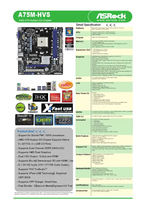
Product BriefCPU MemoryExpansion SlotGraphicsAudioLANRear Panel I/OConnectorSATA3BIOS FeatureSupport CDAccessoriesHardware MonitorOSCertifications The specification is subject to change without notice. The brand and product names are trademarks of their Chipset - Support for Socket FM1 100W processors - AMD A75 Hudson D3 Chipset Supports Native 6 x SATA3, 4 x USB 3.0 Ports- Supports Dual Channel DDR3 2400+(OC)- Supports AMD Dual Graphics - Dual VGA Output : D-Sub and HDMI- Supports Blu-ray Stereoscopic 3D with HDMI 1.4a - 5.1 CH HD Audio (VIA ® VT1705 Audio Codec), Supports THX TruStudio TM- Supports XFast USB Technology, Graphical UEFI BIOS- Supports APP Charger, SmartView- Free Bundle : CyberLink MediaEspresso 6.5 Trial- Micro ATX Form Factor: 8.9-in x 8.5-in, 22.6 cm x 21.6 cm - Support for Socket FM1 100W processors - Supports AMD's Cool 'n' Quiet Technology - UMI-Link GEN2- AMD A75 FCH (Hudson-D3)- Dual Channel DDR3 memory technology - 2 x DDR3 DIMM slots- Supports DDR3 2400+(OC)/1600(OC)/1333/1066/800 non-ECC, un-buffered memory- Max. capacity of system memory: 16GB - 1 x PCI Express 2.0 x16 slot - Supports AMD Dual Graphics- AMD Radeon HD 65XX/64XX graphics in Llano APU - DirectX 11, Pixel Shader 5.0- Max. shared memory 512MB- Dual VGA Output: support HDMI and D-Sub ports by independent display controllers- Supports HDMI 1.4a Technology with max. resolution up to 1920x1200 @ 60Hz- Supports D-Sub with max. resolution up to 1920x1600 @ 60Hz- Supports Auto Lip Sync, Deep Color (12bpc), xvYCC and HBR (High Bit Rate Audio) with HDMI (Compliant HDMI monitor is required)- Supports Blu-ray Stereoscopic 3D with HDMI 1.4a- Supports AMD Steady Video : New video post processing capability for automatic jutter reduction on home/online video - Supports HDCP function with HDMI port- Supports Full HD 1080p Blu-ray (BD) / HD-DVD playback with HDMI port - 5.1 CH HD Audio (VIA VT1705 Audio Codec)- PCIE x1 Gigabit LAN 10/100/1000 Mb/s - Realtek RTL8111E- Supports Wake-On-LAN- Supports LAN Cable Detection- Supports Energy Efficient Ethernet 802.3az - Supports PXEI/O Panel- 6 x SATA3 6.0 Gb/s connectors - 1 x IR header - 1 x CIR header- 1 x Print port header - 1 x COM port header- CPU/Chassis/Power FAN connector - 24 pin ATX power connector - 8 pin 12V power connector - Front panel audio connector- 3 x USB 2.0 headers (support 6 USB 2.0 ports)- 32Mb AMI UEFI Legal BIOS with GUI support - Drivers, Utilities, AntiVirus Software (Trial Version), AMD Live! Explorer, CyberLink MediaEspresso 6.5 Trial, ASRock Software Suite(CyberLink DVD Suite - OEM and Trial; Creative Sound Blaster X-Fi MB - Trial)- 6 x SATA3 6.0 Gb/s connectors, support RAID (RAID 0, RAID 1 and RAID 10), NCQ, AHCI and "Hot Plug" functionsUSB 3.0- 4 x USB 3.0 ports, support USB 1.0/2.0/3.0 up to 5Gb/s - CPU Temperature Sensing - Chassis Temperature Sensing- CPU/Chassis/Power Fan Tachometer - CPU/Chassis Quiet Fan- CPU/Chassis Fan Multi-Speed Control- Voltage Monitoring: +12V, +5V, +3.3V, Vcore- Microsoft Windows 7 / 7 64-bit / Vista / Vista 64-bit / XP / XP 64-bit compliant- FCC, CE, WHQL- ErP/EuP Ready (ErP/EuP ready power supply is required)- Quick Installation Guide, Support CD, I/O Shield - 2 x SATA data cables (optional)AMD A75 Hudson D3 ChipsetUnique Feature- ASRock Extreme Tuning Utility (AXTU)- ASRock Instant Boot - ASRock Instant Flash - ASRock APP Charger - ASRock SmartView - ASRock XFast USB - Hybrid Booster:- ASRock U-COPA75M-HVSDirectX ® 11T r i a lGra Other A75 MotherboardConfigurationModel ASRock A75M-HVS Chipset Hudson D3CPU AMD A8-3850 2.9 GHzRAM Kingston DDRIII 2250 2GB*2VGA Card ATI HD 6600HDDWestern Digital WD6402AAEXOther A75 Motherboard Hudson D3AMD A8-3850 2.9 GHzKingston DDRIII 2250 2GB*2ATI HD 6600Western Digital WD6402AAEX* Graphical Visual Experience * Mouse Enabling* Supports 3TB bootable HDDThe fastest video media conversation softwareThe best Apple charge companion4 x USB 3.0 5Gb/s6 x SATA3 6Gb/sT r i alApp ChargerMediaEspresso 6.5 TrialUSB 3.0SATA3ASRock Extreme Tuning Utility (AXTU) is an all-in-one software to fine-tune different features in an userfriendly interface, which includes Hardware Monitor, Fan Control, Overclocking, OC DNA and IES.Delivering the fullest audio experience for games, music and movies.SATA3 SupportThe AMD A75 Hudson D3 chipset provides native support of USB 3.0 and SATA3. ASRock A75 Motherboard Series provide rich storage options including 4 USB 3.0 and 5 SATA3 ports.New Video Post ProcessingCapability : automatic jitter reduction on home/online video.BeforeAfter。
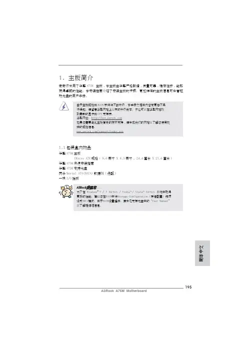
195ASRock A75M Motherboard簡體中文1. 主板簡介謝謝你采用了華擎A75M 主板,本主板由華擎嚴格制造,質量可靠,穩定性好,能夠獲得卓越的性能。
本安裝指南介紹了安裝主板的步驟。
更加詳細的主板信息可參看驅動光盤的用戶手冊。
1.1包裝盒內物品華擎A75M 主板 (Micro ATX 規格: 9.6英吋 X 8.5英吋, 24.4厘米 X 21.6厘米)華擎A75M 快速安裝指南華擎A75M 支持光盤兩條Serial ATA(SATA)數據線(選配)一塊I/O擋板ASRock提醒您...為了在 Windows ®7 / 7 64-bit / Vista TM / Vista TM 64-bit 系統中取得更好的性能,建議您在BIOS中將Storage Configuration(存儲配置)選項設成AHCI模式。
關于BIOS設置程序,請參見支持光盤中的“User Manual”以了解相詳細信息。
1.2主板規格架构 - Micro ATX規格:9.6英吋 X 8.5英吋, 24.4厘米 X 21.6厘米- 全固態電容設計處理器 - FM1插槽支持100W處理器- 支持 AMD Cool ‘n’ Quiet™冷靜技術- UMI-Link GEN2芯片組 - AMD A75 FCH (Hudson-D3)系統內存 - 支持雙通道DDR3內存技術(見警告1)- 配備2個DDR3 DIMM插槽- 支持DDR3 2400+(超頻)/1866/1600/1333/1066/800 non-ECC、un-buffered內存(見警告2)- 最高支持16GB系統容量(見警告3)擴展插槽 - 1 x PCI Express 2.0 x16插槽- 1 x PCI Express 2.0 x1插槽- 2 x PCI插槽- 支持AMD雙顯卡技術板載顯卡 - AMD Radeon HD 65XX/64XX顯卡- DirectX 11、Pixel Shader 5.0技術- 最大共享內存512MB(見警告4)- 雙VGA輸出:通過獨立顯示控制器提供HDMI和D-Sub接口- 支持HDMI 1.4a,最高分辨率達1920x1200 @ 60Hz- 支持D-Sub,最高分辨率達1920x1600 @ 60Hz- 支持HDMI,可支持Auto Lip Sync、Deep Color (12bpc)、xvYCC與HBR(高位速音頻)(需配備兼容HDMI的顯示器)(詳見警告5)- 支持藍光立体3D和HDMI 1.4a- 支持AMD Steady Video TM:最新視頻后處理能力,可為家庭/在線視頻提供自動降低抖動的功能- 通過HDMI接口支持HDCP功能- 通過HDMI接口可播放10800線藍光光盤(BD) / HD-DVD光盤 音效 - 7.1聲道高保真音頻,支持內容保護功能(Realtek ALC892音頻編解碼器)簡體中文- 支持優質藍光音效- 支持THX TruStudio TM板載LAN功能 - PCIE x1 Gigabit LAN 10/100/1000 Mb/s- Realtek RTL8111E- 支持网路喚醒(Wake-On-LAN)- 支持網路線偵測功能- 支持Energy Efficient Ethernet 802.3az- 支持PXE196ASRock A75M Motherboard197ASRock A75M Motherboard簡體中文Rear Panel I/O 界面I/O- 1個PS/2 鼠標接口 (后面板輸入/ - 1個PS/2 鍵盤接口 輸出接口) - 1個D-Sub 接口 - 1個HDMI 接口- 1個光纖SPDIF 輸出接口- 2個可直接使用的USB 2.0接口 - 1個eSATA3接口- 4個可直接使用的USB 3.0接口- 1個RJ-45局域网接口與LED 指示燈(ACT/LINK LED 和 SPEED LED)- 高保真音頻插孔:后置喇叭/中置喇叭/低音喇叭/音頻輸入/前置喇叭/麥克風 (見警告6)SATA3 - 5 x SATA3 6.0Gb/s 連接頭,支持RAID (RAID 0, RAID 1和RAID 10),NCQ,AHCI 和熱插拔功能USB 3.0 - 4 x USB 3.0連接頭,支持USB 1.0/2.0/3.0到5Gb/s 連接頭 - 5 x SATA3 6.0Gb/s 連接頭 - 1 x 紅外線模塊接頭- 1 x 消費類紅外線模塊接頭- 1 x 打印機端口接針 - 1 x 串行接口- 1 x HDMI_SPDIF 接頭 - CPU/機箱/電源風扇接頭 - 24針ATX 電源接頭 - 8針12V 電源接頭 - 前置音頻面板接頭- 3 x USB 2.0接口 (可支持6個額外的USB 2.0接口) BIOS - 32Mb AMI BIOS- AMI UEFI Legal BIOS,支持GUI- 支持即插即用(Plug and Play,PnP) - ACPI 1.1 電源管理 - 支持喚醒功能- 支持jumperfree 免跳線模式- DRAM、VDDP、SB 電壓多功能調節器支持光盤 - 驅動程序,工具軟件,殺毒軟件(測試版本),AMD Live! Explorer, AMD Fusion, CyberLink MediaEspresso 6.5試用版, 華擎軟件套裝(CyberLink DVD Suite - OEM 試用版)獨家功能 - ASRock Extreme Tuning Utility (AXTU)(詳見警告7)- 華擎即時開機功能- 華擎Instant Flash(見警告8)- 華擎APP Charger(見警告9)- 華擎SmartView(見警告10)- 華擎XFast USB(見警告11)- 華擎開/關播放技術(見警告12)- Hybrid Booster(安心超頻技術):- ASRock U-COP(見警告13)硬件監控器 - CPU溫度偵測- 主板溫度偵測- CPU/機箱/電源風扇轉速計- CPU/机箱靜音風扇- CPU/機箱風扇多速控制- 電壓範圍:+12V, +5V, +3.3V, 核心電壓操作系統 - Microsoft®Windows®7/7 64位元/Vista TM/Vista TM 64位元/XP SP3/XP 64位元适用于此主板認證 - FCC, CE, WHQL- 支持ErP/EuP(需要同時使用支持ErP/EuP的電源供應器)(見警告14)* 請參閱華擎網站了解詳細的產品信息: 警告請了解超頻具有不可避免的風險,這些超頻包括調節BIOS設置、運用異步超頻技術或使用第三方超頻工具。
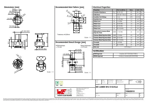
Dimensions: [mm]Scale - 1:174960001045398TD+CTD TD-RD+CRD RD-6NC 1NC 2NC 7NC GND GND749600010749600010749600010T e m p e r a t u r eT pT L749600010Cautions and Warnings:The following conditions apply to all goods within the product series of WE-LANMX ofWürth Elektronik eiSos GmbH & Co. KG:General:•This electronic component is designed and manufactured for use in general electronic equipment.•Würth Elektronik must be asked for written approval (following the PPAP procedure) before incorporating the components into any equipment in fields such as military, aerospace, aviation, nuclear control, submarine, transportation (automotive control, train control, ship control), transportation signal, disaster prevention, medical, public information network etc. where higher safety and reliability are especially required and/or if there is the possibility of direct damage or human injury.•Electronic components that will be used in safety-critical or high-reliability applications, should be pre-evaluated by the customer.•The component is designed and manufactured to be used within the datasheet specified values. If the usage and operation conditions specified in the datasheet are not met, the wire insulation may be damaged or dissolved.•Do not drop or impact the components, the component may be damaged.•Würth Elektronik products are qualified according to international standards, which are listed in each product reliability report. Würth Elektronik does not warrant any customer qualified product characteristics beyond Würth Elektroniks’ specifications, for its validity and sustainability over time.•The responsibility for the applicability of the customer specific products and use in a particular customer design is always within the authority of the customer. All technical specifications for standard products also apply to customer specific products.Product specific:Soldering:•The solder profile must comply with the technical product specifications. All other profiles will void the warranty.•All other soldering methods are at the customers’ own risk.•Strong forces which may affect the coplanarity of the components’ electrical connection with the PCB (i.e. pins), can damage the part, resulting in avoid of the warranty.Cleaning and Washing:•Washing agents used during the production to clean the customer application might damage or change the characteristics of the wire insulation, marking or plating. Washing agents may have a negative effect on the long-term functionality of the product.•Using a brush during the cleaning process may break the wire due to its small diameter. Therefore, we do not recommend using a brush during the PCB cleaning process.Potting:•If the product is potted in the customer application, the potting material might shrink or expand during and after hardening. Shrinking could lead to an incomplete seal, allowing contaminants into the core. Expansion could damage the component. We recommend a manual inspection after potting to avoid these effects.Storage Conditions:• A storage of Würth Elektronik products for longer than 12 months is not recommended. Within other effects, the terminals may suffer degradation, resulting in bad solderability. Therefore, all products shall be used within the period of 12 months based on the day of shipment.•Do not expose the components to direct sunlight.•The storage conditions in the original packaging are defined according to DIN EN 61760-2.•The storage conditions stated in the original packaging apply to the storage time and not to the transportation time of the components. Handling:•Violation of the technical product specifications such as exceeding the nominal rated current will void the warranty.•Applying currents with audio-frequency signals may result in audible noise due to the magnetostrictive material properties.•For direct GND connection between the LANMX and the panel, the area under the nut on both sides of the panel, needs to be without coatingThese cautions and warnings comply with the state of the scientific and technical knowledge and are believed to be accurate and reliable.However, no responsibility is assumed for inaccuracies or incompleteness.Würth Elektronik eiSos GmbH & Co. KGEMC & Inductive SolutionsMax-Eyth-Str. 174638 WaldenburgGermanyCHECKED REVISION DATE (YYYY-MM-DD)GENERAL TOLERANCE PROJECTIONMETHODLuRa001.0012021-01-29DIN ISO 2768-1mDESCRIPTIONWE-LANMX M12 D VerticalORDER CODE749600010SIZE/TYPE BUSINESS UNIT STATUS PAGEImportant NotesThe following conditions apply to all goods within the product range of Würth Elektronik eiSos GmbH & Co. KG:1. General Customer ResponsibilitySome goods within the product range of Würth Elektronik eiSos GmbH & Co. KG contain statements regarding general suitability for certain application areas. These statements about suitability are based on our knowledge and experience of typical requirements concerning the areas, serve as general guidance and cannot be estimated as binding statements about the suitability for a customer application. The responsibility for the applicability and use in a particular customer design is always solely within the authority of the customer. Due to this fact it is up to the customer to evaluate, where appropriate to investigate and decide whether the device with the specific product characteristics described in the product specification is valid and suitable for the respective customer application or not.2. Customer Responsibility related to Specific, in particular Safety-Relevant ApplicationsIt has to be clearly pointed out that the possibility of a malfunction of electronic components or failure before the end of the usual lifetime cannot be completely eliminated in the current state of the art, even if the products are operated within the range of the specifications.In certain customer applications requiring a very high level of safety and especially in customer applications in which the malfunction or failure of an electronic component could endanger human life or health it must be ensured by most advanced technological aid of suitable design of the customer application that no injury or damage is caused to third parties in the event of malfunction or failure of an electronic component. Therefore, customer is cautioned to verify that data sheets are current before placing orders. The current data sheets can be downloaded at .3. Best Care and AttentionAny product-specific notes, cautions and warnings must be strictly observed. Any disregard will result in the loss of warranty.4. Customer Support for Product SpecificationsSome products within the product range may contain substances which are subject to restrictions in certain jurisdictions in order to serve specific technical requirements. Necessary information is available on request. In this case the field sales engineer or the internal sales person in charge should be contacted who will be happy to support in this matter.5. Product R&DDue to constant product improvement product specifications may change from time to time. As a standard reporting procedure of the Product Change Notification (PCN) according to the JEDEC-Standard inform about minor and major changes. In case of further queries regarding the PCN, the field sales engineer or the internal sales person in charge should be contacted. The basic responsibility of the customer as per Section 1 and 2 remains unaffected.6. Product Life CycleDue to technical progress and economical evaluation we also reserve the right to discontinue production and delivery of products. As a standard reporting procedure of the Product Termination Notification (PTN) according to the JEDEC-Standard we will inform at an early stage about inevitable product discontinuance. According to this we cannot guarantee that all products within our product range will always be available. Therefore it needs to be verified with the field sales engineer or the internal sales person in charge about the current product availability expectancy before or when the product for application design-in disposal is considered. The approach named above does not apply in the case of individual agreements deviating from the foregoing for customer-specific products.7. Property RightsAll the rights for contractual products produced by Würth Elektronik eiSos GmbH & Co. KG on the basis of ideas, development contracts as well as models or templates that are subject to copyright, patent or commercial protection supplied to the customer will remain with Würth Elektronik eiSos GmbH & Co. KG. Würth Elektronik eiSos GmbH & Co. KG does not warrant or represent that any license, either expressed or implied, is granted under any patent right, copyright, mask work right, or other intellectual property right relating to any combination, application, or process in which Würth Elektronik eiSos GmbH & Co. KG components or services are used.8. General Terms and ConditionsUnless otherwise agreed in individual contracts, all orders are subject to the current version of the “General Terms and Conditions of Würth Elektronik eiSos Group”, last version available at .Würth Elektronik eiSos GmbH & Co. KGEMC & Inductive SolutionsMax-Eyth-Str. 174638 WaldenburgGermanyCHECKED REVISION DATE (YYYY-MM-DD)GENERAL TOLERANCE PROJECTIONMETHODLuRa001.0012021-01-29DIN ISO 2768-1mDESCRIPTIONWE-LANMX M12 D VerticalORDER CODE749600010SIZE/TYPE BUSINESS UNIT STATUS PAGE。
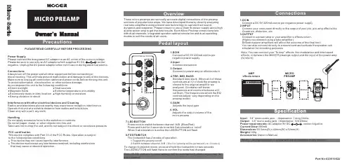
PLEASE READ CAREFULLY BEFORE PROCEEDINGInterference with other electrical devices and CleaningRadios and televisions placed nearby may experience reception interference. Operate this unit at a suitable distance from radios and televisions.Clean only with a soft, dry cloth.Power SupplyPlease connect the designated AC adapter to an AC outlet of the correct voltage. Please be sure to use only an AC adapter which supplies 9V DC, ,center negative. Unplug the AC power adapter when not in use or during electrical storms. HandlingDo not apply excessive force to the switches or controls. Do not let paper, metal, or other objects into this unit.Take care not to drop the unit, and do not subject it to shock or excessive pressure. FCC certificationThis device complies with Part 15 of the FCC Rules. Operation is subject to the following two conditions:This device may not cause harmful interference.This device must accept any interference received, including interference that may cause undesired operation.ConnectionsAlways turn off the power and all other equipment before connecting ordisconnecting. This will help prevent malfunction and damage to any of the devices. Make sure to unplug all connection cables and power cords before moving this unit. To avoid deformation, discoloration, or other serious damage,do not expose this unit to the following conditions: Direct sunlight Magnetic fields Excessively dusty or dirty location Strong vibration or shockExtreme temperature or humidity High humidity or moisture Heat sources*Notes :Any specification’s update will not be amended in this manual.These micro preamps are sonically accurate digital recreations of the preamp sections of popular tube amps. We have developed these by directly analyzing real tube amplifiers using a brand new technology to capture their sound,dynamics and response. Please ensure to use a clean 9v power supply and a high quality power amp to get the best results. Each Micro Preamp comes complete with dual channels, integrated speaker cabinet simulation and dual operating modes to suit the needs of all users.2.InputConnect instrument3.OutputConnect to power amp or effects return4.TRE, MID, BASSStandard tone stack. When all 3 of these controls are at 12 o'clock the preamp is closest to the original amplifier we analyzed. Clockwise will boostfrequencies and counterclockwise will cut them. The frequencies which the EQ controls adjust, vary depending on the preamp model.5.GAINAdjusts the input gain6.VOLAdjusts the output volume of the micro preamp1. D CINConnect a DC 9V 220mA centre pin negative power supply 8.FOOTSWITCHThe footswitch has 2 modes of operation 1.Toggles the preamp on/off2.Switch between channel A/B (The micro preamp will be permanently on in mode 2)7.LED BUTTONPress once to switch between channel A/B (Blue/Red)Press and hold for 2 seconds to switch Cab simulation on/off When Cab simulation is active the LED BUTTON will flash To change footswitch mode, press and hold the footswitch for two seconds. The LED BUTTON will flash twice to confirm the mode has changed.Note: All EQ, gain and volume settings will be automatically stored separately for each channel.1.DCINConnect a DC 9V 220mA centre pin negative power supply 2.INPUTConnect your instrument directly or the output of your pre, pre-amp effects like Overdrive, distortion, etc.3.OUTPUTConnect to a power amp or your amplifier’s effects return. (Highly recommend using a tube amplifier)Different power amplifiers will affect the outcome of the final tone.You can also connect directly to a sound card and activate the speaker cab simulation for recording purposesNote: You can connect your "fx loop" effects, like modulation and time based effects, in between the MOOER preamps output and the input of the power ampInput :1/4” mono audio jack.(Impedance: 1 meg Ohms )Output :1/4” mono audio jack (Impedance: 100 Ohms )Power requirements: AC adapter 9V DC , center negative. Current Draw:300mADimensions :93.5mm(D) x 42mm(W) x 52mm(H)Weight:160gAccessories :Owner’s ManualPart No:620010622。

Important NoticesImproper handling of a vehicle , especially while raised and supported by jack stands, ramps or other mechanical means, can cause serious bodily injury or even death. It is strongly rec-ommended that a trained, experienced mechanic, with proper equipment, do the installation.The seller nor the manufacturer assumes no liability, expressed or implied, for the improper installation or use of this product or its components. Before using, the user shall determine the suitability of the products for it’s intended use. The user assume all responsibility and risk in connection there within.It is the buyer’s responsibility to have all suspension, drivetrain, steering, and other compo-nents checked for proper tightness and torque after the fi rst 100 miles and every 3,000 miles by a qualifi ed professional mechanic.Extreme care should be taken while operating your vehicle to prevent vehicle rollover or loss of control. Both can result in serious injury or death. Do not add or modify parts to this kit or use outside it’s intended purpose. Follow all safety regulations and warnings per state and federal laws.Note: Final fi tment of the wheel to caliper is the responsibility of the customer.Note: It is important to read and understand this ENTIRE installation manual, before starting the installation.Kit Contents1 Pair of calipers w/pads2 Rotors2 Retaining plate2 Preload spacers (C-clip applications)4 Caliper bolts8 T-bolts8 Nuts2 Disc brake mounting plate assembly (1 Left and 1 Right)1 stainless steel brake line kitTools and Equipment That May Be RequiredDifferent models and years of vehicle use different-sized fasteners, and every effort has been taken to correctly identify the proper sized tool for each step of the installation. Occasionally, however, manufacturers use alternate fasteners, so it’s advisable to check that each tool cor-rectly fi ts the fastener before loosening or tightening it. The following tools and equipment may be needed:9/16” socket wrench12mm socket14mm wrenchTorque wrenches capable of 10-148 lb-ft settingsSeveral ragsSmall funnel or suitable means of fi lling master cylinder reservoirBrake bleed bottle1 pair of jack stands or other means of supporting vehicleHydraulic pressPair of PliersStep 1-Remove WheelsWARNING - Brake fl uid will damage most painted surfaces. Immediately clean spilled brake fl uid from any painted surfaces. Be sure the cap is securely installed on the master cylinder. If the cap is loose or removed, it is likely more fl uid willdrip.Note: All Photographs Show Left Side Installation, unless noted otherwise.Break loose the lug nuts on both rear wheels before jacking up the car.Refer to the Owners Manual for the correct location when jacking up the vehicle. Jack up the vehicle and secure on a pair of jack stands. Never leave any vehicle supported with only a jack - always use jack-stands.After securing the vehicle at a convenient height, remove the rear wheels.Note: If you remove the bottom lug nut last while holding the bottom of the tire, it will lessen the chances of the wheel tilting on it’s own and make removal easier.Step 2 -Removal of Drum Brakes and AxleRemove brake drums from thebrake assembly.Remove the hard line from thewheel cylinder attached to thebacking plate.For c-clip applications- Removethe differential cover, unbolt thecross shaft and remove it from thevehicle. See factory service manualfor additional information.Using a 9/16” socket, remove thefour nuts that hold each axle shaftinto the axle and remove the axleshafts from the axle. Some leakagemay occur.Remove the backing plate from theaxle housing.Wipe clean grease and contami-nants from all surfaces.For semi-fl oat applications- Pressthe old bearings and seals fromthe axle shafts. C-clip applicationsdo not need the removal of the oldbearings and seals unless parts areneeded to be replaced.Install the disc brake mounting plate onto the axle flange with new supplied retaining bolts. The mounting plate is directional, insurethat the plate is installed on the correct side.Step 3 -Install Disc Mounting PlateIn order to install this kit, remove the factory bolts from the axle fl ange. If installing on a C-clip application do not remove the fac-tory bolts.Install the supplied bolts (longer than factory bolts) in the axle fl ange.Adjust the internal parking brake shoes with the adjuster until there is just enough room to slide the ro-tor over the shoes. Refer to the fac-tory service manual for additional information.STEP 4 -Install Axle ShaftsApply grease to the outside of the bearing seal assembly and slide the preload spacer onto the seal. The grease will help hold the spacer in place.Slide the axle shaft into the axle housing by hand, lining it up with the differential. The axle shaft should not be forced, damage mayoccur.On C-clip retained axles, slide the axles all the way into the axle hous-ing using care to avoid damage to the splines or the bearing surface. Reinstall the C-clip and the cross shaft. Ensure that all old silicone is cleaned from the differential hous-ing and the differential cover, and reinstall the differential cover using a new gasket or silicone. Fill thehousing with new oil.Using a hydraulic press, press the new bearing and retaining collar onto the axle shaft. Refer to the factory service manual for more details.Grease the shaft where the axle shaft seal will be installed, theninstall the seal.Install the retaining plate and new preload spacer on axle shaft. Notice the direction the preload spacer is facing in the photo to the right. The chamfer side faces inboard.STEP 5 -Install the Rotor and CaliperInstall the rotor on the axle.Install the brake pads in the caliper.Using a 12mm socket wrench in-stall the caliper onto the mounting plate. Torque the bolts to 15-18 ft-lbs.Line up the access holes located on the axle shafts with the retainer bolts. Using a 9/16” socket wrench tighten the four nuts to 25 - 30 ft-lbs.STEP 4 -(Continued)Install Axle ShaftsSTEP 6 -Install Stainless Steel Brake LinesInstall the caliper end of the stainless steel brake line by fi rst placing a copper crush washer on either side of the banjo fi tting.Insert the banjo bolt into the caliper using a 14mm wrench or socket to tighten it. Insert the stainless steel brake line fi tting through the chassis bracket, and screw it onto the hard line fi tting by hand a few turns, to ensure that it is properly engaged. Tighten the hard line fi tting.Check to ensure that the brake line is not binding in any way, nor interfering with any suspension component.Note that you will need to purchase shorter metal brake lines from an automotive pats supplier.If the brake line is not properly routed, a catastrophic failure could occur. If you are unsure that the line is routed properly and safely, do not drive the car. Please call our Tech Support Dept. for assistance if you have any doubt as to the brake line routing.Install the emergency brake cable at the mounting plate and adjust, refer to the factory service manual.If realignment is necessary, loosen the banjo bolt, and realign the brake line, or loosen the inboard end of the line, and slightly re-clock the fitting.Weld the brake line mounting tab onto the axle tube. Install the brake line through the tab and install the c-clip to secure the line.STEP 7-Bleed BrakesComplete installation on both sides of the vehicle before bleeding the system. Note: The calipers and lines will need to fi ll with fl uid, quickly draining the master cylinder reservoir. Keep a close watch on the fl uid level when initially bleeding the system. Do not allow the master cylinder reservoir to run dry and draw in air. Doing so may require the brake system to be serviced by a certifi ed brake technician.Refer to owners manual for torque used on bleed screws.After initially bleeding the system, gently tap the caliper body with a non-marring mallet or hammer to dislodge any small air bubbles and re-bleed.After bleeding, apply a constant pressure to the brake pedal and check all connections, including bleed screws, and both ends of the line for leaks.Brake fl uid will damage most painted surfaces. Immediately clean spilled brake fl uid from any painted surface, including the caliper. Though caliper paint is designed to resist harsh chemicals, prolonged exposure will damage the fi nish.STEP 8-Reinstall wheelsCheck wheel to caliper clearance before installing wheels!Reinstall the wheels and torque the lug nuts to your wheel manufacturer’s specifi cations. It may be necessary to snug the bolts before lowering the vehicle and then torque the wheels when the car is on the ground. Alternatively, an assistant may depress the brake pedal while you tighten the wheel nuts to the proper torque setting.Carefully test-drive the vehicle in a safe area at low speed to insure all components are working correctly.。
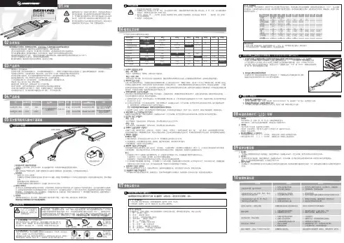
1、启动阶段1)红灯每2秒闪一次,且伴为“哔-,哔-”警示音:电调未检测到油门信号。
2)绿灯闪烁N次:上电时自动进行锂电节数检测,闪烁N次表示当前锂电为N节。
2、行驶阶段1)油门摇杆处于中点区域,红色和绿色LED均熄灭。
2)前进时,红色LED恒亮;当油门处于正向最大(100%油门)时,绿色LED也会点亮。
3)倒退时,红色LED恒亮。
3、相关保护功能触发时,LED状态含义:1)红灯持续闪烁(单闪,“☆,☆,☆”方式闪烁):电池电压太低,电调进入电池低压保护状态。
2)绿灯持续闪烁(单闪,“☆,☆,☆”方式闪烁):电调温度过高,电调进入过热保护状态。
故障现象解决方法可能原因1、电池电压没有输入到电调;1、检查电池与电调是否连接可靠,如有焊接不良,请重新焊好;上电后电机无鸣音,指示灯也未闪亮06编程设定说明08电调状态指示灯(LED)说明09保护功能说明10故障快速处理01声明Seaking Pro 120A • Seaking Pro 160A船用无刷电子调速器使用说明书· 调试请将船模架起,确保船桨不会碰到人或其他物体,以免发生安全事故。
03产品特色· 轻量化设计,适合竞赛要求。
· 出色的防水性能(160A电调采用塑封工艺,120A电调采用纳米镀膜工艺),一般情况下无需做防水处理即可直接使用(注:使用后请将电调插头吹干,以免锈蚀)。
· 内置超强开关模式BEC,持续电流达到4A,瞬间达到8A,且支持 6V和7.4V 切换,轻松驱动各种强力舵机及高压舵机。
· 采用好盈专利铜片导热技术,配合水冷模块和极低热阻的内部MOSFET,使得电调的耐流能力及可靠性大大增强。
· 使用顶级竞赛核心程序,具有一流的操控手感及丰富的调节选项,适应各种比赛环境。
· 行业首创的超速功能(即:开启Turbo进角),让马达瞬间释放更强动力,轻松超越竞争对手。

PURE PLATINUM A75M安装手册安装手册Sapphire Pure Platinum A75MAMD A75芯片组、FM1 插槽主板第 1 章 - 简介 (3)1-1主机板布局 (3)I/O 背面面板 (4)第 2 章 - 安装 (5)2-1安装前的准备工作 (5)2-2安装 I/O 挡板 (5)2-3固定主板至系统机箱底部 (5)2-4安装 CPU 和风扇散热器 (6)2-5安装系统内存 (7)系统内存结构 (7)安装系统内存 (7)2-6 安装扩展卡 (8)PCI-E扩展插槽 (8)PCI扩展插槽 (8)2-7连接线缆 (9)连接电源线 (9)Cables连接串行ATA/ S-ATA (SATA) 线缆 (9)第3章 – BIOS的设置 (11)3-1 进入BIOS主界面 (11)3-2 控制键位 (11)3-3 主题帮助 (12)3-4 主页 (12)3-5高级(BIOS功能设置) (13)3-6 桥接设备(芯片组功能设置) (21)3-7 启动(启动设置) (23)3-8 安全(安全设置) (24)3-9 超频(超频设置) (25)3-10退出(离开BIOS设置程序) (26)第4章 – 安装设备驱动器 (28)TRIXX工具 (30)第 1 章 - 简介1-1主机板布局下图显示各零件在主板上的位置。
222423216855 2详细介绍请参见下一页:双BIOS(JBIOS)跳线设置 1、2脚短接 无论何时都从主BIOS 引导 2、3脚短接 无论何时都从附BIOS 引导 NC自动切换(出厂设定)I/O 背面面板项目叙述项目叙述项目 叙述 项目叙述1 AMD FM1处理器接口 14Memory Free 按钮 2A75 Hudson D3 芯片组 15Power 按钮 3 DDR3 内存插槽 16Reset 按钮 4 PCI-E 2.0 x16 扩展槽1条 17JCOM 串行接口(搭配顺序式扩展线) 5PCI-E 2.0 x1扩展槽2条 18S/PDIF 插针式接头 6 PCI 扩展槽1条 19前置音频插针式接头 7 APU 节能显示 20CPU 风扇电源接头 8 24针 ATX 电源接口 21SFAN 风扇电源接头 9 8针ATX 12伏电源接口 22主板电池 10 SATA 3.0接口6个 23音频芯片 11 前置面板插针式接头 24双BIOS12 前置USB 2.0 插针式接头2个 25双BIOS 设定;出厂设定为自动 13前置USB 3.0 插针式接头 26I/O 背板接头(详细内容,请看下图)32586第 2 章装2-1安装前的执行任何硬件动作之前,请关闭系统电源,并且通过触摸接地表面,例如电源的金属表面,来释放您身体上的静电2-2安装 I/O 挡板安装主板至机箱前,请先将I/O 挡板放置机箱内侧,使之挡板固定于机箱内。
A75MA-G55主板实用指南一、什么软件可以检测双通道其实双通道完全是硬件的事,只要按主板说明,把内存插在双通道的槽里就是双通道。
微星的主板就是插在同样颜色的2个槽里。
只有软件检测,没有任何意义。
因为检测软件是人编写的,常常错误百出。
现在CPU-Z最新版的1.58版面对A75主板无能为力,举起白旗了。
你能因为CPU-Z检测不出双通道,就不用A75主板?好赖还有软件可以检测出来。
看看这个。
注意,要1.80.1450版本的才可以,老版本是不行的。
先说这一件,其他且听下回。
二、A75主板的北桥是什么名称?A75是南桥的名字,北桥在哪里?一般来讲,北桥负责内存、PCIE以及显卡。
AMD的APU已经把内存控制器和PCIE显卡整合在CPU,因此,北桥在CPU内。
南桥的商品名是A75,研发代码不是A75,芯片上刻的名字也不是A75,而是FCH。
CPU-Z 1.58不仅不能显示内存的通道,还不能正确显示北桥。
AIDA64显示的和CPU-Z不一样。
下载 (90.4 KB)2011-9-5 12:21三、支持DDR3 1866内存,容量最高16GBA75主板和APU支持DDR3 1866内存,实际测试完全可以。
BIOS设置DDR3 18661、DDR3 1600 2GBx4 超18664条2GB 1600,总共8GB,超1866很轻松。
2、DDR3 1600 4GBx4 超18664条4GB 1600,总共16GB,超1866很轻松。
有些1600内存超1866,需要手动设置一下时序,或者加一点电压。
品质好的就不需要。
四、集显设置1.2版BIOS设置,Integrated Graphics设置为Force。
然后可以设置显存容量。
1.3版BIOS设置,Initiate Graphic Adapter设置为IGD。
Integrated Graphics设置为Force。
设置显存容量五、混合交火混合交火仅支持Windows 7,不支持XP。
主板与 cpu 配置 AMD Socket FM1 AMD AM3+ AMD CPU on Board Intel Socket 1155 Intel Socket 1156 Intel Socket 1366 Intel Socket 775 Intel CPU on Board AMD AM3 外围配件M5A97 EVO 具备数字供电设计的第 2 代双智能处理器: 全新标准 图形化界面的 UEFI BIOS(EZ 模式) – 灵活 & 易用的 BIOS 界面 自动加速 -达到整体系统性能的提升! 支持 USB 3.0 & SATA 6Gb/s –双倍存取、双倍便利!支持四路 GPU CrossFireX!F1A75-M图形化界面的 UEFI BIOS(EZ 模式)– 灵活 & 易用的 BIOS 界面 MemOK! – 任何内存皆 OK! 原生支持 USB 3.0/SATA 6Gb/s -双倍存取、双倍便利 TurboV - 体验即时超频所带来心跳加速的感觉! AI Suite II 智能管家 2 - 一键存取所有华硕的创新功能M5A97 PRO 具备数字供电设计的第 2 代双智能处理器: 全新标准 图形化界面的 UEFI BIOS(EZ 模式)– 灵活 & 易用的 BIOS 界面 自动加速 -达到整体系统性能的提升! 支持 Quad-GPU CrossFireX!F1A75-M PRO具备 DIGI+VRM 数字供电设计的第 2 代双智能处理器: 全新标 准图形化界面的 UEFI BIOS(EZ 模式)– 灵活 & 易用的 BIOS 界面 AI Suite II 智能管家 2 - 一键存取所有华硕的创新功能 支持 Quad USB 3.0/SATA 6Gb/s -双倍存取、双倍便利 支持 Multi-GPU CrossFireX!Maximus IV GENE-ZLGA1155 插槽支持第二代英特尔® 酷睿™ i7/酷睿™ i5/酷睿 ™ i3 处理器 英特尔® Z68 高速芯片组 双通道 DDR3 2200 (超频) Mem TweakIt -动态即时调校,内存效率测量! ROG Connect 及 GPU TweakIt 内建 SupremeFX X-Fi 2 GameFirst / Intel Gb LANMaximus IV Extreme-Z Mem TweakIt: 动态即时调校,内存效率测量! ROG Connect: 即插即超频,基于硬件的实时超频! ROG iDirect : 立即从您的 iPhone 或 iPad 启动您的电脑! RC Bluetooth: 突破传统超频的所有障碍! Extreme Engine Digi+:模拟与数字设计元素的强大组合! USB BIOS Flashback: 更新 BIOS 从未如此轻松! AMD Socket FM1 AMD A55 AMD A75 AMD A55F1A55华硕 TurboV - 体验即时超频所带来心跳加速的感觉!图形化界面的 UEFI BIOS(EZ 模式)– 灵活 & 易用的 BIOS 界面 AI Suite II 智能管家 2 - 一键存取所有华硕的创新功能 支持 Multi-GPU CrossFireX! 华硕 Anti-Surge(电涌全保护)- 保护系统安全!F1A55-MProtect 3.0 - EPU 智能节能处理器, 电涌全保护, EMI 防辐射及 全固态电容图形化界面的 UEFI BIOS(EZ 模式)– 灵活 & 易用的 BIOS 界面 MemOK! – 任何内存皆 OK! 华硕 TurboV - 体验即时超频所带来心跳加速的感觉! AI Suite II 智能管家 2 - 一键存取所有华硕的创新功能F1A55-M LE图形化界面的 UEFI BIOS(EZ 模式)– 灵活 & 易用的 BIOS 界面 AI Suite II 智能管家 2 - 一键存取所有华硕的创新功能 支持 Multi-GPU CrossFireX! 华硕 Anti-Surge(电涌全保护)-保护系统安全!F1A55-M LX PLUS Protect 3.0 - 保护地球、保护系统、保护您! 100% 高品质全固态电容 图形化界面的 UEFI BIOS(EZ 模式)– 灵活 & 易用的 BIOS 界面 AI Suite II 智能管家 2 - 一键存取所有华硕的创新功能 支持 Multi-GPU CrossFireX!F1A55-V支持 Multi-GPU CrossFireX!图形化界面的 UEFI BIOS(EZ 模式)– 灵活 & 易用的 BIOS 界面 MemOK! – 任何内存皆 OK! 华硕 TurboV - 体验即时超频所带来心跳加速的感觉! AI Suite II 智能管家 2 - 一键存取所有华硕的创新功能 AMD A75AMD A75F1A75Protect 3.0 - EPU 智能节能处理器, 电涌全保护, EMI 防辐射及 固态电容图形化界面的 UEFI BIOS(EZ 模式)– 灵活 & 易用的 BIOS 界面 MemOK! – 任何内存皆 OK! 原生支持 USB 3.0/SATA 6Gb/s -双倍存取、双倍便利 AI Suite II 智能管家 2 - 一键存取所有华硕的创新功能F1A75-M图形化界面的 UEFI BIOS(EZ 模式)– 灵活 & 易用的 BIOS 界面 MemOK! – 任何内存皆 OK! 原生支持 USB 3.0/SATA 6Gb/s -双倍存取、双倍便利 TurboV - 体验即时超频所带来心跳加速的感觉! AI Suite II 智能管家 2 - 一键存取所有华硕的创新功能F1A75-M LE图形化界面的 UEFI BIOS(EZ 模式)– 灵活 & 易用的 BIOS 界面 AI Suite II 智能管家 2 - 一键存取所有华硕的创新功能 支持 USB 3.0/SATA 6Gb/s -双倍存取、双倍便利 支持 Multi-GPU CrossFireX!F1A75-M PRO具备 DIGI+VRM 数字供电设计的第 2 代双智能处理器: 全新标 准图形化界面的 UEFI BIOS(EZ 模式)– 灵活 & 易用的 BIOS 界面 AI Suite II 智能管家 2 - 一键存取所有华硕的创新功能 支持 Quad USB 3.0/SATA 6Gb/s -双倍存取、双倍便利 支持 Multi-GPU CrossFireX!F1A75-V EVO具备 DIGI+VRM 数字供电设计的第 2 代双智能处理器: 全新标 准图形化界面的 UEFI BIOS(EZ 模式)– 灵活 & 易用的 BIOS 界面 自动加速- 达到极致且稳定的超频成果! 原生支持 USB 3.0/SATA 6Gb/s -双倍存取、双倍便利!AI Suite II 智能管家 2 - 一键存取所有华硕的创新功能F1A75-V PRO具备 DIGI+VRM 数字供电设计的第 2 代双智能处理器: 全新标 准图形化界面的 UEFI BIOS(EZ 模式)– 灵活 & 易用的 BIOS 界面 自动加速- 达到极致且稳定的超频成果! 原生支持 USB 3.0/SATA 6Gb/s -双倍存取、双倍便利! AI Suite II 智能管家 2 - 一键存取所有华硕的创新功能。
华硕笔记本BIOS设置详解在DIY世界中混着,在DIY硬件论坛跑着,对于一个热衷于DIY的我们来说,最大的乐趣就是去折腾,去发觉计算机的潜能!对老玩家来说DIY可谓是很简单,Bios就是小菜一叠,可对于DIY 界小白来说,已提到Bios,就会感觉是个很深奥的问题!甚至一些老玩家,提到Bios,照样还是有一副无辜的样子!Bios涉及了很多计算机内部硬件和性能差数设置,对于一般不懂电脑的人来说有一定的危险性,加之一般Bios里面都是英文,这个对于英语好的人来说没有问题,但是这毕竟是中国,还有很多人对英语并不是很懂,所以很多人不敢轻易涉足!为了把大家的这些疑惑解决,我利用空闲时间把Bios的设置用图文解释给大家看看,希望能给一部分人一些帮助!这次,和大家介绍一下如何设置华硕主板bios,我找了两种Bios 的计算机分别是:华硕的AMI BIOS和升技的AWARD BIOS,这也是目前两种主流的Bios,及算是不同品牌的主板,他们的Bios也是与这两种Bios的功能和设置大同小异,但是一般不同的主板及算是同一品牌的不同型号的主板,他们的Bios又还是有区别的,所以一般不同型号主板的Bios不能通用!先以华硕的AMI Bios为例,介绍一下AMI Bios的设置:开启计算机或重新启动计算机后,在屏幕显示如下时,按下“Del”键就可以进入Bios的设置界面要注意的是,如果按得太晚,计算机将会启动系统,这时只有重新启动计算机了。
大家可在开机后立刻按住Delete键直到进入Bios。
有些品牌机是按F1进入Bios设置的,这里请大家注意!进入后,你可以用方向键移动光标选择Bios设置界面上的选项,然后按Enter进入子菜单,用ESC键来返回主单,用PAGE UP和PAGE DOWN键或上下( ↑↓ )方向键来选择具体选项回车键确认选择,F10键保留并退出Bios设置。
接下来就正式进入Bios的设置了!首先我们会看到(如图2)一.Main(标准设定)此菜单可对基本的系统配置进行设定。
d B75M-PLUS使 用 手 冊iiT8250第一版(�������20�3 年 4 月發行Offer to Provide Source Code of Certain Software This product may contain copyrighted software that is licensed under the General Public License (“GPL”) and under the Lesser General Public License Version (“LGPL”). The GPL and LGPL licensed code in this product is distributed without any warranty. Copies of these licenses are included in this product.You may obtain the complete corresponding source code (as defined in the GPL) for the GPL Software, and/or the complete corresponding source code of the LGPL Software (with the complete machine-readable “work that uses the Library”) for a period of three years after our last shipment of the product including the GPL Software and/or LGPL Software, which will be no earlier than December 1, 2011, either (1) for free by downloading it from /download;or (2) for the cost of reproduction and shipment, which is dependent on the preferred carrier and the location where you want to have it shipped to, by sending a request to:ASUSTeK Computer Inc.Legal Compliance Dept.15 Li Te Rd.,Beitou, Taipei 112Taiwan In your request please provide the name, model number and version, as stated in the About Box of the product for which you wish to obtain the corresponding source code and your contact details so that we can coordinate the terms and cost of shipment with you.The source code will be distributed WITHOUT ANY WARRANTY and licensed under the same license as the corresponding binary/object code.This offer is valid to anyone in receipt of this information.ASUSTeK is eager to duly provide complete source code as required under various Free Open Source Software licenses. If however you encounter any problems in obtaining the full corresponding source code *************************************************************************,statingthe product and describing the problem (please do NOT send large attachments such as source code archives etc to this email address).版權說明©ASUSTeK Computer Inc. All rights reserved. 華碩電腦股份有限公司保留所有權利本使用手冊包括但不限於其所包含的所有資訊皆受到著作權法之保護,未經華碩電腦股份有限公司(以下簡稱「華碩」)許可,不得任意地仿製、拷貝、謄抄、轉譯或為其他利用。
华碩 BIOS设定(shè dìnɡ)方式說明BIOS(基本輸入輸出系統)为出厂時燒錄在主机板上FlashROM之程式,其扮演著硬体与作业系統溝通的角色,透过(tòu ɡuò)BIOS可设定系統操作模式及硬体之相关參数。
系統关机時,BIOS会先進行关机自我測試 (POST)。
此時,按下<Del>鍵即可進入BIOS设定主画面。
其功能及操作(cāozuò)方式說明如下: 【StandardCMOSSetup】系統基本(jīběn)參数设定此选項之功能主要为设定系統基本參数。
使用者可透过(tòu ɡuò)移動亮棒的方式來选择欲设定的項目,用<PageUp>及<PageDown>鍵來修改內容。
在每一选項中,您可按<F1>鍵來顯示該选項可供选择之內容。
Date(日期)设定目前日期。
可设定之範圍为:Month(月):1至12Day(日):1至31Year(年):至2079Time(時間)设定目前時間。
可设定之範圍为:Hour(時):00至23Minu7te(分):00至59Second(秒):00至59HardDisks(硬盘)此选項用來设定系統中所有IDE硬盘(PrimaryMaster/Slave;SecondaryMaster/Slave)之類型。
各选項說明如下: Auto:允許系統关机時自動偵測硬盘類型並加以设定。
None:未安裝硬盘。
User:允許使用者自行设定(shè dìnɡ)硬盘之相关參数。
包括CYLS(磁柱数),HEAD(讀寫頭数),PRECOMP(寫入預補償),LANDZ(放位置)。
在硬盘机所附之說明書均磁頭停詳載這些規格。
[請注意(zhù yì)]:BIOS不支援SCSI硬盘之设定。
至於MODE的选項有三種:1.NORMAL模式(móshì):为傳統之標準模式(móshì),支援硬盘机容量最高至528MB。