华硕电脑笔记本A42J说明书
- 格式:pdf
- 大小:3.70 MB
- 文档页数:30
华硕K42JR或华硕A42J安装XP的完美解决方案华硕的这款K42JR(A42J)笔记本,需要说明一下,K42JR 和A42J其实是同一个型号,只不过一种是黑色,一种是咖啡色的。
另外,K42JR好像是在华东和华北地区销售的,A42J则在华南地区销售。
除此之外,这两款机子没有任何不同!该款笔记本出厂时预装的是正版的WIN7 X64的家庭基础版。
相信有的朋友用不惯这个系统,会找XP来安装。
经测试,这款笔记本是能完美地支持XP系统的,指的是笔记本的所有硬件都能完美支持K42JR的。
但是安装XP时会碰到一些小问题,下面就是我安装的体会,指导你如何解决这些讨厌的小问题。
1、安装XP时为什么会出现蓝屏?解答:对于这款机子,安装XP时出现蓝屏是因为“安装盘”中缺少HM55主板的SATA驱动,解决的办法是开机后当出现华硕标志的时候,按F2或Delete键进入BIOS中,将AHCI的硬盘驱动模式改为IDE模式,就能顺利安装了。
查找BIOS时,看到带有“SATA …………”的那项就是需要调整的了。
2、安装完XP后,一般在——我的电脑——属性——硬件——设备管理器中会有一项“PCI简易通讯器”不能识别,这一项有人说是猫的驱动,其实不是的,这一项是主板芯片驱动——“Intel(R) Management Engine Components”里的一项驱动而已。
下载“1.2.14.0”这个版本。
安装后,就能识别了。
当然也可以用“驱动人生2010”这个自驱驱动搜索来安装,目前也只有驱动人生能识别——“PCI简易通讯器”,其他的如“驱动精灵”等是不能识别的。
3、如何安装SATA驱动?如果你想用AHCI模式,须用已集成了HM55—SATA的XP驱动光盘来安装;但目前I5-CPU的笔记本是最新的笔记本,一般的GHOST XP或安版的XP都未集成HM55的SATA驱动进去。
所以你装好未集成相关SATA驱动的XP系统后,就必须另外安装驱动了。

Quick Start GuideCopyright © 2013 ASUSTeK COMPUTER INC.All Rights Reserved.No part of this manual, including the products and software described in it, may be reproduced, transmitted, transcribed, stored in a retrieval system, or translated into any language in any form or by any means, except documentation kept by the purchaser for backup purposes, without the express written permission of ASUSTeK COMPUTER INC. (“ASUS”).Product warranty or service will not be extended if: (1) the product is repaired, modified or altered, unless such repair, modification of alteration is authorized in writing by ASUS; or (2) the serial number of the product is defaced or missing.ASUS PROVIDES THIS MANUAL “AS IS” WITHOUT WARRANTY OF ANY KIND, EITHER EXPRESS OR IMPLIED, INCLUDING BUT NOT LIMITED TO THE IMPLIED WARRANTIES OR CONDITIONS OF MERCHANTABILITY OR FITNESS FOR A PARTICULAR PURPOSE. IN NO EVENT SHALL ASUS, ITS DIRECTORS, OFFICERS, EMPLOYEES OR AGENTS BE LIABLE FOR ANY INDIRECT, SPECIAL, INCIDENTAL, OR CONSEQUENTIAL DAMAGES (INCLUDING DAMAGES FOR LOSS OF PROFITS, LOSS OF BUSINESS, LOSS OF USE OR DATA, INTERRUPTION OF BUSINESS AND THE LIKE), EVEN IF ASUS HAS BEEN ADVISED OF THE POSSIBILITY OF SUCH DAMAGES ARISING FROM ANY DEFECT OR ERROR IN THIS MANUAL OR PRODUCT.SPECIFICATIONS AND INFORMATION CONTAINED IN THIS MANUAL ARE FURNISHED FOR INFORMATIONAL USE ONLY, AND ARE SUBJECT TO CHANGE AT ANY TIME WITHOUT NOTICE, AND SHOULD NOT BE CONSTRUED AS A COMMITMENT BY ASUS. ASUS ASSUMES NO RESPONSIBILITY OR LIABILITY FOR ANY ERRORS OR INACCURACIES THAT MAY APPEAR IN THIS MANUAL, INCLUDING THE PRODUCTS AND SOFTWARE DESCRIBED IN IT.Products and corporate names appearing in this manual may or may not be registered trademarks or copyrights of their respective companies, and are used only for identification or explanation and to the owners’ benefit, without intent to infringe.E8431First Edition Model: T00CPThank you for purchasing an ASUS product! Before you start, read all the safety information and operating instructions in the User Manual bundled with your PadFone mini 4.3 to prevent injury or damage to your device.NOTE: This bundled Quick Start Guide isfor reference only and is subject to change without prior notice. For the latest updatesand additional information, please visit.23Power key 4Volume key5PadFone mini 4.3 6SpeakerCharging your PadFone mini StationFully charge your PadFone mini Station before connecting the PadFone mini 4.3.To charge your PadFone mini Station:1. Connect the USB connector into the poweradapter’s USB port.2. Connect the PadFone mini 4.3 cable toyour PadFone mini Station.3. Plug the power adapter into a wall socket.NOTES:• Use only the power adapter that camewith your ing a different poweradapter may damage your device.• Using the bundled power adapter andcable to connect your PadFone mini4.3 to a power outlet is the best way tocharge your PadFone mini Station.• The input voltage range between thewall outlet and this adapter is AC 100V- 240V. The output voltage of the microUSB cable is DC 5.2V, 1.35A.Inserting your PadFone mini 4.3 into the PadFone mini StationTo insert your PadFone mini 4.3 into your PadFone mini Station:1. Align your PadFone mini 4.3 into thePadFone mini 4.3 bay sliding track.CAUTION: We do not recommend adding a protective film or cover to your PadFone mini 4.3 as it can result in difficulty when inserting/removing the PadFone mini 4.3 to/from the PadFone mini Station.NOTE: Always keep the PadFone mini Station bay clean to prevent dust or dirt from scratching or damaging your PadFone mini 4.3.2. Insert your PadFone mini 4.3 all the way into the bay until it is securely connected to the PadFone mini Station.Your PadFone mini 4.3 briefly vibrates when the connection is secured.Removing your PadFone mini 4.3 from the PadFone mini StationGently slide the PadFone mini 4.3 out from theSafety informationPadFone mini Station care• Do not leave your PadFone mini Stationexposed to strong sunlight or excessiveheat for a prolonged period. This maydamage it.• Do not handle your PadFone mini Stationwith wet hands or expose it to moisture orliquids of any kind. Continuous changesfrom a cold to a warm environment maylead to condensation inside your PadFonemini Station device, resulting in corrosionand possible damage.• When traveling, avoid packing yourPadFone mini Station in a suitcase.Cramming the device into a suitcase maycrack the LCD display. Remember toswitch off your wireless connection duringair travel.• Use your PadFone mini Station in anenvironment with ambient temperaturesbetween -10 °C (14 °F) and 35 °C (95 °F).IMPORTANT! To provide electricalinsulation and maintain electrical safety,a coating is applied to insulate the ASUSPadFone mini Station body except on thesides where the I/O ports are located.The battery• Avoid charging in extremely high orlow temperature. The battery performsoptimally in an ambient temperature of +5°C to +35 °C.• Do not remove and immerse the battery inwater or any other liquid.• Never try to open the battery as it containssubstances that might be harmful ifswallowed or allowed to come into contactwith unprotected skin.• Do not remove and short-circuit thebattery, as it may overheat and cause afire. Keep it away from jewellery and othermetal objects.• Do not remove and dispose of the batteryin fire. It could explode and releaseharmful substances into the environment. • D o not remove and dispose of the batterywith your regular household waste. Take itto a hazardous material collection point.• Do not touch the battery terminals.CAUTION:• Risk of explosion if battery is replaced byan incorrect type.• Dispose of used batteries according tothe instructions.Prevention of Hearing LossWarning statement requirement under EN 60950-1:A12.WARNING: To prevent possiblehearing damage, do not listenat high volume levels for longperiods.NOTE: For France, headphones/earphones for this device are compliant with the sound pressure level requirment laid down in the applicable EN 50332-1: 2000 and/or EN50332-2: 2003 standard as required by French Article L.5232-1.15060-19700000。

Important NoticesImproper handling of a vehicle , especially while raised and supported by jack stands, ramps or other mechanical means, can cause serious bodily injury or even death. It is strongly rec-ommended that a trained, experienced mechanic, with proper equipment, do the installation.The seller nor the manufacturer assumes no liability, expressed or implied, for the improper installation or use of this product or its components. Before using, the user shall determine the suitability of the products for it’s intended use. The user assume all responsibility and risk in connection there within.It is the buyer’s responsibility to have all suspension, drivetrain, steering, and other compo-nents checked for proper tightness and torque after the fi rst 100 miles and every 3,000 miles by a qualifi ed professional mechanic.Extreme care should be taken while operating your vehicle to prevent vehicle rollover or loss of control. Both can result in serious injury or death. Do not add or modify parts to this kit or use outside it’s intended purpose. Follow all safety regulations and warnings per state and federal laws.Note: Final fi tment of the wheel to caliper is the responsibility of the customer.Note: It is important to read and understand this ENTIRE installation manual, before starting the installation.Kit Contents1 Pair of calipers w/pads2 Rotors2 Retaining plate2 Preload spacers (C-clip applications)4 Caliper bolts8 T-bolts8 Nuts2 Disc brake mounting plate assembly (1 Left and 1 Right)1 stainless steel brake line kitTools and Equipment That May Be RequiredDifferent models and years of vehicle use different-sized fasteners, and every effort has been taken to correctly identify the proper sized tool for each step of the installation. Occasionally, however, manufacturers use alternate fasteners, so it’s advisable to check that each tool cor-rectly fi ts the fastener before loosening or tightening it. The following tools and equipment may be needed:9/16” socket wrench12mm socket14mm wrenchTorque wrenches capable of 10-148 lb-ft settingsSeveral ragsSmall funnel or suitable means of fi lling master cylinder reservoirBrake bleed bottle1 pair of jack stands or other means of supporting vehicleHydraulic pressPair of PliersStep 1-Remove WheelsWARNING - Brake fl uid will damage most painted surfaces. Immediately clean spilled brake fl uid from any painted surfaces. Be sure the cap is securely installed on the master cylinder. If the cap is loose or removed, it is likely more fl uid willdrip.Note: All Photographs Show Left Side Installation, unless noted otherwise.Break loose the lug nuts on both rear wheels before jacking up the car.Refer to the Owners Manual for the correct location when jacking up the vehicle. Jack up the vehicle and secure on a pair of jack stands. Never leave any vehicle supported with only a jack - always use jack-stands.After securing the vehicle at a convenient height, remove the rear wheels.Note: If you remove the bottom lug nut last while holding the bottom of the tire, it will lessen the chances of the wheel tilting on it’s own and make removal easier.Step 2 -Removal of Drum Brakes and AxleRemove brake drums from thebrake assembly.Remove the hard line from thewheel cylinder attached to thebacking plate.For c-clip applications- Removethe differential cover, unbolt thecross shaft and remove it from thevehicle. See factory service manualfor additional information.Using a 9/16” socket, remove thefour nuts that hold each axle shaftinto the axle and remove the axleshafts from the axle. Some leakagemay occur.Remove the backing plate from theaxle housing.Wipe clean grease and contami-nants from all surfaces.For semi-fl oat applications- Pressthe old bearings and seals fromthe axle shafts. C-clip applicationsdo not need the removal of the oldbearings and seals unless parts areneeded to be replaced.Install the disc brake mounting plate onto the axle flange with new supplied retaining bolts. The mounting plate is directional, insurethat the plate is installed on the correct side.Step 3 -Install Disc Mounting PlateIn order to install this kit, remove the factory bolts from the axle fl ange. If installing on a C-clip application do not remove the fac-tory bolts.Install the supplied bolts (longer than factory bolts) in the axle fl ange.Adjust the internal parking brake shoes with the adjuster until there is just enough room to slide the ro-tor over the shoes. Refer to the fac-tory service manual for additional information.STEP 4 -Install Axle ShaftsApply grease to the outside of the bearing seal assembly and slide the preload spacer onto the seal. The grease will help hold the spacer in place.Slide the axle shaft into the axle housing by hand, lining it up with the differential. The axle shaft should not be forced, damage mayoccur.On C-clip retained axles, slide the axles all the way into the axle hous-ing using care to avoid damage to the splines or the bearing surface. Reinstall the C-clip and the cross shaft. Ensure that all old silicone is cleaned from the differential hous-ing and the differential cover, and reinstall the differential cover using a new gasket or silicone. Fill thehousing with new oil.Using a hydraulic press, press the new bearing and retaining collar onto the axle shaft. Refer to the factory service manual for more details.Grease the shaft where the axle shaft seal will be installed, theninstall the seal.Install the retaining plate and new preload spacer on axle shaft. Notice the direction the preload spacer is facing in the photo to the right. The chamfer side faces inboard.STEP 5 -Install the Rotor and CaliperInstall the rotor on the axle.Install the brake pads in the caliper.Using a 12mm socket wrench in-stall the caliper onto the mounting plate. Torque the bolts to 15-18 ft-lbs.Line up the access holes located on the axle shafts with the retainer bolts. Using a 9/16” socket wrench tighten the four nuts to 25 - 30 ft-lbs.STEP 4 -(Continued)Install Axle ShaftsSTEP 6 -Install Stainless Steel Brake LinesInstall the caliper end of the stainless steel brake line by fi rst placing a copper crush washer on either side of the banjo fi tting.Insert the banjo bolt into the caliper using a 14mm wrench or socket to tighten it. Insert the stainless steel brake line fi tting through the chassis bracket, and screw it onto the hard line fi tting by hand a few turns, to ensure that it is properly engaged. Tighten the hard line fi tting.Check to ensure that the brake line is not binding in any way, nor interfering with any suspension component.Note that you will need to purchase shorter metal brake lines from an automotive pats supplier.If the brake line is not properly routed, a catastrophic failure could occur. If you are unsure that the line is routed properly and safely, do not drive the car. Please call our Tech Support Dept. for assistance if you have any doubt as to the brake line routing.Install the emergency brake cable at the mounting plate and adjust, refer to the factory service manual.If realignment is necessary, loosen the banjo bolt, and realign the brake line, or loosen the inboard end of the line, and slightly re-clock the fitting.Weld the brake line mounting tab onto the axle tube. Install the brake line through the tab and install the c-clip to secure the line.STEP 7-Bleed BrakesComplete installation on both sides of the vehicle before bleeding the system. Note: The calipers and lines will need to fi ll with fl uid, quickly draining the master cylinder reservoir. Keep a close watch on the fl uid level when initially bleeding the system. Do not allow the master cylinder reservoir to run dry and draw in air. Doing so may require the brake system to be serviced by a certifi ed brake technician.Refer to owners manual for torque used on bleed screws.After initially bleeding the system, gently tap the caliper body with a non-marring mallet or hammer to dislodge any small air bubbles and re-bleed.After bleeding, apply a constant pressure to the brake pedal and check all connections, including bleed screws, and both ends of the line for leaks.Brake fl uid will damage most painted surfaces. Immediately clean spilled brake fl uid from any painted surface, including the caliper. Though caliper paint is designed to resist harsh chemicals, prolonged exposure will damage the fi nish.STEP 8-Reinstall wheelsCheck wheel to caliper clearance before installing wheels!Reinstall the wheels and torque the lug nuts to your wheel manufacturer’s specifi cations. It may be necessary to snug the bolts before lowering the vehicle and then torque the wheels when the car is on the ground. Alternatively, an assistant may depress the brake pedal while you tighten the wheel nuts to the proper torque setting.Carefully test-drive the vehicle in a safe area at low speed to insure all components are working correctly.。

1、启动阶段1)红灯每2秒闪一次,且伴为“哔-,哔-”警示音:电调未检测到油门信号。
2)绿灯闪烁N次:上电时自动进行锂电节数检测,闪烁N次表示当前锂电为N节。
2、行驶阶段1)油门摇杆处于中点区域,红色和绿色LED均熄灭。
2)前进时,红色LED恒亮;当油门处于正向最大(100%油门)时,绿色LED也会点亮。
3)倒退时,红色LED恒亮。
3、相关保护功能触发时,LED状态含义:1)红灯持续闪烁(单闪,“☆,☆,☆”方式闪烁):电池电压太低,电调进入电池低压保护状态。
2)绿灯持续闪烁(单闪,“☆,☆,☆”方式闪烁):电调温度过高,电调进入过热保护状态。
故障现象解决方法可能原因1、电池电压没有输入到电调;1、检查电池与电调是否连接可靠,如有焊接不良,请重新焊好;上电后电机无鸣音,指示灯也未闪亮06编程设定说明08电调状态指示灯(LED)说明09保护功能说明10故障快速处理01声明Seaking Pro 120A • Seaking Pro 160A船用无刷电子调速器使用说明书· 调试请将船模架起,确保船桨不会碰到人或其他物体,以免发生安全事故。
03产品特色· 轻量化设计,适合竞赛要求。
· 出色的防水性能(160A电调采用塑封工艺,120A电调采用纳米镀膜工艺),一般情况下无需做防水处理即可直接使用(注:使用后请将电调插头吹干,以免锈蚀)。
· 内置超强开关模式BEC,持续电流达到4A,瞬间达到8A,且支持 6V和7.4V 切换,轻松驱动各种强力舵机及高压舵机。
· 采用好盈专利铜片导热技术,配合水冷模块和极低热阻的内部MOSFET,使得电调的耐流能力及可靠性大大增强。
· 使用顶级竞赛核心程序,具有一流的操控手感及丰富的调节选项,适应各种比赛环境。
· 行业首创的超速功能(即:开启Turbo进角),让马达瞬间释放更强动力,轻松超越竞争对手。
![华硕笔记本键盘使用大全[基本键、各种快捷键、热键、WINDOWS键及组合键、快捷键]](https://uimg.taocdn.com/5587c2ce04a1b0717fd5dd99.webp)
华硕笔记本键盘使用大全(基本键盘、各种快捷键、热键、WINDOWS键及组合键、word快捷键)一、基本键盘使用说明退出键换行键大小写切换键上档键(按住后打字母为大写字母)控制键(一般和其它按键共同使用,详见word快捷键使用方法)改写数据键(一般和其它按键共同使用,详见word快捷键使用方法)可以复制当前屏幕内容可以删除光标后面的字符可以删除光标前面字符回车键,换行键翻页键,可以用于部分软件尤其图片查看软件翻页二、常见键、组合键用法:F1 显示当前程序或者windows的帮助内容。
F2 当你选中一个文件的话,这意味着“重命名”F3 当你在桌面上的时候是打开“查找:所有文件”对话框F10或ALT 激活当前程序的菜单栏windows键或CTRL+ESC 打开开始菜单CTRL+ALT+DELETE 在win9x中打开关闭程序对话框DELETE 删除被选择的选择项目,如果是文件,将被放入回收站SHIFT+DELETE 删除被选择的选择项目,如果是文件,将被直接删除而不是放入回收站CTRL+N 新建一个新的文件CTRL+O 打开“打开文件”对话框CTRL+P 打开“打印”对话框CTRL+S 保存当前操作的文件CTRL+X 剪切被选择的项目到剪贴板CTRL+INSERT 或 CTRL+C 复制被选择的项目到剪贴板SHIFT+INSERT 或 CTRL+V 粘贴剪贴板中的内容到当前位置ALT+BACKSPACE 或 CTRL+Z 撤销上一步的操作ALT+SHIFT+BACKSPACE 重做上一步被撤销的操作Windows键+M 最小化所有被打开的窗口。
Windows键+CTRL+M 重新将恢复上一项操作前窗口的大小和位置Windows键+E 打开资源管理器Windows键+F 打开“查找:所有文件”对话框Windows键+R 打开“运行”对话框Windows键+BREAK 打开“系统属性”对话框Windows键+CTRL+F 打开“查找:计算机”对话框SHIFT+F10或鼠标右击打开当前活动项目的快捷菜单SHIFT 在放入CD的时候按下不放,可以跳过自动播放CD。
华硕笔记本键盘使用说明华硕篇华硕的组合键虽然不是很强大,都是常用的组合键.但比起以前增加了许多功能,而且只有880克的S200来讲,这么小的机有这么多的组合键已经算是难得了.FN+F1:降低屏幕亮度FN+F2:升高屏幕亮度FN+F3:等待状态FN+F4:休眠状态FN+F5:降低音量FN+F6:增加音量FN+F7:静音FN+F10:切换显示器FN+F11:等于按下NUM LOCK键FN+F12:等于按下Scroll lock键FN+Insert:等于按下打印键(PRINT SCREEN)FN+del:等于按下SysRQ键FN+向上方向键:等于按下Page Up 键FN+向下方向键:等于按下Page Down 键FN+向左方向键:等于按下Page Home键FN+向右方向键:等于按下Page End键FN+T:拉伸屏幕下面为以前的机型S8200快捷键比较简单,大家可以对比一下FN+F5:增加亮度FN+F6:减低亮度FN+F7:关闭/打开屏幕FN+F8:前换显示器FN+F9:静音FN+F10:增加音量FN+F11:减少音量FN+F12:等于按下PAUSE间FN+insert:等于按下num lock键FN+del:等于按下Scr Lock键华硕X80系列及华硕F8系列组合键Fn + F1 进入待机或休眠模式Fn + F2 开启内置无线网络功能(视选购机型而不同)Fn + F3 E-mail快捷键,开启互联网邮件程序Fn + F4 因特网快捷键,立即开启互联网浏览器Fn + F5 调暗液晶显示屏亮度Fn + F6 调亮液晶显示屏亮度Fn + F7 液晶屏背光光源开关Fn + F8 切换液晶显示屏显示,外接显示器或电视Fn + F9 触摸板锁定快捷键,可以锁定触摸板功能Fn + F10 静音开关(仅适用于WINDOWS系统下)Fn + F11 降低音量(仅适用于WINDOWS系统下)Fn + F12 提高音量(仅适用于WINDOWS系统下)Fn + Ins 开启或关闭数字键盘功能Fn + <空格键> 等同于性能设置快捷键,按下后可设置系统性能与省电之间的关系Fn + C 此组合键可切换屏幕至不同的颜色设置选项,在屏幕画面左上方将出现一些画面Fn + V 此组合键可以开启摄像头程序Fn + T 此组合键可开启Power for phone程序。

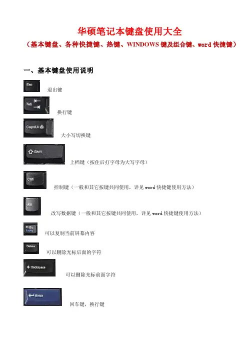
华硕笔记本键盘使用大全(基本键盘、各种快捷键、热键、WINDOWS键及组合键、word快捷键)一、基本键盘使用说明退出键换行键大小写切换键上档键(按住后打字母为大写字母)控制键(一般和其它按键共同使用,详见word快捷键使用方法)改写数据键(一般和其它按键共同使用,详见word快捷键使用方法)可以复制当前屏幕内容可以删除光标后面的字符可以删除光标前面字符回车键,换行键翻页键,可以用于部分软件尤其图片查看软件翻页二、常见键、组合键用法:F1显示当前程序或者windows的帮助内容。
F2当你选中一个文件的话,这意味着“重命名”F3当你在桌面上的时候是打开“查找:所有文件”对话框F10或ALT激活当前程序的菜单栏windows键或CTRL+ESC打开开始菜单CTRL+ALT+DELETE在win9x中打开关闭程序对话框DELETE删除被选择的选择项目,如果是文件,将被放入回收站SHIFT+DELETE删除被选择的选择项目,如果是文件,将被直接删除而不是放入回收站CTRL+N新建一个新的文件CTRL+O打开“打开文件”对话框CTRL+P打开“打印”对话框CTRL+S保存当前操作的文件CTRL+X剪切被选择的项目到剪贴板CTRL+INSERT 或CTRL+C复制被选择的项目到剪贴板SHIFT+INSERT 或CTRL+V粘贴剪贴板中的内容到当前位置ALT+BACKSPACE 或CTRL+Z 撤销上一步的操作ALT+SHIFT+BACKSPACE重做上一步被撤销的操作Windows键+M最小化所有被打开的窗口。
Windows键+CTRL+M重新将恢复上一项操作前窗口的大小和位置Windows键+E打开资源管理器Windows键+F打开“查找:所有文件”对话框Windows键+R打开“运行”对话框Windows键+BREAK打开“系统属性”对话框Windows键+CTRL+F打开“查找:计算机”对话框SHIFT+F10或鼠标右击打开当前活动项目的快捷菜单SHIFT在放入CD的时候按下不放,可以跳过自动播放CD。
笔记本说明书目录1.产品概述2.技术规格3.使用方法4.维护保养5.常见问题解答1. 产品概述笔记本电脑是一种便携式的个人计算机。
它集中了台式电脑的主要功能,并具备了移动性和便捷性。
笔记本电脑的主要组件包括显示屏、键盘、鼠标、内存、硬盘和电池。
本说明书将详细介绍笔记本电脑的技术规格、使用方法、维护保养以及常见问题解答。
2. 技术规格•处理器:Intel Core i5 1.6GHz•内存:8GB DDR4 RAM•硬盘:256GB 固态硬盘•显示屏:13.3英寸 Retina 显示屏•显卡:Intel UHD Graphics 617•操作系统:macOS Mojave•无线连接:Wi-Fi 802.11ac, 蓝牙 4.2•接口:2 个 USB-C 接口,1 个耳机插孔3. 使用方法3.1 开机和关机•开机:按下电源按钮,等待电脑启动。
•关机:点击屏幕左上角的苹果图标,选择“关机”选项。
3.2 登录和注销用户•登录用户:在开机后,输入账户名和密码,点击“登录”按钮。
•注销用户:点击屏幕左上角的苹果图标,选择“注销”选项。
3.3 使用桌面和应用程序•桌面:在登录后,你将看到一个漂亮的桌面背景图片。
桌面上可以放置应用程序快捷方式、文件和文件夹。
•应用程序:点击底部的Dock栏图标,打开已安装的应用程序。
3.4 联网和使用浏览器•Wi-Fi 连接:点击屏幕顶部的Wi-Fi图标,选择一个可用的Wi-Fi网络,并输入密码进行连接。
•使用浏览器:打开Safari浏览器,输入网址,访问网页。
3.5 文件管理和存储•文件管理:使用“Finder”应用程序可以管理和浏览文件和文件夹。
•存储:笔记本电脑配备了大容量的固态硬盘,可用于存储文件和应用程序。
4. 维护保养为了确保笔记本电脑的正常运行和延长使用寿命,请遵循以下维护保养建议:•定期清理键盘和屏幕:使用柔软的纤维布轻轻擦拭键盘和显示屏,避免使用含有酒精的清洁剂。
Version 1.1 September 2002Technical SpecificationsE U R O R A C KU B 2222F X -P RO2EURORACK UB2222FX -PROUB2222FX -PROEURORACKUltra low-noise design 22-input 2/2-bus mic/line mixer with premium mic preamplifiers and 24-bit multi-FX processors Ultra low-noise ULN design, highest possible headroom, ultra-transparent audio s 8 new state-of-the-art, studio-grade IMP Invisible Mic Preamps with:130 dB dynamic range for 24-bit, 192 kHz sampling rate inputsUltra-wide 60 dB gain rangeLowest possible distortion 0.0007% (20 Hz - 20 kHz)s Integrated 24-bit digital stereo FX processor with 99 great-sounding VIRTUALIZER presets including reverb,delay, chorus, compressor, tube distortion, vinylizer and more plus 1 kHz test tone generators Effective, extremely musical 3-band EQ with semi-parametric mid band plus switchable low-cut filter on all mono channels s Inserts on each mono channel for flexible connection of outboard equipments 16 balanced high-headroom line inputs with +4/-10 level selection on stereo channelss State-of-the-art 4580 operational amplifiers provide lowest noise and distortion better than 4560 op ampss 3 aux sends per channel: 1 pre fader for monitoring, 1 pre/post fader switchable for monitoring/FX applications,1 post fader (for internal FX or as external send)s Peak LEDs, mute, main mix and subgroup routing switches, solo and PFL functions on all channels s 2 subgroups with separate outputs for added routing flexibility s 3 multi-functional stereo aux returns with flexible routings Balanced main mix outputs with TRS and gold-plated XLR connectors, separate control room, headphones and stereo tape outputs s Control room/phones outputs with multi-input source matrixs Tape inputs assignable to main mix or control room/phones outputs s Switchable +48 V phantom power for condenser microphoness Long-wearing 60 mm logarithmic-taper ALPS ® faders and sealed rotary controlss Internal switch-mode power supply for maximum flexibility (100 - 240 V~), noise-free audio, superior transient response plus lowest possible power consumption for energy saving s Extremely rugged steel construction ensures long life even under the most demanding conditions s Rack mount brackets includeds Manufactured under ISO9000 certified management systemBLOCKDIAGRAM3SPECIFICATIONSMicrophone inputs (IMP Invisible Mic Preamp)Type XLR, electronically balanced,discrete input circuitMic E.I.N. (20 Hz - 20 kHz)@ 0 Ω source resistance-134 dB / 135.7 dB A-weighted @ 50 Ω source resistance-131 dB / 133.3 dB A-weighted @ 150 Ω source resistance-129 dB / 130.5 dB A-weightedFrequency response<10 Hz - 150 kHz (-1 dB),<10 Hz - 200 kHz (-3 dB) Gain range+10 to +60 dBMax. input level+12 dBu @ +10 dB Gain Impedance approx. 2.6 kΩ balanced Signal-to-noise ratio110 dB / 112 dB A-weighted(0 dBu In @ +22 dB gain) Distortion (THD+N)0.005% / 0.004% A-weightedLine inputType1/4" TRS connectorelectronically balanced Impedance approx. 20 kΩ balanced10 kΩ unbalancedGain range-10 to +40 dBMax. input level30 dBuFade-out attenuation1(Crosstalk attenuation)Main fader closed90 dBChannel muted89 dBChannel fader closed89 dBFrequency responseMicrophone input to main out<10 Hz - 90 kHz+0 dB / -1 dB<10 Hz - 160 kHz+0 dB / -3 dBStereo inputsType1/4" TRS connector,electronically balanced Impedance approx. 20 kΩMax. input level+22 dBuEQ mono channelsL o w80 Hz / ±15 dBMid100 Hz - 8 kHz/ ±15 dBHigh12 kHz/ ±15 dBEQ stereo channelsL o w80 Hz /±15 dBLow Mid500 Hz / ±15 dBHigh Mid 3 kHz / ±15 dBHigh12 kHz / ±15 dBAux sendsType1/4" TS connector, unbalanced Impedance approx. 120 ΩMax. output level+22 dBuStereo aux returnsType1/4" TRS connector,electronically balanced Impedance approx. 20 kΩ bal. / 10 kΩ unbal. Max. input level+22 dBu Main outputsType XLR, electronically balancedand 1/4" TRS balanced Impedance approx. 240 Ω balanced /120 Ω unbalancedMax. output level+28 dBuControl room outputsType1/4" TS connector unbalanced Impedance approx. 120 ΩMax. output level+22 dBuHeadphones outputsType1/4" TRS connector, unbalanced Max. output level+19 dBu / 150 Ω (+25 dBm)DSP24-bit Texas Instruments TM Converter24-bit Sigma-Delta,64/128-times oversampling Sampling rate46,875 kHzMain mix system data2NoiseMain mix @ -o o,Channel fader -o o-101 dBMain mix @ 0 dB,Channel fader -o o-93 dBMain mix @ 0 dB,Channel fader @ 0 dB-81 dBPower supplyPower consumption46 WFuse100 - 240 V ~: T 1.6 A H Mains connection Standard IEC receptaclePhysical/weightDimensions (H x W x D)approx. 3 7/8" (97 mm) x 16 1/16"(408 mm) x 14 1/16" (367 mm) Weight (net)approx. 4.8 kgMeasuring conditions:1: 1 kHz rel. to 0 dBu; 20 Hz - 20 kHz; line input; main output; unity gain.2:20 Hz - 20kHz; measured at main output. Channels 1 - 4 unity gain; EQ flat; all channels on main mix; channels 1/3 as far left as possible, channels 2/4 as farright as possible. Reference = +6 dBu.BEHRINGER is constantly striving to manintain the highest professional standards. As a result of these efforts, modifications may be made from time to time to existing products without prior notice. Specifications and appearance may differ from those listed or illustrated.4The information contained in this manual is subject to change without notice. No part of this manual may be reproduced or transmitted in any form or by any means, electronic or mechanical, including photocopying and recording of any kind, for any purpose, without the express writtenpermission of BEHRINGER Spezielle Studiotechnik GmbH.BEHRINGER, EURORACK, VIRTUALIZER, POWERPLAY and ULTRALINK are registered trademarks. ALL RIGHTS RESERVED.TEXAS INSTRUMENTS is a registered trademark of T exas Instruments Incorporated,which is in no way associated or affiliated with BEHRINGER. © 2002 BEHRINGER Spezielle Studiotechnik GmbH.BEHRINGER Spezielle Studiotechnik GmbH, Hanns-Martin-Schleyer-Str. 36-38, 47877 Willich-Münchheide II, GermanyT el. +49 (0) 21 54 / 92 06-0, Fax +49 (0) 21 54 / 92 06-305。