华硕N53sv笔记本说明书
- 格式:pdf
- 大小:5.05 MB
- 文档页数:71

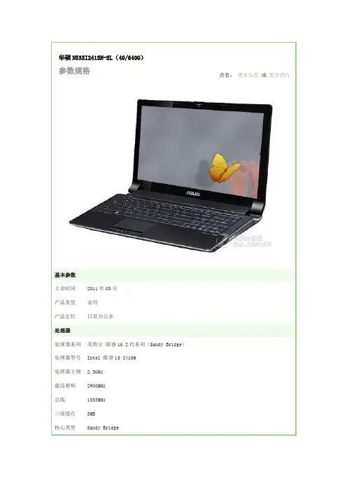
华硕N53XI241SN-SL(4G/640G)参数规格查看:更多信息或更多图片基本参数上市时间2011年03月产品类型家用产品定位日常办公本处理器处理器系列英特尔酷睿i5 2代系列(Sandy Bridge)处理器型号Intel 酷睿i5 2410M处理器主频 2.3GHz最高睿频2900MHz总线1333MHz三级缓存3MB核心类型Sandy Bridge核心数/线程双核心/四线程制程工艺32nm指令集AVX,64bit功耗35W存储设备内存容量4GB内存类型DDR3 1333MHz最大支持内8GB存硬盘容量640GB硬盘描述SATA光驱类型DVD刻录机设计类型光驱内置光驱描述支持DVD SuperMulti双层刻录显示屏屏幕尺寸15英寸屏幕比例16:9屏幕分辨率1366×768背光技术LED背光显卡显卡类型中高端独立显卡显卡芯片NVIDIA GeForce GT 550M显存容量2GB显存类型GDDR3显存位宽128bit流处理器个96数音频音频系统内置立体声音效芯片扬声器立体声扬声器麦克风内置麦克风摄像头/网络通信摄像头集成摄像头无线网卡支持802.11b/g/n无线协议网卡描述1000Mbps以太网卡接口数据接口2×USB2.0+1×USB3.0,e-SATA接口视频接口VGA,HDMI音频接口耳机输出接口,麦克风输入接口其它接口RJ45(网络接口),电源接口读卡器5合1读卡器(SD,MMC,MS,MS-Pro,MS-Duo)输入设备指取设备触摸板电源描述电池类型6芯锂电池续航时间具体时间视使用环境而定电源适配器100V-240V 90W 自适应交流电源适配器外观笔记本重量 2.71Kg外形尺寸391×266×30.5-40.5mm外壳材质复合材质外壳描述银灰色其他附带软件随机软件笔记本附件包装清单笔记本主机 x1 电池 x1电源适配器 x1 说明书 x1保修卡 x1保修信息保修政策全球联保质保时间2年质保备注2年全球联保,1年电池保修(需产品注册)客服电话400-600-6655电话备注24小时电话服务详细内容华硕笔记本电脑自用户购买之日起2年内,于正常操作使用状况下主机发生硬件故障可享受免费售后维修服务。

Important NoticesImproper handling of a vehicle , especially while raised and supported by jack stands, ramps or other mechanical means, can cause serious bodily injury or even death. It is strongly rec-ommended that a trained, experienced mechanic, with proper equipment, do the installation.The seller nor the manufacturer assumes no liability, expressed or implied, for the improper installation or use of this product or its components. Before using, the user shall determine the suitability of the products for it’s intended use. The user assume all responsibility and risk in connection there within.It is the buyer’s responsibility to have all suspension, drivetrain, steering, and other compo-nents checked for proper tightness and torque after the fi rst 100 miles and every 3,000 miles by a qualifi ed professional mechanic.Extreme care should be taken while operating your vehicle to prevent vehicle rollover or loss of control. Both can result in serious injury or death. Do not add or modify parts to this kit or use outside it’s intended purpose. Follow all safety regulations and warnings per state and federal laws.Note: Final fi tment of the wheel to caliper is the responsibility of the customer.Note: It is important to read and understand this ENTIRE installation manual, before starting the installation.Kit Contents1 Pair of calipers w/pads2 Rotors2 Retaining plate2 Preload spacers (C-clip applications)4 Caliper bolts8 T-bolts8 Nuts2 Disc brake mounting plate assembly (1 Left and 1 Right)1 stainless steel brake line kitTools and Equipment That May Be RequiredDifferent models and years of vehicle use different-sized fasteners, and every effort has been taken to correctly identify the proper sized tool for each step of the installation. Occasionally, however, manufacturers use alternate fasteners, so it’s advisable to check that each tool cor-rectly fi ts the fastener before loosening or tightening it. The following tools and equipment may be needed:9/16” socket wrench12mm socket14mm wrenchTorque wrenches capable of 10-148 lb-ft settingsSeveral ragsSmall funnel or suitable means of fi lling master cylinder reservoirBrake bleed bottle1 pair of jack stands or other means of supporting vehicleHydraulic pressPair of PliersStep 1-Remove WheelsWARNING - Brake fl uid will damage most painted surfaces. Immediately clean spilled brake fl uid from any painted surfaces. Be sure the cap is securely installed on the master cylinder. If the cap is loose or removed, it is likely more fl uid willdrip.Note: All Photographs Show Left Side Installation, unless noted otherwise.Break loose the lug nuts on both rear wheels before jacking up the car.Refer to the Owners Manual for the correct location when jacking up the vehicle. Jack up the vehicle and secure on a pair of jack stands. Never leave any vehicle supported with only a jack - always use jack-stands.After securing the vehicle at a convenient height, remove the rear wheels.Note: If you remove the bottom lug nut last while holding the bottom of the tire, it will lessen the chances of the wheel tilting on it’s own and make removal easier.Step 2 -Removal of Drum Brakes and AxleRemove brake drums from thebrake assembly.Remove the hard line from thewheel cylinder attached to thebacking plate.For c-clip applications- Removethe differential cover, unbolt thecross shaft and remove it from thevehicle. See factory service manualfor additional information.Using a 9/16” socket, remove thefour nuts that hold each axle shaftinto the axle and remove the axleshafts from the axle. Some leakagemay occur.Remove the backing plate from theaxle housing.Wipe clean grease and contami-nants from all surfaces.For semi-fl oat applications- Pressthe old bearings and seals fromthe axle shafts. C-clip applicationsdo not need the removal of the oldbearings and seals unless parts areneeded to be replaced.Install the disc brake mounting plate onto the axle flange with new supplied retaining bolts. The mounting plate is directional, insurethat the plate is installed on the correct side.Step 3 -Install Disc Mounting PlateIn order to install this kit, remove the factory bolts from the axle fl ange. If installing on a C-clip application do not remove the fac-tory bolts.Install the supplied bolts (longer than factory bolts) in the axle fl ange.Adjust the internal parking brake shoes with the adjuster until there is just enough room to slide the ro-tor over the shoes. Refer to the fac-tory service manual for additional information.STEP 4 -Install Axle ShaftsApply grease to the outside of the bearing seal assembly and slide the preload spacer onto the seal. The grease will help hold the spacer in place.Slide the axle shaft into the axle housing by hand, lining it up with the differential. The axle shaft should not be forced, damage mayoccur.On C-clip retained axles, slide the axles all the way into the axle hous-ing using care to avoid damage to the splines or the bearing surface. Reinstall the C-clip and the cross shaft. Ensure that all old silicone is cleaned from the differential hous-ing and the differential cover, and reinstall the differential cover using a new gasket or silicone. Fill thehousing with new oil.Using a hydraulic press, press the new bearing and retaining collar onto the axle shaft. Refer to the factory service manual for more details.Grease the shaft where the axle shaft seal will be installed, theninstall the seal.Install the retaining plate and new preload spacer on axle shaft. Notice the direction the preload spacer is facing in the photo to the right. The chamfer side faces inboard.STEP 5 -Install the Rotor and CaliperInstall the rotor on the axle.Install the brake pads in the caliper.Using a 12mm socket wrench in-stall the caliper onto the mounting plate. Torque the bolts to 15-18 ft-lbs.Line up the access holes located on the axle shafts with the retainer bolts. Using a 9/16” socket wrench tighten the four nuts to 25 - 30 ft-lbs.STEP 4 -(Continued)Install Axle ShaftsSTEP 6 -Install Stainless Steel Brake LinesInstall the caliper end of the stainless steel brake line by fi rst placing a copper crush washer on either side of the banjo fi tting.Insert the banjo bolt into the caliper using a 14mm wrench or socket to tighten it. Insert the stainless steel brake line fi tting through the chassis bracket, and screw it onto the hard line fi tting by hand a few turns, to ensure that it is properly engaged. Tighten the hard line fi tting.Check to ensure that the brake line is not binding in any way, nor interfering with any suspension component.Note that you will need to purchase shorter metal brake lines from an automotive pats supplier.If the brake line is not properly routed, a catastrophic failure could occur. If you are unsure that the line is routed properly and safely, do not drive the car. Please call our Tech Support Dept. for assistance if you have any doubt as to the brake line routing.Install the emergency brake cable at the mounting plate and adjust, refer to the factory service manual.If realignment is necessary, loosen the banjo bolt, and realign the brake line, or loosen the inboard end of the line, and slightly re-clock the fitting.Weld the brake line mounting tab onto the axle tube. Install the brake line through the tab and install the c-clip to secure the line.STEP 7-Bleed BrakesComplete installation on both sides of the vehicle before bleeding the system. Note: The calipers and lines will need to fi ll with fl uid, quickly draining the master cylinder reservoir. Keep a close watch on the fl uid level when initially bleeding the system. Do not allow the master cylinder reservoir to run dry and draw in air. Doing so may require the brake system to be serviced by a certifi ed brake technician.Refer to owners manual for torque used on bleed screws.After initially bleeding the system, gently tap the caliper body with a non-marring mallet or hammer to dislodge any small air bubbles and re-bleed.After bleeding, apply a constant pressure to the brake pedal and check all connections, including bleed screws, and both ends of the line for leaks.Brake fl uid will damage most painted surfaces. Immediately clean spilled brake fl uid from any painted surface, including the caliper. Though caliper paint is designed to resist harsh chemicals, prolonged exposure will damage the fi nish.STEP 8-Reinstall wheelsCheck wheel to caliper clearance before installing wheels!Reinstall the wheels and torque the lug nuts to your wheel manufacturer’s specifi cations. It may be necessary to snug the bolts before lowering the vehicle and then torque the wheels when the car is on the ground. Alternatively, an assistant may depress the brake pedal while you tighten the wheel nuts to the proper torque setting.Carefully test-drive the vehicle in a safe area at low speed to insure all components are working correctly.。
1、启动阶段1)红灯每2秒闪一次,且伴为“哔-,哔-”警示音:电调未检测到油门信号。
2)绿灯闪烁N次:上电时自动进行锂电节数检测,闪烁N次表示当前锂电为N节。
2、行驶阶段1)油门摇杆处于中点区域,红色和绿色LED均熄灭。
2)前进时,红色LED恒亮;当油门处于正向最大(100%油门)时,绿色LED也会点亮。
3)倒退时,红色LED恒亮。
3、相关保护功能触发时,LED状态含义:1)红灯持续闪烁(单闪,“☆,☆,☆”方式闪烁):电池电压太低,电调进入电池低压保护状态。
2)绿灯持续闪烁(单闪,“☆,☆,☆”方式闪烁):电调温度过高,电调进入过热保护状态。
故障现象解决方法可能原因1、电池电压没有输入到电调;1、检查电池与电调是否连接可靠,如有焊接不良,请重新焊好;上电后电机无鸣音,指示灯也未闪亮06编程设定说明08电调状态指示灯(LED)说明09保护功能说明10故障快速处理01声明Seaking Pro 120A • Seaking Pro 160A船用无刷电子调速器使用说明书· 调试请将船模架起,确保船桨不会碰到人或其他物体,以免发生安全事故。
03产品特色· 轻量化设计,适合竞赛要求。
· 出色的防水性能(160A电调采用塑封工艺,120A电调采用纳米镀膜工艺),一般情况下无需做防水处理即可直接使用(注:使用后请将电调插头吹干,以免锈蚀)。
· 内置超强开关模式BEC,持续电流达到4A,瞬间达到8A,且支持 6V和7.4V 切换,轻松驱动各种强力舵机及高压舵机。
· 采用好盈专利铜片导热技术,配合水冷模块和极低热阻的内部MOSFET,使得电调的耐流能力及可靠性大大增强。
· 使用顶级竞赛核心程序,具有一流的操控手感及丰富的调节选项,适应各种比赛环境。
· 行业首创的超速功能(即:开启Turbo进角),让马达瞬间释放更强动力,轻松超越竞争对手。
华硕N53SV拆机,改造,升级全攻略前后一个月,LZ对手上的华硕N53SV-XE进行了全方位的改造升级,基本上除了没有动主板,改模具,能升级改造的,都自己DIY了,现在就把这一个月以来的经验与大家分享下。
一.前言手上的机器型号为N53SV-XE1,今年三月购于美国亚马逊。
LZ身在美国,因此改装配件入手的手段与国内的朋友们或许不同,但大部分东西都是可以在淘宝上找到的。
不同型号的N53可能在硬件配置甚至是模具上有所不同,因此对于不同型号的机器的拆机改造,此教程仅作参考,如果对不同型号的机器强行依葫芦画瓢,以致产生杯具,LZ恕不负责。
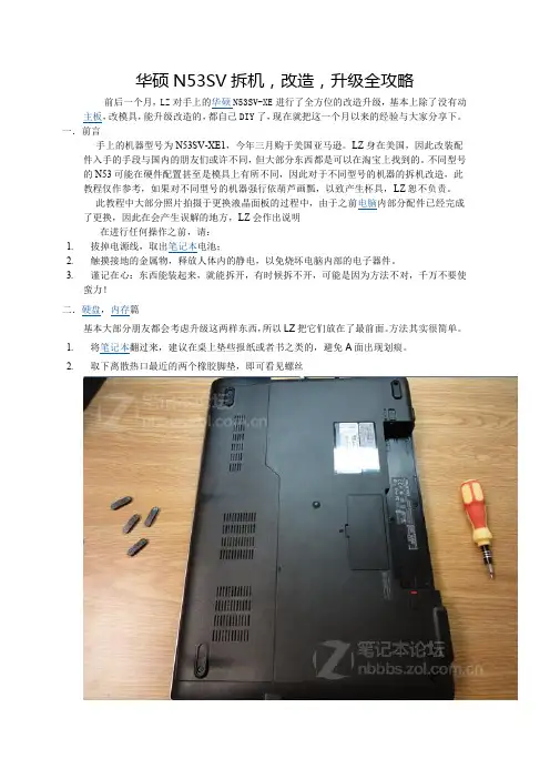
此教程中大部分照片拍摄于更换液晶面板的过程中,由于之前电脑内部分配件已经完成了更换,因此在会产生误解的地方,LZ会作出说明在进行任何操作之前,请:1. 拔掉电源线,取出笔记本电池;2. 触摸接地的金属物,释放人体内的静电,以免烧坏电脑内部的电子器件。
3. 谨记在心:东西能装起来,就能拆开,有时候拆不开,可能是因为方法不对,千万不要使蛮力!二.硬盘,内存篇基本大部分朋友都会考虑升级这两样东西,所以LZ把它们放在了最前面。
方法其实很简单。
1. 将笔记本翻过来,建议在桌上垫些报纸或者书之类的,避免A面出现划痕。
2. 取下离散热口最近的两个橡胶脚垫,即可看见螺丝3. 卸下螺丝后横向将挡板抽出,即可见硬盘区与内存区。
4. 卸下固定硬盘架的三根螺丝,拉动黑条将硬盘单元抽出。
5. 卸下固定硬盘的四颗螺丝,成功取下硬盘。
(LZ的原装硬盘是希捷的500GB,7200转,是不是混合硬盘不清楚,此刻躺在光驱位的硬盘架里)三.更换巧克力键盘篇(非背光)LZ最先萌生“换意”的就是键盘,因为这个键盘实在是太让人蛋疼了!用惯了巧克力键盘,在N53上经常打错,已经到了影响工作效率的地步!怎么办?换掉!LZ的键盘也是在ebay上搜到的。
其实换键盘不难,但关键在于要买对!如果发现模具不一样,再好的键盘也没法用。
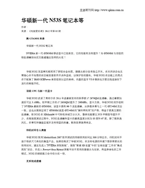
华硕新一代N53S笔记本等作者:来源:《电脑爱好者》2012年第05期携GT630M来袭华硕新一代N53S笔记本NVIDIA新一代GT630M移动显卡已经面世,它的性能有没有提升?当GT630M与顶级四核处理器结合后又能碰撞出怎样的火花?华硕N53S顶盖掌托都采用了镁铝合金材质,摄像头部分设有独立开关,在关闭状态也无需担心在不知情的状态被恶意软件开启和监视,以保护你的隐私。
华硕N53S在功能上的亮点在于配备了B&O ICEPower音效级别认证的音响,内置的蓝牙V3.0模块也方便无线连接时下流行的智能手机。
顶级CPU与新一代显卡华硕N53S武装了英特尔在2011年底最新发布的秋季款i7-2670QM处理器,通过睿频加速后可达3.1GHz,较早期上市的i7-2630QM提升了200MHz。
显卡方面,华硕N53S则升级到了NVIDIA最新的GT630M,该显卡拥有96个流处理器,从参数来看与上一代GT540M完全一致,这也从侧面证明了GT630M就是GT540M的“循环再利用”的产物。
得益于更高主频的处理器,使N53S在3DMark06中可轻松突破万分大关,整体性能要比N53早期型号提升不少。
在高强度测试过程中,N53S处理器和显卡的最高温度分别为83度和67度,除了散热通风孔,在掌托和键盘区域并没有明显的热量,散热效果值得肯定。
待机时间令人满意华硕N53S使用MoblieMark 2007软件测试的持续使用时间达300分钟左右,待机时间不逊于很多尺寸类似的集显产品。
如果你购买了华硕N53S,在没有电源的环境下想获得更长的使用时间,建议先进入“NVID IA控制面板”,强制“管理3D设置”中的“全局设置”工作在“集成图形”状态,并进入Power4 Gear Hybrid屏蔽平时不常用的摄像头与光驱,再选择省电的工作模式,N53S的续航能力会令你大吃一惊。
无系统成遗憾可能是出于成本的考虑,这款N53S随机并没有预装操作系统,购买后需要用户自行安装。
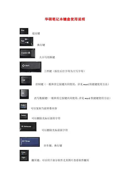
华硕笔记本键盘使用说明退出键换行键大小写切换键上档键(按住后打字母为大写字母)控制键(一般和其它按键共同使用,详见word快捷键使用方法)改写数据键(一般和其它按键共同使用,详见word快捷键使用方法)可以复制当前屏幕内容可以删除光标后面的字符可以删除光标前面字符回车键,换行键翻页键,可以用于部分软件尤其图片查看软件翻页FN+F1:降低屏幕亮度FN+F2:升高屏幕亮度FN+F3:等待状态FN+F4:休眠状态FN+F5:降低音量FN+F6:增加音量FN+F7:静音FN+F10:切换显示器FN+F11:等于按下NUM LOCK键FN+F12:等于按下Scroll lock键FN+Insert:等于按下打印键(PRINT SCREEN)FN+del:等于按下SysRQ键FN+向上方向键:等于按下Page Up 键FN+向下方向键:等于按下Page Down 键FN+向左方向键:等于按下Page Home键FN+向右方向键:等于按下Page End键FN+T:拉伸屏幕下面为以前的机型S8200快捷键比较简单,大家可以对比一下FN+F5:增加亮度FN+F6:减低亮度FN+F7:关闭/打开屏幕FN+F8:前换显示器FN+F9:静音FN+F10:增加音量FN+F11:减少音量FN+F12:等于按下PAUSE间FN+insert:等于按下num lock键FN+del:等于按下Scr Lock键华硕X80系列及华硕F8系列组合键Fn + F1 进入待机或休眠模式Fn + F2 开启内置无线网络功能(视选购机型而不同)Fn + F3 E-mail快捷键,开启互联网邮件程序Fn + F4 因特网快捷键,立即开启互联网浏览器Fn + F5 调暗液晶显示屏亮度Fn + F6 调亮液晶显示屏亮度Fn + F7 液晶屏背光光源开关Fn + F8 切换液晶显示屏显示,外接显示器或电视Fn + F9 触摸板锁定快捷键,可以锁定触摸板功能Fn + F10 静音开关(仅适用于WINDOWS系统下)Fn + F11 降低音量(仅适用于WINDOWS系统下)Fn + F12 提高音量(仅适用于WINDOWS系统下)Fn + Ins 开启或关闭数字键盘功能Fn + <空格键> 等同于性能设置快捷键,按下后可设置系统性能与省电之间的关系Fn + C 此组合键可切换屏幕至不同的颜色设置选项,在屏幕画面左上方将出现一些画面Fn + V 此组合键可以开启摄像头程序Fn + T 此组合键可开启Power for phone程序(附)word快捷键使用方法。

Customer Self Repair (CSR)Maintenance and ServiceGuideFirst Edition /September 2021COPYRIGHT INFORMATIONNo part of this manual, including the products and software described in it, may be reproduced,transmitted, transcribed, stored in a retrieval system, or translated into any language in any form or by any means, except documentation kept by the purchaser for backup purposes, without the express written permission of ASUSTeK COMPUTER INC.(“ASUS”).ASUS PROVIDES THIS MANUAL “AS IS” WITHOUT WARRANTY OF ANY KIND, EITHER EXPRESS OR IMPLIED,INCLUDING BUT NOT LIMITED TO THE IMPLIED WARRANTIES OR CONDITIONS OF MERCHANTABILITY OR FITNESS FOR A PARTICULAR PURPOSE. IN NO EVENT SHALL ASUS, ITS DIRECTORS, OFFICERS, EMPLOYEES OR AGENTS BE LIABLE FOR ANY INDIRECT, SPECIAL, INCIDENTAL, OR CONSEQUENTIAL DAMAGES(INCLUDING DAMAGES FOR LOSS OF PROFITS, LOSS OF BUSINESS, LOSS OF USE OR DATA, INTERRUPTION OF BUSINESS AND THE LIKE), EVEN IF ASUS HAS BEEN ADVISED OF THE POSSIBILITY OF SUCH DAMAGES ARISING FROM ANY DEFECT OR ERROR IN THIS MANUAL OR PRODUCT.Products and corporate names appearing in this manual may or may not be registered trademarks or copyrights of their respective companies, and are used only for identification or explanation and to the owners’ benefit, without intent to infringe.SPECIFICATIONS AND INFORMATION CONTAINED IN THIS MANUAL ARE FURNISHED FOR INFORMATIONAL USE ONLY, AND ARE SUBJECT TO CHANGE AT ANY TIME WITHOUT NOTICE, AND SHOULD NOT BE CONSTRUED AS A COMMITMENT BY ASUS. ASUS ASSUMES NO RESPONSIBILITY OR LIABILITY FOR ANY ERRORS OR INACCURACIES THAT MAY APPEAR IN THIS MANUAL, INCLUDING THE PRODUCTS AND SOFTWARE DESCRIBED IN IT.Copyright © 2020 ASUSTeK COMPUTER INC. All Rights Reserved.LIMITATION OF LIABILITYCircumstances may arise where because of a default on ASUS’ part or other liability, you are entitled to recover damages from ASUS. In each such instance, regardless of the basis on which you are entitled to claim damages from ASUS, ASUS is liable for no more than damages for bodily injury (including death) and damage to real property and tangible personal property; or any other actual and direct damages resulted from omission or failure of performing legal duties under this Warranty Statement, up to the listed contract price of each product.ASUS will only be responsible for or indemnify you for loss, damages or claims based in contract, tort or infringement under this Warranty Statement.This limit also applies to ASUS’ suppliers and its reseller. It is the maximum for which ASUS, its suppliers, and your reseller are collectively responsible.UNDER NO CIRCUMSTANCES IS ASUS LIABLE FOR ANY OF THE FOLLOWING: (1) THIRD-PARTY CLAIMS AGAINST YOU FOR DAMAGES; (2) LOSS OF, OR DAMAGE TO, YOUR RECORDS OR DATA; OR (3) SPECIAL, INCIDENTAL, OR INDIRECT DAMAGES OR FOR ANY ECONOMIC CONSEQUENTIAL DAMAGES (INCLUDING LOST PROFITS OR SAVINGS), EVEN IF ASUS, ITS SUPPLIERS OR YOUR RESELLER IS INFORMED OF THEIR POSSIBILITY.SERVICE AND SUPPORTVisit our multi-language website at:https:///support/Table of Contents Disclaimer (4)Safety precautions (4)Installation tools (5)Before disassembly (5)Removing the base cover (6)Installing a RAM module (9)Installing an M.2card(SSD) (15)Installing the Hard Disk Drive(HDD) (22)DisclaimerASUS is not responsible for direct, indirect, intentional or unintentional damages resulting from improper installation and operation.Safety precautions•Keep liquids or moisture away from your Notebook PC before installing or removing any components.•Place your Notebook PC on a stable surface before installing or removing any components. •Detach the clip or flap before removing the signal cables to prevent damage.•Disconnect the power plug by pulling the plug evenly to avoid damage. Ensure to connect the signal cables in the correct orientation.•Disconnect all power cables and remove the battery pack (if applicable) before cleaning your Notebook PC with liquid detergent to avoid risk of electric shock.•Disconnect all power cables and remove the battery pack (if applicable) before installing or removing any components. Be sure to thoroughly to read and follow the instructions in the manual.•To avoid Electrostatic Discharge (ESD) damage the electric components inside your computer, before handling components, use a grounded wrist strap or touch a safely grounded object to prevent electric products damaged by the electrostatic discharge.Please refer to Electrostatic Discharge (ESD) Protection Notes.•Keep liquids or moisture away from your Notebook PC to avoid short circuiting.•Hold components by the edges to avoid touching the Integrated Circuits (ICs).•Before re-connecting the AC power, ensure all components are properly installed.•Reduce the risk of fire or explosion by avoiding incompatible power adapters or batteries. Use only certified power adapters or batteries supplied by ASUS or authorized retailers.•Ensure the correct screw models are re-installed to your Notebook PC to prevent damage. Protection of Stored DataFor Your important data, please make periodic back-up copies of all the data stored on the hard disk or other storage devices as a precaution against possible failures, alteration, or loss of the data. ASUS AND ITS AFFILIATES WILL NOT BE HELD LIABLE FOR ANY OF YOUR CONFIDENTIAL, PROPRIETARY OR PERSONAL DATA NOR ANY LOST OR CORRUPTED DATA, PROGRAMS OR SOFTWARE. IF YOUR DATA IS ALTERED OR LOST DUE TO ANY TROUBLE, FAILURE OR MALFUNCTION OF THE PRODUCT AND THE DATA CANNOT BE RECOVERED, WE SHALL NOT BE LIABLE FOR ANY DAMAGE OR LOSS TO DATA, SYSTEM, NETWORK, OR ANY OTHER DAMAGE RESULTING THEREFROM. WHEN COPYING OR TRANSFERRING YOUR DATA, PLEASE BE SURE TO CONFIRM WHETHER THE DATA HAS BEEN SUCCESSFULLY COPIED OR TRANSFERRED PRIOR TO PROVISIONING OF SERVICES BY US. WE DISCLAIM ANY LIABILITY FOR THE FAILURE TO COPY OR TRANSFER THE DATA CORRECTLY AND WILL HAVE NO LIABILITY FOR ANY ACTS OR OMISSIONS, INCLUDING NEGLIGENCE, BY ASUS OR A THIRD-PARTY SERVICE PROVIDER.Installation tools#1Before disassemblyA.Before your disassembly, we strongly recommend that youprepare a smartphone or other handheld camera. Duringdisassembly, use your camera to take photos to help youremember the order of assembly and location of parts.B.When lifting the base cover off, slowly and carefully open so theangle is as small as possible. To avoid damaging the cables,please confirm they are disconnected before opening the basecover completely.C.After you open the base cover, be sure to disconnect the batterycable first.D.When replacing components, if any materials, cables, tapes andothers were touched or moved, please return it to its originallocation before proceeding.E.Avoid using too much force when fastening screws to preventhardware damage.CDEBA Screwdriver Non-conductive pry tool Tweezers Anti-static glovesRemoving the base coverNOTE : The appearance of your Notebook PC ’s bottom view mayvary per model.A.Remove the screw(s) from the Notebook PC ’s base cover.Lefty -Loosey Righty -Tighty #1#1#1e the non-conductive pry tool to lift open the indicated area of the base cover as shown in the illustration.Disassembly steps:IMPORTANT! Avoid sliding the non-conductive pry tool along the side of your Notebook PC to prevent damage.StartStartC.Pull out the base cover and remove it completely from your Notebook PC.Installing a RAM moduleUpgrade the memory capacity of your Notebook PC by installing a RAM (Random Access Memory) module in the memory module compartment. The following steps show you how to install a RAM module into your Notebook PC:WARNING! Disconnect all the connected peripherals, any telephone or telecommunication lines and power connector (such as external power supply, battery pack, etc.) before removing the base cover.IMPORTANT! Visit an authorized service center or retailer forinformation on RAM module upgrades for your Notebook PC. Onlypurchase RAM modules from authorized retailers of this Notebook PC to ensure maximum compatibility and reliability.NOTE:•The appearance of your Notebook PC’s bottom view and RAMmodule may vary per model but the RAM module installationremains the same.•It is recommended that you install the RAM module underprofessional supervision. You may also visit an authorized servicecenter for further assistance.A.Before handling components, wear anti-static gloves to avoid damaging them due to static electricity.B.Remove the base cover.C.Disconnect the cable from the battery connector.NOTE : For more details, refer to the removing the base cover section in this manual.Disassembly steps:e the non-conductive pry tool to push iron sheet.e thenon-conductive pry tool to disconnect battery connector.Disassembly steps:1.Tear off the Acetate Cloth Tape from RAM slot.Unlock andremove the RAM module. Please keep this part, it will be reusedfor new RAM installation.2.Tear off the ABSORBER from RAM. Please keep this part, it willbe reused for new RAM installation.D.Remove the RAM module.NOTE :If there is material pasted on the RAM, when you replace RAM, please paste the material on the new RAM.(Not included specification label.)30°FGAssembly NoticeH. Paste the Acetate Cloth Tape to RAM slot.E.Paste the ABSORBER to new RAM.F. Align and insert the new RAM module at 30°into the memory slot.G.Once properly inserted, push down the RAM module until it clicks in place.I.Please follow the below steps to attach the battery connector.J. Install the base cover at a slight tilt at upper side first, and then press the upper side of base cover to fix from right to left.15~30K.Put the base cover down slowly, and then press left and right side of base cover to fix, and press lower side of base cover to fix.L. Secure the base cover in place using the screws.Lefty -Loosey Righty -Tighty #1#1#1Installing an M.2 card (SSD)Refer to the following steps when installing a compatible M.2 card (SSD) in your Notebook PC:IMPORTANT! Purchase your M.2 card from authorized retailers ofthis Notebook PC to ensure maximum compatibility and reliability.WARNING! Disconnect all the connected peripherals, any telephoneor telecommunication lines and power connector (such as externalpower supply, battery pack, etc.) before removing the base cover.NOTE:•The appearance of your Notebook PC’s bottom view and M.2 cardmay vary per model but the module installation remains the same.•It is recommended that you install the M.2 card underprofessional supervision. You may also visit an authorized servicecenter for further assistance.A.Before handling components, wear anti-static gloves to avoid damaging them due to static electricity.B.Remove the base cover.C.Disconnect the cable from the battery connector.NOTE : For more details, refer to the removing the base cover section in this manual.Disassembly steps:e the non-conductive pry tool to push iron sheet.e thenon-conductive pry tool to disconnect battery connector.Disassembly steps:1.Tear off the SSD TAPE from M.2 card (SSD).Please keep this part, itwill be reused for new SSD installation.2. Remove the screw*1pc and M.2 card (SSD).3.Tear off the two ABSORBERS from M.2 card (SSD) front and back side.Please keep these parts, it will be reused for new SSD installation.D.Remove the M.2 card (SSD).NOTE :If there is material pasted on the M.2 card (SSD), when you replace M.2 card (SSD), please paste the material on the new M.2 card (SSD).(Notincluded specification label.)Disassembly steps:4.Tear off the Thermal PAD from Motherboard.Please keep this part,it will be reused for new SSD installation.E.Paste the Thermal PAD to Motherboard.F. Paste the two ABSORBERS to new M.2 card (SSD) front and back side.G. Assembly the M.2 card (SSD).Assembly steps:1. Align and insert the new M.2 card into the module slot.2. Secure the M.2 card in place by fastening the screw.12I.Please follow the below steps to attach the battery connector.H. Paste the SSD TAPE to newM.2 card (SSD).J. Install the base cover at a slight tilt at upper side first, and then press the upper side of base cover to fix from right to left.15~30K.Put the base cover down slowly, and then press left and right side of basecover to fix, and press lower side of base cover to fix.L. Secure the base cover in place using the screws.Lefty -Loosey Righty -Tighty #1#1#1Installing the Hard Disk Drive (HDD) Refer to the following steps if you need to install a new Hard Disk Drive (HDD) to your Notebook PC:IMPORTANT! Only purchase an HDD from authorized retailers ofthis Notebook PC to ensure maximum compatibility and reliability.WARNING! Disconnect all the connected peripherals, anytelephone or telecommunication lines and power connector (suchas external power supply, battery pack, etc.) before removing thebase cover.NOTE:•The appearance of your Notebook PC’s bottom view and HDDmay vary per model but the HDD installation remains the same.•It is recommended that you replace the HDD under professionalsupervision. You may also visit an authorized service center forfurther assistance.A.Before handling components, wear anti-static gloves to avoid damaging them due to static electricity.B.Remove the base cover.C.Disconnect the cable from the battery connector.NOTE : For more details, refer to the removing the base cover section in this manual.Disassembly steps:e the non-conductive pry tool to push iron sheet.e thenon-conductive pry tool to disconnect battery connector.Disassembly steps:1.Disconnect the HDD FFC connector.2.Pull the rubber sleeve and remove the HDD.3.Remove the rubber sleeve from the HDD.Please keep this part, itwill be reused for new HDD installation.D.Remove the Hard Disk Drive (HDD).NOTE :If there is material pasted on the Hard Disk Drive (HDD), when you replace Hard Disk Drive (HDD), please paste the material on the new HardDisk Drive (HDD).(Not included specification label.)Disassembly steps:4.Tear off the AL Foil mylar from the HDD.Please keep this part, itwill be reused for new HDD installation.5.Disconnect the FFC connector from the HDD.Please keep this part, it will be reused for new HDD installation.Disassembly NoticeE.Connect the FFC connector to new HDD.F.Align and wrap the AL Foil mylar around the HDD as shown in theillustration below.G.Align and place the rubber sleeve on the HDD as shown in the illustrationbelow.H. Place the HDD in the compartment.I. Connect the cable to the motherboard, then push down the flap on theconnector to secure the cable.J. Please follow the below steps to attach the battery connector.K. Install the base cover at a slight tilt at upper side first, and then press the upper side of base cover to fix from right to left.15~30L.Put the base cover down slowly, and then press left and right side of base cover to fix, and press lower side of base cover to fix.M. Secure the base cover in place using the screws.Lefty -Loosey Righty -Tighty #1#1#1。
Ce symboleQuittez toute application active fonctionnant avec le lecteur. Cliquez surRetirez le câble USB.La radio s'a rrête dès que vous passez en mode Music.en mode Running (Course).Vérifiez l'état de connexion de votre podomètre à partir des icônes suivantes : > Podomètre actif> Podomètre inactif>Appuyez sur la touchesur la touche 4pour la rechercher en fin de liste. Menu Radio preset (Préréglages radio) Appuyez sur la toucheen mode Running (Course).Sélectionner la langue d'a ffichage du DMM* Spécifiez un ou plusieurs dossiers musicauxr*4T ransférez vos fichiers musicaux sur le lecteur à partir de DMM.*L'a ffichage varie selon l'utilisation. p r i n c i p a l R U N N I N G(l e c t e u r c o n n e c té)*L'a ffichage varie selon l'utilisation.p r i n c i p a l M U S I C(M U S I Q U E)(l e c t e u r c o n n e cU S I C(M A M U S I Q U E):affiche le contenu de vos dossiers musicaux ; cliquez surpour réduire/agrandir la fenêtre.R M U S I C(M U S I Q U E L E C T E U R):affiche le contenu de votre lecteur ; cliquez sur*L'a ffichage varie selon l'utilisation.d e sél e c t i o n e t v o l e t d e c o n t e n ue t d e sél e c t i o n:pour définir l'o rdre d'a ffichage dans le volet de contenu.e t d e c o n t e n u: affiche le contenu de M M Y M U S I C(MA MUSIQUE) ; sélectionnez un élément dans M M Y M U S I C(MA MUSIQUE), puis glissez-le vers P P L A Y E R M U S I C(MUSIQUE LECTEUR) .: pour transférer les pistes et/: vue développée ; présente le contenu intégral de l'élément. : piste/liste de lecture non présente sur le lecteur: indique la piste actuellement lue par DMM.*L'a ffichage varie selon l'utilisation.c t i o n e t t r a n s f e r tAssurez-vous que le lecteur est connecté lorsque vous démarrez DMM.Cliquez sur un élément pour le sélectionner. (par exemple. piste, artiste, album, genre,Liste de lectureCliquez sur pour copier votre sélection de l'o rdinateur vers le lecteur.*L'a ffichage varie selon l'utilisation.e r t p a r dép l a c e m e n tAssurez-vous que le lecteur est connecté lorsque vous démarrez DMM.Cliquez sur un élément pour le sélectionner (par exemple pistes, artiste, album, genre, liste de ). Faites glisser la sélection vers P P L A Y E R M U S I C(MUSIQUE LECTEUR) ou vers une liste de lecture spécifique.Cliquez sur Cliquez surFaites glisser votre sélection vers*L'a ffichage varie selon l'utilisation. Cliquez sur pour lancer ICliquez surous pouvez cliquer sur ou sur(MUSIQUE LECTEUR) est réduite, un icone intituléCliquez surffichage détaillé du contenu.Le USB ne pasAttendez que l'icôneMeet Philips & Nike on the Internettype number - psa260© 2004 Phillips, Nike, Inc. All rights reserved. 。
本人的电脑买了一年左右,从未拆开清过灰本次拆机的目的:更换内存条和硬盘清理灰尘重新涂抹导热膏首先需要的工具一个螺丝刀和被替换的硬盘和内存条! 不过好像忘了把导热膏拍进去了……请注意把拆下来的螺丝妥善分类!不要堆到一起,否则你安装的时候就该抓狂了!我的方法是找几张纸分别写上后盖,硬盘,键盘,主板……然后把螺丝放上面使用类似与我的方法的童鞋请千万小心你的螺丝……把笔记本翻过来,首先请务必拔下电源并取下电池,这一点很重要!不听劝告者……后果自负!然后拆掉所有你所能看见的螺丝,注意电池取掉后里面还会有两个螺丝!卸掉螺丝后下面的盖子轻轻向下搓一下就可以取下来了不知道的我居然把它给硬翘下来了,结果我后盖的卡扣断了两个去掉后盖的样子,继续拆螺丝,注意硬盘下面还有一个!这是你的内存条轻轻向外扣一下两边,内存条就会自动弹起,然后取下安装新内存条的时候先把内存条插进去以后轻轻向下压即可你的无线网卡如果你的电脑不内置蓝牙而你又不想让蓝牙接收器占用你一个U口的话,那就要换他了!你的硬盘拆下固定硬盘的四个螺丝,然后向后滑就可以取下硬盘了!硬盘的两边各有两个螺丝!拆掉后就可以把硬盘从铁架中取下来了,然后把新买的硬盘换上去!不过你要是想继续往下拆的话,硬盘就可以先放一边了接下来就该拆键盘了键盘上端有四个空隙,用平角螺丝刀向屏幕方向用力翘,很容易就可以把键盘翘下来了!注意不要光把键盘的塑料板翘起来了!键盘拆下来后还有一根排线没拆掉将白色部分轻轻向外扣出来一点,不要彻底扣下来,那就不是能扣下来的设定!然后就可以向后拉出排线彻底取下键盘了拆下键盘后撕开两处胶布粘住的地方,将白色扣子垂直面板方向向上抠然后拆掉你看见的所有螺丝这时候就能把光驱抽出来了这时候先不要急着翘面板把电脑翻过来光驱这里还隐藏着三个螺丝然后就可以把面板翘下来了被抽出的光驱……这就是面板被拆下来后的样子拆开的一瞬间扑了我一脸的灰,里面已经脏的一塌糊涂了……这就是为什么官网也会把A53SV检测成K53SV的原因了……请牢记这里的螺丝分布图否则等到安装的时候摔螺丝刀返工可别怪我没提醒你不要问我为什么会知道……主板左上角的这里还有几个隐藏螺丝,注意喇叭左边那个螺丝孔,千万不要在那里上个螺丝!否则我保证你摔螺丝刀!一样不要问我为什么会知道取主板之前记得这里白色的地方也要拔掉!然后把主板翻个面就行,不要强行往下取,我并没有把显示器的线拆掉那个太麻烦,而且也不取也不影响后面的操作,我就懒了一下把这几个螺丝拆下来,再把右上角那里拔出来,就可以把风扇拆下来了!我已经把螺丝拆了,不好意思!右下角的那个螺丝是用纸贴住的,质保尚未过期的童鞋请三思而后行……还有这里安装的时候切记不要玩命的上螺丝,适当就好江湖传言,用力过猛会压碎CPU,还好我没压碎~~~我的风扇积了近两毫米的灰……两毫米啊!!!原厂硅脂已经被我擦干净了……第一次涂,水平不行,莫见笑……到此为止就算是拆完了,剩下的就只有反向装回去了,如果你已经不记得拆机过程了,不妨倒着看帖子~~~~。