华硕P8H67-I DELUXE主板中文说明书
- 格式:pdf
- 大小:2.08 MB
- 文档页数:62


摘要本指南提供有关组件、计算机设置、备份等方面的信息。
法律信息©Copyright 2022 HP Development Company, L.P.AMD 是 Advanced Micro Devices, Inc. 的商标。
Linux® 是 Linus T orvalds 在美国和其他国家/地区的注册商标。
HDMI、HDMI High-Definition Multimedia Interface 和 HDMI 徽标是 HDMI Licensing LLC 的商标或注册商标。
Microsoft 和 Windows 是 Microsoft Corporation 在美国和/或其他国家/地区的注册商标或商标。
NVIDIA 是 NVIDIA Corporation 在美国和其他国家/地区的商标或注册商标。
Red Hat Enterprise Linux 是 Red Hat, Inc. 在美国和其他国家/地区的注册商标。
USB Type-C® 是 USB Implementers Forum 的注册商标。
DisplayPort™ 和 DisplayPort™ 徽标是 Video Electronics Standards Association (VESA) 在美国和其他国家/地区所有的商标。
本文所含信息如有更改,恕不另行通知。
HP 产品和服务附带的明示保修声明中阐明了此类产品和服务的全部保修服务。
本文档中的任何内容均不构成任何额外保修。
HP 对本文档中出现的技术错误、编辑错误或遗漏之处不承担任何责任。
第一版:2022 年 11 月文档部件号:N24511-AA1产品通知本指南介绍大多数产品共有的功能。
您的计算机上可能未提供某些功能。
并非所有功能在所有 Windows 版本中都可用。
系统可能需要升级和/或单独购买硬件、驱动程序、软件或 BIOS 更新,才能充分利用 Windows 功能。


Important NoticesImproper handling of a vehicle , especially while raised and supported by jack stands, ramps or other mechanical means, can cause serious bodily injury or even death. It is strongly rec-ommended that a trained, experienced mechanic, with proper equipment, do the installation.The seller nor the manufacturer assumes no liability, expressed or implied, for the improper installation or use of this product or its components. Before using, the user shall determine the suitability of the products for it’s intended use. The user assume all responsibility and risk in connection there within.It is the buyer’s responsibility to have all suspension, drivetrain, steering, and other compo-nents checked for proper tightness and torque after the fi rst 100 miles and every 3,000 miles by a qualifi ed professional mechanic.Extreme care should be taken while operating your vehicle to prevent vehicle rollover or loss of control. Both can result in serious injury or death. Do not add or modify parts to this kit or use outside it’s intended purpose. Follow all safety regulations and warnings per state and federal laws.Note: Final fi tment of the wheel to caliper is the responsibility of the customer.Note: It is important to read and understand this ENTIRE installation manual, before starting the installation.Kit Contents1 Pair of calipers w/pads2 Rotors2 Retaining plate2 Preload spacers (C-clip applications)4 Caliper bolts8 T-bolts8 Nuts2 Disc brake mounting plate assembly (1 Left and 1 Right)1 stainless steel brake line kitTools and Equipment That May Be RequiredDifferent models and years of vehicle use different-sized fasteners, and every effort has been taken to correctly identify the proper sized tool for each step of the installation. Occasionally, however, manufacturers use alternate fasteners, so it’s advisable to check that each tool cor-rectly fi ts the fastener before loosening or tightening it. The following tools and equipment may be needed:9/16” socket wrench12mm socket14mm wrenchTorque wrenches capable of 10-148 lb-ft settingsSeveral ragsSmall funnel or suitable means of fi lling master cylinder reservoirBrake bleed bottle1 pair of jack stands or other means of supporting vehicleHydraulic pressPair of PliersStep 1-Remove WheelsWARNING - Brake fl uid will damage most painted surfaces. Immediately clean spilled brake fl uid from any painted surfaces. Be sure the cap is securely installed on the master cylinder. If the cap is loose or removed, it is likely more fl uid willdrip.Note: All Photographs Show Left Side Installation, unless noted otherwise.Break loose the lug nuts on both rear wheels before jacking up the car.Refer to the Owners Manual for the correct location when jacking up the vehicle. Jack up the vehicle and secure on a pair of jack stands. Never leave any vehicle supported with only a jack - always use jack-stands.After securing the vehicle at a convenient height, remove the rear wheels.Note: If you remove the bottom lug nut last while holding the bottom of the tire, it will lessen the chances of the wheel tilting on it’s own and make removal easier.Step 2 -Removal of Drum Brakes and AxleRemove brake drums from thebrake assembly.Remove the hard line from thewheel cylinder attached to thebacking plate.For c-clip applications- Removethe differential cover, unbolt thecross shaft and remove it from thevehicle. See factory service manualfor additional information.Using a 9/16” socket, remove thefour nuts that hold each axle shaftinto the axle and remove the axleshafts from the axle. Some leakagemay occur.Remove the backing plate from theaxle housing.Wipe clean grease and contami-nants from all surfaces.For semi-fl oat applications- Pressthe old bearings and seals fromthe axle shafts. C-clip applicationsdo not need the removal of the oldbearings and seals unless parts areneeded to be replaced.Install the disc brake mounting plate onto the axle flange with new supplied retaining bolts. The mounting plate is directional, insurethat the plate is installed on the correct side.Step 3 -Install Disc Mounting PlateIn order to install this kit, remove the factory bolts from the axle fl ange. If installing on a C-clip application do not remove the fac-tory bolts.Install the supplied bolts (longer than factory bolts) in the axle fl ange.Adjust the internal parking brake shoes with the adjuster until there is just enough room to slide the ro-tor over the shoes. Refer to the fac-tory service manual for additional information.STEP 4 -Install Axle ShaftsApply grease to the outside of the bearing seal assembly and slide the preload spacer onto the seal. The grease will help hold the spacer in place.Slide the axle shaft into the axle housing by hand, lining it up with the differential. The axle shaft should not be forced, damage mayoccur.On C-clip retained axles, slide the axles all the way into the axle hous-ing using care to avoid damage to the splines or the bearing surface. Reinstall the C-clip and the cross shaft. Ensure that all old silicone is cleaned from the differential hous-ing and the differential cover, and reinstall the differential cover using a new gasket or silicone. Fill thehousing with new oil.Using a hydraulic press, press the new bearing and retaining collar onto the axle shaft. Refer to the factory service manual for more details.Grease the shaft where the axle shaft seal will be installed, theninstall the seal.Install the retaining plate and new preload spacer on axle shaft. Notice the direction the preload spacer is facing in the photo to the right. The chamfer side faces inboard.STEP 5 -Install the Rotor and CaliperInstall the rotor on the axle.Install the brake pads in the caliper.Using a 12mm socket wrench in-stall the caliper onto the mounting plate. Torque the bolts to 15-18 ft-lbs.Line up the access holes located on the axle shafts with the retainer bolts. Using a 9/16” socket wrench tighten the four nuts to 25 - 30 ft-lbs.STEP 4 -(Continued)Install Axle ShaftsSTEP 6 -Install Stainless Steel Brake LinesInstall the caliper end of the stainless steel brake line by fi rst placing a copper crush washer on either side of the banjo fi tting.Insert the banjo bolt into the caliper using a 14mm wrench or socket to tighten it. Insert the stainless steel brake line fi tting through the chassis bracket, and screw it onto the hard line fi tting by hand a few turns, to ensure that it is properly engaged. Tighten the hard line fi tting.Check to ensure that the brake line is not binding in any way, nor interfering with any suspension component.Note that you will need to purchase shorter metal brake lines from an automotive pats supplier.If the brake line is not properly routed, a catastrophic failure could occur. If you are unsure that the line is routed properly and safely, do not drive the car. Please call our Tech Support Dept. for assistance if you have any doubt as to the brake line routing.Install the emergency brake cable at the mounting plate and adjust, refer to the factory service manual.If realignment is necessary, loosen the banjo bolt, and realign the brake line, or loosen the inboard end of the line, and slightly re-clock the fitting.Weld the brake line mounting tab onto the axle tube. Install the brake line through the tab and install the c-clip to secure the line.STEP 7-Bleed BrakesComplete installation on both sides of the vehicle before bleeding the system. Note: The calipers and lines will need to fi ll with fl uid, quickly draining the master cylinder reservoir. Keep a close watch on the fl uid level when initially bleeding the system. Do not allow the master cylinder reservoir to run dry and draw in air. Doing so may require the brake system to be serviced by a certifi ed brake technician.Refer to owners manual for torque used on bleed screws.After initially bleeding the system, gently tap the caliper body with a non-marring mallet or hammer to dislodge any small air bubbles and re-bleed.After bleeding, apply a constant pressure to the brake pedal and check all connections, including bleed screws, and both ends of the line for leaks.Brake fl uid will damage most painted surfaces. Immediately clean spilled brake fl uid from any painted surface, including the caliper. Though caliper paint is designed to resist harsh chemicals, prolonged exposure will damage the fi nish.STEP 8-Reinstall wheelsCheck wheel to caliper clearance before installing wheels!Reinstall the wheels and torque the lug nuts to your wheel manufacturer’s specifi cations. It may be necessary to snug the bolts before lowering the vehicle and then torque the wheels when the car is on the ground. Alternatively, an assistant may depress the brake pedal while you tighten the wheel nuts to the proper torque setting.Carefully test-drive the vehicle in a safe area at low speed to insure all components are working correctly.。
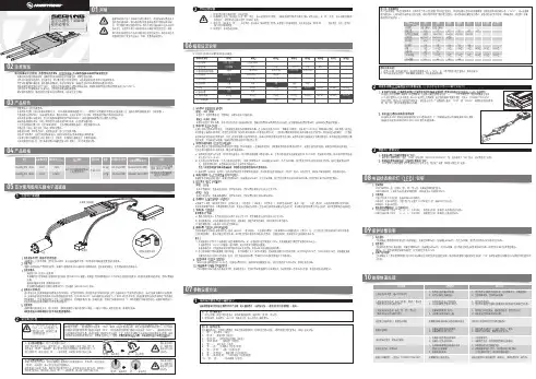
1、启动阶段1)红灯每2秒闪一次,且伴为“哔-,哔-”警示音:电调未检测到油门信号。
2)绿灯闪烁N次:上电时自动进行锂电节数检测,闪烁N次表示当前锂电为N节。
2、行驶阶段1)油门摇杆处于中点区域,红色和绿色LED均熄灭。
2)前进时,红色LED恒亮;当油门处于正向最大(100%油门)时,绿色LED也会点亮。
3)倒退时,红色LED恒亮。
3、相关保护功能触发时,LED状态含义:1)红灯持续闪烁(单闪,“☆,☆,☆”方式闪烁):电池电压太低,电调进入电池低压保护状态。
2)绿灯持续闪烁(单闪,“☆,☆,☆”方式闪烁):电调温度过高,电调进入过热保护状态。
故障现象解决方法可能原因1、电池电压没有输入到电调;1、检查电池与电调是否连接可靠,如有焊接不良,请重新焊好;上电后电机无鸣音,指示灯也未闪亮06编程设定说明08电调状态指示灯(LED)说明09保护功能说明10故障快速处理01声明Seaking Pro 120A • Seaking Pro 160A船用无刷电子调速器使用说明书· 调试请将船模架起,确保船桨不会碰到人或其他物体,以免发生安全事故。
03产品特色· 轻量化设计,适合竞赛要求。
· 出色的防水性能(160A电调采用塑封工艺,120A电调采用纳米镀膜工艺),一般情况下无需做防水处理即可直接使用(注:使用后请将电调插头吹干,以免锈蚀)。
· 内置超强开关模式BEC,持续电流达到4A,瞬间达到8A,且支持 6V和7.4V 切换,轻松驱动各种强力舵机及高压舵机。
· 采用好盈专利铜片导热技术,配合水冷模块和极低热阻的内部MOSFET,使得电调的耐流能力及可靠性大大增强。
· 使用顶级竞赛核心程序,具有一流的操控手感及丰富的调节选项,适应各种比赛环境。
· 行业首创的超速功能(即:开启Turbo进角),让马达瞬间释放更强动力,轻松超越竞争对手。
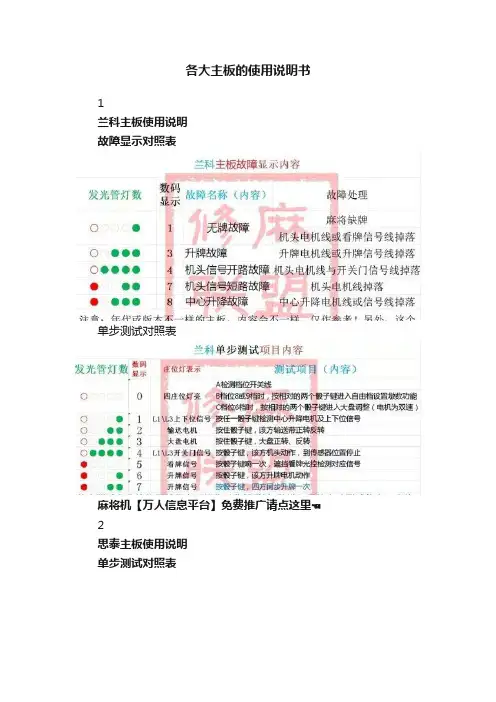
各大主板的使用说明书1兰科主板使用说明故障显示对照表单步测试对照表麻将机【万人信息平台】免费推广请点这里☜2思泰主板使用说明单步测试对照表故障显示对照表档位开关表标准档位表中01档为自由档,该档出厂时已经设置了默认的洗牌方式,也可通过如下方式进行修改:1、在休闲状态把档位码拨成“00”,进入调试模式。
2、按住面对面(比如按住“东”、“西”)的两个骰子键坚持约3秒,听到蜂鸣器长音和语音提示时释放按键,进入自由档设置模式。
同时双数码管显示“==”并停留1秒,然后可以看到双数码和连庄灯显示骰子灯长亮(闪烁则表示最后一墩牌为单张)的一方的洗牌墩数,其中休闲灯亮代表10以上数据,连庄灯显示规律与显示连庄相同,同时伴有语音提示。
3、按骰子灯不亮的一方骰子键,则首先显示该方洗牌墩数。
按骰子灯亮的一方骰子键,则该方洗牌墩数加1,加到19后变为0,在设置过程中都有语音提示最新的洗牌墩数。
重复以上操作,直到四方洗牌数都设置完成。
4、同时按住两个升降键,保存数据,并退回调试模式。
5、通过上述设置后,麻将机将永久保存该数据,除非用户再次修改。
麻将机【万人信息平台】免费推广请点这里☜3杰勋/晟廷主板使用说明故障对照表单步测试对照表档位开关表AB档位调试一、直接调试数码开关直接按拨码开关相应加减档位切换不同玩法。
(注:电子显示器要按住开关越3秒,再相应加减)二、自定义档位调试1、进入10档,按任意骰子键10秒直到蜂鸣器报警,进入自定义档位设定。
2、分别按四方骰子键,设定墩数,最大20墩。
3、墩数设定好后按任意一个升降健进行确认,自定义档位设定完毕。
三、用骰子盘调档位1、按住任意两个相邻的骰子键5秒不放开始进入开始进入电子档位调试。
进入电子档位调试复位灯是闪烁状态。
2、进入电子档位调试后,按升降健(两个升降健其中一个加,另一个减)进行档位的设定。
设置的档位会在骰子盘显示器上显示当前的档位数字。
3、档位设置完成后,按任意一个骰子键确定档位并退出,进入设置好的档位洗牌。
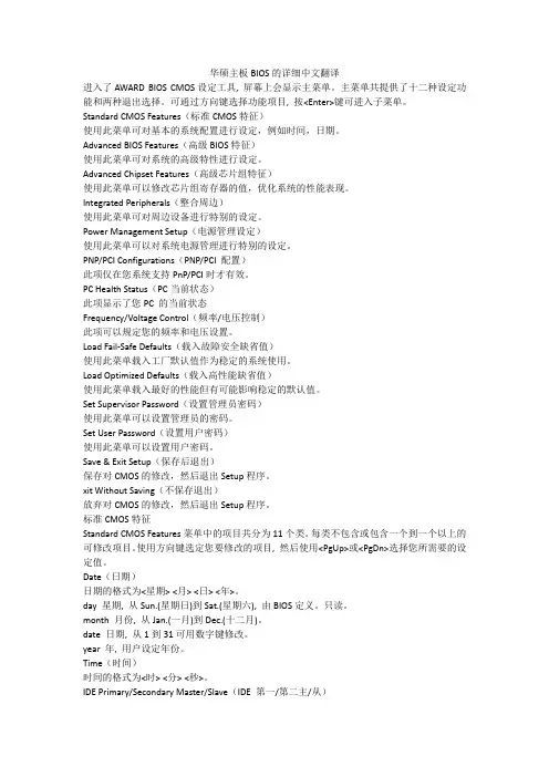
华硕主板BIOS的详细中文翻译进入了AWARD BIOS CMOS设定工具, 屏幕上会显示主菜单。
主菜单共提供了十二种设定功能和两种退出选择。
可通过方向键选择功能项目, 按<Enter>键可进入子菜单。
Standard CMOS Features(标准CMOS特征)使用此菜单可对基本的系统配置进行设定,例如时间,日期。
Advanced BIOS Features(高级BIOS特征)使用此菜单可对系统的高级特性进行设定。
Advanced Chipset Features(高级芯片组特征)使用此菜单可以修改芯片组寄存器的值,优化系统的性能表现。
Integrated Peripherals(整合周边)使用此菜单可对周边设备进行特别的设定。
Power Management Setup(电源管理设定)使用此菜单可以对系统电源管理进行特别的设定。
PNP/PCI Configurations(PNP/PCI 配置)此项仅在您系统支持PnP/PCI时才有效。
PC Health Status(PC当前状态)此项显示了您PC 的当前状态Frequency/Voltage Control(频率/电压控制)此项可以规定您的频率和电压设置。
Load Fail-Safe Defaults(载入故障安全缺省值)使用此菜单载入工厂默认值作为稳定的系统使用。
Load Optimized Defaults(载入高性能缺省值)使用此菜单载入最好的性能但有可能影响稳定的默认值。
Set Supervisor Password(设置管理员密码)使用此菜单可以设置管理员的密码。
Set User Password(设置用户密码)使用此菜单可以设置用户密码。
Save & Exit Setup(保存后退出)保存对CMOS的修改,然后退出Setup程序。
xit Without Saving(不保存退出)放弃对CMOS的修改,然后退出Setup程序。
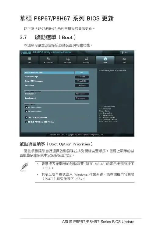
ASUS P8P67/P8H67 Series BIOS Update 華碩 P8P67/P8H67 系列 BIOS 更新以下為 P8P67/P8H67 系列主機板的資訊更新。
3.7 啟動選單(Boot)本選單可讓您改變系統啟動裝置與相關功能。
Main Ai Tweaker Advanced Monitor T oolExit Version 2.00.1201. Copyright (C) 2010 American Megatrends, Inc.Select the keyboard NumLock state →←: Select Screen ↑↓: Select Item Enter: Select +/-: Change Opt.F1: General Help F2: Previous Values F5: Optimized Defaults F10: Save ESC: Exit EFI BIOS Utility - Advanced Mode Bootup NumLock StateOn Enabled Force BIOS EZ ModeBoot Option Priorities P3: xxxxxxx P4: xxxxxxxBoot Override > P5: xxxxxxxxxxxx> P6: xxxxxxxxxxxx > Hard Drive BBS Priorities > CD/DVD ROM Drive BBS Priorities 啟動項目順序(Boot Option Priorities)這些項目讓您自行選擇啟動磁碟並排列開機裝置順序。
螢幕上顯示的裝置數量依據系統中安裝的裝置而定。
• 要選擇系統開機的啟動裝置,請在 ASUS 的圖示出現時按下<F8>。
• 若要以安全模式進入 Windows 作業系統,請在開機自我測試(POST)結束後按下 <F8>。
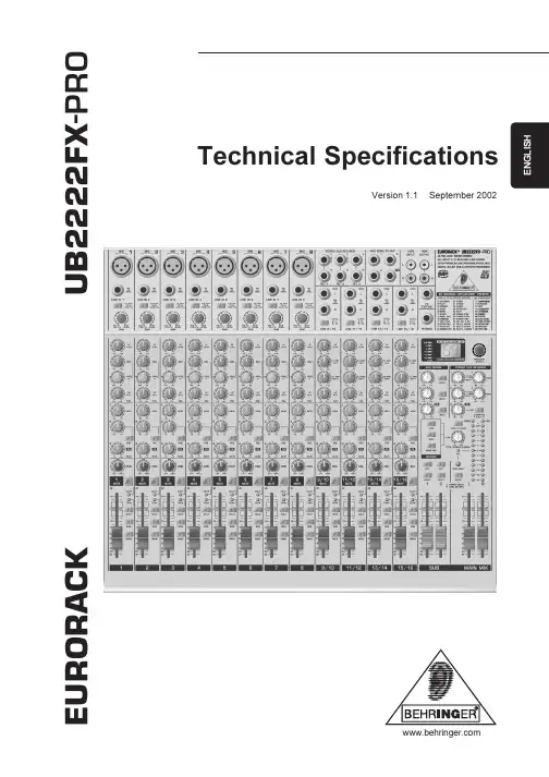
Version 1.1 September 2002Technical SpecificationsE U R O R A C KU B 2222F X -P RO2EURORACK UB2222FX -PROUB2222FX -PROEURORACKUltra low-noise design 22-input 2/2-bus mic/line mixer with premium mic preamplifiers and 24-bit multi-FX processors Ultra low-noise ULN design, highest possible headroom, ultra-transparent audio s 8 new state-of-the-art, studio-grade IMP Invisible Mic Preamps with:130 dB dynamic range for 24-bit, 192 kHz sampling rate inputsUltra-wide 60 dB gain rangeLowest possible distortion 0.0007% (20 Hz - 20 kHz)s Integrated 24-bit digital stereo FX processor with 99 great-sounding VIRTUALIZER presets including reverb,delay, chorus, compressor, tube distortion, vinylizer and more plus 1 kHz test tone generators Effective, extremely musical 3-band EQ with semi-parametric mid band plus switchable low-cut filter on all mono channels s Inserts on each mono channel for flexible connection of outboard equipments 16 balanced high-headroom line inputs with +4/-10 level selection on stereo channelss State-of-the-art 4580 operational amplifiers provide lowest noise and distortion better than 4560 op ampss 3 aux sends per channel: 1 pre fader for monitoring, 1 pre/post fader switchable for monitoring/FX applications,1 post fader (for internal FX or as external send)s Peak LEDs, mute, main mix and subgroup routing switches, solo and PFL functions on all channels s 2 subgroups with separate outputs for added routing flexibility s 3 multi-functional stereo aux returns with flexible routings Balanced main mix outputs with TRS and gold-plated XLR connectors, separate control room, headphones and stereo tape outputs s Control room/phones outputs with multi-input source matrixs Tape inputs assignable to main mix or control room/phones outputs s Switchable +48 V phantom power for condenser microphoness Long-wearing 60 mm logarithmic-taper ALPS ® faders and sealed rotary controlss Internal switch-mode power supply for maximum flexibility (100 - 240 V~), noise-free audio, superior transient response plus lowest possible power consumption for energy saving s Extremely rugged steel construction ensures long life even under the most demanding conditions s Rack mount brackets includeds Manufactured under ISO9000 certified management systemBLOCKDIAGRAM3SPECIFICATIONSMicrophone inputs (IMP Invisible Mic Preamp)Type XLR, electronically balanced,discrete input circuitMic E.I.N. (20 Hz - 20 kHz)@ 0 Ω source resistance-134 dB / 135.7 dB A-weighted @ 50 Ω source resistance-131 dB / 133.3 dB A-weighted @ 150 Ω source resistance-129 dB / 130.5 dB A-weightedFrequency response<10 Hz - 150 kHz (-1 dB),<10 Hz - 200 kHz (-3 dB) Gain range+10 to +60 dBMax. input level+12 dBu @ +10 dB Gain Impedance approx. 2.6 kΩ balanced Signal-to-noise ratio110 dB / 112 dB A-weighted(0 dBu In @ +22 dB gain) Distortion (THD+N)0.005% / 0.004% A-weightedLine inputType1/4" TRS connectorelectronically balanced Impedance approx. 20 kΩ balanced10 kΩ unbalancedGain range-10 to +40 dBMax. input level30 dBuFade-out attenuation1(Crosstalk attenuation)Main fader closed90 dBChannel muted89 dBChannel fader closed89 dBFrequency responseMicrophone input to main out<10 Hz - 90 kHz+0 dB / -1 dB<10 Hz - 160 kHz+0 dB / -3 dBStereo inputsType1/4" TRS connector,electronically balanced Impedance approx. 20 kΩMax. input level+22 dBuEQ mono channelsL o w80 Hz / ±15 dBMid100 Hz - 8 kHz/ ±15 dBHigh12 kHz/ ±15 dBEQ stereo channelsL o w80 Hz /±15 dBLow Mid500 Hz / ±15 dBHigh Mid 3 kHz / ±15 dBHigh12 kHz / ±15 dBAux sendsType1/4" TS connector, unbalanced Impedance approx. 120 ΩMax. output level+22 dBuStereo aux returnsType1/4" TRS connector,electronically balanced Impedance approx. 20 kΩ bal. / 10 kΩ unbal. Max. input level+22 dBu Main outputsType XLR, electronically balancedand 1/4" TRS balanced Impedance approx. 240 Ω balanced /120 Ω unbalancedMax. output level+28 dBuControl room outputsType1/4" TS connector unbalanced Impedance approx. 120 ΩMax. output level+22 dBuHeadphones outputsType1/4" TRS connector, unbalanced Max. output level+19 dBu / 150 Ω (+25 dBm)DSP24-bit Texas Instruments TM Converter24-bit Sigma-Delta,64/128-times oversampling Sampling rate46,875 kHzMain mix system data2NoiseMain mix @ -o o,Channel fader -o o-101 dBMain mix @ 0 dB,Channel fader -o o-93 dBMain mix @ 0 dB,Channel fader @ 0 dB-81 dBPower supplyPower consumption46 WFuse100 - 240 V ~: T 1.6 A H Mains connection Standard IEC receptaclePhysical/weightDimensions (H x W x D)approx. 3 7/8" (97 mm) x 16 1/16"(408 mm) x 14 1/16" (367 mm) Weight (net)approx. 4.8 kgMeasuring conditions:1: 1 kHz rel. to 0 dBu; 20 Hz - 20 kHz; line input; main output; unity gain.2:20 Hz - 20kHz; measured at main output. Channels 1 - 4 unity gain; EQ flat; all channels on main mix; channels 1/3 as far left as possible, channels 2/4 as farright as possible. Reference = +6 dBu.BEHRINGER is constantly striving to manintain the highest professional standards. As a result of these efforts, modifications may be made from time to time to existing products without prior notice. Specifications and appearance may differ from those listed or illustrated.4The information contained in this manual is subject to change without notice. No part of this manual may be reproduced or transmitted in any form or by any means, electronic or mechanical, including photocopying and recording of any kind, for any purpose, without the express writtenpermission of BEHRINGER Spezielle Studiotechnik GmbH.BEHRINGER, EURORACK, VIRTUALIZER, POWERPLAY and ULTRALINK are registered trademarks. ALL RIGHTS RESERVED.TEXAS INSTRUMENTS is a registered trademark of T exas Instruments Incorporated,which is in no way associated or affiliated with BEHRINGER. © 2002 BEHRINGER Spezielle Studiotechnik GmbH.BEHRINGER Spezielle Studiotechnik GmbH, Hanns-Martin-Schleyer-Str. 36-38, 47877 Willich-Münchheide II, GermanyT el. +49 (0) 21 54 / 92 06-0, Fax +49 (0) 21 54 / 92 06-305。

华硕主板BIOS Ami BIOS 设置图解教程一.Main(标准设定)此菜单可对基本的系统配置进行设定。
如时间,日期等其中Primary/Secondary IDE Master/Slave 是从主IDE装置如果你的主板支持SATA接口就会有Third/Fourth IDE Mastert或者更多,他们分别管理例电脑里面各个IDE驱动装置的,如硬盘,光驱等等!因为各个主板的设置不同,所以在此就不详细解说这里的设置了,但是这些一般不用用户自己去设置,一般用默认的就可以,如果有特殊要求,建议用户自己对照说明书的说明进行设置,或者在论坛里单独提问!System Information这是显示系统基本硬件信息的,没有什么好讲(如图)基本设置了解后就进入高级设置了!二.Advanced(进阶设置)如图:这里就是Bios的核心设置了,新手一定要小心的设置,因为其直接关系系统的稳定和硬件的安全,千万不可以盲目乱设!1.大家先看到的是“JumperFree Configuration”(不同品牌的主板有可能不同,也可能没有)再这里可以设置CPU的一些参数,对于喜欢超频的朋友来说这里就是主攻地!(如图)大家可以看到有一个“AI Overclock Tumer”的选项,其中有一些选项,如上图,其中又以“Manual”为关键,选择后会看到如下图:对于CPU超频爱好者这些东西应该了如指掌,CPU的外频设置(CPU External Frequency)是超频的关键之一,CPU的主频(即我们平时所说的P4 3.0G等等之内的频率)是由外频和倍频相乘所得的值,比如一颗3.0G的CPU在外频为200的时候他的倍频就是15,(200MHz*15=3000MHz)。
外频一般可以设定的范围为100MHz到400MHz,但是能真正上300的CPU都不多,所以不要盲目的设置高外频,一般设定的范围约为100-250左右,用户在设定中要有耐心的一点点加高,最好是以1MHz为步进,一点点加,以防一次性加到过高而导致系统无法正常使用甚至CPU损坏!内存频率设定(DRAM Frequency)使用此项设定所安装内存的时钟,设定选项为:200MHz, 266MHz,333MHz, 400MHz, Auto。
中文图解说明,相信认真看一下,一定对你有用,不过这是老版本的BIOS设置,如果朋友的机器是08年后的新机器,就没必要看来,请看另一篇针对新版本的设置吧:新版华硕BIOS设置Basic input output system :基本输入输出系统设置程序是被固化到计算机主板上的ROM芯片中的一组程序,其主要功能是为计算机提供最底层的、最直接的硬件设置和控制。
BIOS设置程序是储存在BIOS芯片中的,只有在开机时才可以进行设置。
CMOS主要用于存储BIOS设置程序所设置的参数与数据,而BIOS设置程序主要对技巧的基本输入输出系统进行管理和设置,是系统运行在最好状态下,使用BIOS设置程序还可以排除系统故障或者诊断系统问题。
在我们计算机上使用的BIOS程序根据制造厂商的不同分为:AWARD BIOS程序、AMI BIOS程序、PHOENIX BIOS程序以及其它的免跳线BIOS程序和品牌机特有的BIOS程序,如IBM等等。
目前主板BIOS有三大类型,即AWARD AMI和PHOENIX三种。
不过,PHOENIX已经合并了AWARD,因此在台式机主板方面,其虽然标有AWARD-PHOENIX,其实际还是AWARD的BIOS的. Phoenix BIOS 多用于高档的586原装品牌机和笔记本电脑上,其画面简洁,便于操作。
下面BOOT是硬盘情况设置,列表中存在PRIMARY MASTER 第一组IDE主设备;PRIMARY SLAVE 第一组IDE从设备;SECONDARY MASTER 第二组IDE主设备;SECONDARY SLAVE 第二组IDE从设备。
这里的IDE设备包括了IDE硬盘和IDE光驱,第一、第二组设备是指主板上的第一、第二根IDE数据线,一般来说靠近芯片的是第一组IDE设备,而主设备、从设备是指在一条IDE数据线上接的两个设备,大家知道每根数据线上可以接两个不同的设备,主、从设备可以通过硬盘或者光驱的后部跳线来调整。
华碩 BIOS设定(shè dìnɡ)方式說明BIOS(基本輸入輸出系統)为出厂時燒錄在主机板上FlashROM之程式,其扮演著硬体与作业系統溝通的角色,透过(tòu ɡuò)BIOS可设定系統操作模式及硬体之相关參数。
系統关机時,BIOS会先進行关机自我測試 (POST)。
此時,按下<Del>鍵即可進入BIOS设定主画面。
其功能及操作(cāozuò)方式說明如下: 【StandardCMOSSetup】系統基本(jīběn)參数设定此选項之功能主要为设定系統基本參数。
使用者可透过(tòu ɡuò)移動亮棒的方式來选择欲设定的項目,用<PageUp>及<PageDown>鍵來修改內容。
在每一选項中,您可按<F1>鍵來顯示該选項可供选择之內容。
Date(日期)设定目前日期。
可设定之範圍为:Month(月):1至12Day(日):1至31Year(年):至2079Time(時間)设定目前時間。
可设定之範圍为:Hour(時):00至23Minu7te(分):00至59Second(秒):00至59HardDisks(硬盘)此选項用來设定系統中所有IDE硬盘(PrimaryMaster/Slave;SecondaryMaster/Slave)之類型。
各选項說明如下: Auto:允許系統关机時自動偵測硬盘類型並加以设定。
None:未安裝硬盘。
User:允許使用者自行设定(shè dìnɡ)硬盘之相关參数。
包括CYLS(磁柱数),HEAD(讀寫頭数),PRECOMP(寫入預補償),LANDZ(放位置)。
在硬盘机所附之說明書均磁頭停詳載這些規格。
[請注意(zhù yì)]:BIOS不支援SCSI硬盘之设定。
至於MODE的选項有三種:1.NORMAL模式(móshì):为傳統之標準模式(móshì),支援硬盘机容量最高至528MB。