浇口及流道设计
- 格式:ppt
- 大小:1.04 MB
- 文档页数:55
2_05浇口和流道设计浇口和流道设计是塑料注塑成型过程中非常重要的一环,它们的设计质量直接关系到成型件的质量和生产过程的稳定性。
本文将详细介绍浇口和流道设计的意义、原则以及一些常见的设计方法。
一、浇口的设计意义1.提供熔融塑料进入模具腔体的通道,确保塑料充填腔体均匀;2.控制塑料进入速度和压力,避免短充、气泡等缺陷;3.有效防止熔融塑料对模具磨损和腐蚀;4.方便脱模和切除浇口处余料。
二、浇口设计的原则1.浇口位置应选择在产品外表面影响不大的部位,如底部、壁角等;2.浇口形状应简单,避免锐角和复杂几何形状,以利于塑料顺利进入腔体;3.浇口尺寸应合理,既能保证塑料充填,又不至于过大过长造成浪费和废料;4.浇口和产品分离的方式应考虑生产效率和产品外观要求;5.浇口设计要充分考虑熔融塑料的物理性质和流动性,避免局部过热或过冷。
三、流道设计的意义1.将浇注的熔融塑料传递到各个腔体,使得产品充填均匀;2.控制塑料的流速和压力,避免气泡、短充等缺陷;3.提供相对稳定的压力和温度环境,促进熔融塑料的密度均匀;4.对于多腔体模具,流道设计还要充分考虑产品产量的平衡。
四、流道设计的原则1.流道的直径、长度和截面积要合理选择,以保证塑料在流道内的流速符合流动性要求;2.流道和浇口的连接处要能够顺利过渡,避免过渡断面过小或过大造成流动不畅;3.流道的布置应考虑与模具结构的配合,以便于流道的加工和安装;4.尽量减少流道的弯曲和分支,以减小塑料流动阻力和热量损失;5.流道的表面要光滑,减小摩擦阻力和物料附着。
总之,浇口和流道设计是塑料注塑成型过程中关键的一环,其设计质量直接影响产品的质量和生产过程的稳定性。
合理的浇口和流道设计可以确保塑料充填均匀、避免气泡和短充等缺陷,并提高生产效率和降低生产成本。
因此,在进行浇口和流道设计时,需要综合考虑材料的流动性能、产品的几何形状、模具结构等因素,并遵循一定的设计原则。
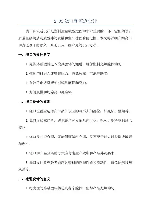
流道设计基本原理普通的流道系统(Runner System)也称作浇道系统或是浇注系统,是熔融塑料自射出机射嘴(Nozzle)到模穴的必经通道。
流道系统包括主流道(Primary Runner)、分流道(Sub-Runner)以及浇口(Gate)。
下图显示了典型的流道系统组成。
●主流道:也称作主浇道、注道(Sprue)或竖浇道,是指自射出机射嘴与模具主流道衬套接触的部分起算,至分流道为止的流道。
此部分是熔融塑料进入模具后最先流经的部分。
●分流道:也称作分浇道或次浇道,随模具设计可再区分为第一分流道(First Runner)以及第二分流道(Secondary Runner)。
分流道是主流道及浇口间的过渡区域,能使熔融塑料的流向获得平缓转换;对于多模穴模具同时具有均匀分配塑料到各模穴的功能。
●浇口:也称为进料口。
是分流道和模穴间的狭小通口,也是最为短小肉薄的部分。
作用在于利用紧缩流动面而使塑料达到加速的效果,高剪切率可使塑料流动性良好(由于塑料的切变致稀特性);黏滞加热的升温效果也有提升料温降低黏度的作用。
在成型完毕后浇口最先固化封口,有防止塑料回流以及避免模穴压力下降过快使成型品产生收缩凹陷的功能。
成型后则方便剪除以分离流道系统及塑件。
●冷料井:也称作冷料穴。
目的在于储存补集充填初始阶段较冷的塑料波前,防止冷料直接进入模穴影响充填质量或堵塞浇口,冷料井通常设置在主流道末端,当分流道长度较长时,在末端也应开设冷料井。
流道设计基本原则模穴布置(Cavity Layout)的考虑●尽量采用平衡式布置(Balances Layout )。
●模穴布置与浇口开设力求对称,以防止模具受力不均产生偏载而发生撑模溢料的问题。
如图2的设计就以对称者较佳。
●模穴布置尽可能紧凑以缩小模具尺寸。
如图3(b)的设计就模具尺寸考虑而言优于图3(b)的设计。
流动导引的考虑●能顺利地引导熔融塑料填满模穴,不产生涡流,且能顺利排气。
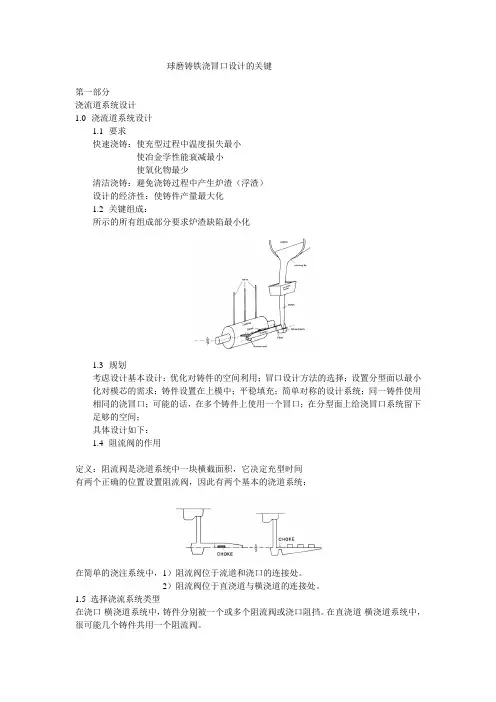
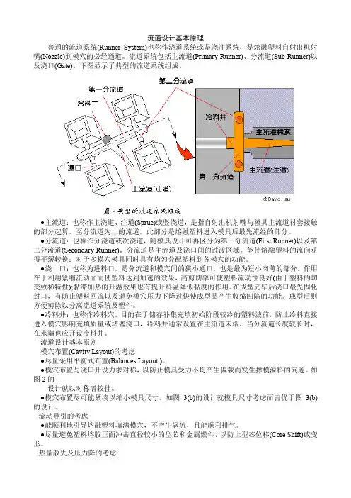
球磨铸铁浇冒口设计的关键第一部分浇流道系统设计1.0浇流道系统设计1.1要求快速浇铸:使充型过程中温度损失最小使冶金学性能衰减最小使氧化物最少清洁浇铸:避免浇铸过程中产生炉渣(浮渣)设计的经济性:使铸件产量最大化1.2关键组成:所示的所有组成部分要求炉渣缺陷最小化1.3规划考虑设计基本设计:优化对铸件的空间利用;冒口设计方法的选择;设置分型面以最小化对模芯的需求;铸件设置在上模中;平稳填充;简单对称的设计系统;同一铸件使用相同的浇冒口;可能的话,在多个铸件上使用一个冒口;在分型面上给浇冒口系统留下足够的空间;具体设计如下:1.4阻流阀的作用定义:阻流阀是浇道系统中一块横截面积,它决定充型时间有两个正确的位置设置阻流阀,因此有两个基本的浇道系统:在简单的浇注系统中,1)阻流阀位于流道和浇口的连接处。
2)阻流阀位于直浇道与横浇道的连接处。
1.5 选择浇流系统类型在浇口-横浇道系统中,铸件分别被一个或多个阻流阀或浇口阻挡。
在直浇道-横浇道系统中,很可能几个铸件共用一个阻流阀。
使用直浇道-横浇道系统在一个模具里生产大量小型件,这是不切实际的对每个铸件分别设置阻流阀(阻流阀尺寸非常小),极大的依赖于模具技术及浇注温度大部分情况下是使用浇口-横浇道系统浇口-横浇道系统与直浇道-横浇道系统特点的结合形成混合系统。
这通常用在要求运输铁水到复杂的铸件型腔的流道系统中。
1.6摩擦并非直浇道顶部所有铁水的潜能都可以转换为铸造型腔中的机械能随着铁水与型腔内壁的撞击和铁水之间的撞击,一些潜能损失在摩擦上由于摩擦造成的损失,延长了模型填充时间,必须考虑何时计算阻流阀截面积和浇铸时间。
选择fr,摩擦损失因子,作为能量损失的估计值对于薄壁平板:fr—0.2对于厚重立方体:fr---0.81.7浇铸时间尽可能快的符合人们的能力及生产例程推荐的浇注时间:非常近似的指导,铸件质量+冒口质量1.8阻流阀的横截面积对总的浇铸质量选择最快的实际浇铸时间(t,sec.)选择合适的fr值确定总的浇铸体积/阻气阀(V)V是所有铸件及冒口,特定阻流阀的下游之和体积=质量/密度液态铸铁,密度=0.25磅/立方英尺或0.007KG/cm3Determine effective ferrostatic head in sprue (H.)确定铸件在上模中的高度(b.)根据Torricelli,铁水在阻流阀的流速当铸件完全处在下模,当铸件完全位于上模,当铸件位于上模和下模中,可以从下面的图谱中,选择合适的Ac图谱数据基于平均上模高度(依铸造不同而变化)。

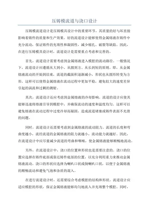
压铸模流道与浇口设计压铸模流道设计是压铸模具设计中的重要环节,其质量的好与坏直接影响着铸件的质量和生产效果。
好的流道设计能够使得金属熔液在铸件中充分流动,保证铸件的充填性和凝固性,减少缩孔、破裂等缺陷。
因此,在进行压铸模具设计时,流道设计是需要重点考虑和完善的。
首先,流道设计需要考虑到金属熔液进入模腔的流动路径。
一般情况下,流道设计应遵循从大到小、从圆到方、从长到短的原则。
即,从金属熔液流动的开始到结束,流道的截面积逐渐减小,形状也从圆形转变为方形。
这样可以使得金属熔液在流动过程中更加平稳,避免较大的速度差异引起的涡流和过剩的测射。
其次,流道设计还应考虑到金属熔液的冷却影响。
流道的设计应使其能够迅速将熔液引导到模腔中,并确保流动的速度和温度均匀。
这样可以避免熔液在流动过程中过度冷却而凝固,造成流道堵塞或铸件表面不光滑的问题。
同时,流道设计还需要考虑到金属熔液的流动阻力。
流道的长度和弯曲度越小,流经流道的金属熔液的阻力就越小,流动能力就越好。
因此,在流道设计中应尽量减少流道的弯曲和咽喉,使金属熔液能够顺畅地流动。
另外,在流道设计中,浇口的位置和形状也是需要注意的。
浇口的位置应选择在铸件底部或靠近铸件底部的位置,以充分利用重力来推动金属熔液流动。
浇口的形状应选择为喇叭口状或倒喇叭口状,以便于金属熔液的顺畅流动和避免气泡和杂质的混入。
在进行流道设计时,还需要综合考虑模腔的结构和形状。
流道设计应适应模腔的形状,保证金属熔液能够均匀地流入并充填整个模腔。
同时,流道的尺寸也需要根据铸件的尺寸和结构来进行合理确定,以保证铸件的充填性能和凝固性能。
需要注意的是,流道设计还应结合具体的铸造材料和生产工艺来进行综合考虑和设计。
不同的铸造材料和生产工艺对流道的要求和设计方法也会有所不同。
总结起来,压铸模流道设计的目标是使金属熔液在模腔中充分流动,保证铸件的充填性能和凝固性能。
良好的流道设计能够避免铸件缺陷,提高生产效率和质量。
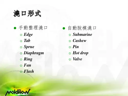


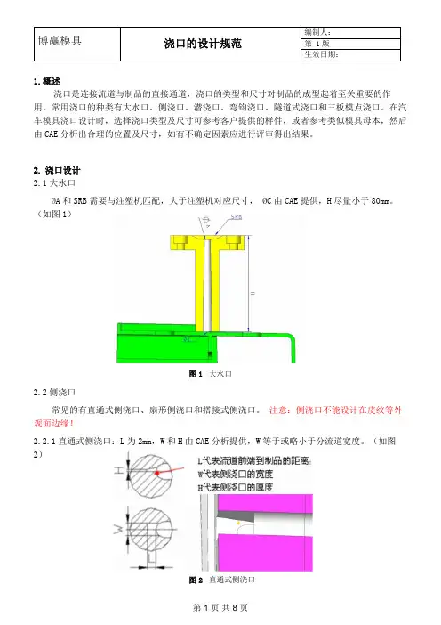
1.概述浇口是连接流道与制品的直接通道,浇口的类型和尺寸对制品的成型起着至关重要的作用。
常用浇口的种类有大水口、侧浇口、潜浇口、弯钩浇口、隧道式浇口和三板模点浇口。
在汽车模具浇口设计时,选择浇口类型及尺寸可参考客户提供的样件,或者参考类似模具母本,然后由CAE 分析出合理的位置及尺寸,如有不确定因素应进行评审得出结果。
2. 浇口设计2.1大水口ØA和SRB 需要与注塑机匹配,大于注塑机对应尺寸, ØC 由CAE 提供,H 尽量小于80mm。
(如图1)2.2侧浇口常见的有直通式侧浇口、扇形侧浇口和搭接式侧浇口。
注意:侧浇口不能设计在皮纹等外观面边缘!2.2.1直通式侧浇口:L 为2mm,W 和H 由CAE 分析提供,W 等于或略小于分流道宽度。
(如图2) 图1 大水口图2 直通式侧浇口2.2.2扇形侧浇口:L为2mm,浇口尺寸CAE 提供。
(如图3)图3 扇形侧浇口2.2.3搭接式侧浇口:L 为2mm,W 为1.5mm,H2为1.2-1.8mm,T 为产品壁厚,H1为分流道高度。
(如图4)图4 搭接侧浇口2.3潜浇口多设计在产品的筋位或侧壁上,如果产品形状无法设计可增加辅助筋位(如图5)或借助顶杆(如图6)。
主要分推切式和拉切式,浇口的截面形状基本形式是圆形(如图7),可变化为矩形(如图8)。
图5 加辅助筋位潜浇口图6 加辅助顶杆潜浇口图8 截面为矩形潜浇口图7 基本形式潜浇口2.3.1基本形式的潜浇口参数(如图9)。
图9 基本形式的潜浇口2.3.2辅助顶杆潜浇口参数(如图10)。
图10 基本形式的潜浇口2.3.3拉切式潜浇口参数(如图11)。
图11 拉切式潜浇口2.3.4对于潜浇口,浇口和流道最好分别设计到前模和后模,这样浇口拉断时受力和变形都比较好,但是如果流道设计到前模,热流道喷嘴需要加工形状,所以潜浇口设计时不限制浇口和流道是否分别在前后模,但是浇口的设计和流道的设计都要符合标准。
注塑模具设计之浇口与流道设计
1.浇口设计:
浇口是塑料进入模具腔体的通道,直接影响产品的质量和外观。
浇口设计应遵循以下原则:
1.1浇口的位置应尽量选择在产品的无重要表面或结构上,以减少产品上的痕迹和缺陷。
1.2浇口的形状应尽量简单,以便于注塑成型时的塑料流动,避免气泡和短流等缺陷。
1.3浇口的大小应根据产品的要求确定,过大会导致浇注时间过长,过小会导致注塑过程压力过高。
1.4浇口与产品的交界处应尽量平滑,以减少痕迹和切除时的损耗。
1.5浇口的数量应尽量减少,多个浇口可能导致注塑不平衡,造成产品尺寸不一致。
2.流道设计:
流道是浇口与模具腔体之间的连接通道,它将塑料从浇口引导到模具腔体中。
流道设计应遵循以下原则:
2.1流道的形状应尽量简单,避免过多的转弯或急角,以减少流动阻力和塑料流动不均匀导致的缺陷。
2.2流道的长度应尽量短,以减少注塑周期和塑料的凝结时间。
2.3流道的截面积应逐渐减小,以确保塑料在流道中均匀流动,避免气泡的产生。
2.4流道与模具腔体的接头处应尽量平滑,避免塑料流动时的冲击和挤压,以减少产品上的痕迹和缺陷。
总结起来,注塑模具设计中的浇口与流道设计需要考虑产品的要求、材料的特性和注塑工艺的要求等多个因素,以使得产品的质量达到最佳状态。
在实际设计中,需要结合实际情况进行调整和优化,不断改进和提高设计水平。
压铸模流道与浇口设计压铸是一种通过将熔融的金属注入到模具中,形成所需形状的工艺。
在这个过程中,流道和浇口是非常重要的,因为它们决定了金属液的流动路径和充模情况。
对于大多数压铸件而言,流道主要包括归流道和分流道。
归流道是将熔融金属从浇注口引导到模腔的通道,而分流道则将金属液引导到各个腔室中。
流道的设计应该尽可能地减小金属液的流速和流动阻力,确保金属液能够均匀地填充模腔,并且不会产生气泡或其他缺陷。
在设计流道时,要考虑到金属的流动行为和模具的结构。
流道的截面应该逐渐增大,以保证金属液能够均匀地流动。
此外,流道的长度和弯曲程度也需要适当调整,以减小流动阻力和流动速度。
在流道的设计中,还应该考虑到金属的流场分布和模具的加热和冷却情况,以确保金属液能够流动到模腔的每个角落。
浇口的设计也是非常重要的。
浇口是金属液注入模具的入口,直接影响到金属液的充模情况和充模速度。
一个合理的浇口设计应该能够使金属液均匀地分布到模腔中,并且不会产生气泡或其他缺陷。
浇口的设计要尽可能地减小气体的进入,并且能够方便地从铸件中排出。
浇口的位置和形状也需要仔细考虑。
一般来说,最好选择在模具的上部或侧部设置浇口,这样可以减少气体的进入并且方便排气。
浇口的形状可以是圆形、椭圆形或矩形,具体要根据铸件的形状来确定。
在浇口的设计中,还应该考虑到金属液的充模速度、充模压力和浇注温度,以确保铸件的质量。
在流道和浇口的设计中,还需要考虑到模具的制造成本和生产效率。
流道和浇口的设计应该尽可能地简单和经济,同时也要能够满足产品的质量要求。
此外,在模具的制造过程中,还需要考虑到流道和浇口的冷却和加热情况,以确保模具的寿命和稳定性。
总之,流道和浇口的设计是压铸工艺中非常重要的环节。
一个合理的流道和浇口设计可以确保金属液能够均匀地填充到模腔中,并且不会产生气泡或其他缺陷。
同时,流道和浇口的设计还需要考虑到模具的制造成本和生产效率。
通过合理的流道和浇口设计,可以提高压铸件的质量和性能。
Runner and gate design.The Important FeaturesIntroduction;The following is a brief summary of the important factors to consider when designing runner and gating systems for Zinc and Aluminium pressure die casting dies.In the past runner systems were designed using empirical knowledge and developed using trial and error methods which involved excessive time and often multiple die trials. Today, computer programmes exist which eliminate these problems and are able to give good results immediately but, many of the most basic design issues are often neglected during the design stage particularly if the die is designed by the tool maker without consultation to the die casting technicians.These brief notes are intended as guidelines for use during training and as an aide memoiré for die design technicians and designers. They are not intended to cover all aspects of die design practice.____________________________Objective:The runner and gate system should achieve the following in basic terms:•Produce a casting of the specified quality; in terms of finish, size and tolerance, casting integrity, mechanical properties, cycle time and consistency.••Achieve first time success; to avoid wasted time on successive machine trials, delays in delivery of samples, loss of customer confidence and excessive die developmentcosts.••Provide optimum yield; increases efficiency by optimising the casting to runner yield ratio, improve metal losses due to lower re-melt weights, reduces cycle times due toimproved thermal efficiency.THE BROCK METAL COMPANY LIMITED,WALSALL ROAD. NORTON CANES, CANNOCK, STAFFS, UK WS11 9NR.Runner and gate design.Influencing factors.Designing a runner system:Selection of the machine should be based on several factors but not just shot weight and platen area. Most machines are supplied with a PQ2 diagram or one exists from measurements taken on other similar machines. Runner designs should be based on machine performance with a given plunger or shot sleeve diameter, known hydraulic pressure and in the case of hot chamber die casting the nozzle size. Both projected area and lock tonnage should also be considered if the proposed runner plus casting is liable to approach the machine limits.Casting geometry:The cavity should be positioned to promote the best cavity fill conditions while accommodating essential die features such as core slides, cooling channels, sensitive casting features, number of cavities and robotic removal constraints. Other process criteria such as second operation locations, clipping orientation, break off de-gating and finishing requirements should also be considered before the cavity position is decided.Uniform flow path:The runner should establish a uniform metal flow rate deigned to promote the best hydraulic system, stable metal pressure and velocity. Most computer design programmes will control these features but the designer will still have institute a flow path allows these features conform to the desired parameters.Cavity fill conditions:Modern pressure die casting machines often have more power at the shot end than is required to achieve the optimum fill conditions. Consequently, the performance offers many gate area options capable of achieving the desired fill conditions – the designer must select the most suitable based on the casting specification and process limitations.Cavity fill pattern:Is invariably decided by the casting geometry and gate position but the metal pressure and velocity will have influence but to a lesser extent. The influence of casting features such as vertical surfaces and ribs, variable section thicknesses, isolated bosses and cores must be considered when the gate position is decided.Venting and overflow wells:Should all be considered at the design stage – are directly related to the cavity fill conditions and casting geometry but also the introduction of over flow wells or pockets may have significant cost implications.THE BROCK METAL COMPANY LIMITED,WALSALL ROAD. NORTON CANES, CANNOCK, STAFFS, UK WS11 9NR.Runner and gate design.Machine Performance.Effects of change.Injection pressure: Reduce or increase .• Increased injection pressure – will increase flash, raise galvanising and die erosion.Optimum pressure levels will improve casting integrity, maintain speed and velocity and improve cavity fill conditions.Reduced injection pressure – reduces flow rates, and static metal pressure on hot chamber pressure die casting machines.• Plunger diameter – on hot chamber die casting machines smaller plungers give thebest casting results with higher injection pressure and faster delivery. On aluminium cold chamber machines plunger diameter choice is less critical but effect is far more significant in performance terms - increasing delivery velocity and reducing cavity fill times.• Plunger speeds - high terminal velocities can produce pressure spikes on older diecasting machines leading flash and die wear. High gate speeds result in expensive die maintenance due to die erosion and galvanising.• Runner Area/volume - die designer should create a uniform flow through the runnerby establishing nozzle area (hot chamber) as the largest section in the runner.Progressively reducing the cross sectional area of the runner at each section to the gate which should be the smallest area in the runner system. Similarly, on cold chamber dies the sprue post runner should be the largest runner section down to the gate which should be smallest section of the runner.Flow rate histogram.N o z z l e a r e aGateAreaTHE BROCK METAL COMPANY LIMITED,WALSALL ROAD. NORTON CANES, CANNOCK, STAFFS, UK WS11 9NR.Runner and gate design.Runner features‘Y’ Junction not ‘T’‘Y’ JunctionReduces area and increases pressure progressively.‘T’ JunctionIncreases volume at the junction creating low pressure area at the centre of the gate.THE BROCK METAL COMPANY LIMITED,WALSALL RO D. NORTON CANES, CANNOCK, STAFFS, UK WS11 9NR.ARunner and gate design .Runner featuresTaper tangential runner - with shock absorber – showing section change A to B toSmaller diagram – illustrates poor runner design small access radius,increased e taper,maintain pressure and velocityrunner volume at the radius, small runner cross section at the end of th and no shock absorber.THE BROCK METAL COMPANY LIMITED,WALSALL RO D. NORTO NES, CANNOCK, STAFFS, UK WS11 9NR.A N CARunner and gate design .Runner featuresDrawings – Show section through sprue posts on Aluminium (top ) and Zinc (bottom )This area most commonly inte d incorrectly by toolmakers.Note; Th radiusdies.rprete e reduction from the sprue faces to die face and the size and blend which are struck from the same centre to ensure even transition from sprue to die.THE BROCK METAL COMPANY LIMITED, WALSALL ROAD,. NORTON CANES, CANNOCK, STAFFS, UK WS11 9NR.Runner and gate design .Runner featuresRunner sections: Need to be adjusted by differing percentages tor l10% reduction in runnerarea- down stream of metalaccommodate larger angular direction changes30% reduction in runner a ea - down stream of meta flow – for 900 bend.flow – for a 200 bend.THE BROCK METAL COMPANY LIMITED, WALSALL ROAD. NORTON CANES, CANNOCK, STAFFS, UK WS11 9NR,Runner and gate design .Gate Areasate Areas:ptimum for Zinc alloy pressure die-casting :ed / velocity – 35 – 45 metres per second.ish – 20 milli seconds or functionalOptimum for Aluminium alloy pressure die casting:5 metres per second..ortant on large castings asFil a etry: has the largest influence on cavity flow paths – high metal velocitypplied to vertical casting faces causes turbulence, galvanising and impedes metal. All of which and areas; It is possible to assess parts of the casting separately nd this may be advantageous if they are unlikely to be fed directly from the gate. of a given part sing separate gates for each zoned area. This will often improve fill characteristics low: It must be stressed that the gates and runner both fluence flow direction. Once the runner is established metal under pressure will G O • Gate spe • Cavity fill time – plated or powder coated fin parts – 40 milli seconds.• Gate depth – 0.15 – 0.5 mm.• Gate speed / velocity – 25 to 3To avoid die erosion and control cavity fill characteristics • Cavity fill time – end of fill temperature is most imp solidification can occur prior to cavity filling.• Depth 1.25 – 3 mm (1.5 mm minimum for machine intensification to be effective ).l P ttern:Casting geom a can result in expensive die repairs / maintenance. Section changes and cores change pressure and direction and these effects need to be considered and understood when considering gate position options.Zones volumes a Using computer programmes allows each separate zone to be quantified in volume and surface area terms. If treated as un-gated the fill time and end of fill temperature can be determined as a comparison with the main body of the total casting.Gating separate zones: It is possible also to examine separate zones u and reduce the risks of defects. The uses of multiple gates are not a risk if designed and implemented correctly.Runner will direct metal f in enter the cavity in the same direction and flow angle. Varying injection speed and metal pressure may alter this angle slightly but this is only a fine tuning method.THE BROCK METAL COMPANY LIMITED, WALSALL ROAD. NORTO NES, CANNOCK, STAFFS, UK WS11 9NR,N CARunner and gate design .Fill pattern.Influence of casting geometry ertain casting shapes are best filled in a predetermined way, if the toolingre the depth is 50% of the edge length or more he box :C configuration allows. Deep boxes, whe can be fed using the gate runner configuration shown below – alternatively t can be turned through 450 to shorten the runner distance and improve shot yield.THE BROCK METAL COMPANY LIMITED, WALSALL ROAD. NORTON CANES, CANNOCK, STAFFS, UK WS11 9NR,Runner and gate design .Fill pattern.vals or round castings: Try to fill the centre first using either a runneronfiguration below or a more traditional fan feed. With fan feeds it is essential to getO c the ratio of the approach angle and width of gate correct.THE BROCK METAL COMPANY LIMITED, WALSALL ROAD. NORTON CANES, CANNOCK, STAFFS, UK WS11 9NR,Runner and gate design .Fill pattern.nnular rings: Can be fed using the runner configuration indicated below. A smallver flow well should positioned in the centre hole to take away any lubrication fume A o and another well placed on the out side perimeter adjacent to the last segment of the part to fill.THE BROCK METAL COMPANY LIMITED, WALSALL ROAD. NORTON CANES, CANNOCK, STAFFS, UK WS11 9NR,Runner and gate design .Fill pattern.Rectangular Plates: Fill across shortest distance whenever possible – t cut downow distance and increase end of fill temperature. It is therefore advisable to avoido fl the option shown in the upper diagram if possible.THE BROCK METAL COMPANY LIMITED, WALSALL ROAD. NORTON CANES, CANNOCK, STAFFS, UK WS11 9NR,Runner and gate design .Fill pattern.Diagram show e – to resolve problems ofporosity and poor ximately 6 mm deep, with a gate depth of between 1.8 and 2.5 mm. Casting weighed approximately 5 Kg and with a flow distance of 510 m s: runner developed over a period of tim fill results. The darker blue area is appro m.THE BROCK METAL COMPANY LIMITED, WALSALL ROAD. NORTON CANES, CANNOCK, STAFFS, UK WS11 9NR,Runner and gate design .Fill pattern.Diagram show niform gate thickness of 2 mm. The runner and a subsequent increase in yield of 18% and a reduction in pr ected area of some 22% allowing improved shot speed and increased in injecs: Revised runner with balance fill and u shows reduced shot weight by over 1 Kg oj tion pressure.THE BROCK METAL COMPANY LIMITED, WALSALL ROAD. NORTON CANES, CANNOCK, STAFFS, UK WS11 9NR,Runner and gate design .Vents and Overflow wells.Points to remember:• Over flow w tal flow, but rarely remove gas and fume as the cavity is normal sealed before they become a .only work for less than half of the cavity fill time as they arefinal fill is achieved. • Over flow wells are a poor method of die heating both inefficient and wasteful.See reference material from ILZRO, IZA.JWTSep ells can be used to change or divert mective ly • Similarly vents can sealed off before the• Use only one connection per over flow to avoid back feeding through theoverflow and reintroducing gas and cold metal. • Always vent over flow wells – as a precaution.Many are lost before re-melting and therefore increase metal losses.t 05 – issue 5。
注塑模具的流道与浇口设计
塑料熔体从注射成型机的喷嘴经主流道、流道、浇口进人模腔。
模腔的人口被称为浇口。
为了防止喷嘴末端的固化冷料进人模腔,在流道的末端应该设计冷料井。
01流道
流道是从主流道到浇口间的重要通道,是注塑机喷嘴射出的熔融塑料的流动通道。
流道应被设计成低阻力和防止冷却。
通常,流道被设计成梯形或圆形。
常见流道的形状
对于多腔模具,为了得到好的尺寸精度,流道的设计十分重要,下图典型的多腔模具的流道设计。
多腔模具流道
02浇口
浇口系统设计,如位置、数目、几何形状和尺寸对生产效率和尺寸精度是十分重要的,浇口的作用总结如下:
1.控制流入模腔的塑料熔体的体积和方向
2.固化前,在模腔内封闭熔料并阻止熔体回流到流道
3.由于黏性耗散引起的热而生成
4.易于切下流道,简化制品的后处理
分类:
非限制性浇口称为直浇口,如下图所示,这种浇口形式的模具设计简单,操作容易,成型容易并减小收缩。
但这种浇口成型周期变长,并易出现如裂纹、翘曲和残余应力等成型缺陷。
直浇口。