日立NPH-HLI变频器使用说明.
- 格式:pdf
- 大小:400.80 KB
- 文档页数:12

1日立变频器介绍日立变频器是日立电机公司生产的一种用于调节电动机的运行速度和输出功率的电子设备。
它采用了先进的变频技术,可以实现电动机的无级调速,适用于各种不同的工业应用领域。
本文将介绍日立变频器的基本原理、工作方式、优点和应用领域。
日立变频器的基本原理是通过控制电源的频率来改变电动机的转速。
它以电源的交流电输入为基础,经过整流、滤波、逆变等处理,将交流电转换为直流电,然后再通过逆变器将直流电转换为可变频率的交流电。
这样,就可以改变电动机的转速和输出功率。
日立变频器的主要组成部分包括整流器、直流母线、逆变器和控制系统。
日立变频器的工作方式可以分为两种:开环控制和闭环控制。
开环控制是指变频器根据用户设置的频率进行输出,但无法实时检测电动机的转速和负载情况。
闭环控制则是在开环控制的基础上,加入了转速和负载的反馈信号,通过控制器对输出频率进行调整,以实现更精确的控制。
闭环控制在对转速和负载要求较高的应用中更为常见。
日立变频器具有多种优点,使其成为许多工业应用的首选。
首先,日立变频器可以实现无级调速,可以满足不同工况下的转速要求,提高生产效益。
其次,通过精确控制电动机的输出功率,可以降低能源消耗和运行成本。
同时,日立变频器还具有运行稳定、响应速度快、可靠性高等特点,可以提高设备的运行稳定性和可靠性。
日立变频器广泛应用于各个领域的工业应用中。
例如,它可以用于风机、泵、卷扬机、压缩机、注塑机等机械设备的调速控制。
在水处理、制药、矿山、钢铁等行业中,日立变频器可以实现对设备的精确控制,提高生产效率和质量。
此外,日立变频器还可以应用于电梯、起重机、电动汽车等领域,为各种交通和运输设备提供可靠的动力输出。
总的来说,日立变频器是一种先进的电子设备,通过调节电动机的转速和输出功率,可以满足各种工业应用的需求。
其无级调速、运行稳定、响应速度快等优点使其成为众多工业领域的首选。
随着科技的不断进步,日立变频器将继续发展,为工业自动化和智能化提供更多可能性。

HLP-SH110系列变频器快速使用指南1. 基本信息2. 变频器尺寸F0~F5-2机箱F7~F8机箱5. 操作与显示5.1 操作面板5.4参数恢复出厂值1. 设置参数C14.22 = 2;2. 变频器断电并重新上电,面板显示E.80;3. 在按OFF 键完成参数初始化;4. 按下AUTO 确保变频器处于外部控制状态。
3. 变频器主回路连接步骤一:将电机地线、电源地线连接到PE 端子上,如下图1所示;步骤二:将电机连接到变频器U、V 和W 端子上,如下图2所示;步骤三:如需连接制动电阻,请将制动电阻连接在+BR、-BR 端子上,如下图3所示;步骤四:将主电源连接到变频器端子R、S 和T 端子(单相接R、T)上,如下图4所示;2021-01版133R02655.2 操作面板启停控制1.按下操作面板上的“HAND”键启动变频器;2.旋转增量式电位器即可调节输出频率,默认每旋转一格,频率增加或减速0.1Hz,可通过参数C00.47修改每一格的步长。
3.按下操作面板上的“OFF”键停止变频器。
注意:在本地运行模式下,操作面板上的增量式电位器是变频器频率唯一的来源。
本地运行模式一般用于调试。
5.3数字量输入端子启停控制变频器上电后,按下面板上的AUTO 键进入远程模式(外部端子和通讯控制开启),短接数字量输入端子FOR 和COM 启动变频器,断开则停止变频器。
此文档将指导客户完成基本的安装、接线和功能调试。
如需获得详细使用说明书,请与本产品经销商联系。
产品出厂前均经过严格检测和包装,如发现变频器损坏、型号不对、缺少附加配件等异常情况,请通知本产品经销商或本公司相关人员。
任何产品问题通过以下方式联系海利普。
400-8095-335微信公众号海利普变频器参数号名称设定范围单位出厂值*C01.07应用功能0:无效;1:摆频控制;-0*C01.10电机类型0:异步电机1:表贴式同步电机SPM(隐级)2:非饱和内嵌式同步电机(凸级)3:饱和内嵌式同步电机IPM(凸级)-0C01.14同步电机阻尼系数0~250%120C01.15低速高通滤波时间0.01~20.00s 0.8C01.16高速高通滤波时间0.01~20.00s 0.8C01.17电压滤波时间0.001~1.000s0.5*C01.20电机额定功率取决于电机数据kW **C01.22电机额定电压50~1000V **C01.23电机额定频率20~400Hz **C01.24电机额定电流取决于电机数据A **C01.25电机额定转速100~9999rpm *C01.26电机额定转矩0.1~6553.5N·m 0*C01.29电机自学习0:无效1:静态完全自学习2:静态简易自学习3:静态完全自学习 + 反电动势学习4:静态完全自学习 + 系统惯量学习5:静态完全自学习 + 反电动势学习 + 系统惯量学习-0*C01.30定子电阻取决于电机参数Ω**C01.31转子电阻取决于电机参数Ω**C01.33定子漏电抗取决于电机参数mH **C01.35电机主电抗取决于电机参数mH *C01.37同步电机D 轴电抗取决于电机数据*C01.38同步电机Q 轴电抗取决于电机数据**C01.39电机极数2~100P 4*C01.401000RPM 时电机EMF0~9000V**C01.42电机线长度0~150m **C01.44同步电机D 轴饱和电感取决于电机数据Ω**C01.45同步电机Q 轴饱和电感取决于电机数据Ω*C01.47同步电机电阻校正功能0:无效 ;1:使能-0*C01.48同步电机D 轴电感饱和时电流20~200%100*C01.49同步电机Q 轴电感饱和时电流20~200%100C01.50电机零速励磁电流0~300%100C01.52正常励磁电流频率0.0~10.0Hz 0.0C01.55V/F 曲线-V 0.0~999.9V *C01.56V/F 曲线-F 0.0~400.0Hz *C01.60低速负载补偿0~199%100C01.61高速负载补偿0~199%100C01.62转差补偿-400~399%*C01.63转差补偿时间常数0.05~5.00s 0.10C01.64共振衰减0~3000%*C01.65共振衰减时间常数0.005~0.050s 0.005C01.66低速时电机最小电流0~120%50C01.67同步电机惯量自学习转矩带宽0~300%100C01.68同步电机惯量自学习前馈比例增益0~100%100C01.69系统惯量0~10000.0000kg ·m²*C01.70同步电机启动方式0:初始位置检测启动(IPD)1:对磁启动(Parking)-1C01.71启动延迟时间0.0~10.0s 0.0C01.72启动延迟功能0:直流夹持;2:自由旋转-2*C01.73频率跟踪启动0:无效;1:有效-0*C01.75最小启动频率0.00~50.00Hz 0.00C01.76跳频频率0.0~20.0Hz 0.0C01.80停止功能0:自由停车;1:直流夹持-0C01.82停止功能最低启用频率0.0~400.0Hz0.0C01.88交流制动增益1.0~2.0 1.4C01.90电机热保护动作0:无效1:变频器报警告(使用热敏电阻)2:变频器报故障(使用热敏电阻)3:变频器报警告(使用ETR)4:变频器报故障(使用ETR)5:变频器报警告(自冷模式,使用ETR)6:变频器报故障(自冷模式,使用ETR)-0C01.91电机过载保护时间1~60min 2C01.92电机过载保护系数100~160%1502021/01/12注:在参数号一栏中含“*”为电机运行中不能修改,在出厂值一栏含“*”为此参数的出厂值依机型而定。
前言
新开发的NPH-Ⅱ电梯是在NPH电梯基础上进行修改设计的,采用富士变频器HLI、富士SC-N4/SE直流DC48V接触器,SCLA4板、SCLB2板等新器件。
由于该梯种的微机FMT、SCL串行通讯系统等电气部分和机械系统部分都和NPH电梯类似,不影响电梯的调试,只有电气部分的变频器由富士H7变频器变成了富士专门为电梯开发的专用变频器HLI,故对于NPH-Ⅱ电梯将不出调试手册。
与NPH电梯类似部分的操作请参考NPH电梯调试手册或相关作业指引,本工艺只对变频器HLI的使用操作进行详细说明。
如作业人员对该作业指引有改进意见,请反馈回工程本部技术开发科。
编者
2006年8月
图1-1图1-2
图2-1 1.2 按键功能说明
功能
变频器和键盘外形(图2-2)
图2-2
电梯出厂时键盘不安装于变频器上。
需要使用时,可以将键盘通过延伸电缆
与变频器连接,握于手中进行操作,也可以直接安装于变频器键盘小室上。
利用延伸电缆的安装方法(建议使用此方法,在操作过程中稳健可靠)延伸电缆的一端插于键盘的连接器上,另一端插在原键盘小室的连接端口上。
插入后,应再检查和确认,是否可靠插好,方可通电。
图
RJ-45连接器
(组合插座)
远程操作用延长电缆
(CB-5S,CB-3S,CB-1S)
或LAN电缆
多功能操作面板
连接器
的方法一样。
图2-4
3、键盘使用方法
将键盘连接到变频器后,通电,键盘显示主界面,提示按
树脂部分
图3-1。

多用途• 通用矢量型LH1系列“流畅●稳定”的驱动性多种抗电源扰动、抗电磁干扰、抗负载扰动措施,运行更加流畅稳定。
“柔性●多样”的灵活性功能丰富多彩,满足多种领域的广泛应用。
“低碳●高效”的节能性充分发挥电机(IM/PM)的节能潜力,实现更高效率运行。
“简单●易用”的便利性新特征、新功能,不懈追求使用的便利性。
LH1系列继承了日立变频器的优异基因,为构建环保型社会做贡献!传动机械空调泵类风机环境・生活关联机械娱乐关联机械传送机械塑料机械约DC540V直流母线电压约DC460V电机转速交流电源约39Hz约23Hz约2.7s约0.7s电机电流输出频率电机电流输出频率■ 过电流•过电压抑制功能对急加速•急减速及冲击性负载的瞬时过电流•过电压检测和对策。
自动优化运行速度,实现强劲的连续稳定运行。
■ 低电压穿越(瞬停无视)电源电压瞬间跌落、中断、断电情况下的可靠解决方案。
在此情况下,变频器将利用电机惯性能量维持设备的连续运行。
电源恢复后,系统自动恢复正常运行。
电网不稳定条件下亦可实现连续,稳定的生产。
过电流抑制功能ON 时■ 起动“防风车”,停车“后励磁”实现“风机”等大惯性负载的可靠,高效运行•“防风车”起动: 避免风机等负载因“风车” 现象而无法正常起动;•“后励磁”停车: 实现风机等大惯性负载的 快速高效停车和定位停车;输出频率直流母线电压输出频率输出电流输出电流直流母线电压输出频率功能OFF时功能ON时■ 过励磁快速停车高制动性能、低系统成本• 无需外接制动电阻即可实现快速停车。
• 适合于:风机,离心机等大惯性负载 的快速停车,提高生产效率!输出电流功耗■ 节能运行模式实现异步电机的高效率运行,节能降耗。
适合于长期连续运行的“风机,泵类”设备的节能。
(该功能仅适用于异步电机)■ 兼容永磁同步电机的驱动可兼容异步电机/永磁同步电机(PM 电机)的驱动,利用PM 电机的高效率实现节能。
合二为一,削减库存•备机,降低成本。

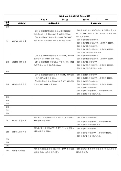
日立电梯NPH GVF2的FMT板操作说明MODE-0-SET 显示楼层MODE-1-SET 显示状态MODE-2-SET 故障码读取MODE-3-SET 机房检修MODE-4-SET 故障清除MODE-11-SET 层高测试GVF GH98 GVF2 NPH的故障码说明E10—E27 A1 停止电梯所有运作功能(*1)E30—E47 A2 停止电梯所有快、慢车运行功能(*2)E50—E57 B1 停止电梯快车、部分慢车运行功能(*3)E60—E67 B2 停止电梯快车运行功能(*4)E70—E77 C2 使电梯运行至最近指令层停车,然后按A2级故障方式处理E80—E87 E 对故障不作处理备注:(1)当电梯同时出现2个以上的故障时,故障的处理级别按高的进行。
(2)当电梯发生A、B类故障时,软件回路安全继电器#50X、运行接触器#10T和抱闸接触器#15B立即释放,电梯数字显示立即熄灭。
如果电梯发生故障是A2、B1或B2级时,软件回路安全继电器#50X在释放3秒钟后会再次吸合,这时电梯数字显示也恢复正常。
(3)在电梯的这6种级别的故障中,其中A1级故障是具有自动保持性质的。
也就是说当使电梯发生A1级故障的原因被排除或消除后,会继续保持A1级的处理状态,不会自动解除故障状态重新投入正常运行。
而其它级别的故障在故障条件排除或消除后,可以自动使电梯恢复正常运行状态。
*1.当A1级故障条件成立时,FMT微机使电梯进入A1级故障处理的状态—停止电梯所有运作功能。
所停止运作功能包括:电梯快车运行方式、慢车运行方式、电梯开关门功能、电梯显示等功能。
*2.A2级故障处理时,电梯停止快、慢车运行方式,但如果电梯是在门区位置时,可以开门。
*3.B1级故障处理时,电梯停止快车运行方式,只能作自救的慢车运行方式。
*4.B2级故障处理时,电梯停止快车运行方式,可作任何慢车运行方式。
E11 #10T ON、OFF故障E12 #15B ON、OFF故障E14 #97输入信号异常E21 #11输入信号异常E22 #12输入信号异常E26 规格表和数出错E27 重复故障检出E31 #100R输入信号异常E32 门区感应器故障E33 变频器异常运行E35 厅门、轿门动作不一致E36 变频器运行故障E37 电梯逆转故障E40 零速不一致E41 电梯低速超速故障E42 软安全回路继电器ON、OFF故障E43 变频器控制回路失电故障E44 #11动作超时故障E45 #12动作超时故障E46 速度低故障E50 高速超速故障E51 起动速度控制异常E52 瞬时停电故障E53 运行速度偏差故障E55 中速超速故障E56 微动平层超速故障E57 微动平层运行距离异常E60 电梯层高表和数出错E61 电梯同步位置出错E62 电梯层楼位置出错E63 电梯端站位置出错E64 电梯端站减速控制异常E70 变频器故障报警检出E71 变频门机故障E73 门区运行故障E75 通讯检出故障E76 电梯爬行时间异常E77 自救检出故障E80 电梯运行中断门锁检出E81 电梯检修状态异常E82 电梯微动平层超时故障E83 电梯安全回路故障检出E84 微动平层起动故障E85 变频器速度一致信号异常E86 电梯开门超时故障E87 电梯关门超时故障。
•Single-phase Input 200V Class •Three-phase Input 200V Class •Three-phase Input400V ClassManual No. NB5412XD • Dec. 2003Hitachi Industrial Equipment Systems Co., Ltd.HITACHIL100 Series Inverter Quick Reference GuideCaution: Be sure to read the L100 Inverter Manual andfollow its Cautions and Warnings for the initial productinstallation. This Quick Reference Guide is intended forreference use by experienced users in servicing existinginstallations.Power Circuit Terminals–002NFE/NFU, –004NFE/NFU, –005NFEJumper+1L1L2N/L3U/T1V/T2W/T3ChassisGround–007 to 022NFE/NFU, –037LFU, 004 to 040HFE/HFUJumper+1L1L2N/L3U/T1V/T2W/T3ChassisGround–055LFU, –075LFU, 055HFE/HFU, 075HFE/HFU Jumper+1L1L2N/L3U/T1V/T2W/T3ChassisGroundControl Circuit TerminalsTerminalName Description Ratings and NotesP24+24V for logic inputs24VDC supply, 30 mA max.(Notes: Do not use for network powerDo not short to terminal L)1, 2, 3, 4, 5Intelligent (program-mable) discrete logicinputs 27VDC max. (use P24 or an external supply referenced to terminal L), 4.7k Ω input impedance11, 12Discrete logic outputs 50 mA max. ON current,27 VDC max. OFF voltage L (top row)GND for logic inputs Sum of input 1 to 5 currents (Note: Do not ground)CM2Common for logic outputs 100 mA max for sum of terminals 11 and 12 currents FMPWM output0 to 10VDC, 1 mA max., 50% duty cycle L (bottom row)Common for analog inputs Sum of OI, O, and H currents (return)OIAnalog input, current4 to 19.6 mA range, 20 mA nominalH O OI FM P24L Analog inputsAnalog outputsAlarm relayLogic outputsLogic inputsL 54321CM21211AL0AL1AL2OAnalog input, voltage0 to 9.6 VDC range, 10VDC nominal, 12VDC max., input impedance 10 k ΩH +10V analog reference 10VDC nominal, 10 mAmax.AL0Relay common contact Contact rating Max resistive load = 250V AC, 2.5A; 30VDC 3A;Max inductive load = 250V AC, 0.2A; 30VDC 0.7AMinimum load = 5VDC 100mA,100V AC, 10mAAL1Relay contact, normally closed during RUN AL2Relay contact,normally open during RUNTerminal NameDescription Ratings and NotesBasic Wiring DiagramThe following wiring diagram shows the power and motor connec-tions for basic operation. The optional signal input wiring supports external Fwd and Rev Run command, and a speed potentiometer.(L1)R (L2)S (N/L3)T(T2)V(T3)W(T1)U MotorForwardLOHReverseAlarm contacts, 1 Form CRun signalFrequency arrival signal Open collector outputs:External speed reference pot.L100From 3-phase power input source (See specifications label on inverter for details)Logic output commonLoadLoadAnalog common Analog referenceP2421CM21211AL0AL1AL2Inputs:Inverter Keypad Operation•Run/Stop LED – ON when the inverter output is ON and the motor is developing torque, and OFF when the inverter output is OFF (Stop Mode).•Program/Monitor LED – ON when the inverter is ready for parameter editing (Program Mode). It is OFF when the parameter display is monitoring data (Monitor Mode).•Run Key Enable LED – ON when the inverter is ready to respond to the Run key, OFF when the Run key is disabled.•Run Key – Press this key to run the motor (the Run Enable LED must be ON first). Parameter F_04, Keypad Run Key Routing, determines whether the Run key generates a Run FWD or Run REV command.•Stop/Reset Key – Press this key to stop the motor when it is running (uses the programmed deceleration rate). This key will also reset an alarm which has tripped.(continued, next page...)Hz POWER ARUN PRGMINMAXHITACHIFUNC.STR1250.0Parameter Display Run/Stop LEDProgram/Monitor LEDRun Key Enable LEDRun Key Power LEDDisplay Units LEDs Hertz AmperesPotentiometer Enable LED Potentiometer Stop/Reset KeyFunction KeyUp/Down Keys Store Key•Potentiometer – Allows an operator to directly set the motor speed when the potentiometer is enabled for output frequency control.•Potentiometer Enable LED – ON when the potentiometer is enabled for value entry.•Parameter Display – A 4-digit, 7-segment display for parame-ters and function codes.•Display Units: Hertz/Amperes – One of these LEDs will be ON to indicate the units associated with the parameter display.•Power LED – ON when the power input to the inverter is ON.•Function Key – This key is used to navigate through the lists of parameters and functions for setting and monitoring parameter values.•Up/Down Keys – Use these keys alternately to move up or down the lists of parameter and functions shown in the display, and to increment/decrement values.•Store Key – When the unit is in Program Mode and the operator has edited a parameter value, press the Store key to write the new value to the EEPROM.Keypad Navigation Mapc 91c 0112b 89b 0112A 98A 0112121212C ––12b ––12A ––F 04F 0112d 09d 0112o.0123.4Edit12Increment/decrement valueWrite datato EEPROMDisplay dataMonitor Mode Program ModeFUNC.STRFUNC.FUNC.12Return to parameter listFUNC.FUNC.Store as powerup defaultpowerdownSelect ParameterEdit ParameterPowerup TestThe Powerup Test procedure uses minimal parameter settings to run the motor. The procedure describes two alternative methods for commanding the inverter: via the inverter keypad, or via the logic terminals.•Check power input and motor output wiring (see page4 diagram).•If using logic terminals for testing, verify correct wiring on [P24], [FW], [H], [O], and [L] (bottom row) per the diagram on page4.•Reverse [RV] input wiring (defaults to terminal [2]) is optional.Step Description Via Keypad Via LogicTerminals1Set speed command source setting A_01 = 00(keypad pot.)A_01 = 01,[H–O–L] input2Set Run FW command source A_02 = 02(Run key)A_02 = 01,[FW] input3Set Run REV command source —C_02 = 01,[RV] input4Set motor base freq.A_03 = 605Set keypad display to monitor freq.Access D_01, press Func key, display will show 0.0Perform safety check Disconnect load from motor6Turn keypad pot.to MIN position Ensure voltage on [O]—[L] termi-nals= 0V7Run Forward command Press Run key Turn ON the[FW] terminal8Increase speed Rotate keypadpot. CW dir.Increase voltage at [O]9Decrease speed Rotate keypadpot. CCW dir.Decrease voltage at [O]10Stop motor Press Stop key Turn OFF the[FW] terminal11Run Reverse command (optional)—Turn ON the [RV]terminal12Stop motor—Turn OFF the[RV] terminalError CodesThe L100 series inverters will trip on over-current, over-voltage, and under-voltage to protect the inverter. The motor output turns OFF, allowing the motor to free-run to a stop. Press the Stop/Reset key to reset the inverter and clear the error.Basic Error CodesErrorCode Name Probable Cause(s)E01Over current event whileat constant speed •Inverter output was short-circuited •Motor shaft is locked•Load is too heavy•A dual-voltage motor is wired incorrectlyNote: The L100 will over current trip at nominally 200% of rated currentE02Over current event duringdecelerationE03Over current event duringaccelerationE04Over current event forother conditions •DC braking power(A_54) set too high•Current transformer / noise errorE05Overload protection•Motor overload is detected by theelectronic thermal functionE07Over voltage protection•DC bus voltage exceeds a threshold,due to regenerative energy from motor E08EEPROM error•Built-in EEPROM memory experi-enced noise, high temperature, etc. E09Under-voltage error•DC bus voltage decreased enough tocause a control circuit faultE11E22CPU error•Built-in CPU had internal errorE12External trip•[EXT] input signal detectedE13USP (Unattended StartProtection)•When (USP) was enabled, an error occurred when power was applied while a Run signal was presentE14Ground fault•A ground fault was detectedbetween the inverter output and themotor. This feature protects theinverter, and does not protect humans. E15Input over-voltage•Input voltage was higher than thespecified value, 60 sec. after powerup E21Inverter thermal trip•Inverter internal temperature isabove the thresholdError Trip ConditionsUse function code D_08 to access the error trip conditions for the current error as shown in the table below. Use the Up and Down arrow keys to scroll through the trip condition parameters.E35Thermistor•Thermistor input, [THM] and [L], is over the temp. threshold---Under-voltage (brown-out) with output shutoff•Low input voltage caused theinverter to turn OFF the motor output and try to restart. If unsuccessful, a trip occurs.StepDisplay1. Access D_08d 082. Press Function KeyIf no error:_ _ _If error exists:Exx(error code)3. Press Up/Dn key (if error exists)Output frequency at trip point:10.0Motor current at trip point:0.025DC bus voltage at trip point:189.8Error CodeNameProbable Cause(s)12Restoring Factory Default SettingsActionDisplayFunction/ParameterPress ,or as needed.b --“B” Group selectedPress .b 01First “B” Group parame-terPress/holduntil...b 85Country code forinitialization selected Press . If setting iscorrect, then skip next step.0200 = Japan 01 = Europe02 = United StatesTo change country code, press or to set; to store.Press .b 85Country code forinitialization selected Press .b 84Initialization function selectedPress .000 = disable initialization, clear trip history only Press .011 = enable initialization Press .b 84Initialization now enabled to restore all defaultsPress/hold , ,and . Do not release yet.b 84First part of key sequencePress/hold (STOP)for 3 seconds, then release.d 00Final part of special sequence, “D_00” is flashingNow release the all keys together, only after “D_00” display begins blinking.EU USA JP Default parameter country code shown during initializationInitialization is complete.d 01Function code for output frequency monitor shownFUNC.12FUNC.1FUNC.12STR FUNC.2FUNC.1STR FUNC.12Note: After initializing the inverter, use the Powerup Test on page 8 to get the motor running again.Parameter Tables“D” Group: Monitoring FunctionsFunc. Code Name / DescriptionUnits D_01Output frequency monitor Hz D_02Output current monitor A D_03Rotation direction monitor—D_04Process variable (PV), PID feedback monitor %D_05Intelligent input terminal status—D_06Intelligent output terminal status—D_07Scaled output frequency monitor(output frequency x B_86 scale factor)User-defined D_08Trip event monitor —D_09Trip history monitor—DirectionForward Stop Reverse21435Terminal NumbersON OFF1211AL Terminal NumbersON OFFTrip History Navigation MapE 0760.0124.00270.01212d 0812o.00Display dataMonitor Mode12FUNC.FUNC.d 09____NoError code Output frequency at trip point Motor current at trip point DC bus voltage at trip pointFUNC.Y esNo errorError (n-1) exists?NoY esE 03E 05____No historyFUNC.Error (n-2) exists?NoY esFUNC.____FUNC.FUNC.12FUNC.No historyError exists?Parameter tables for user-settable functions follow these conven-tions:•Some parameters specify an option code. Where applicable, the options codes will be in a bulleted list in the Name/Description column.•The default values apply to all models unless otherwise noted for each parameter... –FE (Europe) / – FU (U.S.) / –FR (Japan).•Some parameters cannot be edited during Run Mode, and certain Software Lock settings (B_31) can prohibit all edits. If in doubt, place the inverter in Stop Mode or consult the inverter manual for details.“F” Group: Main Profile ParametersFunc.Code Name / Description DefaultValueSetValueF_01Output frequency setting0.0 F_02Acceleration (1) time setting10.0 F_03Deceleration (1) time setting10.0 F_04Keypad Run key routing•00Forward•01Reverse00“A” Group: Standard FunctionsFunc.Code Name / DescriptionDefaultValue–FE / –FU /–FRSetValueA_01Frequency source setting•00Keypad potentiometer•01Control terminal•02Function F_01 setting01 / 01 / 00A_02Run command source setting•01Input terminal FW or RV (assign-able)•02Run key on keypad, or digitaloperator01 / 01 / 02A_03Base frequency setting50.0 / 60.0 /60.0A_04Maximum frequency setting50.0 / 60.0 /60.0A_11O/OI–L input active range startfrequency0.0A_12O/OI–L input active range end frequency0.0A_13O/OI–L input active range start voltage0A_14O/OI–L input active range end voltage100A_15O/OI–L input start frequency enable•00Use A_11 starting value)•01Use 0 Hz01A_16External frequency filter time constant8A_20Multi-speed frequency setting0A_21 A_22 A_23 A_24 A_25 A_26 A_27 A_28 A_29.. ..A_35Multi-speed frequency settings0 / 0 / 50 / 0 / 100 / 0 / 150 / 0 / 200 / 0 / 300 / 0 / 400 / 0 / 500 / 0 / 600 / 0 / 0A_38Jog frequency setting 1.0 A_39Jog stop mode•00Free-run stop, jogging disabledduring motor run•01Controlled deceleration, joggingdisabled during motor run•02DC braking to stop, joggingdisabled during motor run00A_41Torque boost method selection•00Manual torque boost•01Automatic torque boost00A_42Manual torque boost value11 A_43Manual torque boost frequency adjust-ment10.0A_44V/f characteristic curve selection•00V/f constant torque•01V/f variable torque00A_45V/f gain setting100 A_51DC braking enable•00Disable•01Enable00 A_52DC braking frequency setting0.5 A_53DC braking wait time0.0 A_54DC braking force during deceleration0 A_55DC braking time for deceleration0.0 A_61Frequency upper limit setting0.0 A_62Frequency lower limit setting0.0 A_63A_65A_67Jump (center) frequency setting0.0A_64 A_66 A_68Jump (hysteresis) frequency widthsetting0.5A_71PID Enable•00PID operation OFF•01PID operation ON00A_72PID proportional gain 1.0A_73PID integral time constant 1.0A_74PID derivative time constant0.0A_75PV scale conversion 1.00A_76PV source setting•00[OI] terminal (current input)•01[O] terminal (voltage input)00A_81A VR function select•00A VR enabled•01A VR disabled•02A VR enabled except during decel02 / 00 / 02“B” Group: Fine-tuning FunctionsA_82A VR voltage select 230/230/200400/460/400A_92Acceleration (2) time setting 15.0A_93Deceleration (2) time setting15.0A_94Select method to switch to Acc2/Dec2 profile•002CH input from terminal •01transition frequency00A_95Acc1 to Acc2 frequency transition point 0.0A_96Dec1 to Dec2 frequency transition point 0.0A_97Acceleration curve selection •00Linear •01S-curve 00A_98Deceleration curve selection •00Linear •01S-curve00Func. Code Name / DescriptionDefault Value –FE / –FU /–FRSet ValueB_01Selection of automatic restart mode •00Alarm output after trip, automatic restart disabled •01Restart at 0Hz•02Resume operation after frequency matching•03Resume previous freq. after freq. matching, then decelerate to stop and display trip info00B_02Allowable under-voltage power failure time1.0B_03Retry wait time before motor restart1.0B_12Level of electronic thermal setting Ratedcurrent ofeach inverter B_13Electronic thermal characteristic•00Reduced torque•01Const. torque01 / 01 / 00B_21Overload restriction operation mode•00Disabled•01Enabled for accel and constantspeed•02Enabled for constant speed only01B_22Overload restriction setting Ratedcurrentx 1.25B_23Deceleration rate at overload restriction 1.0B_31Software lock mode selection•00Low-level access, [SFT] blocksedits•01Low-level access, [SFT] blocksedits (except F_01 and Multi-speedparameters)•02No access to edits•03No access to edits except F_01 andMulti-speed parameters01B_32Reactive current settingNote: For Japanese (–FR) versions, only–055LFR, –055HFR, –075LFR, and–075HFR models support this function.58% rated currentB_81[FM] terminal analog meter adjustment80B_82Start frequency adjustment0.5B_83Carrier frequency setting 5.0 / 5.0 /12.0B_84Initialization mode (parameters or triphistory)•00Trip history clear•01Parameter initialization00B_85Country code for initialization•00Japan version•01Europeversion•02US version01 / 02 / 00B_86Frequency scaling conversion factor 1.0B_87STOP key enable•00Enable•01Disable00“C” Group: Intelligent Terminal FunctionsB_88Restart mode after FRS •00Restart from 0Hz•01Restart from frequency detected from actual speed of motor00B_89Data select for digital operator OPE-J •01Output frequency (D_01)•02Output current (D_02)•03Motor direction (D_03)•04PID PV feedback (D_04)•05Input states for input terminals (D_05)•06Output states for output terminals (D_06)•07Scaled output frequency (D_07)01Func. Code Name / DescriptionDefault Value –FE / –FU /–FRSet ValueC_01Terminal [1] function Fifteen option codes available (see page 21)00C_02Terminal [2] function 01C_03Terminal [3] function 02 / 16 / 02C_04Terminal [4] function 03 / 13 / 03C_05Terminal [5] function 18C_11Terminal [1] active state•00Normally open [NO]•01Normally closed [NC]00C_12Terminal [2] active state00C_13Terminal [3] active state00C_14Terminal [4] active state00 / 01 / 00C_15Terminal [5] active state00C_21Terminal [11] function Six optioncodes available(see page22)01C_22Terminal [12] function00 C_23[FM] signal selection Three optioncodes available(see page22)00C_31Terminal [11] activestate (–FU)•00Normallyopen (NO)•01Normallyclosed (NC)— / 00 / —Reserved (–FE / –FR)00 / — / 00 C_32Terminal [12] activestate (–FU)— / 00 / —Terminal [11] activestate (–FE / –FR)00 / — / 00C_33Alarm relay terminalactive state01C_41Overload level setting Ratedcurrent ofeach inverter C_42Frequency arrival setting for accel0.0C_43Arrival frequency setting for decel0.0C_44PID deviation level setting 3.0C_91Debug mode enable•00Display•01No display 00Func.Code Name / DescriptionDefaultValue–FE / –FU /–FRSetValueIntelligent Input Terminal ListingSymbol Code Input Terminal NameFWD00Forward Run/StopRV01Reverse Run/StopCF102Multi-speed select, Bit 0 (LSB)CF203Multi-speed select, Bit 1CF304Multi-speed select, Bit 2CF405Multi-speed select, Bit 3 (LSB)JG06Jogging2CH092-stage accel and decelFRS11Free-run stopEXT12External tripUSP13Unattended start protectionSFT15Software lockAT16Analog input voltage/current sel.RS18Reset inverterPTC19PTC thermistor thermal protectionIntelligent Output Terminal ListingAnalog Input ConfigurationThe following tables show the parameter settings required for vari-ous analog input signal types.Analog Output Function ListingThe following table shows all three functions available for assign-ment to the analog output terminal:•Terminal [FM], option set by C_23Symbol Code Input Terminal NameRUN 00Run signalFA101Freq. arrival type 1 – constant speed FA202Freq. arrival type 2 – over-frequency OL 03Overload advance notice signal OD 04Output deviation for PID control AL05Alarm signal[AT]External Frequency Command InputOFF [O] — [L]ON[OI] — [L](not assigned to any inputterminal)Summation of [O] — [L] and [OI] — [L]Option Code Function Name Description Corresponding Signal Range 00Output frequency Actual motor speed, represented by PWM signal0 to max. freq. in Hz01Output currentMotor current (% of maximum rated output current), represented by PWM signal0 to 200%02Digital output frequencyOutput frequency 0 to max. freq. in HzNotes:。
前言
新开发的NPH-Ⅱ电梯是在NPH电梯基础上进行修改设计的,采用富士变频器HLI、富士SC-N4/SE直流DC48V接触器,SCLA4板、SCLB2板等新器件。
由于该梯种的微机FMT、SCL串行通讯系统等电气部分和机械系统部分都和NPH电梯类似,不影响电梯的调试,只有电气部分的变频器由富士H7变频器变成了富士专门为电梯开发的专用变频器HLI,故对于NPH-Ⅱ电梯将不出调试手册。
与NPH电梯类似部分的操作请参考NPH电梯调试手册或相关作业指引,本工艺只对变频器HLI的使用操作进行详细说明。
如作业人员对该作业指引有改进意见,请反馈回工程本部技术开发科。
编者
2006年8月
图1-1图1-2
图2-1 1.2 按键功能说明
功能
变频器和键盘外形(图2-2)
图2-2
电梯出厂时键盘不安装于变频器上。
需要使用时,可以将键盘通过延伸电缆
与变频器连接,握于手中进行操作,也可以直接安装于变频器键盘小室上。
利用延伸电缆的安装方法(建议使用此方法,在操作过程中稳健可靠)延伸电缆的一端插于键盘的连接器上,另一端插在原键盘小室的连接端口上。
插入后,应再检查和确认,是否可靠插好,方可通电。
图
RJ-45连接器
(组合插座)
远程操作用延长电缆
(CB-5S,CB-3S,CB-1S)
或LAN电缆
多功能操作面板
连接器
的方法一样。
图2-4
3、键盘使用方法
将键盘连接到变频器后,通电,键盘显示主界面,提示按
树脂部分
图3-1。