施耐德万高D型控制器使用说明
- 格式:doc
- 大小:417.00 KB
- 文档页数:11
D 型控制器 用户手册施耐德万高()电气设备Schneider Wingoal (Tianjin) Electric Equipment Co., Ltd● 控制器功能介绍● 控制器安装及接线说明 ● 控制器设置操作 ●附录1 通讯协议下面的符号将用于本手册的说明,提醒您注意潜在的危险,或者请您注意那些阐述、简化过程和关键操作。
:安全警示标志,提示您如果违规操作可能造成人身安全危险或本开关的不可恢复性损坏。
: 关键性操作,提示您使用不当时,可能使控制器工作于非正常状态。
:提供另外的信息或简化的操作方法。
请注意:电气设备应该让有资格的专业人员进行安装、操作、使用、维护。
未按使用手册操作而造成的不良后果,施耐德电气公司将不负任何责任。
控制器功能介绍本控制器工作电压为AC380V,工作频率为50Hz,主要功能是进行电压采集,根据电压的实时值进行故障判断(三相断相、欠压、过压和失压),并控制转换开关进行相应的转换动作。
用户还可根据实际需要选配电流模块实现实时电流、有功功率和有功电能的显示。
另外,控制器提供多组无源节点的输入和输出,包括故障输出、负荷卸载、发电机启动、动作无源输出、远程投备(无源输入)、消防联动(无源输入)以及通讯接口,具体接线参见第2.2节。
控制器安装及接线说明1.1.控制器外形尺寸图1 D型控制器外形尺寸1.2. 控制器二次接线1.2.1. 控制器端子说明1.2.2. A1-A3备A4-D2,A5-RJ,A6-OUT,A7-D3,A8-D1,A9-NJ,A10-12,主 A2A3A4A5A6A7A8A9A10A11A12OUTB1B2B3B4B5B6B7B8B9B10B11B12故障输出负荷卸载主转备备转主发电机启动C1C2C3C4C5C6C7C8C9C10空D3NBRB空远程投备消防联动D1D2D3D4D5D6D7D8D9D10D11D12ABA`B`G空IC*IB*IA*动作输出RS485IC IB IA☐动作输出:当机构中电机转动时,常开触点闭合; ☐ 故障输出:当常用或备用电源故障时,常开触点闭合;☐ 负荷卸载:在电网-发电机模式下,常用电源故障,常开触点闭合;☐发电机启动:在电网-发电机模式下,常用电源正常,常开触点闭合,常用电源故障,常开触点打开;☐ RS485:通信用端口,A’ B’为通信预留端口;☐ IA~IC :电流互感器输入端口I*为输入端,I 为输出端;(输入额定电流5A ) ☐ 远程投备(无源):短接此两点,机构转到备用位置,开关状态主分备合;(可靠距离10m) ☐ 消防联动(无源):短接此两点,机构转到双分位置,开关状态主分备分;(可靠距离10m,WTS-D800~5000系列不具备该项功能): 控制器的发电机启动端子在常用电源正常时常闭触点断开,当常用电源故障时常闭触点闭合以接通发电机启动电路;常开触点与之相反,请用户注意。
ATMT自动电源转换系统用户手册下面的符号将用于本手册的说明,提醒您注意潜在的危险,或者请您注意那些阐述、简化过程和关键操作。
开关的不可恢复性损坏。
X: 关键性操作,提示您使用不当时,可能使控制器工作于非正常状态。
请注意:电气设备应该让有资格的专业人员进行安装、操作、使用、维护。
未按使用手册操作而造成的不良后果,施耐德电气公司将不负任何责任。
目录一、控制器介绍 (1)1. 符合标准 (1)2. 污染等级 (1)3. 抗湿热等级 (1)4. 电磁兼容性 (1)5. 安装与操作指南 (1)6. 安全信息 (1)7. 控制器类型 (1)二、控制器操作及参数设置 (3)1. 2A/2B控制器面板介绍 (3)2. 3A/3B控制器面板介绍 (4)3. 显示及设置 (5)三、控制器端子说明 (11)四、安装及接线 (12)1. 控制器外形及安装尺寸 (12)2. 适配器外形及安装尺寸 (13)3. 适配器与开关接线图 (15)4. 2A/2B整体安装图 (16)5. 3A/3B整体安装图 (17)一、控制器介绍1.符合标准•GB14048.1-2006 低压开关设备和控制设备:总则•GB14048. 2-2008 低压开关设备和控制设备:断路器•GB/T14048.11-2008 低压开关设备和控制设备:多功能电器转换开关电器•IEC60947:2005 Low-voltage switchgear and controlgear•IEC60947-2:2005 Low-voltage switchgear and controlgear: Breakers•IEC60947-6-1:2005 Low-voltage switchgear and controlgear: Multiple function equipment- Transfer switching equipment2.污染等级•Level33.抗湿热等级A TMT已通过下列标准所规定的严格环境条件下的试验•IEC60068-2-1 干冷环境(-5℃)•IEC60068-2-1 干热环境(+40℃)•IEC60068-2 低温4.电磁兼容性•辐射等级B级执行标准GB4824(CISPR11)•静电放电空气放电Level3;接触放电Level2 执行标准GB1 7626.2-2006(IEC61000-4-2)•射频电磁场LE VEL3 执行标准GB1 7626. 3-2006 (IEC61000-4-3)和GB1 7626.6-2006 (IEC61000-4-6)•电快速瞬变脉冲群LE VEL3 执行标准GB1 7626.4-2008 (IEC61000-4-4)•浪涌LE VEL3 执行标准GB1 7626. 5-2008 (IEC61000-4-5)5.安装与操作指南即使控制单元处于待机状态,在手动操作断路器前需要将其断电,它可能在没有任何警告的情况下操作断路器。
施耐德控制器安全操作及保养规程施耐德控制器是一种重要的工业设备,它在自动化生产中起着至关重要的作用。
然而,由于操作不当或者缺乏保养可能会造成设备损坏或者安全事故的风险。
因此,需要遵循一定的操作规程和保养规程,来确保设备的安全、高效运行。
一、施耐德控制器的操作规程1.1 施耐德控制器的基本结构施耐德控制器主要由控制器、输入模块和输出模块三部分组成。
控制器负责数据处理和控制运行,输入模块用于输入控制命令,输出模块用于输出电信号。
通常还会配备相应的软件和接口,以便于用户进行程序编辑和管理。
1.2 施耐德控制器的操作步骤(1) 开启控制器电源,待指示灯亮起后即可开始操作。
(2) 按照需要编辑控制程序。
用户可以通过控制器配备的编辑软件,对控制程序进行编辑、调整。
(3) 输入控制命令。
控制命令一般通过输入模块完成。
(4) 开始运行控制程序。
运行指令可以通过控制器的软件进行操作或者通过控制面板上的启动按钮进行操作。
(5) 观察控制器的运行状态,如果出现异常或者错误提示,及时进行处理。
1.3 施耐德控制器的注意事项(1) 在使用控制器前,必须了解控制器的功能和特点,并按照说明书操作。
(2) 避免超负荷或者频繁开关导致设备过热或者故障。
(3) 严禁在控制器运行时随意拔下连接线,或者未经授权更改控制程序。
(4) 在进行硬件接线时,必须按照图纸或者说明书要求进行接线,避免接线错误导致设备损坏或者人身安全事故。
二、施耐德控制器的保养规程2.1 施耐德控制器的保养周期施耐德控制器通常需要进行定期保养,以确保设备的正常运行和延长设备的使用寿命。
保养周期根据设备类型和使用环境的不同而不同,一般建议每季度对设备进行一次保养。
2.2 施耐德控制器的保养内容(1) 清洁内部部件。
使用吸尘器或者干净的布擦拭,去除尘土和杂物,避免影响设备散热性能。
(2) 检查连接线和插头。
检查连接线是否牢固,插头是否松动、腐蚀,必要时更换连接线和插头。
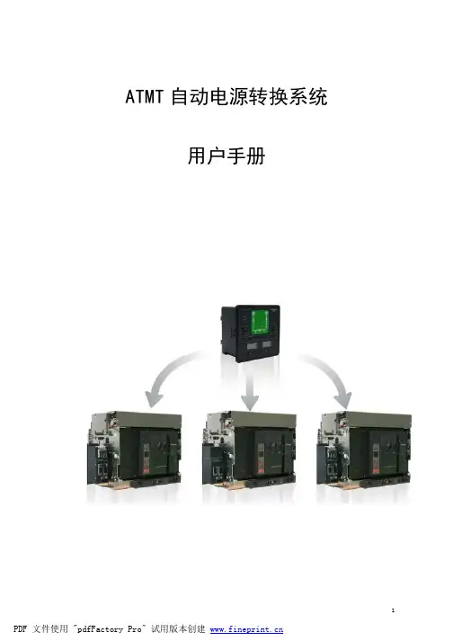
一、概述本控制器用于控制电动转换开关、接触器、电动操作空气开关,实现双电源自动切换。
该控制器采用微机技术,AD数据采集,可同时监测两路三相电源的过压、欠压、断相。
液晶显示器可实时显示测量电压值及各种状态信息。
该控制器对所有系统参数及可选控制功能均可通过中文液晶设置菜单进行现场设置及更改, 485通讯接口,可实现三遥功能。
为满足现场要求控制器可实现自动返回、故障返回、复位返回三种切换方式,也可选择电源I或电源II为首选电源及市电-市电、市电-油机切换。
二、电气性能及功能1工作电源:交流型:AC230V(±20%),50HZ2 环境温度: -10°C~70°C3 电源Ⅰ/电源Ⅱ电压检测•单相或三相 AC230V/380V•±1%精度4 可任意选电源I或电源II为首选电源5.可选择自动返回(自投自复)、故障返回(互为备用)、复位返回(自投不自复)6.可选择控制器为市电/市电或市电/油机工作模式7 火灾报警信号联动---转换到零位(DC24V输入)8.过流跳闸自动报警9.转换开关位置信号采集(有源AC110-280V)10.可编程输出: 负载在电源Ⅰ负载在电源Ⅱ电源Ⅰ正常电源Ⅱ正常双电源正常启动油机( 230V 5A )11 转换控制输出•转换位置Ⅰ输出 ( 常开230V 5A )•切换位置Ⅱ输出 ( 常开230V 5A )•切换位置0输出 ( 常开230V 5A )12.RS232/485通讯接口•可遥控、遥测、遥信13.转换延迟--由位置I转到位置II的延迟0-255秒14.返回延迟--由位置II转到位置I的延迟0-255秒15.冷机延迟--在市电/油机模式开关返回到位置I后停止油机运行延迟0-255秒16.转换到中间位延迟0-11秒注:若将可编程输出设置成(启动油机)则控制器为市电/油机工作模式三、操作及显示液晶屏自动循环显示如下内容第一行第二行第一行显示内容•电源I正常•电源II正常•电源I故障•电源II故障•自动工作方式•手动---位置I•手动---位置II•手动---位置O•遥控---位置I•遥控---位置II•位置II >位置I•位置I >位置II•跳闸或接线故障--------开关过流跳闸或位置返馈线联接错误•火警联动-----------------接收到火警联动信号•转换延迟XXX秒-----主电源转换到备用电源的延迟•返回延迟XXX秒-----备电源转换到主电源的延迟•冷机延迟XXX秒-----油机/市电工作模式,转换开关返回到市电取消启动油机信号注. 当电源I或电源II失电时转换到位置O功能无效第二行显示内容•第一路相电压/线电压 PI XXXV XXXV XXXV•第二路相电压/线电压 PII XXXV XXXV XXXV•电源I断相•电源II断相四、控制器遥测-遥信-遥控功能通过计算机通讯接口可进行远端遥控及电量采集。

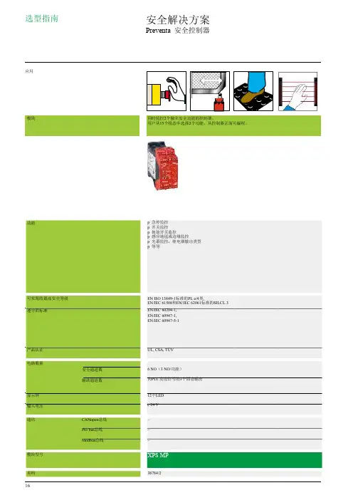
选型指南应用模块功能 可实现的最高安全等级遵守的标准产品认证电路数量显示屏输入电压 安全通道数辅助通道数 安全解决方案 Preventa 安全控制器 同时监控2个独立安全功能的控制器。
用户从15个组态中选择2个功能,从控制器正面可编程。
p 急停监控 p 开关监控 p 使能开关监控 p 感应地毯或边缘监控 p 光幕监控,继电器输出类型 p 等等 EN ISO 13849-1标准的PL e/4类, EN/IEC 61508和EN/IEC 62061标准的SILCL 3 EN/IEC 60204-1, EN/IEC 60947-1, EN/IEC 60947-5-1 UL, CSA, TÜV 6 NO (3 NO/功能) 向PLC 发送信号的3个固态输出 12个LED c 24 V通讯 CANopen 总线– 模块型号页码 16 Pro bus 总线Modbus 总线– – XPS MP38784/2可以使用软件组态的控制器,用于多个独立的安全功能:使用在Windows 上运行的组态软件选择安全功能(16或32个输入和8个独立安全输出)p 急停监控p 限位开关监控p 双手控制监控p 安全光幕监控,带/不带“静音”功能p 使能开关监控,编码磁开关监控p 安全地毯监控p 液压机电磁阀监控p 偏心压机的上死点的安全停止器监控。
零转速检测 p 液压机监控p 偏心压机监控p 脚踏开关监控p 链轴断裂监控p 安全工具p 位置选择器EN ISO 13849-1标准的PL e/4类,EN/IEC 61508和EN/IEC 62061标准的SILCL 3EN/IEC 60204-1,EN 1760-1/ISO 13856-1,EN/IEC 61496-1,EN 574/ISO 13851,EN/IEC 60947-1,EN/IEC 60947-5-1UL, CSA, TÜV4 NO (2 NO/功能)+ 6固态1个“静音”信号输出正面LED 显示屏c 24 V通过SUB-D 9芯针型连接器,仅用于XPS MC16ZC 和XPS MC32ZC 通过SUB-D 9芯孔型连接器,仅用于XPS MC16ZP 和XPS MC32ZP 通过RJ45连接器,用于所有控制器XPS MCppZpXPS MC38789/2 17。

Dual PID Control Temperature ControllerFeatures● Dual PID auto tuning function:High-speed response of PID control to reach to thedesired value fast, low-speed of response of PID control to minimize the overshoot even though response is a little bit slow.● High display accuracy: ±0.3% (by F .S. value of each input)● 2-step auto tuning control function ● M ulti-input function(13 kinds of multi-input selection function):Temperature sensor, voltage and current selection function.● Various sub output function:Includes in LBA, SBA, 7 kinds of alarm output and 4 kinds of alarm option function, PV transmission output (DC4-20mA), RS485 communication output ● Display the decimal point for analog input※ T he unit cannot be configured with any random combination from the above ordering information. Please refer to ' Specifications' for possible configurations. ※1: 11-pin sockets (PG-11, PS-11(N)) are sold separately.Comprehensive Device Management Program (DAQMaster)●DAQMaster is comprehensive device management program for convenient management of parameters and multiple device data monitoring.●Visit our website () to download user manual and comprehensive device management program.< DAQMaster screen >< Computer specification for using software >Item Minimum requirementsSystemIBM PC compatible computer with Intel Pentium Ⅲ or above Operating system Microsoft Windows 98/NT/XP/Vista/7/8/10Memory 256MB or moreHard disk More than 1GB of free hard disk space VGA 1024×768 or higher resolution display OthersRS-232 serial port (9-pin), USB portTZ4SPTZN4STZ4STTZ4M1A 1aSV2 IN Max.5VDC TC250VAC 1A 1a250㎂PV OUT DC4-20mATCTCTC※RTD: DPt100Ω (3-wire type), JPt100Ω (3-wire type)※TC (Thermocouple): K(CA), J(IC), R(PR), E(CR), T(CC), S(PR), N(NN), W(TT)※In case of analog input, please use TC (Thermocouple) terminal and be careful about polarity.TZ4SPTZ4STTZN4STZ4MDimensions(unit: mm)TZN4HTZ4LTZN4L(unit: mm)(unit: mm)Panel cut-out dimensionsSizeSeriesAB C D TZ4SP , TZ4ST, TZN4S Min. 55Min. 6245 045 0TZ4M Min. 74Min. 9168 068 0TZN4M Min. 91Min. 9168 068 0TZ4W, TZN4W Min. 112Min. 5092 045 0TZ4H, TZN4H Min. 50Min. 10245 092 0TZ4L, TZN4LMin. 98Min. 10692 092 0Temperature range (Temperature range ( KCaH-148KCaL Not supported JIcH32JIcL Not supported R PR32ECrH32ECrL Not supported TCcH-328TCcL Not supported S PR32NN32U TT32JPtH32JPtL-199.9DPtH32DPtL-199.9A--1-1999 to 9999A--2(display range will vary depending on the decimal point.) A--3Unit Description1. P resent value (PV) display (red):RUN mode: displays the current value (PV) Setting mode: displays parameters 2. S et value (SV) display (green):RUN mode: displays the set value (SV)Setting mode: displays parameter setting values3. SV2 operation indicator : turns ON when SV2 is operating4. Auto-tuning indicator : turns ON when auto-tuning5. Control output operation indicator : t urns ON when control output is ON. Does not operate when the control outputis current output.6. E vent output indicator : t urns ON when the according event output is ON.※The Event 2 output indicator does not operate in TZ4SP .7. Mode key : enter parameter group, return to RUN mode, switch parameters, save setting values8. Auto-tuning key : hold the key for 3 sec to start auto-tuning. Hold the key for 5 sec while auto-tuning to stop auto-tuning.9. Setting keysSV Setting13247※When changing the previous SV of 0℃ to 170℃,Configuring Input TypePlease configure the internal switches before supplying power. After supplying power, configure the input type [IN-T ] in parameter group 2 according to the input type.● Detaching the casePress the front case then pull the case to detach the case from the body.Configure the internal switches as input type.)key-Switch fields, , key-Change valueshe dotted line parameters may not appear depending on the model orEU-1, EU-2] is set to AL-0, LBA, SBA.※O nly appears in modelsthat support RS485communicationOFF UnlockON Lock parameter 2※R un auto-tuning during initial setup of the temperature controller.※I f the thermal characteristics of the control target devicehas changed after extended usage, re-run auto-tuning.Mode Name DescriptionAL-A Standard alarm Alarm output turns ON upon alarm condition, and alarm output turns OFF when condition is cleared.AL-B Alarm latch Alarm output turns ON and maintains ON upon alarm condition.AL-C StandbysequenceThe first alarm condition is ignored. It will operate as standard alarm from the second alarm condition. If it is underalarm condition when power is supplied, it will ignore the condition and operate as standard alarm from the nextalarm condition.AL-D Alarm latchand standbysequenceIt will operate as both alarm latch and standby sequence upon alarm condition. If it is under alarm condition whenpower is supplied, it will ignore the condition and operate as alarm latch from the next alarm condition.Alarm (event)Alarm output can be configured by combining alarm operation and alarm options. Set the alarm operation in event 1/2 [EU1, EU2] of parameter group 2, and set the alarm options in alarm option [AL-T ].H: Alarm output hysteresis[AHYS ]2) Alarm options4) Loop break Alarm (LBA)Diagnose control loop and transmit alarm output through temperature change of control target. During heating(cooling) control, the alarm output turns ON if the PV does not rise/drop by a specific amount (approx. 2℃) during LBA monitoring period [LBA ] while control output amount is at 100%(0%).※ I f the thermal response of the control target is slow, the LBA monitoring period [LBA ] of parameter group 1 should be set longer. ※ L BA only operates when the control output amount is 100%(0%) so it cannot be used in current output models.※ I f the alarm output turns ON after the sensor has been disconnected, the alarm output will not turn OFF even after reconnecting the sensor. To disengage the alarm output, the temperature controller power must be reset.3) Sensor break alarmAlarm output turns ON when sensor is not connected or loses its connection during temperature control. Sensordisconnection can be tested by connecting buzzers or other devices to the alarm output contact. Sensor break alarm output operates through EV1 OUT or EV2 OUT contacts. Alarm output is disengaged after resetting the power.Communication command and blockFormat of command and response① Start codeIt indicates the first of Block STX → [02H], in case of response, ACK will be added.② Address codeThis code is master system can discern TZ/TZN Series and able to set within range of 01 to 99. (BCD ASCII)③ Header codeIt indicates command as 2 alphabets as below.RX (Read request) → R [52H], X [58H]RD (Read response) → R [52H], D [44H]WX (Write request) → W [57H], R [58H]WD (Write response) → W [57H], D [44H]④ Text: It indicates the detail contents of command/ response. (see command)⑤ END code: It indicates the end of Block. ETX → [03H]⑥ BCC: It indicates XOR operating value from the first to ETX of the protocol as abbreviation of TZ/TZN.Communication command● Read [RX] of measurement/setting value: address 01, command RX mand (master)① CommandSTX 01RXPETX FSC StartAddressCommand headP:Process value S:Setting valueEndBCC② Application: address (01), header code (RX), process value (P)STX 01R X P 0ETX FSC 0230315258503003BCC● Write [WX] of setting value: address 01, command WX mand (master)① CommandSTX1WXSSymbol 103102101100ETX FSCStart Address Commandhead S:Setting valueSpace/-103102101100End BCC② Application: In case of writing address (01), headingcoad (WX), setting value (S) +123.STX 01W X S 0Symbol 103102101100ETX FSC 02303157585330203031323303BCCResponse● Read of process/Setting value1. In case of receiving normal process value:The data is transmitted adding ACK [60H].(In case process value is +123.4)A C K S T X 01R DP0Symbol 103102101100Decimal pointE T XF S C NULL A C KS T X01R D PSpace12341E T X B C C N U LL 060230315244503020313233343103B C C002. In case process value is -100A C KS T X1RDP-01E T XB C C N U L L 06023031524450302D 303130303003B C C00※It is responded with 1 byte sized NULL (00H) at the end of response frame (next BCC 16).● Write of setting valueIn case setting value is -100A C K S T X 01WDSSymbol 103102101100E T XF S C A C K S T X 01W D S 0-0100E T X B C C 06023031574453302D 3031303003B C C● Others: In case of no response of ACK① When the address is not the same after receiving STX.② When receiving buffer overflow is occurred.③ When the baud rate or others communication setting value are not the same.● When there are no ACK response① Check the status of lines② Check the communication condition (setting value)③ When assuming the problem is due to noise, try to operate communication 3 times more until recovery.④ When occurred communication failure frequently, please adjust the communicating speed.。

施耐德a t s D型控制器用户手册WEIHUA system office room 【WEIHUA 16H-WEIHUA WEIHUA8Q8-D型控制器用户手册●●●●施耐德万高(天津)电气设备有限公司Schneider Wingoal (Tianjin) Electric Equipment Co., Ltd下面的符号将用于本手册的说明,提醒您注意潜在的危险,或者请您注意那些阐述、简化过程和关键操作。
身安全危险或本开关的不可恢复性损坏。
: 关键性操作,提示您使用不当时,可能使控制器工作于非正常状态。
:提供另外的信息或简化的操作方法。
请注意:电气设备应该让有资格的专业人员进行安装、操作、使用、维护。
未按使用手册操作而造成的不良后果,施耐德电气公司将不负任何责任。
控制器功能介绍本控制器工作电压为AC380V,工作频率为50Hz,主要功能是进行电压采集,根据电压的实时值进行故障判断(三相断相、欠压、过压和失压),并控制转换开关进行相应的转换动作。
用户还可根据实际需要选配电流模块实现实时电流、有功功率和有功电能的显示。
另外,控制器提供多组无源节点的输入和输出,包括故障输出、负荷卸载、发电机启动、动作无源输出、远程投备(无源输入)、消防联动(无源输入)以及通讯接口,具体接线参见第节。
控制器安装及接线说明1.1.控制器外形尺寸图1 D型控制器外形尺寸1.2. 控制器二次接线1.2.1. 控制器端子说明1.2.2. A1-A3备A4-D2,A5-RJ,A6-OUT,A7-D3,A8-D1,A9-NJ,A10-12,主 A2A3A4A5A6A7A8A9A10A11A12OUTB1B2B3B4B5B6B7B8B9B10B11B12故障输出负荷卸载主转备备转主发电机启动C1C2C3C4C5C6C7C8C9C10空D3NBRB空远程投备消防联动D1D2D3D4D5D6D7D8D9D10D11D12ABA`B`G空IC*IB*IA*动作输出RS485IC IBIA☐动作输出:当机构中电机转动时,常开触点闭合; ☐ 故障输出:当常用或备用电源故障时,常开触点闭合;☐ 负荷卸载:在电网-发电机模式下,常用电源故障,常开触点闭合;☐发电机启动:在电网-发电机模式下,常用电源正常,常开触点闭合,常用电源故障,常开触点打开;☐ RS485:通信用端口,A’ B’为通信预留端口;☐ IA~IC :电流互感器输入端口I*为输入端,I 为输出端;(输入额定电流5A ) ☐ 远程投备(无源):短接此两点,机构转到备用位置,开关状态主分备合;(可靠距离10m)☐ 消防联动(无源):短接此两点,机构转到双分位置,开关状态主分备分;(可靠距离10m,WTS-D800~5000系列不具备该项功能): 控制器的发电机启动端子在常用电源正常时常闭触点断开,当常用电源故障时常闭触点闭合以接通发电机启动电路;常开触点与之相反,请用户注意。
施耐德触摸屏说 明 及 操 作 手 册使用该设备前请务必仔细阅读本说明书柳州富达机械有限公司LIUZHOU TECH MACHINERY CO., LTDCode 2205 6010 41 Edition 7/2009柳州富达机械有限公司公司地址:柳州市阳和工业新区工业园,B-22-1,B-23-1 邮编:545006 商务部电话:(0772)3171004 3172024 3172648 3172248售后服务电话:(0772)3172247 3173004技术部电话:(0772)3171256 3171564传 真:(0772)3171027网 址:E-mail:fudalz@ liutech@授权及服务中心如果机器需要停机或者没有正常运行,请关闭机器但不要试图去修理他。
请联系一个拥有授权的服务中心来修理,并且需要采用原配件。
对本建议的疏忽将会对压缩机设备的安全造成损坏。
说 明请妥善保存本说明书,以便随时查用;本手册是该机器的一部分。
请您务必在使用本机器之前详细阅读本说明书。
.对设备进行的安装以及随后的操作都必须充分地考虑到电气设备的操作规定及个人安全因素。
性能和安全说明当需要对机器进行维修的时候应先停机。
即使是小的操作也需要由拥有资格的技术人员来进行。
制造商对任何因违反本手册所造成的损失不负任何责任。
本设备不允许安装在户外。
施耐德触摸屏XBT RT500操作说明一、本说明书仅适用于使用施耐德触摸屏XBT RT500的螺杆压缩机。
XBT RT500的操作为触摸+按键相结合的形式:二、运行参数的显示在该页面上,可翻看压缩机的各种状态信息。
三、参数的设定在运行参数显示页面,按下F2按键,可进入参数设定页面。
该页面有三个选项,通过三个触摸箭头分别进入。
通过返回箭头会到参数显示页面。
1、压力传感器调零在机器开动前,要对压力传感器调零。
通过两边的触摸按键,使压力传感器显示的压力在零压状态下显示为零。
2、运行参数的设定,该项参数不需密码3、保护参数的设定在进入设定前,必需输入密码。
施耐德控制器操作施耐德控制器(CD12,XD26系列)一、设定画面停留时间操作如下:3个画面停留时间设定按A键进入画面: 10 motors ProgramT1: 00015 ST2: 00015 ST3: 00015 S此时光标在T1:00015 S处闪动,如果需修改时间,请按O K键进入此时T1:00015 S数字在跳动,如需调整,按+后,再按O K键确认光标闪动,此时已设定好T1时间。
如想调整T2时间按+键或T2:000 15 S处,其它操作如T1设定,T3设定也一样。
待画面停留时间调整后按A键返回主模式二、设定每天早上、晚上的开机时间和关机时间操作如下:按ES C键进入模式: MACRO 000 FBD 062TIME PROG WEEKLY 早上开机时间n:00 07:00 OND:MTWTFSS W:12345此时光标在062处闪动,如果需修开机时间,按+键把光标移至07:00处内动按O K键,此时07在跳动按+再按O K键确认光标在闪动,此时已设定好早上开机时间。
如想调整晚上关机时间操作如下:在原来的早上开机时间下一直按+键至出现以下模式:MACRO 000 FBD 062TIME PROGn:01CHOSE EVENT此时没有光标闪动按O K键进入模式: MACRO 000 FBO 062TIME PROG WEEKLYn:01 23:00 OFF 关机时间 D:MTWTFSS W:12345此时光标在n:01开机时间设定操作一样。
待早上,晚上的开机时间和关机时间调整后按ES C注:施耐德控制器在控制面板中可调程序为以上两种,其他均不能调动。