TamaRive玉川电阻真空计PG700电子说明书
- 格式:pdf
- 大小:665.12 KB
- 文档页数:2
技术数据PowerFlex TM 700交流变频器PowerFlex TM 700交流变频器技术数据正象人们对罗克韦尔自动化产品所期望的那样,PowerFlex 700交流变频器提供了简捷实用的卓越性能。
具有世界级性能的包装结构不仅精巧而且极具竞争价格。
PowerFlex 700交流变频器主要用于控制三相感应电动机,从最简单的速度控制到最苛刻的转矩控制,满足应用系统的要求。
它有两种配置方式:其中标准控制主要是电压/频率(V/f)控制和无速度传感器矢量控制;获得艾伦-布拉德利专利的Force TM技术主要是电压/频率控制、无速度传感器矢量控制和磁场定向控制。
目录说明页码标准的变频器编辑 (3)目录号说明 (5)PowerFlex700变频器…………………………… .6可选件选型 (7)附件 (11)PowerFlex 700可配置的变频器 (14)电源接线 (15)电源端子 (16)控制端子 (19)推荐使用电缆 (23)功率额定值、分支电路保护及功率损耗 (24)最大导线长度 (29)近似尺寸 (31)控制与性能 (36)参数列表 (38)2标准的变频器编辑灵活的包装和安装•IP20,1型——可用于传统方式的控制柜柜内或柜外的安装。
为使安装和可拆卸的进线电缆引入板更易于安装和更换而不影响其它的接线。
•Zero Stacking TM——在环境温度高达500C的情况下,仍允许变频器之间采用零间隙并排式安装。
这种独特的书架式设计允许在访问一个变频器的同时不影响其它的变频器。
节省空间的硬件特性•集成的EMC滤波器附带内置的共模磁心及共模电容器,它提供了一个紧凑的、集于一体的完整解决方案,用以满足EMC要求,包括欧洲的CE标准。
•内部通讯允许用户将变频器集成到制造过程中。
所有内部通讯选项的状态指示器在面板上都是可见的,易于设置和监视变频器的通讯。
当用户进行控制、组态和采集数据的时候,可以很容易地管理从车间底层到企业顶层的信息并无缝地将它们集成为一个完整的系统。
数字式绝缘电阻测试仪说明书由于输入输出端子、测试柱等均有可能带电压,您在插拔测试线、电源插座时,会产生电火花,小心电击,避免触电危险,注意人身安全!安全要求请阅读下列安全注意事项,以免人身伤害,为了避免可能发生的危险,只可在规定的范围内使用。
只有合格的技术人员才可执行维修。
—防止火灾或人身伤害使用适当的电源线。
只可使用专用并且符合规格的电源线。
正确地连接和断开。
当测试导线与带电端子连接时,请勿随意连接或断开测试导线。
注意所有终端的额定值。
为了防止火灾或电击危险,请注意所有额定值和标记。
在进行连接之前,请阅读使用说明书,以便进一步了解有关额定值的信息。
使用适当的保险丝。
只可使用符合规定类型和额定值的保险丝。
避免接触裸露电路和带电金属。
有电时,请勿触摸裸露的接点和部位。
请勿在潮湿环境下操作。
请勿在易爆环境中操作。
-安全术语警告:警告字句指出可能造成人身伤亡的状况或做法。
目录一、介绍 (5)二、功能特点 (6)三、技术指标 (6)四、使用说明 (7)五、注意事项 (8)一.介绍1.仪表工作原理BY2670数字式兆欧表由中大规模集成电路组成。
本表输出功率大,短路电流值高,输出电压等级多(有四个电压等级)。
工作原理为由机内电池作为电源经DC/DC变换产生的直流高压由E极出经被测试品到达L极,从而产生一个从E到L极的电流,经过I/V变换经除法器完成运算直接将被测的绝缘电阻值由LCD 显示出来。
2.仪表电路框图如图所示:3.仪表使用范围本仪表是电力、邮电、通信、机电安装和维修以及利用电力作为工业动力或能源的工业企业部门常用而必不可少的仪表。
它适用于测量各种绝缘材料的电阻值及变压器、电机、电缆及电器设备等的绝缘电阻。
二.功能特点本表具有以下特点:·输出功率大、带载能力强,抗干扰能力强。
本表外壳由高强度铝合金组成,机内设有等电位保护环和四阶有源低通滤波器,对外界工频及强电磁场可起到有效的屏蔽作用。
对容性试品测量由于输出短路电流大于1.6mA,很容易使测试电压迅速上升到输出电压的额定值。
VT/CVT SERIES VACUUM GAUGESand CONTROLLERSTELEDYNE HASTINGSINSTRUMENTSC E R T I F I E DManual Print HistoryThe print history shown below lists the printing dates of all revisions and addenda created for this manual. The revision level letter increases alphabetically as the manual undergoes subsequent updates. Addenda, which are released between revisions, contain important change information that the user should incorporate immediately into the manual. Addenda are numbered sequentially. When a new revision is created, all addenda associated with the previous revision of the manual are incorporated into the new revision of the manual. Each new revision includes a revised copy of this print history page.Revision A (Document Number 146-0497) ....................................................................... April 1997 Revision B (Document Number 146-0999) ............................................................... S eptember 1999 Revision C (Document Number 146-0301) ..................................................................... M arch 2001 Revision D (Document Number 146-0902) ............................................................... S eptember 2002 Revision E (Document Number 146-0805) .................................................................... August 2005 Revision F (Document Number 146-0710).......................................................................... J uly 2010 Revision F (Document Number 146-1111)................................................................ November 2011Visit for WEEE disposal guidance.Hastings Instruments reserves the right to change or modify the design of its equipmentwithout any obligation to provide notification of change or intent to change.The instruments described in this manual are designed for Class 2 installations in accordance with IAW/IPC standardsCAUTION:CAUTION:The instruments described in this manual are designed for INDOOR use only.The instruments described in this manual are available with multiple pin-outs. Ensure that all electrical connections are correct.CAUTION:Table of Contents1.1.F EATURES (4)1.2.S PECIFICATIONS (4)1.3.S AFETY (4)1.4.A CCESSORIES (5)1.5.DV-6S:N EW DV-6 TUBE F OR S EVERE E NVIRONMENTS (5)1.6.C ALIBRATION R EFERENCE T UBES (5)2.0INSTALLATION (6)2.1.P ANEL M OUNT V ACUUM G AUGE AND C ONTROLLER (6)2.2.C ABINET M OUNT V ACUUM G AUGE (7)2.3.E XTERNAL C ABLES AND W IRING (7)2.4.V ACUUM G AUGE T UBE (9)3.0VACUUM GAUGE OPERATION (10)3.1.M ETER M ECHANICAL Z ERO (10)3.2.AC I NPUT P OWER (10)3.3.P RESSURE M EASUREMENT (10)3.4.C ONTROLLER S ET P OINTS (CVT UNITS ONLY) (10)3.5.O PERATION AND P ERFORMANCE C HECK (10)3.6.G AUGE T UBE O PERATION (11)3.7.A NALOG P RESSURE M EASUREMENT (11)3.8.C ALIBRATION (13)3.8.1.C ALIBRATION U SING A V ACUUM S YSTEM (13)3.8.2.C ALIBRATION U SING A H ASTINGS R EFERENCE T UBE (13)4.0WARRANTY (14)4.1.W ARRANTY R EPAIR P OLICY (14)4.2.N ON-W ARRANTY R EPAIR P OLICY (14)This manual contains technical and general information relating to the installation, operation, and calibration of Hastings Vacuum Gauges, Controllers, and Gauge Tubes. For best performance, Hastings vacuum gauges should be operated with the appropriate Hastings gauge tube. Attempting to use a Hastings vacuum gauge with other manufacturer’s tubes may result in damage to both the gauge and tube.1.1. FeaturesHastings vacuum gauges and controllers are self-contained instruments that offer extreme versatility for most vacuum applications. The electronic design assures long life and minimal maintenance. Compact VT & CVT Models are ready for mounting onto a panel.Hastings vacuum gauges and controllers utilize Hastings rugged but sensitive gauge tubes which are designed specifically for each of the three available pressure ranges (consult Hastings Ordering and Dimension guide).1.2. SpecificationsPressure range:VT-4 series, CVT-14/24,................................................................................ 0-20 Torr or 0-20 mbar VT-5, CVT-15/25, ................................................................................. 0-100 mTorr or 0-0.1 mbar VT-6series, CVT-16/26, ......................................................................... 0-1000 mTorr or 0-1 mbar Input power ............................................................................................. 115 or 230 VAC, 50/60 Hz Output signal ....................................................................................... 0-1 VDC (analog, non-linear) Optional VT series Standard CVT seriesControl relays ..................................................................................... 5A @ 250 VAC (resistive load)5A @ 30 VDC (resistive load)Cables ..................................................................................................................... 6 ft (1.8 m) power8 ft (2.4 m) gauge tubeWeight:Panel mount meters ..................................................................................... 1.78 lb (0.81 kg) w/cables Panels mount controller’s ............................................................................. 2.13 lb (0.97 kg) w/cables Cabinet models .............................................................................................. 4.25 lb (2.0 kg) w/cables1.3. SafetyThe following symbols and terms may be found on THI products and/or in THI manuals and indicateimportant information.When found on the device, this symbol indicates that the operator should refer to the manual for important instructions on the proper use of this device. When found in a manual, this symbol indicates that the reader should understand the implications contained in the text before operating the device.The WARNING label indicates important information that should be heeded for safe and proper performance of the device.1.0The label, CAUTION, is used to indicate that damage to the power supply or equipment connected to it, could occur if directions are not followed. Warranty could be invalidated if the instructions in this manual are not followed.1.4. AccessoriesTHI offers a complete line of system attachments that permit easy maintenance for contaminated operations.Gauge tubes are offered with various system fittings tomatch almost any system requirement. Additionally, THI’s complete line of quick disconnect attachments allows customers to install these special fittings and easily replacesensors without vacuum sealant or Teflon® tape. For particularly dirty systems, Hastings offers a particle dropout trap containing a series of nine separate baffles which prevent solid contaminants from having a direct path tothe sensor’s thermopile.1.5. DV-6S: New DV-6 tube ForSevere EnvironmentsHastings Instruments has developed a new gauge tube, the DV-6S, which is specifically designed for outdoor use on cryogenic tanks including railcar and tanker truckapplications. In addition to the DAVC, the gauge tube is compatible with the hand-held HPM-4/6 and the analog VT-6. The DV-6S is supplied with a protective cap. The o-ring-sealed cap protects the gauge tube pins from moisture thussignificantly reducing corrosion. A metal lanyard prevents cap loss. The tube isprovided with a standard 1/8” NPT fitting; however special fitting requests can often be met.1.6. Calibration Reference TubesTHI Reference Tubes employ the samemetal thermopiles used in all THI Vacuum Gauge Tubes. The thermopile is sealed in a glass capsule that has been evacuated, baked, out-gassed, and then aged to ensure long-term stability. The sealed capsule is then housed in a protective metal shell to provide a rugged, trouble-free assembly.Once assembled, the reference gauge tube is accurately calibrated to precisely simulate a gauge tube at agiven operating pressure. It provides quick and easy instrument re-calibration by merely plugging the instrument and adjusting the calibration potentiometer until the display reads the exact pressure noted on the reference tube.Extension Cables for VT Series55-3 OM-8-OFV 8 Ft Extension Cable 55-22 OM-12-OFV 12 Ft Extension Cable65-53 OM-25-OFV 25 Ft Extension Cable 65-102 OM-50-OFV 50 Ft Extension Cable 55-142 OM-100-OFV 100 Ft Extension CableVacuum Gauge Tubes 1000 mTorr Range Stock # Model # Description 55-38 DV-6M 1/8” NPT Standard (Yellow base)55-38R DV-6R 1/8” Ruggedized 55-38RSDV-61/8” NPT Rohs Rugged55-38S DV-6S 1/8” NPT Rugged/Vibration 55-251 DV-6-KF-16 KF-16TM 55-267 DV-6-KF-25 KF-25TM55-283 DV-6-VCR VCR TM55-38R-CF DV-6R-CF Mini Conflat TMVacuum Gauge Tubes 100 mTorr Range55-19 DV-5M 1/8” NPT (Red Base) 55-230DV-5M -VCRVCR TMVacuum Gauge Tubes 20Torr Range55-19DV-4D1/8” NPT (Purple Base)55-19R DV-4R 1/8” NPT Ruggedized 55-258 DV-4D-KF-16 KF-16TM 55-266 DV-4D-KF-25 KF-25TM55-227 DV-4D-VCR VCR TMReference Tubes for use with VT/CVT55-104 DB-20 Ref Tube (DV-6) for DV-6 Calibration 55-101 DB-16D Ref Tube (DV-4D) for DV-4 Calibration 55-103DB-18Ref Tube (DV-5) for DV-5 Calibration2.02.2. Cabinet Mount Vacuum GaugeHastings cabinet models can be obtained with 2 - position or 5 - position tube switching functions that will allow the user to display pressure from one or more selected tubes. No special installation is necessary; simply connect the power cord and the gauge tube cables.Note: All of the gauge tube cables on either a 2-position or a 5-position unit must be equal in length. Mixing cable lengths on a particular unit will produce a calibration error due to the different resistances of the cables.2.3. External Cables and WiringWARNING: To prevent shock hazard to personnel, always install protective cover before application of AC power or prior to placing instrument in-service.VT series unitsConnect the AC power cable, gauge tube cable, and analog output (analog output is only available on units configured from the factory with 0-1 VDC) as detailed in figure 2-4. The terminal block protective cover must be removed to access screw terminals. Terminal FunctionDescription3 Gauge tube cable Heated T.C. (blk wire)4 AC power cable 115 VAC (blk wire) 5 Gauge tube cable Heated T.C. (wht wire)6 Gauge tube cable Compensated T.C. (green wire)7 Analog output (1vdc) Negative analog output terminal8 Analog output (1vdc) Positive analog output terminal9 AC power cable Lo VAC (wht wire) 10 AC power cable 230 VAC (blk wire) 13 COM chassis ground 14 COM AC power ground (green/yellow wire)WARNING:When 115 VAC is connected to the auto transformer, 230 VAC appears at the 230 VAC terminal. The same occurs when you attach 230 VAC to the unit, 115 VAC appearsat the 115 VAC terminal.CVT series unitsConnect the AC power cable, gauge tube cable, control relay and analog output (analog output is optional on VT and standard on CVT) as detailed in figure 2-5. The terminal block protective cover must be removed to access screw terminals.Fig 2.4VT Series Terminal BlockTERMINAL FUNCTION DESCRIPTION1Lo set relay (Normally Closed) relay contact 2 Lo set relay (Normally Open) relay contact 3 Gauge tube cable Heated T.C. (blk wire) 4 AC power cable 115 VAC (blk wire) 5 Gauge tube cable Heated T.C. (wht wire) 6 Gauge tube cable Compensated T.C. (green wire) 7 Analog output (1vdc) negative analog output terminal 8 Analog output (1vdc) positive analog output terminal 9 AC power cable Lo VAC (wht WIRE) 10 AC power cable 230 VAC (blk WIRE) 11 Spare no connection 12 Lo set relay (COM) relay contact 13 COM chassis ground 14 COM AC power ground (green/yellow wire) 15 Hi set relay (Normally Closed) relay contact 16 Hi set relay (Normally Open) relay contact 17Hi set relay (COM) relay contactWARNING:When 115 VAC is connected to the auto transformer, 230 VAC appears at the 230 VAC terminal. The same occurs when you attach 230 VAC to the unit, 115VAC appears at the 115 VAC terminal.Fig 2.5 CVT Series Terminal Block2.4.Vacuum Gauge TubeAll Hastings gauge tubes are shipped with a protective cap or cover at the evacuation port to reduce contamination and prevent physical damage to the internal thermopile elements. Once the protective cap or cover is removed, a tube can be installed in any convenient position in the vacuum system without adversely affecting calibration or performance. The recommended orientation is with the tube vertical and its stem down. This will aide in preventing condensable materials from remaining in the gauge tube.Hastings instruments also offer a wide variety of installation accessories for use with your vacuum gauge tube. Please consult the Hastings Ordering and Dimension Guide or contact your factory representative for information on these products.WARNING: Compression seal fittings “Quick-Connects” are not for use insystems where the tube can be pressurized above atmosphere.3.1. Meter Mechanical ZeroWith the gauge in its normal operating position (AC power removed), check that the meter pointer covers the Dot at right-end of the dial face. If the Dot is not covered by the pointer, adjust screw at the front of the meter until the pointer covers the Dot.3.2. AC Input PowerConnect the plug end of power cable into a single phase 115 or 230 V, 50/60 Hz power source (as per unit configuration). When replacing the power cords standard plug with a plug to match a particular system, care should be taken to connect the new plug in accordance with the terminal block connections listed in section 2.4 of this manual.3.3. Pressure MeasurementConnect gauge tube cables octal socket onto the octal base of a gauge tube installed in vacuum system. The gauge will display the system pressure on the meter dial face. To check the accuracy of the gauge, perform the required operations as specified in section 3.5 of this manual.3.4. Controller Set Points (CVT units only)The CVT series vacuum controllers are provided with either single or double set points. On a single set point controller, the right-front panel knob allows the user to adjust or position the “RED” pointer on the dial face where a desired control function will occur.On the double set point controller, the left-front panel knob is added to allow the user to adjust or position a second “RED” pointer on the dial face where a desired control function will occur.On those controllers configured with two front panel knobs; the left knob controls the LO Set pressure (Relay K1), and the right knob controls the HI Set pressure (Relay K2). Control logic determines that a relay will (energize) when the indicated pressure is lower than the set-pressure, and de-energize when the indicated pressure is higher than the set-pressure or if their is a loss of AC power to the unit.3.5. Operation and Performance CheckAll Hastings vacuum gauges, controllers, and tubes have been carefully calibrated and checked at the factory before shipment. When a operational check or calibration is desired, refer to the procedure outlined in this section.The simplest and quickest way of checking the operation and performance of a gauge and/or gauge tube is to maintain a new or known-good gauge tube on hand for use as a Reference. To check operation, install both the Reference and suspect gauge tubes in a common vacuum3.0 To avoid relay chatter, keep the lower set point above the ultimate system pressureCAUTION:system (locate the gauge tubes as close as possible to each other), then evacuate the system until a stable base pressure is obtained. Alternately connect the vacuum gauge to each gauge tube and record its pressure readings. If the gauge tube-under-test produces a higher pressure reading than the Reference gauge tube, this indicates a calibration shift and is usually the result of contamination (particulate, oil, or other chemical deposits). You can try to restorecalibration of the contaminated gauge tube by cleaning it internally with an appropriate solvent such as high-purity isopropyl alcohol (flood interior cavity of gauge tube gently with solvent and allow it to stand and soak for about 15 to 30-minutes). Drain the contaminated solvent and let gauge tube dry in ambient air until all of the cleaning solvent has evaporated. Toprevent mechanical damage to the thermopile elements, do not use forced air to dry the gauge tube. Gauge tubes that remain out of3.6. Gauge Tube OperationOperation of the Hastings gauge tube isin the gauge tube changes the molecularcollision rate and therefore the thermalconduction of the gas or gas mixturetemperature shift in the AC heatedthermocouples A and B (Fig. 3.1). Thethe DC output from couples A and B3.7. Analog Pressure MeasurementAn analog Signal Output line, pin 8, supplies a 0 to 1 VDC signal corresponding to the output range of the selected tube. This signal should be measured with respect to the analog Signal Common line, pin 7. See the INSTALLATION section for a diagram showing the Analog Signal pin out.This signal is equal to an amplified tube millivolt signal. This signal will NOT be linearly proportional to the indicated pressure. 1 volt will correspond to a system pressure that is at least 1 order of magnitude less than the minimum detectable pressure. Increasing pressure will be indicated by adecreasing voltage. The minimum detectable pressure is 0.2 millitorr for DV-5, 1 millitorr for DV-6 and 20 millitorr for DV-4.The voltage signal can be mapped to a pressure value by using the following equation.Where:V = VoltageP = pressure in Torr for DV4 & DV5 versions and millitorr for DV6 See Chart below221dV bV eV cV a P ++++=Parameters DV6DV4DV5a -1623.22-5.10184-0.25948b -58.0442-6.91233-42.23869c -11732.2-4.4943-2.92598d -130.397-6.30995-256.9951e 13338.179.563177 3.180163.8.CalibrationUsing a vacuum system to calibrate a gauge or gauge/tube combination will result in a more accurate pressure measurement. For instances where this is not possible, calibrating the gauge using a Hastings reference tube provides the best alternative.NOTE: For cabinet models, the top-cover must be removed to access the CAL control.3.8.1.Calibration Using A Vacuum SystemInstall the gauge tube in a vacuum system (gauge connected to AC power and stabilized), then evacuate to a pressure one decade or more below the gauge dial face resolution. Connect the gauge to tube and wait until the displayed pressure is stable.NOTE: When using a DV-4 type gauge tube, system pressure must be less than 1.0 x10⁻² Torr.When using DV-5 or DV-6 type gauge tubes, system pressure must be less than 1.0 x 10⁻⁵ Torr.Adjust the gauge CAL. adjustment (figure 3.2) until the meter pointer indicates zero-left on the dial face.3.8.2.Calibration Using A Hastings Reference TubeConnect a Hastings reference tube to a stabilized vacuum gauge. Wait until the displayed pressure is stable.NOTE: The following table specifies the Hastings reference tube to be used in the calibration of a gauge based upon the type of gauge tube being used:Reference tube Gauge tubeDB-16D DV-4DB-18 DV-5DB-20 DV-6Adjust the gauge CAL control (figure 3.2) until the meter pointer indicates the pressure specified on the decal of the reference tube in use.Fig 3.2calibration points4.04.1.Warranty Repair PolicyHastings Instruments warrants this product for a period of one year from the date of shipment to be free from defects in material and workmanship. This warranty does not apply to defects or failures resulting from unauthorized modification, misuse or mishandling of theproduct. This warranty does not apply to batteries or other expendable parts, nor to damagecaused by leaking batteries or any similar occurrence. This warranty does not apply to anyinstrument which has had a tamper seal removed or broken.This warranty is in lieu of all other warranties, expressed or implied, including any implied warranty as to fitness for a particular use. Hastings Instruments shall not be liable for anyindirect or consequential damages.Hastings Instruments, will, at its option, repair, replace or refund the selling price of the product if Hastings Instruments determines, in good faith, that it is defective in materials orworkmanship during the warranty period. Defective instruments should be returned toHastings Instruments, shipment prepaid, together with a written statement of the problemand a Return Material Authorization (RMA) number. Please consult the factory for your RMAnumber before returning any product for repair. Collect freight will not be accepted.4.2.Non-Warranty Repair PolicyAny product returned for a non-warranty repair must be accompanied by a purchase order, RMA form and a written description of the problem with the instrument. If the repair cost ishigher, you will be contacted for authorization before we proceed with any repairs. If you thenchoose not to have the product repaired, a minimum will be charged to cover the processingand inspection. Please consult the factory for your RMA number before returning any productrepair.TELEDYNE HASTINGS INSTRUMENTSAVENUENEWCOMBE804HAMPTON, VIRGINIA 23669 U.S.A.ATTENTION: REPAIR DEPARTMENT723-6531TELEPHONE (757)1-800-950-2468FAX (757)723-3925MAIL mailto:*********************************EINTERNET ADDRESS Repair Forms may be obtained from the “Information Request” section of the Hastings Instruments。
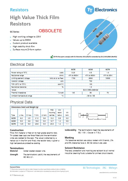
High Value Thick Film Resistors GC SeriesHigh working voltage to 10kV Values up to 900MCustom product available High stability thick filmSurface mount ZI-form optionResistors GC Series•High working voltage to 10kV •Value up to 1G ohm •Custom product available •High stability thick film GC55GC65GC70.15.052.0s t t a w C °07 t a g n i t a r r e w o P 33M o t K 74 0M 09 o t K 74 0M 09 o t K 74s m h o e g n ar e c n a t s i s e 0000100530071k a e P c a r o c d s t l o V e g a t l o v t n e m e l e g n i t i m i L 007s t l o v e g a t l o v n o i t a l o s I 001C°/m p p )C °07 o t C °02( R C T 5,1%e c n a r e l o t e c n a t s i s e R ValuesE24 & E96 preferred709041tt a w /C °ec n ade p m i l a m r e h T 551 o t 55 -C °e g n a r e r u t a r e p m e t t n e i b m A General Note Welwyn Components reserves the right to make changes in product specification without notice or liability. All information is subject to Welwyn’s own data and is considered accurate at time of going to print.© Welwyn Components Limited · Bedlington, Northumberland NE22 7AA, UKTelephone: +44 (0)1670 822181 · Facsimile: +44 (0)Electrical DataA subsidiary of TT electronics plc Welwyn ComponentsConstructionThick film material is fired on to high grade ceramic rods.Tin plated steel caps are force fitted and the termination wires are welded to the caps. The value is obtained by a helical cut in the film and finally the resistor body is given a high temperature protective coating.TerminationsMaterial Solder coated copper wire.StrengthThe terminations satisfy the requirements of IEC 68.2.21.SolderabilityThe terminations meet the requirements of IEC 115-1, Clause 4.17.3.2.Marking1% tolerance resistors are colour coded with 5 bands, 2%and 5% tolerance have 4, IEC 62 colours are used.Solvent ResistanceThe body protection and marking are resistant to all normal industrial cleaning fluids suitable for printed circuit boards.Dimensions (mm) and Weight (g)PCBMinmounting bendWtTypeL max.D max. f min. d nom.centres radius nom.GC556.22.521.00.610.20.60.3GC659.0 3.619.60.813.7 1.20.6GC7014.5 5.323.60.820.3 1.2 1.1Physical DataL DfdHigh Value Thick Film Resistors GC Series•High working voltage to 10kV •Value up to 1G ohm •Custom product available •High stability thick film GC55GC65GC700.15.052.0s t t a w C °07 t a g n i t a r r e w o P 33M o t K 74 0M 09 o t K74 0M 09 o t K 74s m h o e g n a r e c n a t s i s R 0000100530071k a e P c a r o c d s t l o V e g a t l o v t n e m e l e g n i t i m 007s t l o v eg a t l o v n o i t a l o s I 001C°/m p p )C °07 o t C °02( R C T 5 ,1%e c n a r e l o t e c n a t s i s e R ValuesE24 & E96 preferred709041tt a w /C °e c n a d e p m i l a m r e h T 551 o t 55 -C °eg n a r e r u t a r e p m e t t n e i b m A Electrical Data Welwyn ComponentsDimensions (mm) and Weight (g)PCB Min mounting bend WtType L max. D max. f min. d nom.centres radius nom.GC55 6.2 2.521.00.610.20.60.3GC659.0 3.619.60.813.71.20.6GC7014.5 5.323.60.820.31.2 1.1Physical Data L DfdResistorsGeneral NoteTT Electronics reserves the right to make changes in product specification without notice or liability.All information is subject to TT Electronics’ own data and is considered accurate at time of going to print.© TT Electronics plc/resistorsBI Technologies IRC WelwynAll Pb-free parts comply with EU Directive 2011/65/EU amended by (EU) 2015/863 (RoHS3)OBSOLETEHigh Value Thick Film ResistorsGC Series© TT Electronics plc/resistors OBSOLETE。

November 2011© 2011 Fluke Corporation. All rights reserved. Specifications are subject to change without notice. All product names are trademarks of their respective companies.700G SeriesPressure GaugeUsers ManualLIMITED WARRANTY AND LIMITATION OF LIABILITYThis Fluke product will be free from defects in material and workmanship for three years from the date of purchase. This warranty does not cover fuses, disposable batteries, or damage from accident, neglect, misuse, alteration, contamination, or abnormal conditions of operation or handling. Resellers are not authorized to extend any other warranty on Fluke’s behalf. To obtain service during the warranty period, contact your nearest Fluke authorized service center to obtain return authorization information, then send the product to that Service Center with a description of the problem.THIS WARRANTY IS YOUR ONLY REMEDY. NO OTHER WARRANTIES, SUCH AS FITNESS FOR A PARTICULAR PURPOSE, ARE EXPRESSED OR IMPLIED. FLUKE IS NOT LIABLE FOR ANY SPECIAL, INDIRECT, INCIDENTAL OR CONSEQUENTIAL DAMAGES OR LOSSES, ARISING FROM ANY CAUSE OR THEORY. Since some states or countries do not allow the exclusion or limitation of an implied warranty or of incidental or consequential damages, this limitation of liability may not apply to you.Fluke CorporationP.O. Box 9090 Everett, WA 98206-9090 U.S.A. Fluke Europe B.V. P.O. Box 1186 5602 BD Eindhoven The Netherlands11/99Table of ContentsTitle Page Introduction (1)How to Contact Fluke (1)Standard Equipment (2)Safety Information (2)Hazard Location Information/Approvals (3)Special Conditions for Safe Use (3)Symbols (4)Display and Buttons (5)Operation (6)How to Setup the Product (6)Engineering Units (6)Set Auto Off (7)Show Battery Voltage (7)Display Actual Temperature (7)i700G SeriesUsers ManualSet Damping (7)Set Sample Rate (7)Set TARE (7)Function Lock (8)Supervisory Mode (8)Available Pressure Ranges (8)How to Set a Custom Engineering Unit or Scale (9)Battery Life (9)Maintenance (9)How to Clean the Product (9)How to Change the Batteries (10)Accessories (11)RS-232 Interface (11)Specifications (12)Available Input Ranges (12)Accuracy (12)Media Compatibility (12)Environmental (12)Mechanical Specifications (13)PI Ranges and Resolution (14)iiList of TablesTable Title Page (4)1. Symbolsand Buttons (5)2. Displayiii700G SeriesUsers ManualivList of FiguresTitle Page FigureProduct (5)1. TheBatteries (10)the2. Changev700G SeriesUsers ManualviIntroductionThe 700G Series Pressure Gauges (the Product) are high-accuracy digital pressure test gauges. Accurate to 0.05 % FS, the Products can be used as a calibration reference, or in any application where high-accuracy pressure measurement is required.The Product features user-configurable functions that include:• Samplingrate• Tare• Damping• Autooff•Min MaxWhen the Product is configured, you can lock its settings and use password protection to prevent configuration changes. How to Contact FlukeTo contact Fluke, call one of the following telephone numbers:•Technical Support USA: 1-800-44-FLUKE(1-800-443-5853)•Calibration/Repair USA: 1-888-99-FLUKE(1-888-993-5853)•Canada: 1-800-36-FLUKE (1-800-363-5853) •Europe: +31 402-675-200• Japan:+81-3-6714-3114• Singapore:+65-738-5655•Anywhere in the world: +1-425-446-5500Or, visit Fluke’s website at .To register your product, visit .To view, print, or download the latest manual supplement, visit /usen/support/manuals.1700G Series Users Manual2Standard EquipmentThe Product ships with: • Protective Cover •Three AA Batteries (installed)• NPT/metric AdapterSafety InformationA Warning identifies conditions and procedures that are dangerous to the user. A Caution identifies conditions and procedures that can cause damage to the Product or the equipment under test.XW WarningTo prevent possible electrical shock, fire, or personal injury: •Use the Product only as specified, or the protection supplied by the Product can be compromised.• The battery door must be closed and locked before you operate the Product. •Replace the batteries when the low battery indicator ( )shows to prevent incorrect measurements.•Do not use and disable the Product if it is damaged.• Read all safety Information before youuse the Product.•Do not use the Product in damp or wet environments.W CautionTo avoid possible damage to Product or to equipment under test: •If the display reads “OL” the range limit is exceeded and the pressure source must immediately be removed. •Do not exceed the maximum torque allowed. Maximum torque allowed is 13,5 Nm = 10 ftlbs.Safety InformationHazard Location Information/ApprovalsEx Hazardous AreasAn Ex-hazardous area as used in this manual refers to an area made hazardous by the potential presence of flammable or explosive vapors. These areas are also referred to as hazardous locations, see NFPA 70 Article 500.) ® LR110460Class I, Div. 2, Groups A-D(II 3 G Ex nA IIB T6KEMA06ATEX0014XTa=–10°C...+55°C Special Conditions for Safe UseMisuseIf the Product is exposed to overpressure or sudden physical shock (such as being dropped) examine it for any damage that can cause a safety concern. If necessary, return the Product for evaluation to Fluke. Refer to the How to Contact Fluke section.W WarningTo prevent possible fire, or personal injury:•Do not use the Product with flammable substances.•The Product is intended for installation only in locations providing adequateprotection against the entry of solidforeign objects or water capable ofimpairing safety.Users ManualSymbolsSymbols used on the Product and in this manual areexplained in Table 1.Table 1. SymbolsSymbol Meaning SymbolMeaning W Risk of danger. Important information. See manual. P Conforms to European Union directives.X Hazardous voltage. Risk of electrical shock. )Conforms to relevant North AmericanSafety Standards.f Pressure ~Do not dispose of this product as unsorted municipal waste. Go to Fluke’s website for recycling information.Conforms to relevant Australian standards. (Conforms to ATEX requirementsDisplay and ButtonsDisplay and ButtonsThe Display and Buttons are shown in Figure 1. The Buttons are explained in Table 2.gsn001.epsFigure 1. The ProductTable 2. Display and ButtonsItem FunctionPush to turn the Product on. Push again toturn it off.Zeros the display. In Configure Mode, pushthe button to move forward through themenus.MIN MAX records minimum and maximumpressure values and saves them inmemory. Push to show maximum(MAX) indication. Push again to showminimum (MIN) indication. After 2 seconds,the gauge goes back to live operation.To clear the MIN MAX memory values,push and hold for 2 seconds until CLris shown.In Configure Mode, push ( ) to movebackward through the menus.Users ManualTable 2. Display and Buttons (Cont)Item FunctionPush to go to setup and configurationmenus.Push to make a selection. When the Product is not in Configuration mode, push to turn on the backlight. Push again to turn off the backlight.NPT Connector Pressure Display Engineering Units Bargraph OperationThe subsequent sections tell you how to operate the Product. Push to turn on the Product.The analog bar graph at the bottom of the display shows the applied-pressure level relative to the full range of the gauge.NoteIf you record a Tare value, the pressure shownis not the actual pressure applied.How to Setup the ProductBefore you use the product, it is necessary to configure it for your application. Push to go to the Setup menu. Each time is pushed, the display goes to the subsequent function. Push or to change the parameter value. When a parameter is set, push to exit the configuration menu or to move to the next parameter.Engineering UnitsThe Product’s default engineering unit shows psi. To change this, push and to move through the 23 standard engineering units plus one custom unit/scale. When the necessary unit shows, push or . Pressure now shows in the chosen engineering units. See the Specifications section for a list of available engineering units. See the Supervisory Mode section for instructions to set up custom units.OperationSet Auto OffAuto Off can be set in 1-minute increments from 1 to 30 minutes or you can turn off the function for continuous Product operation. The Product is configured for 30 minutes. Push and to set the necessary interval. The “off” position is at the low end of the selections, less than 1 minute.Show Battery VoltageActual battery voltage and a percent-of-life bargraph show the battery charge. No adjustments are made in this parameter.Display Actual TemperatureThe Product is temperature compensated This parameter shows the temperature measured by the internal sensor. Push or to show degrees F or C.Set DampingSelections are “on” and “off” . Damping smooths readings from pulsating pressure sources. Set Sample RateThis function finds how often pressure is sampled and the display is updated. Selections are 0.5, 1, 3, and 10 samples/second. Note that 10/second gives the fastest response time.Set TareUse this function to set a constant offset value which is then subtracted from the measured pressure. For example, if a tare is set at 30 psi, and the measured pressure is 37 psi, 7 psi is shown.A pressure of 27 psi is shown as -3 psi.Push and to set the tare value. The value, is based on the engineering units and resolution selected for display. Tare value can be set to the maximum range of the gauge.For safety, the bar graph always shows the actual pressure based on the full range of the gauge regardless of the tare position. This is done to make sure that even with a “0” reading pressure is being applied to the gauge.Users ManualFunction LockWhen set, access to each of the settable parameters above can be turned “off” to prevent unauthorized configuration changes. This is done with password protection in Supervisory mode. Push to access Supervisory mode or to go back to normal operation. Supervisory ModeIf necessary, each user-configurable parameter can be edited when you receive the Product. Some parameters are locked and must be unlocked to configure them. Use Supervisory mode to do this.When you are in the Configure menu, and FUnC LOCK is shown, it means that there are locked parameters.To disable function lock:1. Push . 0 PWRD is then shown.2. The password “101” is required to unlockSupervisory mode. Push to put in the passwordentry. Hold or down to move faster through the selections by a factor of 10. When you stop thecounter, push and again to move forward orbackward by a factor of 1. The password is factoryset and cannot be changed.3. Push .From this point each parameter can be locked or unlocked. Push and to select UnLOC or LOC for each parameter. To move to the next parameter, push .You can access, lock, or unlock these functions: •Zero function (enable/disable)•Set pressure units (enable/disable)•Auto shutdown adjustment (enable/disable) •Damping settings (enable/disable)•Sample rate setting (enable/disable)•Tare setting (enable/disable)•Custom engineering units (set scale factor)When a function is locked, it cannot be accessed or changed from its current condition until you go to Supervisory Mode and unlock it.Available Pressure RangesAvailable pressure ranges are listed in the Specifications section.Battery LifeHow to Set a Custom Engineering Unit or Scale The last menu selection in Supervisory mode isSET FACTR. You can set a multiplier factor from 0.001 to 100 to make a custom scale. The set factor is multiplied by the psi measured and the result is shown. Example: 40 psi is the equivalent of 1000 lbs of product in a tank. You want to show the product weight with a 100 psi gauge. If you set a factor of 25, 40 psi pressure would show as 1000 (40 x 25). The engineering unit shown is Cust (custom).Battery LifeBattery life is approximately 1500 hours (60 days) of continuous operation with the backlight off. With intermittent operation, batteries could last a year or more. When the battery voltage is low, the low-battery icon ( ) shows on the top left of the display. To replace the batteries, see the How to Change the Batteries section. MaintenanceHow to Clean the ProductClean the Product with a soft cloth dampened with water or water and weak soap.W CautionTo prevent possible damage to the Product,do not use solvents or abrasive cleansers.W CautionFor safe operation and maintenance of theproduct:•Repair the Product before use if thebattery leaks.•Remove batteries to prevent batteryleakage and damage to the Product if itis not used for an extended period.•Be sure that the battery polarity iscorrect to prevent battery leakage.•Have an approved technician repair the Product.Users ManualHow to Change the BatteriesXW WarningTo prevent possible electrical shock, fire, orpersonal injury, batteries must only bechanged in an area known to be non-hazardous. Explosion hazard.To change the batteries, see Figure 2:1. Use a Phillips screwdriver to loosen the captivescrew on the battery door.2. Remove the battery door.3. Replace the three AA batteries.4. Install the battery door again.5. Tighten the captive screw.gsn002.epsFigure 2. Change the BatteriesAccessories AccessoriesRS-232 InterfaceThe Product includes an RS-232 interface. Remove theProduct holster and the input jack is on the back of theProduct. You can use serial communication to configureand calibrate the Product and move measurement datafrom the Product to a PC. An RS-232/USB cable is soldseparately and includes 700G/TRACK Software. Forspecifications on the interface, see the Specificationssection.XW WarningTo prevent possible electrical shock, fire, orpersonal injury, do not use the RS-232interface in hazardous areas.Users ManualSpecificationsAvailable Input RangesSee PI Ranges and Resolution for available ranges in psi plus equivalent ranges and resolution for all engineering units. AccuracyPositive Pressure ............................................................................ ±0.05 % FSVacuum .......................................................................................... ±0.1 % FSTemperature Compensation ........................................................... 15 °C to 35 °C (59 °F to 95 °F) to rated accuracyNote: For temperatures from -10 °C to 15 °C and 35 °C to 55 °C, add .003 % FS/°CMedia Compatibility15, 30 psi ........................................................................................ any clean dry non-corrosive gas100, 300, 1000 psi .......................................................................... any liquids or gases compatible with 316 stainless steel Above 1000 psi ............................................................................... any non-flammable, non-toxic, non-explosive, non-oxidizing liquid or gas compatible with 316 stainless steel. EnvironmentalOperating Temperature .................................................................. -10 °C to +55 °C (14 °F to 131 °F)Storage .......................................................................................... -20 °C to +70 °C (-4 °F to +158 °F)Humidity ......................................................................................... 10 % to 95 % RH Non-condensingPollution Degree (2)Agency Approvals ........................................................................... P, , )(Mechanical SpecificationsDimensions .................................................................................... 11.4 x 12.7 (cm), depth = 3.7 cm(4.5 x 5 (in), depth= 1.5 in)PressureConnection ............................................................................. ¼in NPT MaleHousing .................................................................................. C ast ZNALDisplay5-1/2 Digits, 16.53 mm (0.65 in) high20-Segment bar graph, 0 to 100 %PowerBattery ................................................................................... t hree size AA alkaline batteriesBattery Life ............................................................................ 1,500 hours without backlight (continuous on),2,000 hours at slow sample ratePI Ranges and ResolutionNumber 700G04 700G05 700G06 700G27 700G07 700G08 700G29 700G30 700G31 Model100003000 5000 Range 15 30 100 300 500 1000PressureRange -14 -14 -12 -12 -12 -14 -14 -14 -14 Vacuum10000 1000015000 Pressure 500 500 1000 2000 2000 10000Burst150006000 10000ProofPressure 60 60 200 600 1000 2000EngineeringFactorUnitpsi 1 15.000 30.000 100.00 300.00 500.00 1000.0 3000.0 5000.0 10000bar 0.06894757 1.0342 2.0684 6.8948 20.684 34.474 68.948 206.84 344.74 689.48 mbar 68.94757 1034.2 2068.4 6894.8 20684 34474 68948 * * *kPa 6.894757 103.42 206.84 689.48 2068.4 3447.4 6894.8 20684 34474 68948 Mpa 0.006894757 0.1034 0.2068 0.6895 2.0684 3.4474 6.8948 20.684 34.474 68.948kg/cm2 0.07030697 1.0546 2.1092 7.0307 21.092 35.153 70.307 210.92 351.53 703.07 @0°C 51.71507 775.73 1551.5 5171.5 15515 25858 51715 * * * mmHg0°C 2.03603 30.540 61.081 203.60 610.81 1018.0 2036.0 6108.1 10180 20360 @inHg4°C 70.3089 1054.6 2109.3 7030.9 21093 35154 70309 * * * @cmH2O@20°C 70.4336 1056.5 2113.0 7043.4 21130 35217 70434 * * *cmH2O4°C 703.089 10546 21093 70309 * * * * * * @mmH2O20°C 704.336 10565 21130 70434 * * * * * * mmH2O@@4°C 0.703089 10.546 21.093 70.309 210.93 351.54 703.09 2109.3 3515.4 7030.9 mH2O20°C 0.704336 10.565 21.130 70.434 211.30 352.17 704.34 2113.0 3521.7 7043.4 @mH2O4°C 27.68067 415.21 830.42 2768.1 8304.2 13840 27681 83042 * *inH2O@@20°C 27.72977 415.95 831.89 2773.0 8318.9 13865 27730 83189 * *inH2O60°F 27.70759 415.61 831.23 2770.8 8312.3 13854 27708 83123 * *inH2O@ftH2O4°C 2.306726 34.601 69.202 230.67 692.02 1153.4 2306.7 6920.2 11534 23067 @20°C 2.310814 34.662 69.324 231.08 693.24 1155.4 2310.8 6932.4 11554 23108 ftH2O@60°F 2.308966 34.634 69.269 230.90 692.69 1154.5 2309.0 6926.9 11545 23090 @ftH2OSeaWater 2.24719101 33.708 67.416 224.72 674.16 1123.6 2247.2 6741.6 11236 22472 ftWater 0.68494382 10.274 20.548 68.494 205.48 342.47 684.94 2054.8 3424.7 6849.4 SeamTorr 51.71507 775.73 1551.5 5171.5 15515 25858 51715 * * *。

700G SeriesPressure Gauges用户手册November 2011, Rev. 2, 8/17 (Simplified Chinese)© 2011-2017 Fluke Corporation. All rights reserved. Specifications are subject to change without notice.All product names are trademarks of their respective companies.在正常使用和维护条件下,Fluke公司保证每一个产品都没有材料缺陷和制造工艺问题。
保证期为从产品发货之日起二(2)年。
部件、产品修理和服务的保证期限为90天。
本项保证仅向授权零售商的原始买方或最终用户提供,并且不适用于保险丝和一次性电池或者任何被Fluke公司认定由于误用、改变、疏忽、意外非正常操作和使用所造成的产品损坏。
Fluke公司保证软件能够在完全符合性能指标的条件下至少操作90天,而且软件是正确地记录在无缺陷的媒体上。
Fluke公司并不保证软件没有错误或无操作中断。
Fluke公司仅授权零售商为最终客户提供新产品或未使用过产品的保证。
但并未授权他们代表Fluke公司提供范围更广或内容不同的保证。
只有通过Fluke授权的销售商购买的产品,或者买方已经按适当的国际价格付款的产品,才能享受Fluke的保证支持。
在一个国家购买的产品被送往另一个国家维修时,Fluke公司保留向买方收取修理/更换零部件的进口费用的权利。
Fluke公司的保证责任是有限的,Fluke公司可以选择是否将依购买价退款、免费维修或更换在保证期内退回到Fluke公司委托服务中心的有缺陷产品。
要求保修服务时,请与就近的Fluke授权服务中心联系,获得退还授权信息;然后将产品连同问题描述寄至该服务中心,并预付邮资和保险费用(目的地离岸价格)。

HD160CHeavy-Duty Digital MultimeterRugged autoranging meter with true-rmsKey features:■Measures 1500 VDC■CAT IV 1000 V■IP67 Rated■Temperature, Frequency& Capacitance■Magne-Grip™ holsterwith magnetic hangingstrap■Highest voltage capability,measuring to 1500 Vdc and 1000Vac■CAT IV 1000 V rated■Special sealing for environmentand water resistance. IP67 rated■Constructed with drop-resistanthousing and PCB mounting■Measures capacitance,temperature and frequency■Superior 10,000 count resolutionwith bar graph■Magne-Grip™ holster, frees bothGeneral SpecificationsDisplay 4 digit LCD, 9999 counts, with annunciators, menu features and 41 segment bargraph.Polarity Indication AutomaticOper. Temp. 0 °C to +50 °C @ 0 to 75 % R.H.Storage Temp. -20 °C to 60 °C @ 0 to 80 % RH, battery removedAltitude 2000 meters - indoor useTemperature coefficient 0.1 x (spec. accuracy)/°C (0 °C to 18 °C and 28 °C to 50 °C)Fuse F 2 A/1500 V fuse (8 mm x 65 mm), I.R. 30 kA – Amprobe p/n FP700Power Standard 9-volt battery, NEDA 1604, JIS 006P, IEC 6F22Auto Power-Down Meter powers down after approximately 30 minutes of inactivity. Not in Min/Max function.Battery Life (typical) 150 hours, alkaline. Backlight usage consumes extra power and will decrease battery life significantly.Backlight auto-off after approx. 60 seconds.Dimensions, without holster(H x W x D) 200 x 102 x 59 mm (7.9 in x 4.0 in x 2.3 in)Weight (incl. battery) 642 g (22 oz)Accessories Heavy Duty CAT IV 1000 V Test leads with threaded alligator clips (TL1500), battery (installed), hexwrench (inside holster), Holster with Magne-Grip strap, Type K thermocouple probe (TP255), Tempera-ture Adaptor (TA-1A) and User Manual.Case material Reinforced, high-impact, fire retardant thermoplasticSafety Meets EN 61010-1 CAT IV 1000 V (1500 V DC max) Class II, EN 60529:IP67EMC Meets EN 61326-1Electrical Specifications (Accuracy at 23 °C ± 5 °C, <75 % RH, guaranteed for one year.)Function Range AccuracyDC VoltsRanges 1000 mV, 10 V, 100 V, 1500 VResolution 0.1 mV in 1000 mV rangeAccuracy ±(0.1 % rdg + 5 dgt)Input Impedance 10 MΩCMRR >120 dB up to 1500 V dcNMRR >60 dB at 50 or 60 HzOL Protection 1500 V dc or 1000 V ac rms.Transient protection 12 kV impulse (1.2 µS/50 µS) based on EN 61010-1:2001 impulse requirement for at CAT IV 1000V/1500V dc product. This product should not be used in installations where transients exceed 12 kV. AC Volts True rmsRanges 1000 mV, 10 V, 100 V, 1000 VResolution 0.1 mV in 1000 mV rangeAccuracy 1000 mV (45 Hz to 400 Hz) ± (1.2 % rdg + 10 dgt)10 V, 100 V (45 Hz to 500 Hz) ± (1.2 % rdg + 10 dgt)10 V, 100 V (500 Hz to 2 kHz) ± (2.0 % rdg + 10 dgt)1000 V (45 Hz to 1 kHz) ± (2.0 % rdg + 10 dgt) Input Impedance 10 MΩConversion type True rms, ac coupled 5 % to 100 % of rangeCrest factor ≤ 3OL Protection 1500 V dc or 1000 V ac rmsTransient protection 12 kV impulse (1.2 µS/50 µS) based on EN 61010-1:2001 impulse requirement for at CAT IV 1000 Vproduct. This product should not be used in installations where transients exceed 12 kV Amprobe® Test ToolsFunctionRangeAccuracyDC Current Ranges 100 µA, 1000 µA, 10mA, 100mA, 400mA, 2A (Auto/Manual ranging) Resolution 0.01µA in 100 µA range Accuracy 100 µA range ± (0.5% rdg + 10 dgts) 1000 µA to 400 mA ranges ± (0.5% rdg + 5 dgts) 2 A range ± (1.5% rdg + 10 dgts) Input protection 2 A/1500 V fast blow ceramic fuse 8×65 mm on A input , FP700 Burden voltage µA range of 1 mV/1 µA, mA range of 10 mV/1 mA, 2A range of 500 mV/1A, 500 mV max. (2 V max. on1000 µA, 100 mA, 400 mA, 2 A ranges)OL Protection A Input (F 2 A/1500 V, size 8 x 65 mm IR fast blow ceramic)AC Current True rms Ranges 100 µA, 1000 µA, 10 mA, 100 mA, 400 mA, 2 A Resolution 0.01 µA in 100 µA range Accuracy (45 Hz to 1kHz) 100 µA to 100 mA ± (1.5 % + 10 dgts) 400 mA ± (2.0 % + 10 dgts) 2 A ± (2.5 % + 20 dgts) Voltage burden see DC Current Conversion type True rms ac coupled 10 to 100% of range Crest factor ≤ 3 OL protection see DC Current Resistance Ranges 1000 Ω, 10 k Ω, 100 k Ω, 1000 k Ω, 10 M Ω, 40 M Ω Resolution 0.1 Ω in 1000 Ω range Accuracy 1000 Ω to 1000 k Ω ranges ± (0.5 % rdg + 8 dgts) 10 M Ω range ± (1.0 % rdg + 10 dgts) 40 M Ω range ± (2.0 % rdg + 10 dgts) Overload protection, all ranges 1500 V dc or 1000 V ac rms Continuity TestAudible indication Less than 40 Ω Response time 100 ms Overload protection 1500 V dc or 1000 V ac rms Capacitance Ranges 40 ηF, 400 ηF, 4 µF, 40 µF, 400 µF (3999 counts) (Auto/Manual ranging) Resolution 0.01 ηF Accuracy 40 ηF, 400 µF ranges ±(3.0% rdg +10 dgts) 400 ηF to 40 µF ranges ±(3.0% rdg +5 dgts) Test voltage < 1 V Test Frequency 1.3 Hz on 40 ηF to 40 µF ranges; 0.7 Hz on 400 µF range Overload protection 1500 V dc or 1000 V ac rms Temperature Ranges -20 °C ~ 1300 °C (-4° F ~ 2372 °F) 3999 counts Resolution 1 °C, 1 °F Accuracy -20 °C ~ 10 °C ±(2.0% rdg + 4 °C) 10 °C ~ 200 °C ±(1.0% rdg + 3 °C) 200 °C ~ 1300 °C ±(2.0% rdg + 2 °C) -4 °F ~ 50 °F ±(2.0% rdg + 8 °F) 50° F ~ 400 °F ±(1.0% rdg + 6 °F) 400 °F ~2372 °F ±(2.0% rdg + 4 °F) Overload protection 1500 V dc or 1000 V ac rms(continued on next page)Amprobe® Test Tools ©2012 Amprobe Test Tools. All rights reserved.11/2012 PN: 1646298 Rev BHD160C Technical Specifications (continued)FunctionRangeAccuracyFrequency Ranges 100Hz, 1000Hz, 10kHz, 100kHz, 1000kHz, 10MHz Resolution 0.01 Hz on 100 Hz range Accuracy ±(0.1% rdg + 5 dgts) S ensitivity 3 Hz to 1 MHz >2.5 V ac rms1MHz to 10MHz >2.5 V ac rms, <5 V ac rms Minimum input range 100 Hz range >3 Hz;1000 Hz range >30 Hz Minimum pulse width > 25 nsDuty cycle limits > 30 % and < 70 %Overload protection1500 V dc or 1000 V ac rmsIncluded AccessoriesHeavy Duty CAT IV 1000 V Test leads with threaded alligator clips (TL1500), battery (installed), hex wrench (inside holster), Holster with Magne-Grip strap, Type Kthermocouple probe (TP255), Temperature Adaptor (TA-1A) and User Manual.Optional AccessoriesTL1500 Cat IV 1000 V Test Leads with Alligator Clips CT235A 1000 A ac/dc ClampCT237A 200 A ac/dc Current Clamp CT238A 20 A ac/dc Current ClampVC221B Padded Vinyl Case. Fits meter & holster.DC205C Deluxe Hard-Shell Carry CaseDC207CLarge Deluxe Hard-Shell Carry Case with extra space for accessoriesHV231-10A High Voltage Probe FP700 Replacement Fuse, 2 A/1500 V, pack of two TA-1A K-type thermocouple, temperature adapterAmprobe® Test Toolswebsite: email:****************6920 Seaway Blvd. Everett, WA 98203 tel: 877-AMPROBEAmprobe® Test Tools Europe P.O. Box 11865602 BD Eindhoven The Netherlands。

Eaton Power-Sure 700 (10–500 kVA,three-phase voltage regulator)The Eaton Power-Sure ™ 700 reduces equipment downtime through constant voltage regulation. It is the ideal solution for equipment orfacilities experiencing brownouts and voltage regulation problems. The unique design of the Power-Sure 700 offers a high in-rush current, rapid response and operating advantages over other manufacturers.OverviewThe appropriate transformer tap is automatically activated through a silicon-controlled rectifier (SCR), maintaining a tightly regulated output voltage. Tap changes are initiated within one electrical cycle—switching at zero current crossing to ensure a minimum amount of noise during tap transitions. Seven taps per phase are used for optimal voltage regulation. Also, the Power-Sure 700 is a low output impedance, shielded isolation transformer. As a result of the lowimpedance, load changes do not affect other equipment connecting the system.The Power-Sure 700’s unique design ensures high efficiency at 97% and 1000% in-rush capability. It is equipped with a thermal-magnetic breaker that allows for proper system coordination to prevent nuisance trips.The Power-Sure 700 provides the triple function of isolation, noise attenuation and voltage regulation. The power transformer supplies the first two functions. The third function, voltage regulation, is supplied by the SCRs connected to taps on the power transformer. This sequential tap-changing design eliminates voltage “overshoot” from typical electronic voltage regulators, providing a seamless transition between the required power transformer taps.Power-Sure 700 features•±3% voltage output for a +10/–23% voltage input •Power factor—the Power-Sure 700 is notaffected by load power factor •Total harmonic distortion (THD)—the Power-Sure 700 adds less than 1% added to the output waveform under any dynamic linear loading conditions presented to the line regulator • High efficiency—97%•Wide input frequency range—the Power-Sure 700 operates within a broad input frequency range of 57–63 Hz•Integral manual rotarymaintenance bypass switch standard on 50–500 kVA units and optional on smaller units •Seven taps per phase used to provide optimal voltage regulation•Fail-safe bypass circuit, triple- shielded isolation transformer and overtemperature protection•One-year parts warranty with no startup required •Front-only access required (50–150 kVA units only) allows unit to be installed in tight spacesEaton is a registered trademark.All other trademarks are property of their respective owners.Eaton1000 Eaton Boulevard Cleveland, OH 44122United States © 2021 EatonAll Rights Reserved Printed in USAPublication No. PA158001EN / Z25666November 2021Power-Sure 700 ordering guidelinesA Units with no surge protection option, bypass option or metering option will have blanks in the last three spaces in the catalog number.B Bypass is standard on 50 kVA and larger units and an option on 45 kVA and smaller units.otes: NListings—UL ® Listed, CSA ® Certified, except for 600 V;no UL, CSA on 600 V units. For output distribution, call factory. K factor–rated units available on request.For product support, please contact Eaton’s Technical ResourceCenter (TRC) power quality application engineers at 1-800-809-2772, choose option 5 and then option 2, or *************.For more information, visit /pc .Follow us on social media to get the latest product and support information.。

e-mail:**************For latest product manuals:User’s GuideOL-700 SERIESShop online atMADE INIt is the policy of OMEGA Engineering, Inc. to comply with all worldwide safety and EMC/EMI regulations that apply. OMEGA is constantly pursuing certification of its products to the European New Approach Directives. OMEGA will add the CE mark to every appropriate device upon certification. The information contained in this document is believed to be correct, but OMEGA accepts no liability for any errors it contains, and reserves the right to alter specifications without notice.WARNING: These products are not designed for use in, and should not be used for, human applications.WARRANTY/DISCLAIMEROMEGA ENGINEERING, INC. warrants this unit to be free of defects in materials and workmanship for a period of 13 months from date of purchase. OMEGA’s WARRANT Y adds an additional one (1) month grace period to the normal one (1) year product warranty to cover handling and shipping time. T his ensures that OMEGA’s customers receive maximum coverage on each product.If the unit malfunctions, it must be returned to the factory for evaluation. OMEGA’s Customer Service Department will issue an Authorized Return (AR) number immediately upon phone or written request. Upon examination by OMEGA, if the unit is found to be defective, it will be repaired or replaced at no charge. OMEGA’s WARRANTY does not apply to defects resulting from any action of the purchaser, including but not limited to mishandling, improper interfacing, operation outside of design limits, improper repair, orunauthorized modification. This WARRANTY is VOID if the unit shows evidence of having been tampered with or shows evidence of having been damaged as a result of excessive corrosion; or current, heat, moisture or vibration; improper specification; misapplication; misuse or other operating conditions outside of OMEGA’s control. Components in which wear is not warranted, include but are not limited to contact points, fuses, and triacs.OMEGA is pleased to offer suggestions on the use of its various products. However, OMEGA neither assumes responsibility for any omissions or errors nor assumes liability for any damages that result from the use of its products in accordance with information provided by OMEGA, either verbal or written. OMEGA warrants only that the parts manufactured by the company will be as specified and free of defects. OMEGA MAKES NO OTHER WARRANTIES OR REPRESENTATIONS OF ANY KIND WHATSOEVER, EXPRESSED OR IMPLIED, EXCEPT THAT OF TITLE, AND ALL IMPLIED WARRANTIES INCLUDING ANY WARRANTY OF MERCHANTABILITY AND FITNESS FOR A PARTICULAR PURPOSE ARE HEREBY DISCLAIMED. LIMITATION OF LIABILITY: The remedies of purchaser set forth herein are exclusive, and the total liability of OMEGA with respect to this order, whether based on contract, warranty, negligence, indemnification, strict liability or otherwise, shall not exceed the purchase price of the component upon which liability is based. In no event shall OMEGA be liable for consequential, incidental or special damages.CONDITIONS: Equipment sold by OMEGA is not intended to be used, nor shall it be used: (1) as a “Basic Component” under 10 CFR 21 (NRC), used in or with any nuclear installation or activity; or (2) in medical applications or used on humans. Should any Product(s) be used in or with any nuclear installation or activity, medical application, used on humans, or misused in any way, OMEGA assumes no responsibility as set forth in our basic WARRANTY/DISCLAIMER language, and, additionally, purchaser will indemnify OMEGA and hold OMEGA harmless from any liability or damage whatsoever arising out of the use of the Product(s) in such a manner.RETURN REQUESTS/INQUIRIESDirect all warranty and repair requests/inquiries to the OMEGA Customer Service Department. BEFORE RET URNING ANY PRODUCT(S) T O OMEGA, PURCHASER MUST OBT AIN AN AUT HORIZED RET URN (AR) NUMBER FROM OMEGA’S CUST OMER SERVICE DEPART MENT (IN ORDER T O AVOID PROCESSING DELAYS). T he assigned AR number should then be marked on the outside of the return package and on any correspondence.The purchaser is responsible for shipping charges, freight, insurance and proper packaging to prevent breakage in transit.FOR WARRANTY RETURNS, please have the following informa-tion available BEFORE contacting OMEGA:1.Purchase Order number under which the product wasPURCHASED,2.Model and serial number of the product under warranty, and3.Repair instructions and/or specific problems relative to theproduct.FOR NON-WARRANTY REPAIRS,consult OMEGA for cur-rent repair charges. Have the following information avail-able BEFORE contacting OMEGA:1. Purchase Order number to cover the COST of the repair,2.Model and serial number of the product, and3.Repair instructions and/or specific problems relative tothe product.OMEGA’s policy is to make running changes, not model changes, whenever an improvement is possible. This affords our customers the latest in technology and engineering.OMEGA is a registered trademark of OMEGA ENGINEERING, INC.© Copyright 2009 OMEGA ENGINEERING, INC. All rights reserved. T his document may not be copied, photocopied, reproduced, translated, or。
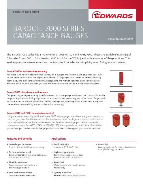
Features and benefitsApplicationsPRODUCT DATA SHEETBAROCEL 7000 SERIES CAPACITANCE GAUGESThe Barocel 7000 series has 3 main variants, 7025m, 7025 and 7045/7100. These are available in a range of full-scales from 1000 to 0.1 mbar/torr (100 to 10 for the 7025m) and with a number of flange options. This enables pressure measurement and control over 7 decades and simplicity when fitting to your system.• Superior performanceExcellent zero stability and accuracy • System enhancementSimple integration with dual set points for enhanced control • Flexible solutionsFrom compact to heated and everything between • Low cost of ownership Zero maintenance required• SemiconductorLoad lock, PVD, CVD, Etch • High energy physicsBeam lines, accelerators, laser evacuation, medical systems • AnalyticalMass spectrometry and electron microscopy • Quality & controlReference vacuum, batch control• IndustrialCoating systems, furnaces, sterilisation, food processing, oxidationBarocel 7025m - miniaturised accuracyFor those who need measurement accuracy on a budget, the 7025m is the gauge for you. Built on the same principles as the higher end Barocel 7000 gauges, this shares its ceramic sensing technology and excellent zero stability. Recognising the market need for a smaller more cost effective solution, this provides you with the first step on the way to a more efficient system.Barocel 7025 - benchmark performanceDesigned to give repeatable high performance, this is the gauge which sets the standard in a wide range of applications. Giving high levels of accuracy, it has been designed to be fit and forget, with multiple levels of internal protection; Baffle, coatings and shielding fitted as standard along with the excellent zero stability and any orientation mounting.Barocel 7045 and 7100 - temperature controlUsing the same measuring cell found in the 7025, these gauges then have integrated heaters to hold the gauges at fixed temperatures. For applications with harsh gasses, where condensation could cause an issue, we have implemented two levels of heated gauges. Heated to steady temperatures of either 45°C (7045) or 100°C (7100), these provide you with piece of mind that you will not get condensates in the gauge that could lead to damage to your control network.BOOST TECHNOLOGYTECHNICAL SPECIFICATIONS7025m702570457100FS options1000/100/101000/100/1010.11000/100/10/10.11000/100/10/10.1 Accuracy (% of reading)10.20.50.150.150.20.4 Temperature effectOn zero (percentage FS/°C) 0.020.0050.0150.020.00250.0050.00250.005 On span (% of reading/°C) 0.020.010.030.010.02Resolution (percent FS)0.050.0030.0030.003 Lowest reading (percent FS)0.050.050.050.05 Admissible tempsAmbient(°C) 0 to +70+5 to +50+10 to +40+10 to +50 Bakeout (at flange) (°C) <110<110<110<110 Storage (°C) -20 to +85-40 to +65-20 to +65-20 to +65 Burst pressure (bar)absolute6566 Supply voltage V (dc)+13 to +30+13 to +30+14 to +30 or +-15V+14 to +30 or +-15V Power consumptionDuring heat up (W) N/A N/A<12<15 At normal operation (W)<0.3<1<8<10 Output signal V (dc)+0 to +10+0 to +10+0 to +10+0 to +10 Response time (ms)100303030IP rating40304040 Dimensions NW16 (mm)28.3x28.3x9955x55x11382x82x14282x82x142 Set pointsNumbers of N/A222 Relay contact (V (dc))N/A303030Hysterisis (percent F.S)N/A111 Materials exposed tovacuum Aluminium oxide ceramic (AI2O3), stainless steel 1.4404 (AISI 316L)ORDERING INFORMATIONBarocel 7025m selection treeW611Pressure unit 1 = Torr 2 = mbarOutput0 = StandardFull scale (F.S)1 = 1000/11002 = 1003 = 10Flange 1 = NW162 = 8VCR 3 = DN16CFConnector 1 = RJ453 = D-Sub 9 pinBarocel 7025 selection treeW621Pressure unit 1 = Torr 2 = mbarFlange 1 = NW162 = 8VCR 3 = DN16CF Connector2 = D-Sub 15 pin 5 = D -Sub 15 pin & Dual RJ45*Full scale (F.S)1 = 1000/11002 = 1003 = 104 = 15 = 0.1*Only selectable with pressure units of torr and Output of “EtherCAT”. **Only available with D-Sub 15 pin.***Only available with D-SUB 15 pin & Dual RJ45Output0 = Standard**5 = EtherCAT***W63Barocel 7045/7100 selection treePressure unit 1 = Torr 2 = mbarHeatedTemperature (C)2 = 453 = 100Full scale (F.S)1 = 1000/11002 = 1003 = 104 = 15 = 0.1Flange 1 = NW162 = 8VCRConnector2 = D-Sub 15 pin 5 = D -Sub 15 pin & Dual RJ45**Only selectable with pressure units of torr and Output of “EtherCAT”. **Only available with D-Sub 15 pin.***Only available with D-SUB 15 pin & Dual RJ45Output0 = Standard**5 = EtherCAT***。
1、复合真空计使用说明1.1 主要性能:1.1.1 本复合真空计由一个热偶计和一个宽量程的复合真空计构成.热偶采用单一的一支ZJ—54D 热偶规管进行测量。
复合真空计用一支ZJ-54D 热偶规和一支ZJ-10 电离规进行测量。
1.1.2 测量范围:热偶计:103Pa~10-1Pa复合计:103Pa~10-4Pa 。
其中电离规3.5Pa~10-4Pa。
1.1.3 本复合真空计配有RS232 接口,可与带相应接口的计算机联机。
测量数据由计算机进行管理。
1.1.4 供电:本复合真空计采用单相220V 交流供电。
电压范围:220V AC±10%;消耗功率:≤30W1.1.5 使用和储存环境:温度:5℃~35℃湿度:0~85 %严禁在高温潮湿和有腐蚀性气体的环境下工作和储存。
严禁在工作时猛烈碰撞。
1.1.6 机箱尺寸:宽×高×深=480×119×320重量:约7Kg1.1.7 出厂时规管引线均为5m。
最长建议不要长于10m。
1.1.8 RS232 接口建议采用屏蔽电缆。
屏蔽线与机壳相连,并接地。
1.1.9 电离规的启动方式:由面板上的自动、手动开关控制。
自动方式下,热偶规测量值<3.5Pa时接通,>4.0Pa 时关闭。
手动方式下,由面板上的二个ON和OFF按纽控制。
当真空度大于10Pa时,请不要打开电离规。
2.操作说明:本复合真空计是采用单片机技术的智能化仪器。
打开电源后,真空计初始化显示“HZ HZ HZ HZ”初始化完后,热偶计直接进入工作状态。
没有接入规管或规管暴露在大气中时,都是显示103Pa。
复合计:分手动和自动启动方式,在面板上,设有电离规状态指示灯。
电离规关闭或没接或故障时,ZJ-10 指示灯亮。
在手动方式下,在没有接通电离规之前,若热偶规正常,则指示热偶规测量的真空值。
接通电离规后,显示的是电离规测量的真空度。
电离规测量值≥5.0Pa 时,自动关闭电离规灯丝。
B P G真空规管中文手册公司内部编号:(GOOD-TMMT-MMUT-UUPTY-UUYY-DTTI-IR 090热阴极电离复合真空计使用说明书BG 804 171 BE目录产品标识有效范围使用范围工作原理注册商标1 安全1.1 使用符号1.2 人员素质1.3 一般安全规则1.4 赔偿责任与保修2 技术参数3 安装3.1 真空连接3.1.1 拆卸和安装电子学单元3.1.2 安装延伸件3.2 电源连接3.2.1 与COMBIVAC IT23一起使用3.2.2 与其它测量仪器一起使用4 运行4.1 测量原理,测量特性4.2 真空计工作原理4.3 除气4.4 显示器4.5 RS232C接口4.5.1 功能说明IR090输出IR090输入5 维护5.1 维护5.2 真空计调整5.3 真空计清洗5.4 安装障板5.5 更换障板5.6 更换规管5.7 故障查找6 拆卸7 产品返修8 附件9 备件10 废物处理附录A. 测量讯号与压强的关系B. 气体种类与压强的关系污染申报表参阅本说明书中的章节,采用符号(→XY)。
参阅其它文献,采用符号(→[Z])。
产品标识与Leybold Inficon联系时,请标明产品标牌上给出的信息。
将信息复制在标牌的复印件上。
有效范围本说明书适用于下列件号的产品不带显示器120 90 (法兰DN 25 ISO-KF)120 92 (法兰DN 40 CF-R)带显示器120 91 (法兰DN 25 ISO-KF)120 94 (法兰DN 40 CF-R)产品的件号在标牌上标明。
本公司保留对说明书不预先通知的技术更改权。
使用范围IR090用于在压强5×10⁻¹⁰…1000毫巴范围内非易燃性气体和气体混合物的真空测量。
真空计规管是SKY Smart真空计规管系列的一个组成部分。
可与COMBIVAC IT23或其它测量仪器一起工作。
工作原理在整个测量范围内,热阴极电离复合真空计有连续的测量特性。
微机型数显复合真空计使⽤说明书⽬录1、安全说明 (1)2、技术参数 (2)3、⼯作原理 (3)4、性能概述 (4)5、使⽤概述 (5)6、规管性能概述 (7)7、规管外形及安装 (10)8、真空计与规管连线 (12)9、真空计开机及显⽰说明 (13)10、真空计使⽤⽅法 (13)10.1电阻2单元使⽤⽅法 (13)10.2电阻1与电离复合单元使⽤⽅法 (15)11、真空计去⽓ (17)*12、控制功能及设定⽅法 (17)*13、控制输出 (18)*14、扩展功能 (20)机箱规格 (22)15、附录规管接⼝ (24)常见问题 (27)*号内容属选配功能说明,仅选配了此功能相应配置有效1、安全说明▲为确保该真空计的正常功能,使其具有较⾼的准确度、稳定性和较长的使⽤寿命,请根据本说明书中规定的允许值和应⽤条件进⾏操作和使⽤。
·操作、维护和维修该真空计时,请遵守电⽓设备的安全规范。
′·避免⼤⽓压下开启电离规灯丝,这将烧毁电离规灯丝。
·避免真空系统或管道有真空时,强制拆卸规管。
·避免⽤于“正压”的真空系统安装普通规管,应安装承受“正压”的规管。
·避免真空系统中腐蚀性⽓体腐蚀电阻规传感丝及电离规各电极,以延长规管寿命。
·采⽤适当措施防⽌误操作或不允许的损坏。
·如未按本说明书操作,我们将不承担任何责任;有关该真空计及其附件的保证条款也将⽆效。
该说明书使⽤符号说明:▲注意:表⽰必须遵循的信息,如未遵循可能会导致对⼈⾝的伤害和对该真空计的损坏。
●表⽰重要的附加信息和技巧或建议。
炫⾠钛⾦保留对产品外观及设计改进和改变的权利,⽽⽆需事先通知,产品及配件以实物为准。
2、技术参数2.1 电阻单元技术参数:·配⽤规管型号:ZJ-52T电阻规·电阻规传感丝冷态电阻值(86.5Ω±1.7Ω)·真空度测量范围(对⼲燥空⽓或氮⽓)1.0×10⁵~2.5×10³可测范围。