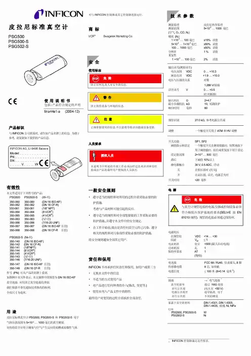
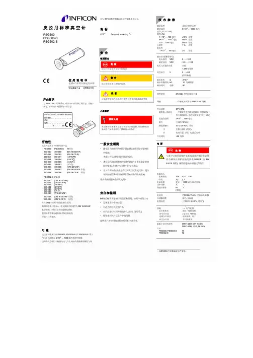
英福康(INFICON)皮拉尼标准真空计PSG500 操作手册
- 格式:pdf
- 大小:509.73 KB
- 文档页数:4

Maintenance ManualA Regal BrandIntroductionThe PM500 is an encapsulated electronic voltage regulator intended for use with the Marathon PMG systemand most Marathon AC generators. The PM500 controls the output of a brushless AC generator by regulating the DC current input to the exciter field. The PM500 is designed as a three phase or single phasetrue RMS sensing regulator that is capable of accepting analog voltage adjustment input. The PM500 is UL Recognized and UL Certified for Canada – Component per UL File E222903. The PM500 bears the CE markfor the European Union.SpecificationsSensing Input175 - 600Vac, True RMS, 60/50Hz, 3 Phase/1 PhasePower Input 175 - 260Vac, 300Hz PMG, 60/50Hz ShuntPower Output, Continuous 85Vdc at 3.5Adc with 240Vac input powerPower Output, Forcing 170Vdc at 7Adc for 10 sec. with 240Vac input powerFuse 5 x 20mm S505-5A, Slow Blow TypeVoltage Regulation ± 0.25%, with 4% engine governingExcitation Resistance9 ohms, minimumOver Excitation Protection Excitation exceeds 190Vdc or 7Adc for more than 10 seconds Manual Voltage Adjustment Range ± 20% with 2000 ohm rheostat± 10% with 1000 ohm rheostatAnalog Voltage Input A1 & A2 ± 20% with 0-10Vdc or ± 5Vdc biasUnder Frequency Factory Setting 58Hz preset for 60Hz operation and 48Hz preset for 50Hz operation Voltage Build-up Voltage build up from input voltage ≥ 5Vac at 25Hz.Response Time<1 CycleWeight16.6 oz.Operating Temperature -40°C to +60°CStorage T emperature -40°C to +85°CPower Dissipation12 watts, maximumSize 5.9” L x 5.3” W x 2.2” HThermal Drift 0.05% / °C change in AVR ambient temperature Electromagnetic Compatibility TestsImmunityIEC61000-4-2 - Electrostatic DischargeIEC61000-4-3 - Radiated RFIEC61000-4-4 - Electrical Fast TransientIEC61000-4-5 - SurgeIEC61000-4-6 - Conducted RFIEC61000-4-11EmissionEN61204-3 - Conducted RFCISPR 22IEC61000-3-2 - Harmonic IECIEC61000-3-3 - Flicker IEC2InstallationMOUNTINGThe PM500 is mounted through a keyed hole in the generator conduit box and secured with a plastic mounting nut.The PM500 should be mounted directly to the conduit box panel with the rubber gasket positioned between the outside of the conduit box panel and the mounting nut.Protect front panel adjustment pots by installing clear or black plastic cover.Mounting nut torque is 26 – 43 lbf-in. Refer to the Figure 1 for dimensions.Wiring and ConnectionsEXCITER FIELD POWER CIRCUITThe exciter field resistance must be ≥ 9 ohms.If the exciter field resistance is less than 9 ohms andthe full load field current does not exceed 3.5 amps, add a resistor in series of sufficient wattage to increase the total resistance to 9 ohms.Connect the generator F+ (F1) field lead to the regu- lator F+ terminal. Connect the generator F- (F2) field lead to the regulator F- terminal. Refer to Figure 3 for typical connection points.POWER I NPUT C IRCUITThe PM500 is designed to be powered by a PMG and capacitor. A 7.5µƒ capacitor is connected in parallel between the PMG leads and the regulator power input terminals.The regulator power input terminals are labeled P1 and P2. Connect leads from P1 and P2 to the capacitor terminals.Connect regulator terminals P1 & P2 to generator leads that will provide 240Vac output. No capacitor is used with the PM500 in shunt mode.Refer to Figure 3 for typical connection points.Figure 23TO PREVENT PERSONAL INJURY OR EQUIPMENT DAMAGE, ONLY QUALIFIED PERSONNEL SHOULD INSTALL, OPERATE OR SERVICE THIS DEVICE.Figure 1Wiring and Connections (cont’d)Figure 3a – Three PhaseFigure 3b – Single PhaseSENSING CIRCUITSSensing input range is 175 - 600Vac. DIP switch SW1 and SW2 must be set appropriately. Refer to Figures 3a & 3b for typical connections.Single Phase SensingConnect PM500 terminal E1 to output lead L1 and E2 to output lead L2. PM500 terminal E3 is jumpered to E2. 3 Phase SensingConnect PM500 terminal E1 to output lead L1, E2 to output lead L2 and E3 to output lead L3.If used in a paralleling application, a paralleling CT will be required in the generator B phase. Paralleling CT must be sized to provide either a 1A or 5A signal when the generator is under full load.4Wiring and Connections (cont’d)DIP SWITCH PROGRAMMINGEight DIP switches located on the back of the regulator must be set appropriately for correct regulator operation and generator control. Refer to Figure 4.Switches 1 & 2 set the regulator sensing range.Switches 3 – 8 Configure multiple functions: 3 or Single Phase Sensing, Frequency, Over Excitation Protection, kW Range and Paralleling CT Range.SW1 : OFF SW2 : OFF Volts ≤ 280VacSW1 : OFF SW2 : ON Volts ≤ 480VacSW1 : ON SW2 : ON Volts ≤ 600VacOFF ONSW3 : 3 Phase Sensing 1 Phase SensingSW4 :60 Hz 50 HzSW5 :O/E Protect On O/E Protect OffSW8 :CT 1A CT 5ASW6 : OFF SW7 : OFF< 90kWSW6 : ON SW7 : OFF90 - 500kWSW6 : ON SW7 : ON> 500kW PROTECTION F UNCTIONSThe PM500 has built in protection functions for Over Excitation, Under Frequency and Over Voltage Protection.Over ExcitationThe Over Excitation function protects the PM500 and generator components in the event the excitation system demands excessive levels of voltage and/or current to maintain output.The Over Excitation function will trip when excitation output exceeds 190Vdc or 7Adc for more than 10 sec. with 220Vac input power.The Over Excitation O/E LED on the front panel will be illuminated when thePM500 when the OverExcitation system has tripped. Replace the fuse on theback panel if required and inspect the generator. ThePM500 will reset when power is cycledUnder FrequencyUnder Frequency protection allows the generatorvoltage to decrease when the output frequency dropsbelow the Roll-Off point. This reduces the load on theengine, allowing engine RPM to recover. This is normaloperation and no reset is required.5 Figure 4Operating AdjustmentsSix adjustable potentiometers are accessible on the front panel of the PM500. These are: VOLT, STAB, U/F, DIP, DROOP and TRIM.Figure 6VOLTAGE ADJUST (VOLT)Set PointOutput voltage may be adjusted via the VOLT poten- tiometer on the front panel of the regulator. The set point range is 175 - 600Vac.Remote Voltage AdjustA 2000 ohm, 2 watt rheostat may be connected to VR1 and VR2 - replacing the factory jumper, providing a ±10% voltage adjustment range. T erminals A1 & A2 may not be used when a rheostat is installed.Analog Voltage AdjustRegulator terminals A1 & A2 may be connected to the analog output of a gen-set controller. The allowable voltage input range is 0-10Vdc or ± 5Vdc will provide a 20% range. Jumper VR1 & VR2 when analog voltage adjustment terminals are used.TRIM ADJUST (TRIM)The analog bias range is adjusted via the TRIM potenti-ometer on the front panel. Set the TRIM potentiometer fully clockwise to provide a ± 20% adjustment range. DROOP ADJUST (DROOP)Requires a 1A or 5A CT in the B Phase.DIP switch SW8 must be set appropriately.In a paralleling system, the PM500 adjusts the genera- tor output voltage when the B phase current leads or lags the B phase voltage.The adjustment range may be preset via the DROOP potentiometer. The default setting is full counter clock-wise for minimum range. Maximum range is ±7% at 1.7 PF lagging to 0.7 PF leading.UNDER FREQUENCY ROLL-OFF ADJUST (U/F) The Roll-Off point is the frequency at which the gen- erator output voltage is allowed to decrease and is factory preset at 57Hz for 60Hz operation and at 47Hz for 50Hz operation.When the U/F LED on the front panel it lit, the PM500 is operating in Under Frequency mode.To change the roll-off point, first verify that the gen-set is operating at the intended speed and voltage.Fixed Engine RPMOn most new engines (Tier 4i and up), the engine speed is fixed at 1800RPM or 1500RPM.Adjust the roll-off point by block loading the genera-tor and observing the U/F LED on the front panel. To ensure the generator maintains voltage under a given block load, adjust U/F potentiometer until the U/F LED remains off during the block load test.Adjustable Engine RPMAdjust engine speed to the new roll-off point. Verify that the output voltage still matches the intended set-point voltage.Next, adjust the U/F potentiometer clockwise until the voltage starts to drop off, then slightly adjust the poten- tiometer counterclockwise until the voltage returns to rated voltage. Re-adjust engine speed to rated speed. U/F DIP ADJUST (DIP)When Under Frequency (U/F) protection is activated, the voltage dip follows a linear Volts / Hertz curve. The voltage dip ratio may be adjusted via the DIP potentiometer with an adjustable range of 3-10V/Hz. The default setting is full clockwise for 10V/Hz. STABILITY ADJUST (STAB)Stability is the ability of the generator to respond to load changes. Decreasing the stability setting allows the generator to respond faster to load changes. If the stability setting is too low, the generator voltage will tend to hunt under steady state conditions.Correct stability adjustment must be conducted while the generator is operating unloaded.Adjust the STAB potentiometer clockwise until the voltage becomes unstable, then slightly adjust coun- terclockwise (Approximately 1/5 turn) until the voltage becomes stable.6Warnings & CautionsIMPORTANT INFORMATIONPlease Read CarefullyThis document is not intended to provide operational instructions. Appropriate Marathon Electric instructions provided with the generator and precautions attached to the generator should be read carefully prior to installation, operations and/or maintenance of the equipment. Injury to personnel or generator failure may be caused by improper installation, maintenance or operation.The following and information is supplied to you for your protection and to provide you with many•Buyer shall be solely responsible for determining the adequacy of the product for any and all uses to which Buyer shall apply the product. The application by Buyer shall not be subject to any implied warranty of fitness for a particular purpose.•For safety, Buyer or User should provide protective guards over all shaft extensions and any moving apparatus mounted thereon. The User is responsible for checking all applicable safety codes in his area and providingsuitable guards. Failure to do so may result in bodily injury and/or damage to equipment.•Hot oil can cause severe burns. Use extreme care when removing lubrication plugs.•Disconnect power and lock out drive equipment before working on a generator.•Always keep hands and clothing away from moving parts.•The lifting eyes on the generator are not to be used to lift the entire generator set. Only the generator may be safely lifted by the lifting eyes. Do not use the conduit box for lifting or support of the generator.•Install and ground the generator per local and national codes.•Discharge all capacitors before servicing the generator.•Misapplication of a generator in a hazardous environment can cause fire or an explosion and result in serious injury.•Never attempt to measure the temperature rise of a generator by touch. Temperature rise must be measured by thermometer, resistance, imbedded detector or thermocouple.•Operation of a generator at higher than its nameplate ratings may result in fire, damage to equipment or serious injury to personnel.•Do not apply any force to the generator fan when rotating the generator rotor.•Generators should not be operated faster than their rated speed.•The following statement is only applicable to high voltage generators (above 5000 V). A grounding strap is supplied from the generator neutral to ground. This grounding strap not only bleeds off any voltage potential on the main statorafter the high potential test, but also bleeds off any static charge that can build-up on the main stator during shipmentand storage. THIS GROUND STRAP IS NOT A PERMANENT PART OF THE GENERATOR CONSTRUCTION. REMOVETHIS GROUND STRAP ONLY AFTER A PERMANENT GROUND IS INSTALLED ON THE GENERATOR MAIN STATOR(not supplied by Marathon Electric), OR THE GENERATOR FINAL INSTALLATION IS COMPLETE.•Mounting bolts should be routinely checked to ensure that the unit is firmly anchored for proper operation.•Consult qualified personnel with questions. All electrical repairs must be performed by trained and qualified personnel only.•For inverter applications, follow the inverter manufacturer’s installation guidelines.•Make sure the generator is properly secured and aligned before operation.•When installing the generator, insure that loose parts or tools do not fall inside the generator.•When connecting the generator, be sure to follow the correct wiring diagram for the desired voltage. Insure that the voltage regulator is connected per the wiring diagram.RESALE OF GOODSIn the event of the resale of any of the goods, in whatever form, Resellers/Buyers will include the following language in a conspicuous place and in a conspicuous manner in a written agreement covering such sale:The manufacturer makes no warranty or representations, express or implied, by operation of law or otherwise, as to the merchantability or fitness for a particular purpose of the goods sold hereunder. Buyer acknowledges that it alone has deter- mined that the goods purchased hereunder will suitably meet the requirements of their intended use. In no event will the manufacturer be liable for consequential, incidental or other damages. Even if the repair or replacement remedy shall be deemed to have failed of its essential purpose under Section 2-719 of the Uniform Commercial Code, the manufacturer shall have no liability to Buyer for consequential damages.Resellers/Buyers agree to also include this entire document including the cautions and warnings above in a conspicuous place and in a conspicuous manner in writing to instruct users on the safe usage of the product.This information should be read together with all other printed information supplied by Marathon Electric.For more information contact: Regal Beloit America, Inc., 100 E. Randolph St., Wausau, WI 54401Phone: 715-675-3311 or Fax: 715-675-80267A Regal Brand100 E. Randolph Street PO Box 8003Wausau, WI 54402-8003 U.S.A. PH: 715-675-3359 FAX: 715-675-8026 ©2019 Regal Beloit Corp GPN056 v1.2100/11-19/FSPrinted in the U.S.A.。

CLINITEK®500中文操作手册注意:此中文操作手册根据拜耳公司2002年的英文操作手册翻译,拜耳公司保留对原英文资料的更新权。
您在使用该手册时,有疑问,请查阅英文手册,目录1. 介绍使用目的 5 仪器组成和操作 5 光学系统7 定标7 规格8 结果报告2. 安装一般信息9 环境因素9 打开步骤9 仪器设定10 与打印机连接15 与计算机连接16 与条形码读取装置连接16 仪器的初始化检验16 3. 如何选择一般信息18 设定常规19A.设定菜单 #1 (日期;时间;计算机连接口;打印机) 20B.密码显示屏22C.设定菜单 #2 (语言;结果单位;附加分类系统;测试) 22D.设定菜单 #3 (日期,时间形式;日期,时间的分隔) 23E.设定菜单 #4 (测试的报告;阳性水平;正常水平) 24F.设定菜单 #5 (颜色;选择颜色,透明度;使用省略值) 25G.设定菜单 #6 (阳性水平颜色,透明度;报告的标志) 26H.设定菜单 #7 (被编辑的报告标志;输入样本ID;实验者ID) 27I. 设定菜单 #8 (计算机连接选择;条形码读取装置:密码) 28J. 设定菜单 #9 (省略的设定;硬件测试) 304.仪器操作一般信息32 使用准备33 参照试样测试34 常规试样测试34 A.基本操作35 B.如果使用试样ID代码37 C.使用ID代码而没有试样目录38 测试结束报告39 编辑确认报告39 寻找结果39 操作注意事项40 5.仪器维护一般清洗41 日常清洗41 消毒43 换纸44 6.附件7.简单维修一般要求46 更换打印头46 校正可触式显示器48 8.故障排除和服务一般要求49 何时寻求帮助49 何处寻求帮助49 故障排除表50 服务记录表54 9.附件和维修备件56 附件维修备件56 附录CPL:计算机和打印机的连接口57 一般信息串行口线缆针并行口线缆针介绍使用目的泰利特500尿液化学分析仪是一种半自动化桌面测试仪,能够读取“Bayer”反应试剂条,进行尿液分析。
真空包装机操作、使用说明书真空包装机操作、使用说明书大江真空包装机械有限公司大江机械贸易有限公司说明书自述本说明书为整个系列真空包装机的使用说明书。
具体型号的使用说明请参照相关页面!具体机型:智能版型、普通型智能版型1 抽真空0~99S 充氮0~9.9S 加热0~9.9S冷却0~9.9S 电动开盖放气智能版型2 抽真空0~99S 充氮0~9.9S 加热0~9.9S冷却0~9.9S 放气智能版型3 抽真空0~99S 切丝0~9.9S 加热0~9.9S冷却0~9.9S 放气智能版型4 抽真空0~99S 加热0~9.9S 冷却0~9.9S放气普通型抽真空0~99S 加热0~9.9S 冷却0~9.9S放气各机型动作原理,内部结构,电器原理图,气路原理图,请根据机器功能参照相关页面!以上为现有通用机型,特殊机型及定制机型不在此列,具体情况请联系设备制造商!目录说明书自述-------------------------------------- 1目录-------------------------------------- 2用途及特点-------------------------------------- 3使用前准备-------------------------------------- 4操作说明-------------------------------------- 7气路原理图-------------------------------------- 9电气原理图-------------------------------------- 11故障分析-------------------------------------- 20用途及特点用途:本公司自发研制的全系列真空包装机具有功能优越,维护方便,操作简易,应用广泛等优点。
特别适用于复合薄膜或铝箔复合薄膜等软包装材料。
对固体、液体、粉状、糊状的食品,种子、芬芳物、药品、化工产品、电子产品、精密仪器仪表、稀有贵重金属等物品进行真空包装,或者真空后充入惰性气体包装。
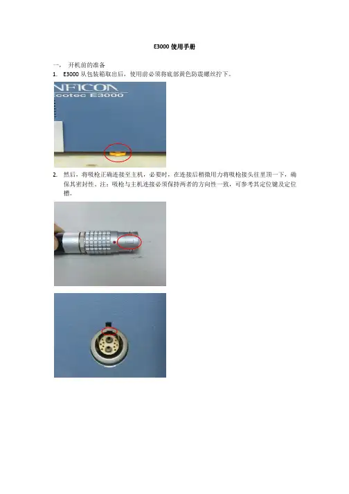
E3000使用手册一,开机前的准备1.E3000从包装箱取出后,使用前必须将底部黄色防震螺丝拧下。
2.然后,将吸枪正确连接至主机,必要时,在连接后稍微用力将吸枪接头往里顶一下,确保其密封性。
注:吸枪与主机连接必须保持两者的方向性一致,可参考其定位键及定位槽。
3.最后,将带接地连接头的电源线连接至主机,便可以开机。
注:必须保证电源系统有接地连接,同时,工作电压范围在200---250伏。
二,检漏仪启动过程1.检漏仪在开启后,便进入自动启动的过程中2.当启动参数均正常的情况下,且无任何故障报警,仪器便进入正常的检漏模式。
三,检漏仪使用检漏仪在首次使用或长时间存放后的第一次使用,我司建议仪器在预热三十分钟以后执行一次校准。
如果仪器处于一直在使用状态,可以先操作半小时后,再执行校准。
校准包括两种:外部校准及内部校准。
外部校准:凡是与主机分离开的标准漏孔,执行时,我们都称之为外部校准。
外部标准漏孔外部校准执行过程:1.将E3000检漏仪正常连接启动。
仪器预热三十分钟以上后,执行外部校准。
2.选择显示器右上角CAL键进入校准过程。
3.检漏仪提示“选择校准气体”,例如:执行R134a校准。
气体1为R134a,选择右上角“GAS1”4.在确定所执行校准的气体类型后,仪器提示“开始外部校准”。
5.根据外置式标准漏孔漏率设置检漏仪上的参数。
例如:现有一个4.18g/a的R134a漏孔。
6.进入界面中的“编制漏率”,通过左边上下键将漏率修正至4.2g/a(由于修正值以0.05为一个单元,因此尽可能将数值靠近外置式标准漏孔漏率)。
7.确认后,准备开始校准。
8.将吸枪对准标准漏孔后按“起始”。
9.E3000将提示“吸外部校准漏孔,如讯号稳定请按OK”。
10.确认信号波动不大时,按OK。
此时,仪器将对信号进行采样处理,因此,在期间必须保证吸枪不能离开标准漏孔。
11.当提示“吸入空气”时,将吸枪移开标准漏孔,尽量使吸枪吸入新鲜空气。
UV500检测器操作说明500检测器的使用和维护图2.1:检测器前面板16789111112534前面板见图2.1:以下控制和指示器位于前面板上:1)显示屏:A31/2数字显示器。
吸收值可显示到1.999AU。
当按下开关8(SAMP)时,这个显示屏显示样品相对光密度,当按下开关9(REF)时,这个显示屏显示参照光强度。
2)上升时间选择开关:一个四档旋转开关控制,能控制二级Beel滤器的过滤强度。
可选择的上升时间有0.1,0.3,1.0和3.0秒四档。
上升时间等于2倍的时间常数。
(以秒为单位)3)灵敏度选择开关:十二档的旋转开关控制仪器背板上的输出口的输出电压范围。
可供选择的有 2.0,1.0,0.5,0.2,0.1,0.05,0.02,0.01,0.005,0.002,0.001,和0.0005AUFS。
这个开关不控制仪器背板上的1V/AU积分仪输出端口的输出。
4)波长选择器:连续波长旋钮,可调范围190-800nm。
顺时针旋转降低波长,逆时针旋转增加波长。
箭头指示波长增加方向。
注意:不要强力旋转旋钮,使波长值低于180nm或高于820nm这会损坏波长控制器。
5)波长指示器:一个三位的机械波长指示器,显示当前工作波长。
6)紫外(UV)灯指示器:绿色发光二极管亮表示氘(D2)灯装于设备内并且发光。
7)可见光(VIS)灯指示器:绿色二极管灯亮表明这个设备内装着一个钨灯并且发光。
8)样品光强度开关:按下这个瞬间开关,显示器显示样品室光敏二极管测到的样品光密度。
9)参照光密度开关:也是瞬间开关,按下此开关,显示器显示参照光敏二极管测到的参照光密度。
10)短路开关:瞬时开关,按下这个按钮,记录仪输出端电压降为零伏。
这个按钮必须持续按压一会才能发挥作用。
这个按钮用于调整记录笔在记录纸上的位置,但不影响积分仪输出。
11)标记开关:瞬时开关按下该开关可产生偏转度达20%的输出信号,该开关不影响积分仪输出。
12)等待状态指示灯:绿色LED指示灯,此灯亮表示记录仪输岀端正在输出一个恒定的零电压。


技术手册2003年3月11日2.0版UL1000 Fab 氦检漏仪目录1一般信息1.1 本手册使用符号1.1.1 安全符号1.1.2 指示符1.1.3 真空符号1.1.4 术语定义1.2 INFICON服务的支持1.2.1 维修中心1.3 前言1.3.1 用途1.3.2 技术参数1.3.2.1 物理参数1.3.2.2 电气参数1.3.2.3 其它参数1.3.2.4 环境条件1.4 开箱1.4.1 设备供货范围1.4.2 附件与选件1.4.2.1 吸入器管线SL2001.4.2.2 工具箱1.4.2.3 氦气瓶支架1.4.2.4 ESD 垫层1.4.2.5 手持单元2安装2.1 运输2.2 就位2.3 电连接2.3.1 供电电源2.3.2 数据采集系统的连接2.3.2.1 附件2.3.2.2 数字输出2.3.2.3 数字输入2.3.2.4 记录仪2.3.2.5 RS2322.3.2.6 手持单元2.4 真空连接件2.4.1 进气口2.4.2 排气2.4.3 放空2.4.4 冲洗/气镇3初始运行检查3.1 需要的设备3.2 初始运行说明3.2.1 启动与测量0-23.2.2 内部校准3.2.3 验证4 说明和工作原理4.1 前言4.2 UL1000Fab的组件4.2.1 真空系统4.2.2 控制面板4.2.2.1 液晶显示器4.2.2.2 启动按键4.2.2.3 停止按键4.2.2.4 抑零按键4.2.2.5 菜单按键4.2.2.6 软键4.2.2.7 数值输入4.3 工作模式4.3.1 真空模式4.3.2 吸入器模式5 UL1000Fab的运行5.1 显示屏5.2 起转模式中的显示屏5.3 测量模式中的显示屏5.3.1 校准的调用5.3.2 扬声器音量5.3.3 显示屏的状态线5.3.4 数值显示模式5.3.5 趋向模式6 菜单说明6.1 主菜单6.2 一览6.2.1 线性/对数刻度6.2.2 显示范围自动/手动6.2.3 时间轴6.2.4 对比度6.2.5 待用模式中的本底6.2.6 小数点位数6.2.7 漏率过滤器6.3 模式6.4 触发与警告6.4.1 触发值16.4.2 触发值26.4.3 音量6.4.4 单位6.4.5 警告延迟6.4.6 音响警告型式6.4.6.1 定点0-36.4.6.2 漏率正比6.4.6.3 设点6.4.6.4 触发警告6.5 校准6.6 设定值6.6.1 真空设定值6.6.1.1 放空延迟6.6.1.2 保护功能6.6.1.3 内测试漏孔漏率6.6.1.4 机器因素6.6.2 抑零-时间6.6.3 质量6.6.4 接口6.6.4.1 记录仪输出6.6.5 杂项6.6.5.1 时间和日期6.6.5.3 语言6.6.5.3 校准请求6.6.5.4 电源频率6.6.5.5 服务区间排气过滤器6.6.5.6 服务信息排气过滤器6.6.6 参数保存/载入6.6.6.1 载入参数组16.6.6.2 载入参数组26.7 信息6.7.1 服务6.7.1.1 调试6.7.1.2 因素6.7.1.3 切换灯丝6.7.1.4 高级功能6.7.1.5 手动调谐6.7.1.6 复位功能6.8 查访控制6.8.1 查访校准功能6.8.2 更改菜单-PIN6.8.3 更改设备-PIN6.8.4 抑零7 校准7.1 前言7.2 校准进程7.2.1 内部校准7.2.1.1 自动内部校准7.2.1.2 手动内部校准7.2.2 外部校准8 误差和警告信息8.1 提示0-48.2 信息清单9 接口说明9.1 ASCII-模式9.1.1 误差信息9.1.2 参数9.1.3 实例9.1.4 指令清单9.2 二进制模式9.2.1 实例9.2.2 数据格式9.2.3 误差信息9.2.4 指令10 维护10.1 INFICON服务10.2 维护计划10.2.1 最小维护10.2.2 标准维护10.2.3 高级维护10.3 维护步骤10.3.1 更换排气消音器10.3.2 打开UL1000Fab10.3.3 检查/更换过滤器过滤筛网10.4 涡轮分子泵10.5 涡旋泵附录A 图B 索引0-51一般信息注意我们建议您仔细阅读本使用说明书,以保证从一开始就进入最佳工作状态。

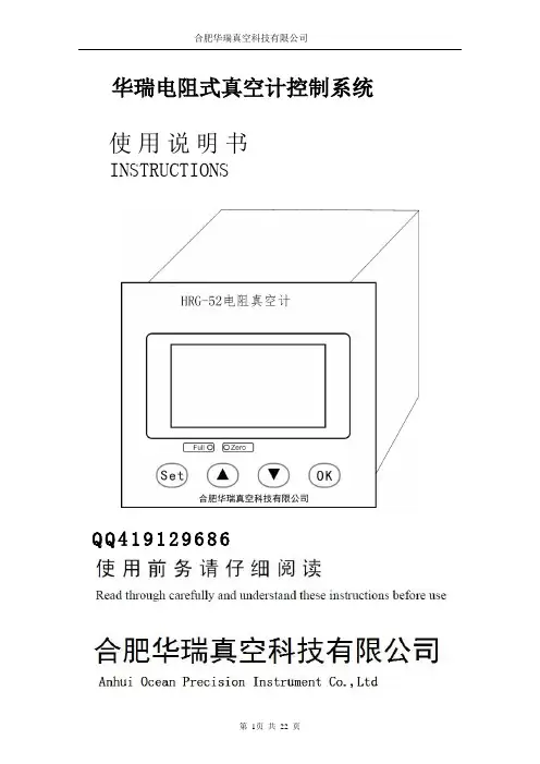
1、复合真空计使用说明1.1 主要性能:1.1.1 本复合真空计由一个热偶计和一个宽量程的复合真空计构成.热偶采用单一的一支ZJ—54D 热偶规管进行测量。
复合真空计用一支ZJ-54D 热偶规和一支ZJ-10 电离规进行测量。
1.1.2 测量范围:热偶计:103Pa~10-1Pa复合计:103Pa~10-4Pa 。
其中电离规3.5Pa~10-4Pa。
1.1.3 本复合真空计配有RS232 接口,可与带相应接口的计算机联机。
测量数据由计算机进行管理。
1.1.4 供电:本复合真空计采用单相220V 交流供电。
电压范围:220V AC±10%;消耗功率:≤30W1.1.5 使用和储存环境:温度:5℃~35℃湿度:0~85 %严禁在高温潮湿和有腐蚀性气体的环境下工作和储存。
严禁在工作时猛烈碰撞。
1.1.6 机箱尺寸:宽×高×深=480×119×320重量:约7Kg1.1.7 出厂时规管引线均为5m。
最长建议不要长于10m。
1.1.8 RS232 接口建议采用屏蔽电缆。
屏蔽线与机壳相连,并接地。
1.1.9 电离规的启动方式:由面板上的自动、手动开关控制。
自动方式下,热偶规测量值<3.5Pa时接通,>4.0Pa 时关闭。
手动方式下,由面板上的二个ON和OFF按纽控制。
当真空度大于10Pa时,请不要打开电离规。
2.操作说明:本复合真空计是采用单片机技术的智能化仪器。
打开电源后,真空计初始化显示“HZ HZ HZ HZ”初始化完后,热偶计直接进入工作状态。
没有接入规管或规管暴露在大气中时,都是显示103Pa。
复合计:分手动和自动启动方式,在面板上,设有电离规状态指示灯。
电离规关闭或没接或故障时,ZJ-10 指示灯亮。
在手动方式下,在没有接通电离规之前,若热偶规正常,则指示热偶规测量的真空值。
接通电离规后,显示的是电离规测量的真空度。
电离规测量值≥5.0Pa 时,自动关闭电离规灯丝。
操作手册反磁控皮拉尼真空计MPG400MPG401tina48e1-a (2006-12) 1产品标识与INFICON公司联系时,请告知产品名牌上的信息. 为便于参考,请将产品信息填入下列空格中:有效性本文件适用于下列件号的产品:件号(PN)可从产品的名牌上看到.如图例中未特别标明,本文插图中相应的产品件号351-010. 类似应用于其它产品.我们保留不事先通知技术修改的权利.全部尺寸为毫米.用途基本原理反磁控皮拉尼真空计MPG400和MPG401用于压强范围为5×10⁻⁹… 1000毫巴的真空测量.切勿将反磁控皮拉尼真空计用于测量与空气产生反应的易燃或易爆性气体.真空计可与单通道控制器VGC401,双通道控制器VGC402和三通道控制器VGC403或其它适当的仪器连接使用.在整个测量范围内,测量讯号输出为对数压强讯号.真空计包含两个单独的测量系统(皮拉尼和反磁控原理的冷阴极系统). 为用户方便,复合成一个测量系统.m2 tina48e1-a (2006-12) MPG400-401.o目录产品标识2有效性2用途2基本原理21 安全41.1 使用符号41.2 人员要求41.3 一般安全规则41.4 责任和保用42 技术参数53 安装83.1 真空连接83.1.1 拆卸磁铁单元(仅用于带CF法兰的真空计)103.2 电连接113.2.1 与INFICON真空计控制器一起使用113.2.2 与其它控制器一起使用114 运行124.1 测量原理, 测量性能125 卸装146 维护156.1 真空计调整156.2 清洗MPG400, 更换部件176.2.1 拆卸MPG400176.2.2 清洗MPG400186.2.3 重新组装MPG400196.3 清洗MPG401, 更换部件206.3.1 拆卸MPG401216.3.2 清洗MPG401226.3.3 重新组装MPG401236.4 故障查找247 附件258 备件259 产品返回2710 废物处理27附录28A:测量讯号与压强的关系28B:与气体类型的关系29污染申报表 31本文中的相互参照,使用符号(XY).tina48e1-a (2006-12) MPG400-401.om 3防止任何危及人身安全的信息1.2 人员要求本说明书中所述的全部工作必须由经过技术培训和有经验或由产品的最终用户1.3 一般安全规则1.4 责任和保用•遵守适当的规程和对所用的过程介质采取必要的防护措施.考虑产品材料(7)与过程介质之间可能引起的反应.考虑由于产品产生的热与过程介质之间可能引起的反应(例如爆炸).•遵守适当的规程和对全部您要做的工作采取必要的防护措施.,并遵守本文件中的安全规定.•在工作开始前,找出是否任何真空元件已污染. 遵守相关的规程和对污染部件采取必要的防护措施..将安全规则通知全部其它用户.INFICON不再承担任何责任和保用, 如用户或第三方:•无视本文件中的信息•不适当的方式使用产品•对产品进行任何种类的介入(修改,变更等.)•使用未列入产品文件中的附件.最终用户对使用的过程介质承担全部责任.真空计由于污染损坏,以及易耗件(灯丝),不包括在保修范围内.m4 tina48e1-a (2006-12) MPG400-401.otina48e1-a (2006-12) MPG400-401.om 5测量范围(空气, N 2) 5×10⁻⁹ … 1000 毫巴 精度 (N 2) ≈±30%在1×10⁻⁸ … 100毫巴范围内 再现性≈±5%在1×10⁻⁸ … 100毫巴范围内 与气体类型的关系→ 附录B输出讯号 (测量讯号) 电压范围 0 … +10.5 伏 测量范围 1.82 … 8.6 伏 电压与压强的关系对数, 0.6 伏 / 量级 (→ 附录 )误差讯号 <0.5 伏 无电源>9.5 伏 皮拉尼测量元件损坏(灯丝断)输出阻抗 2×10 Ω最小负载电阻 10 k Ω , 短路保护 响应时间 (与压强有关) p > 10-6 毫巴 p = 10-8 毫巴<10 毫秒 ≈1000 毫秒规管标识85 k Ω与电源公共点之间状态脚6p > 10-2 毫巴 仅皮拉尼模式 低 = 0 V p < 10-2 毫巴 冷阴极未引燃 仅皮拉尼模式p < 10-2毫巴冷阴极引燃皮拉尼/冷阴极复合模式 低 = 0 V高 = 15 … 30 VDC指示灯高压 on (LED on)电源与真空计规管连接的电源真空计的工作电压 15.0 … 30.0 VDC (纹波 ≤ 1 V pp ) 功耗 ≤2 瓦保险丝1)≤1 AT最小电源电压必须随传感器电缆的长度而增大.最大电缆长度的电源电压16.0 … 30.0 VDC (纹波 ≤ 1 V pp )1)INFICON 控制器能满足这些要求.6tina48e1-a (2006-12) MPG400-401.o调整<HV>电位器在 <10-4 毫巴下 m<ATM>电位器在大气压下电连接件 FCC68 插座型, 8 脚 传感器电缆 8 导线 + 屏蔽 电缆长度≤50 米 (8×0.14 毫米²)工作电压 ≤3.3 仟伏 工作电流≤500 微安接地概念→ ("电连接")真空连接 - 讯号公共通过10 k Ω连接(最大电压差从安全考虑 ±50 V 从精度考虑 ±10 V) 电源公共 - 讯号公共 单独通导暴露于真空中的材料 真空连接件 测量室 馈入件 内部密封MPG400 MPG401 阳极引燃辅助极 皮拉尼测量管 皮拉尼灯丝不锈钢 不锈钢 陶瓷FPM 75Ag, Cu, 软焊剂(Sn, Ag) Mo 不锈钢 Ni, Au W安装方位 任意内容积 ≈20 厘米³ 压强≤10 巴 (绝对) 限于惰性气体温度工作MPG400 MPG401+5 … +55 °C +5 … +150 °C(在法兰处水平方位安装,无磁屏蔽)烘烤 +150 °C(无磁屏蔽和电子学单元) 皮拉尼灯丝 +120 °C 贮存–40 °C … +65 °C相对湿度 ≤80% 温度高至+31 °C 时降至 50% 温度+40 °C 时使用仅室内海拔高至2000米保护类型 IP 40尺寸[毫米] 重量351-010 ≈700克351-011 ≈720克351-012 ≈980克351-020 ≈730克351-021 ≈750克351-022 ≈1010克tina48e1-a (2006-12) MPG400-401.om 78tina48e1-a (2006-12) MPG400-401.om3.1 真空连接危险: 真空系统中的过剩压力危险: 保护接地规管可任何方位安装. 为防止来自测量室的凝聚物和微粒, 最好选择水平 向上的位置和使用带有对中环与过滤件的密封件.tina48e1-a (2006-12) MPG400-401.om 9如规管安装后需要进行调整, 则必须确保可用螺丝刀进入调节<HV>和<ATM>微调电位器(15).顺序卸下保护盖和将产品安装上真空系统.当使用CF 法兰连接时,最好临时卸下磁铁单元(10).带对中环的密封件或保护盖夹环将保护盖保存好.带对中环和过滤件 的密封件3.1.1卸下磁铁单元(仅用于带CF法兰的规管)需用工具顺序•通用扳手 1.5 毫米•开口扳手 7.0 毫米a) 拧下电子学单元(2)上的六角凹头螺钉(1).b) 卸下电子学单元,不要扭转它.c) 拧下磁铁单元(4)上的六角头螺钉(3)和卸下磁体单元.磁力和倾斜趋向使磁体难于与测量室(7)分离.d) 将规管与真空系统间的法兰连接上.e) 重新装上磁体单元,并用六角头螺钉(3)锁紧它.f) 小心地装上电子学单元(2). (确保皮拉尼规管的插脚正确地插入电子学单元的相应的孔中).g) 向上推电子学单元至机械限位器,用六角凹头螺钉(1)锁紧它.m10 tina48e1-a (2006-12) MPG400-401.o3.2 电连接前提3.2.1 与INFICON 控制器一起使用3.2.2 与其它控制器一起使用确保真空连接已妥善完成(→ 8).将传感器电缆连接至规管和控制器.按下图制作一根传感器电缆.讯号10 k6 10 3 + 105 –标识4 1 + 2–电连接 脚 1 电源 (15 … 30 VDC ) 脚 2 电源公共 脚 3讯号输出(测量讯号)脚 4 标识 脚 5 讯号公共脚 6状态 脚 7, 8 n.c.FCC68, 8脚 连接件将传感器电缆连接规管和控制器.一旦加上所需的电源电压,脚3与脚5间即有测量讯号. (→附录查阅有关测量讯号与压强之间的关系).需约10分钟的稳定化时间. 一旦真空计接通电源, 在任何压强下始终保持电源on的状态.4.1 测量原理,测量性能真空计包含两个单独的测量系统(皮拉尼和反磁控原理的冷阴极系统). 为用户方便,复合成一个测量系统.采用最佳的测量配置于特定的压强范围, 在这个范围内执行测量:10-4 毫巴1000 毫巴冷阴极皮拉尼5×10⁻⁹ 毫巴10-2 毫巴•皮拉尼测量电路始终处于接通的状态•冷阴极电路由皮拉尼电路控制,仅在压强<1×10⁻² 毫巴时接通工作标识输出(脚 6) 指示真空计当前的状态:压强规管的指示灯工作模式脚6p > 1×10⁻² 毫巴仅皮拉尼模式低 =0 Vp < 1×10⁻² 毫巴p < 1×10⁻² 毫巴冷阴极未引燃仅皮拉尼模式冷阴极已引燃复合的皮拉尼 / 冷阴极模式低 =0 V高= 15 … 30 VDC在冷阴极测量电路未引燃时, 皮拉尼的测量值输出为测量讯号(如p < 5×10⁻⁴ 毫巴,将出现"皮拉尼欠量程"的显示).与气体类型的关系引燃延迟测量讯号与被测量的气体类型有关. 曲线对干燥空气, O2, CO和N2是正确的. 对其它气体可进行转换(→附录 B).如使用 INFICON 控制器, 则可键入一个校准因素校正压强读值(→ 控制器的).当冷阴极测量系统接通工作时, 将出现引燃延迟. 随着压强的降低,延迟时间将加长, 典型数据如下:10-5 毫巴≈1 秒10-7 毫巴≈20 秒5×10⁻⁹ 毫巴≈2 分在冷阴极测量电路未引燃时,皮拉尼的测量值输出为测量讯号(如p < 5×10⁻⁴ 毫巴,将出现"皮拉尼欠量程"的显示). 标识输出(脚6, 低) 指示为仅皮拉尼模式.如真空计在压强 p < 3×10⁻⁹ 下接通工作,真空计不能辨别冷阴极系统是否引燃. 它将指示"皮拉尼欠量程".一旦电源on,可在任何压强下始终保持真空计于工作模式. 此时,可始终忽略冷阴极电路的测量延迟(<1 秒),和热稳定效应最小化.污染由于污染引起的真空计故障,以及易耗件(灯丝),不属于保修范围内.由于所用的过程介质以及任何存在,或新污染物及其相应的分压强,将导致真空计污染.连续运行于10-4 毫巴 … 10-2 毫巴下可导致严重污染以及降低正常运行时间和维护周期. 保持于低压强下(p <1×10⁻⁶ 毫巴), 真空计可运行一年以上无需清洗(清洗真空计→17, 20).真空计的污染通常导致测量值的偏差:•在高压强范围(1×10⁻³ 毫巴… 0.1毫巴),压强读值过高(皮拉尼元件被污染). 重新调整皮拉尼测量系统→15.•在低压强范围(p < 1×10⁻³ 毫巴), 压强读值通常过低(冷阴极系统被污染). 在严重污染的情况下,可出现不稳定(测量室的构层剥落). 由于绝缘层的剥落产生的污染可导致放电的全面故障(将显示"欠量程").采取下列措施,可在一定程度上减少污染:•几何结构上的保护措施(例如屏筛,肘管),用于线性散布的微粒•将规管法兰安装于污染分压特别低的部位.尤其要警惕的是在等离子下的蒸汽淀积(对于冷阴极测量系统). 当这类蒸汽出现时,甚至需暂时关断真空计.危险: 污染的部件顺序将真空系统放空.将规管退出运行和卸下传感器电缆.从真空系统上卸下规管,并盖上保护盖.当拆卸CF法兰连接件时, 最好临时卸下磁铁单元(→10).保护盖由于污染引起的真空计故障,以及易耗件(灯丝),不属于保修范围内. 危险: 污染的部件6.1 调整真空计需用工具顺序真空计规管是出厂前校准的. 由于使用于不同的气候条件,极端的温度,老化或污染和更换规管后,可发生特性曲线的偏移,从而再调整是必要的.冷阴极测量电路, 主要用于低压强测量(<1×10⁻³ 毫巴), 是出厂前校准的不能再调整. 与它对比,皮拉尼测量电路是可调整的. 任何调整在压强范围约10-2 毫巴至102 毫巴之间有一个可忽略的效应.•螺丝刀 1.5 毫米•圆柱管丝锥ø≈3 毫米如使用带对中环和过滤件的密封件, 检查它们是否清洁,必要时更换(→14).将真空计投入运行(如可能,在即将使用的位置上).将真空系统抽空至 p << 10-4 毫巴,随后等待10 分钟.逆时针方向旋转铭牌直至达到机械限位器.用圆柱管丝锥压下销针,调节<HV>电位器 …… 至 4.20 伏或…至 5×10⁻⁴ 毫巴.随后,逆时针方向旋转电位器1/3圈用空气或氮气将规管放空至大气压,并至少等待10分钟.顺时针方向旋转铭牌直至达到机械限位器.使用 1.5 毫米螺丝刀, 调整 <ATM> 电位器 …… 至 8.60 伏或 … 至 1×10³ 毫巴.旋转铭牌回到它的原先位置(扣住).6.2 清洗MPG400,更换部件当使用清洗剂和处理它们时必须遵守相关的规程和采取必要的措施→ 6).我们建议当清洗规管时,更换皮拉尼元件.需用工具 / 材料6.2.1 拆卸MPG400• 通用板手 AF 1.5 • 通用板手 AF 3 • 开口扳手 7.0 毫米 • 钳子,用于开口簧环• 抛光布(400粒度) 或Scotch-Brite(纤维布) • 镊子 • 清洗用酒精• 引燃辅助极的安装工具 • 引燃辅助极• 皮拉尼元件(13)包含FPM 密封圈(13a) •FPM 密封圈(11)用于阳极馈入件从真空系统上卸下规管(→14).拧下电子学单元(2)上的六角凹头螺钉(1).卸下电子学单元,不要扭转它.电子学单元的外壳不能卸下.拧下磁铁单元(4)上的六角头螺钉(3),并卸下磁铁单元.磁力和倾斜趋向使磁体难于与测量室(7)分离.从测量室上取下开口簧环(5)和极性插件(6).从测量室后面卸下三个六角头螺钉(8)包括锁紧垫圈(8a).小心地按此顺序卸下下列部件(无应力施加于皮拉尼元件(13)上): 压块(9),整个阳极(10), FPM 密封件(11)包括支撑环(12),皮拉尼元件(13)包括FPM 密封件(13a).现可逐个清洗或更换部件.6.2.2 清洗MPG400清洗测量室和极性插件清洗或更换阳极用抛光布擦净测量室的内壁与极性插件至光亮的程度.密封表面必须按同心圆方式擦净.用清洗酒精漂洗测量室和极性插件.使它们干燥.用钳子取下用过的引燃辅助极(10a).用抛光布擦洗阳极杆至光亮的程度.切勿弯曲阳极. 切勿在陶瓷件上进行机械作业.用清洗酒精漂洗阳极.使阳极干燥.在安装工具上插入新的引燃辅助极(10a).小心地压阳极(清洁的或新的)居中工具轴和并行地插入引燃辅助极至约15 毫米深度. 最终定位在阳极安装后.阳极引燃辅助极安装工具清洗皮拉尼元件更换皮拉尼元件6.2.3重新组装MPG400从皮拉尼元件(13)上取下FPM密封件(13a).用清洗酒精注入皮拉尼测量管中,并晃动.就酒精从管中倒出.将管干燥(例如使用吹风机 <150 °C).将新的FPM密封件(13a)套入皮拉尼元件,插入相应的凹槽中.重新安装皮拉尼元件(→19).如严重污染或损坏.将新的FPM密封件(13a)套入皮拉尼元件,插入相应的凹槽中.安装皮拉尼元件(→19).(→图17)用支撑环(12)将FPM密封件(11)居中地插入测量室(7). 密封表面,密封件,和陶瓷件必须清洁.小心地将阳极(10)包括引燃辅助极(10a)插入测量室中.将FPM密封件(13a)套入皮拉尼元件(13),插入相应的凹槽中.小心地将压块(9)放在测量室上用三个六角头螺钉(8)包括锁紧垫圈(8a)均匀地拧紧直至达到限位器.在阳极杆的上方推安装工具,定位引燃辅助极(10a)直至达到机械限位器.用干燥氮气吹净测量室中的微粒(小心地拿住法兰朝下的测量室).将极性插件(6)滑入测量室中,直至达到机械限位器.将开口簧环(5)紧贴地适配于极性插件上.目测针状阳极是否居中地穿过极性插件的中心孔(最大偏心度= 0.5 毫米).如可能,执行一次漏率测试(漏率<10-9 毫巴·升/秒).装上磁铁单元(4)并用六角头螺丝(3)锁紧它.小心地安装电子学单元(2). (确认皮拉尼单元的插脚正确地插入电子学单元相应的孔中).推上电子学单元至机械限位器,并用六角凹头螺钉(1)锁紧它.调整真空计(→15).6.3 清洗MPG401,更换部件当使用清洗剂和处理它们时必须遵守相关的规程和采取必要的措施→ 6).为清洗测量室,皮拉尼单元必须卸下和更换.需用工具/ 材料•通用扳手 AF 1.5•通用扳手 AF 3•开口扳手 AF 6•开口扳手 AF 7•钳子,用于开口簧环•抛光布(400粒度) 或Scotch-Brite(纤维布)•镊子•清洗用酒精•引燃辅助极的安装工具•引燃辅助极•金属密封件(11)用于阳极馈入件•皮拉尼元件(13)包括成套密封件(13a, 13b)6.3.1拆卸MPG401从真空系统上卸下真空计(→14).拧下电子学单元上(2)的六角凹头螺钉(1).卸下电子学单元,不要扭转它.电子学单元的外壳不能卸下.拧下磁铁单元(4)上的六角头螺钉(3),并卸下磁铁单元.磁力和倾斜趋向使磁体难于与测量室(7)分离.从测量室上取下开口簧环(5)和极性插件(6).拧下六角凹头螺钉(9c)和卸下绝缘件(9b),不要扭转它.从测量室后面卸下四个六角凹头螺钉(8)包括锁紧垫圈(8a).小心地按此顺序卸下下列部件(无应力施加于皮拉尼元件(13)上): 压块(9),阳极延伸杆(9a),整个阳极(10),金属密封件(11)包括对中环(12).拧下皮拉尼元件的螺丝接头(13a),并卸下带有铜密封件(13b)的皮拉尼元件.现可逐个清洗或更换部件.6.3.2清洗MPG401清洗测量室和极性插件清洗或更换阳极用抛光布擦净测量室的内壁和极性插件至光亮的程度.密封表面必须按同心圆方式擦净.用清洗酒精漂洗测量室和极性插件.使它们干燥.用钳子取下用过的引燃辅助极(10a).用抛光布擦洗阳极杆,至光亮的程度.切勿弯曲阳极. 切勿在陶瓷件上进行机械作业.用清洗酒精漂洗阳极.使阳极干燥.在安装工具上插入新的引燃辅助极(10a).小心地压阳极(清洁的或新的)居中工具轴和并行地插入引燃辅助极至约15 毫米深度.最终定位在阳极安装后.更换皮拉尼元件将螺丝接头(13a)和铜密封件(13b)套入皮拉尼元件(13).装上皮拉尼元件(→23).6.3.3重新装配MPG401(→图21)将带螺丝接头(13a)和铜密封件(13b)的皮拉尼元件(13)插入测量室的相应圆锥形钻孔(7)中.用手指拧紧螺丝接头(13a)的同时轻微地将皮拉尼元件推向机械电位器. 然后用开口扳手拧紧螺丝接头一圈.将新的金属密封件(11)包括对中环(12)居中地插入测量室(7).小心地将阳极(10)包括引燃辅助极(10a)和延伸杆(9a)插入测量室中.小心地将压块(9)放在测量室上.用四个六角凹头螺钉(8)包括锁紧垫圈(8a)均匀地拧紧它们直至达到限位器.小心地将绝缘件(9b)置于压块(9)上,并用六角凹头螺钉(9c)锁紧它.在阳极杆的上方推安装工具,定位引燃辅助极(10a)直至达到机械限位器.用干燥氮气吹净测量室中的微粒(小心地拿住法兰朝下的测量室).将极性插件(6)滑入测量室中,直至达到机械限位器.将开口簧环(5)紧贴地适配于极性插件上.目测针状阳极是否居中地穿过极性插件的中心孔(最大偏心度= 0.5 毫米).如可能,进行一次漏率测试(漏率 <10-9 毫巴·升/秒). 必要时轻微地再次上紧螺丝接头(13a).装上磁铁单元(4)并用六角头螺丝(3)锁紧它.小心地安装电子学单元(2). (确认皮拉尼单元的插脚正确地插入电子学单元相应的孔中).推上电子学单元至机械限位器,并用六角凹头螺钉(1)锁紧它.调整真空计(→15).6.4 故障查找问题可能原因 解决方法 测量讯号持续< 0.5V "误差低".无电源电压.将电源置于on.皮拉尼测量单元损坏 (灯丝断裂).更换皮拉尼元件 (MPG40019) (MPG40122). 测量讯号持续> 9.5V "误差高".电子学单元未正确安装.正确安装电子学单元 (MPG40019) (MPG40123). 冷阴极放电未引燃.等待直到气体放电引燃 (在绝缘层污染的情况下, 冷阴极完全不能引燃). (清洗MPG40017 MPG40120). 绿色指示灯ON 和标识指示仅皮拉尼模式(测量讯号持续> 4.0V)"皮拉尼欠范围".MPG 仅能工作于压强 p < 3x10—9 毫巴.稍升高些压强.皮拉尼测量电路未调整, 例如由于严重污染. 重新调整皮拉尼测量电路(15).如不可能调整,更换皮拉尼元件.测量讯号持续>5V 或 显示>10-3毫巴,虽然真空压强OK. 测量重气体.用相应的公式转换(29). 在冷阴极测量室内严重的出气.清洗测量室.测量讯号不稳定.规管污染.清洗规管 (MPG40017) (MPG40120).订购附件时, 始终提及:•产品铭牌上的全部信息•附件清单上的名称与订货号名称订货号磁屏蔽件 BG443155-X订购备件时, 始终提及:•产品铭牌上的全部信息•备件清单上的名称与订货号项号名称MPG400 订货号1213a1110a131213a1110a1010a维护成套件,包含:1× 支撑环1× O-圈 FPM ø3.69×1.781× O-圈 FPM ø10.82× 1.783× 引燃辅助极检修成套件,包含:1× 皮拉尼元件1×支撑环1× O-圈 FPMø3.69×1.781× O-圈 FPM ø10.82×1.783× 引燃辅助极1× 阳极,整件成套引燃辅助极,包含:10× 引燃辅助极引燃辅助极的安装工具351-999351-998351-995351-994BN846469-TBN846470-TBN846471-T 测量系统DN 25 ISO-KF法兰DN 40 ISO-KF法兰DN 40 CF-F法兰项号名称订货号11 12 10a13 13a 13b 9a 10 10a11 1210a维护成套件,包含:1×密封件 HNV 100 (9×1.6) 1× 对中环3× 引燃辅助极1×垫圈 (未用于MPG401)Repair set, consisting of: 1× 皮拉尼元件,带玻璃馈入件 1× 螺丝接头 1× 铜密封件 1× 阳极延伸杆 1× 阳极,整件 3× 引燃辅助极 1× 密封件 HNV 100 (9×1.6) 1× 对中环成套引燃辅助极,包含:10× 引燃辅助极引燃辅助极的安装工具351-997351-996351-995351-994BN846472-T BN846473-T BN846474-TMPG401测量系统,整件 DN 25 ISO-KF 法兰 DN 40 ISO-KF 法兰 DN 40 CF-F 法兰检修成套件,包含:31).无明确的”无危害性物质”申报的产品,全部去污染费用由客户承担. 未附有完整污染申报表的产品将退回发送方,费用由发送方承担.危险: 污染的部件N元件分类污染的元件其它元件产品拆卸后, 按下列标准将其元件分类:污染的产品(如放射性,毒性,腐蚀性或微生物危害等)必须按相关的国家规定去污染,按照它们的材料分类,和处理.必须按它们的材料将这些元件分类和回收.A:测量讯号与压强的关系转换公式p = 101.667U-d⇔U = c + 0.6log10pp U c d[毫巴] [乇] [帕][伏][伏][伏]6.86.8755.611.3311.469.333其中p压强U测量讯号c,d常数(与压强单位有关)有效范围5×10⁻⁹毫巴<p<1000毫巴3.8×10⁻⁹乇<p<750乇5×10⁻⁷帕<p<1×10⁵帕转换曲线压强p测量讯号U[伏]转换表测量讯号 U [伏] 压强 p [毫巴] 压强 p [乇] 压强 p [帕]<0.5 传感器误差0.5 … 1.82 欠量程1.822.02.63.23.84.45.05.66.26.87.48.0 8.65.0×10-91.0×10-81.0×10-71.0×10-61.0×10-51.0×10-41.0×10-31.0×10-20.11.01010010003.8×10-97.5×10-97.5×10-87.5×10-77.5×10-67.5×10-57.5×10-47.5×10-37.5×10-40.757.5757505.0×10-71.0×10-61.0×10-51.0×10-41.0×10-31.0×10-20.11.01010010001.0×1041.0×1058.6 … 9.5 过量程9.5 … 10.5 传感器误差(皮拉尼损坏)B: 与气体类型有关指示范围 高于10-2毫巴指示的压强 (对空气校准的真空计).p (10286 421018 6 42100 8 6 4210–1 8 6 4210–212 810–2810–110081012 p ef f (毫巴)指示范围10-6 … 0.1毫巴指示的压强 (对空气校准的真空计).p (毫巴)10–18 6 410–28 6 4210–38 6 428 6 4210–586 4210–6810–5810–4810–3810–2–1p ef f (毫巴)指示范围低于10-5毫巴在低于10-5毫巴范围内,压强指示是线性的. 对空气以外的其它气体,可用简单的转换公式来确定压强:p eff= K × 指示的压强其中气体类型K空气(O2, CO, N2) 1.0Xe0.4Kr0.5Ar0.8H2 2.4Ne 4.1He 5.9这些转换因素为平均值.通常涉及的是气体与蒸气的混合物. 在此情况下,只有用分压强测量仪器,即四极质谱仪才能精确地确定.tina48e1-a (2006-12) MPG400-401.om 31真空设备和元件的服务,检修和/或处理必须提供正确完整的申报表. 不完整将导致延迟的后果.本申报表必须由经授权和有资格的人员填写(大写)和签署.产品说明型号返修原因编号出厂号 使用的工作液体 (在发运前必须放空)产品的污染过程:毒性 否 是腐蚀性 否 是生物危害性 否 是易爆性 否 是放射性 否 是其它有害性物质 否 是 或不包含超过允许限量的任何危害性残余物 产品无任何损害健康的物质.是未明确写明去污染的 污染产品将不予受理!有害的物质,气体和/或副产品请列出与设备接触过的物质,气体和副产品:商标/产品名称 化学名称(或符号)应采取预防的措施 人体接触的急救方法有法律约束的申报:我们谨此申明本申报表中的信息是完整和正确的,并承担任何可能支付的费用. 污染的产品将按相应的规定发运.机构/公司名称地址 邮政编码,地区电话 传真电子邮件姓名日期和有法律约束的签名公司盖章曾用于铜过程否 是 将产品封闭在塑料袋中,并用标签标志..LI–9496 BalzersLiechtensteinTel +423 / 388 3111Fax +423 / 388 3700 Original: German tina48d1-a (2006-12)reachus@ t i na48e1-a。
WPI-200 Pirani Gauge with Build-in ControllerWe are not only a gauge Operating Manual● Standalone Vacuum Meter5-Digit LED Display Programming Keys 2 Setpoint Control Switches Analog Voltage Output● RS485 CommunicationAddress for 16 Nodes● Wireless Communication100m DistanceWireless Network with 16 NodesTable of ContentsAbout WPI-200Product Identification 3 Validity 3 Intended Use 4 Functional Principle 4 1 Safety 5 1.1 Symbols Used 5 1.2 Personnel Qualifications 5 1.3 General Safety Instructions 5 1.4 Liability and Warranty 6 2 Technical Specifications 7 2.1 Datasheet 7 2.2 D-Sub 9 Connector Pin Assignment 8 2.3 Analog Signal Output 9 2.4 Setpoint Control Switches 10 2.5 Gas Type Dependence 11 3 Installation and Operation 12 3.1 Vacuum Connection 12 3.2 Electrical Connection and Operation 14 3.2.1 Standalone Mode 14 3.2.2 Use with INSTRUE WGC-150 Vacuum Gauge Controller 16 3.2.3 Use with Analog Signal Converter 18 3.2.4 Use with RS485 Communication 19 3.2.5 Use with Wireless Communication 21 3.2.6 Gauge Reader Application Software 22Install USB transceiver driver 22 Install INSTRUE “Gauge Reader 2.0” 23 Start using GaugeReader 243.2.7 RS485\Wireless Communication Protocols 25 4 Maintenance and Troubleshoot 274.1 Maintenance 27 4.2 Atmospheric Pressure Calibration 27 5 Troubleshooting and Replacement 28 6 Options and Spare Parts 29 7 Returning the Product 29 8Disposal29Product IdentificationIn all communications with INSTRUE, please specify the information given on the product nameplate. For convenient reference copy that information into the space provided below.ValidityThis document applies to products of the WPI-200 series.The postfixes of TYP for the standard products are indicated below. OEM products have specific types and different parameter settings as defined in the corresponding ordering information.The serial number (S.N.) can be taken from the product nameplate.Pirani None: KF25 A: KF16 B: CF35 or OEM CodeIntended UseThe Pirani Gauge Controller WPI-200 has been designed for vacuum measurement of gases in the pressure range of 1.0×10⁻¹ ~1.0×10+5 Pa.It must not be used for measuring flammable or combustible gases which react in air. The gauge is intended for operation independentlyOR in connection with an INSTRUE Vacuum Gauge Controller WGC150,OR in connection with a standard computer through RS485 transceiver,OR in data communication with a standard computer through an INSTRUEUSB transceiver module WFTC-001.Functional PrincipleThe WPI-200 gauge contains of a fine heated tungsten wire (also called a filament) suspended in a gas which will lose heat to the gas as its molecules collide with the wire and remove heat. If the gas pressure is reduced, the number of molecules present will fall proportionately and the wire will lose heat more slowly. Measuring the heat loss is an indirect indication of pressure. The electrical resistance of a wire varies with its temperature, so the resistance indicates the temperature of wire. In WPI-200, the wire is maintained at a constant resistance R by controlling the current I through the wire. The resistance can be set using a bridge circuit. The power delivered to the wire is I2R, and the same power is transferred to the gas. The current required to achieve this balance is therefore a measure of the vacuum.The gauge can display the vacuum pressure by a 5-digit LED, or communicate with a standard PC through RS485 or Wireless, as well it outputs an analog signal as a logarithm of the pressure over the whole measurement range, and it has two build-in setpoint switches.1 Safety1.1 Symbols Used1.2 Personnel Qualifications1.3 General Safety Instructions• Adhere to the applicable regulations and take the necessary precautions for the process media used.Consider possible reactions with the product materials.Consider possible reactions (e.g. explosion) of the process media due to the heat generated by the product.• Adhere to the applicable regulations and take the necessary precautions for all work you are going to do and consider the safety instructions in this document.• Before beginning to work, find out whether any vacuum components are contaminated. Adhere to the relevant regulations and take the necessary precautions when handling contaminated parts.Communicate the safety instructions to all other users.Information on preventing any kind of physical injury.Information on preventing extensive equipment and environmental damage.Information on correct handling or use. Disregard can lead to malfunctions or minor equipment damage.All work described in this document may only be carried out by persons who have suitable technical training and the necessary experience or who have been instructed by the end-user of the product.1.4 Liability and WarrantyINSTRUE assumes no liability and the warranty becomes null and void if the end-user or third parties• disregard the information in this document• use the product in a non-conforming manner• make any kind of interventions (modifications, alterations etc.) on the product• use the product with accessories not listed in the product documentation.The end-user assumes the responsibility in conjunction with the process media used. Gauge failures due to contamination as well as expendable parts (filament) are not covered by the warranty.2 Technical Specifications 2.1 DatasheetParameter SpecificationsMeasurement range (air, N2) 1.0×10⁻¹ ~1.0×10+5 PaAccuracy 1.0×10⁻¹ ~1.0×10+4 Pa : ±15% 1.0×10+4 ~1.0×10+5 Pa : ±50% Repeatability1.0×10-1 ~1.0×10+3 Pa : ±5% 1.0×10+3 ~1.0×10+5 Pa : ±25% Maximum Pressure(absolute) 1.5×10+5 Pa Measuring Cycle100 msProbe Bake-out Temperature 150º C Max. (300º C Max. for CF type vacuum connector) Ambient Temperature(Operation) 0º C ~ +45º C Ambient Temperature(Storage) -40º C ~ +75º CAmbient Humidity (Operation)5 ... 85 %, non-condensingPressure Reading5-digital LED display, with Pa, Torr, mBar unit selection RS485 (non-isolated) at baud rate of 9600 bpsWireless communicate with PC through INSTRUE USB Wireless transceiver WFTC-001Connection with INSTRUE vacuum gauge controllerWGC150Analog output of +2.5V~+8.5V , min. impedance of 10ΩSetpoint Control 2 set-points, optical isolated open collector output Power Supply+24VDC (±20%) /1.5A, via D-Sub9 connector Maximum Power Consumption 2.0WProtection Class IP40 according to IEC529Vacuum Connection Default: DN 16 ISO-KF; Option for others Weight300g (standard KF16 flange)Dimensions 100H X 50W X 32D (including KF16 flange) Materials Exposed to VacuumSS304, SS316L, Kovar 4J50, Filament W, feedthroughglass,The gauge may only be connected to supply or measurement units that conform to the requirements of a grounded protective extra-low voltage . The connection to the gauge has to be fused by 0.5AT.We reserve the right for modification to this technical data without prior notice!1234567892.2 D-Sub 9 Connector Pin AssignmentD-Sub 9 Pin, Male, Plug-In SideElectrical Connection Pin 1 Supply Common GND Pin 2 Setpoint Output A Pin 3 Setpoint Output B Pin 4 Analog V oltage Output Pin 5 RS485 DATA- (B) Pin 6 Supply +24VDC Pin 7 Setpoint Common Pin 8 Analog GND AGND Pin 9RS485 DATA+ (A)Pay attention to the difference of D-Sub 9 connector: Female, Male, Soldering Side, Plug-In Side.2.3 Analog Signal OutputD-Sub 9 Connector Pin4/Pin8 delivers analog voltage which is related to the “real-time” pressure.The measurement signal ranges from +1.8V to +10.0VDC, 2.5mV resolution.1.0E-081.0E-071.0E-061.0E-051.0E-041.0E-031.0E-021.0E-011.0E+001.0E+011.0E+021.0E+031.0E+041.0E+05Output Signal U (Volt)WhereP : Pressure U : V oltage (V)c: Constant(Pressure Unit Dependent)U P C (V) Pa 1.0 (V) mBar 0.6 (V) Torr 0.575P=10(U-3.5)cU=3.5+(lgP)/c2.4 Setpoint Control SwitchesWPI-200 has two independent settable switching functions. They can be manually set up via keys on the top. As well, the two setpoints are accessible through RS485 or Wireless communication commands.The threshold values of switching functions A and B can be set within the pressure range of 1.1E-1 Pa to 9.9E+4 Pa.The setpoint is defined as the pressure at which point the optical coupler switches ON, the setpoint output pin is driven to LOW. At the pressure lower than the setpoint the optical coupler stays ON. When the pressure raise up to 110% of setpoint, the optical coupler goes to OFF. It is called hysteresis control.2.5 Gas Type DependenceFor the Pirani sensor, the pressure measurement is dependent on the gas type. All the gauge probes are factory set for operation with dry air/N2.3. Installation and Operation3.1 Vacuum ConnectionMounting orientation The installation position can be freely selected. The preferred position is a horizontal to vertical position so that condensate and particles do not penetrate the measurement chamber.ProcedureStep 1. Remove the protective cover and keep it for maintenance use.When handling vacuum components, take appropriatemeasures to ensure cleanliness and prevent damages. Ensure that the flange is clean, dry and free of grease.Overpressure in the vacuum system >1.0E+5Pa. If clamps are opened unintentionally, injury can becaused by catapulted parts. Use the type of clamps which can only be opened and closed by means of a tool .The gauge must be electrically connected grounded vacuum chamber. For gauges with KFuse a conductive metallic clamping ring.Step 2. Make the flange connection to the vacuum system, preferably without applying vacuum grease.When installing the gauge, make sure that the area around the connector is accessible for the tools required for adjustment.When installing the gauge, allow for installing/deinstalling the connectors and accommodation of cable loops.When installing the gauge, make sure that it’s easy to read the LED display, and to reach the push buttons.3.2 Electrical Connection and Operation3.2.1 Standalone ModeWPI-200 has its own LED display and programming keys, only +24VDC is needed to work as an independent vacuum meter.Power ConnectionWhen powered on, the build-in 5-digit LED will display “Pi200” for 3 seconds, then start indicating the gauge pressure with format of “8.8E±8”. The default unit is Pascal, although you can select Torr or mBar by three programming keys.The reading ranges from 1.0E+5 Pa to 1.0E-1 Pa.Adapter: +24VDC/2AReading: 1.0~9.9 Exponent +/- Reading: 0~5Program KeysCalibration at AtmospherePush FN key one time and hold it, the LED will show ATP and flash, then push forward key once, the WPH-300 will carry on atmospheric calibration within about 5 seconds. Then release the both keys.After the calibration, the LED display will show 1.0 E +5 (Pa), and the analog output signal is adjusted electrically to 8.5V at atmospheric pressure.Setup the “Setpoint A”When the display is in pressure reading status, push FN key TWO times and HOLD it, the LED will show the previous Setpoint A threshold value, and one of the five digits flash. Push to select the digit you want change, and then push to change the digital value from 0 to 9. Once the Setpoint A value is reached, release the FN key. Setup the “Setpoint B”When the display is in pressure reading status, push FN key THREE times and HOLD it, the LED will show the previous Setpoint B threshold value, and one of the five digits flash. Push to select the digit you want change, and then push to change the digital value from 0 to 9. Once the Setpoint B value is reached, release the FN key.To be sure that the gauge chamber is under atmosphere with air/N 2 before start operating the atmospheric calibration.There are three programming keys on top of WPI-200, calibration and setpoint setup can be implemented by operating these three push button keys.3.2.2 Use with INSTRUE WGC-150 Vacuum Gauge ControllerIf the WPI-200 is used with an IINSTRUE vacuum gauge controller WGC-150, a corresponding cable is needed (Type CBL001). The cable permits supplying the WPI-200 with +24VDC power, transmitting measurement values and gauge statuses, and making parameter settings through RS485.The cable between WPI-200 and WGC-150 has several options in length:CBL001-01: 1m in length,CBL001-02: 2m in length,CBL001-04: 4m in length, CBL001-06: 6m in length.ProcedureStep 1. Plug the D-Sub9 connector into the corresponding socket on top ofWPI-200, and secure it with the locking screws.Step 2. Plug the DIN-4Pin connector to the relevant socket on back ofWGC-150.Step 3. Plug the power cord into a main AC85~264V/0.5A socket.If only one WPI-200 is used with WGC-150, please set the address ADD=0. WPI-200 WGC-150 CBL001WPI-200WGC-150 AC Power Cord3.2.3 Use with Analog Signal ConverterIn the case that a kind of PLC analog module is used to read the pressure, the WPI-200 needs a +24VDC power supply, and D-Sub 9 Pin4 / Pin8 are led to PLC analog input terminals. Here a shielded coaxial cable is strongly recommended.+24VDCPLC Analog Module3.2.4 Use with RS485 CommunicationBefore starting to communicate with the WPI-200 via RS485, please be sure the tip switch on the top is on RS485 side, and the ADD is set correctly as your system topology design.The WPI-200 can be used with any kind of PLC which has a standard RS485 interface.The WPI-200 can also be used with a regular Win XP\Win7_32\Win7_64 based computer, a USB\RS485 converter is normally needed in this case. INSTRUE provides PC software Gauge Reader (refer to 3.2.6) for this application.The controlling host sends its commands to the individually addressed devices connected to the RS485 bus. In replay the device returns the data requested via bus to the host.A maximum of 16 device can be connected to a RS485 bus system.ProcedureStep 1. A four-wire cable is required to supply the WPI-200 with+24VDC\GND, and DATA+\DATA-.Step 2. Install the software driver for RS485\USB converter; and alsoinstall the INSTRUE Gauge Reader application software.Step 3. Open the Gauge Reader, click the function selections, thenStart.RS485\USB ConverterAdapter: +24VDCOperational ParametersData Rates: 9600 Baud (other rates are optional)Byte: 8 data bits1 stop bitNo parityDefault settingsFor those who want to design their own software interface, you need to know the IINSTRUE RS485\Wireless communication protocols, and dynamic link libraries, and embed them to your own software.PLC RS485 Bus Port +24VDC3.2.5 Use with Wireless CommunicationBefore starting to communicate with the WPI-200 via wireless, please be sure the tip switch on the top is on WL side, and the ADD is set correctly as your system topology design.The WPI-200 can be used with INSTRUE WGC-150 via wireless communication. In this case, WPI-200 and WGC-150 must be set at same address, and the WGC-150 should be set at Wireless mode through the front key operation.The WPI-200 can also be used with a regular Win XP\Win7_32\Win7_64 based computer, an INSTRUE USB Wireless Transceiver (refer to 3.2.6) is required. INSTRUE provides PC software Gauge Reader (refer to 3.2.6) for this application. ProcedureStep 1. A two-wire cable is required to supply the WPI-200 with+24VDC\GND power. An antenna needs to be installed. Step 2. Install the software driver for USB Wireless Transceiver, andalso install the INSTRUE Gauge Reader application software. Step 3. Open the Gauge Reader, click the function selections, thenStart.For those who want to design their own software interface, you need to know the Instrue RS485\Wireless communication protocols, and dynamic link libraries, and embed them to your own software.Wireless CommunicationWireless Communication3.2.6 Gauge Reader Application SoftwareFor use with RS485 and Window based PC, a RS485\USB converter is normally needed. You can follow the coming-with instruction to install a related driver.For use with wireless transceiver and Window based PC, please install the transceiver USB driver.Install USB transceiver driverStep 1. Copy the “IT VacGAuge 2.0” folder to a temporary folder ofyour computer.Step 2. Plug in the transceiver module in the computer USB port, thecomputer will pop up a window: Found New HardwareWizard. Click “Install from a list or specific location”, thenNext.Step 2.Click Browse and find the IT VacGAuge 2.0 folder, then Next.Step 3.Click Finish to complete the driver installation.Install INSTRUE “Gauge Reader 2.0”Step 1. Double click the file GaugeReader.msi, then Next.Step 2. Click the Browse and find a target folder path you want installthe application software, then Next.Step 3. Then NextStart using GaugeReaderFind the file VacGauge.exe in your target folder path, double click, then start to use it.3.2.7 RS485\Wireless Communication Protocols Command Structure (Host and Device)Start Character AddressH ByteAddressL ByteCommand Data CheckSumH ByteCheckSumL ByteTerminator!0x30~310x30~39Command Data CheckSumH Byte CheckSumL ByteCRAll the characters and numbers are expressed with ASCII code.!: 0x21Address H Byte: the ASCII code of address high byte, 0x30 to 0x31 Address L Byte: the ASCII code of address low byte, 0x30 to 0x39 Command: r ead pressure, read and write setpoints, read and write gastypes, atmospheric calibrationData: dependentonthecommandtypeCheckSum H Byte: to calculate as followCheckSum L Byte: to calculate as followCR: 0x0dMethod to calculate the CheckSum:Add all the ASCII of Address H Byte, Address L Byte, Command and Data together, then divide the summary by 100, to get two digits of complement, the ASCII code of tens place equals CheckSum H Byte, the ASCII code of ones place equals CheckSum L Byte.For example:! 0x30 0x32 R P A ChkH ChkL CR Summary=0x30+0x32+0x52+0x50+0x41=325, divided by 100, the complement is 25, so ChkH=0x32, ChkL=0x35.Command: Read PressurePC to Gauge: ! AddrH AddrL R P A ChkH ChkL CR Gauge to PC: ! AddrH AddrL P X.XX E + XX ChkH ChkL CR Where the : X.XX E + XX is the pressure valueCommand: Read SetpointsPC to Gauge: ! AddrH AddrL R S X ChkH ChkL CR Gauge to PC: ! AddrH AddrL R S X X.X E + X ChkH ChkL CR Where the X is setpoint A(=1) or B(=2), X.X E + X is the setpoint pressure value.Command: Write SetpointsPC to Gauge: ! AddrH AddrL W S X ChkH ChkL CR Gauge to PC: ! AddrH AddrL W S X X.X E + X ChkH ChkL CR Where the X is setpoint A(=1) or B(=2), X.X E + X is the setpoint pressure value.Command: Read Gas Type SettingPC to Gauge: ! AddrH AddrL R G T ChkH ChkL CR Gauge to PC: ! AddrH AddrL R G T 0 0 0 0 X X ChkH ChkL CR Where X X is the code for gas type:Command: Write Gas Type SettingPC to Gauge: ! AddrH AddrL G X X ChkH ChkL CR Where X X is the code for gas type:Command: Atmospheric CalibrationPC to Gauge! AddrH AddrL A C A ChkH ChkL CRAir, N 2 =00 Xe =01 Kr =02 Ar =03H2 =04 Ne =05He =064. Maintenance and Troubleshoot 4.1 MaintenanceCleaning the GaugeSmall deposits on the electrode system can be removed by baking the probe, or degas the ion source. In the case of slight contamination, the baffle can be exchanged easily. The sensor itself cannot be cleaned and needs to be replaced in case of severe contamination.A slightly damp cloth normally suffices for cleaning the outside of the unit. Do not use any aggressive or scouring cleaning agents.4.2 Atmospheric Pressure CalibrationThe WPH-300 is factory-calibrated. Through the use in different climatic conditions, fitting positions, aging or contamination, and after exchanging the sensor probe, a shifting of the characteristic curve can occur and readjustment can become necessary.Only the Pirani part can be calibrated at atmosphere.Refer to 3.2.1 for calibration procedure.Contaminated PartsContaminated parts can be detrimental to health and environment. Before beginning to work, find out whether any parts are contaminated. Adhere to the relevant regulations and take the necessary precautions when handling contaminated parts.Make sure that no liquid can penetrate the product. Allow the product to dry thoroughly before putting it into operation again.5. Troubleshooting and ReplacementGauge Probe ReplacementIf the cause of a fault is suspected to be in the probe, the following checks can be made with an ohmmeter (the vacuum system may not need to be vented for this purpose). ProcedureStep 1. Turn the two set screws on both sides anticlockwise with2.5mm Allen Wrench until the probe is loose, then pull out the probe. Step 2. If one of the following failures happens, the probe needs to beexchanged.WPI-200 has very precise circuit in the Electronic Control Unit (ECU). If any problems are suspected occurring with the ECU, do not try to open the case and fix them. Please pack it and send back to INSTRUE for our qualified technicians to do for you!12 56Pin2-Case: >20M Ω, Fail if <10 M Ω Pin6-Case: >20M Ω, Fail if <10 M Ω Pin2-Pin6: 65~75Ω,Fail if >100ΩPin1-Pin5: 10K@RT, Fail if >10K ΩBottom View6. Options and Spare PartsDescriptions ModelPNInstrue Vacuum Gauge Controller WGC-150 150-001Cable for WGC-150 and WPI-200: 1m CBL001-01 150-002 Cable for WGC-150 and WPI-200: 2m CBL001-02 150-003 Cable for WGC-150 and WPI-200: 4m CBL001-04 150-004 Cable for WGC-150 and WPI-200: 6mCBL001-06150-005+24VDC\2A Power Supply with D-Sub9ConnectorADPT2402A 200-001USB Wireless Transceiver WFTC-001 200-002 RS485 \ USB Converter RSUSB01 200-003 Pirani Probe for WPI-200 PIP-01200-0017. Returning the Product8. DisposalContaminated products (e.g. Radioactive, toxic, caustic or biological hazard) can be detrimental to health and environment.Products returned to INSTRUE should be preferably be free of harmful substances. Adhere to the following regulations of all involved countries and forwarding companies and enclose a duly completed declaration of contamination.Before beginning to work, find out whether any parts are contaminated. Adhere to the relevant regulations and take the necessary precautions when handling contaminated parts!Disposal of mechanical and electric components, fluid etc may be detrimental to the environment. Adhere to the relevant local regulations.。
S EEKERO-SEPA 选粉机安装使用说明书绵阳市西金科技发展有限公司目录前言1.用途2.主要技术参数3.结构及工作原理4.安装及试运转5.操作、维护及检修6.备件清单7.稀油站油路管道布置示意注意事项前言尊敬的用户:您好!感谢您使用本公司研制和生产的O-SEPA高效平面空气涡流选粉机!为了让你的设备安装好,使用好,希望您在安装之前,认真阅读本说明书。
货到您处后,请您按本公司的发货单认真清点,并将货物妥善安放。
在您开始安装本设备之前请通知我们,我公司接通知后将及时派员协同安装好本设备。
同时也希望您按本说明书的要求备好动力线、信号电缆线,油管、稀油站压力紫铜管(规格见稀油站说明书)90°弯头、直接头、活接头、减速机用的润滑油(ISO VG320 矿物油)、润滑站用的润滑油(N68 抗磨液压油)等安装本设备所必备的材料。
如您有什么宝贵意见和建议请与我公司联系,我们表示衷心地感谢!我们热忱的欢迎您来我公司参观考察,莅临指导。
请注意:1.我方提供的变频器和温度测量显示控制仪出厂前已按有关参数进行设定,用户不得擅自修改。
2.设备试运行15日后,须停机对全部联结螺栓进行紧固。
1.用途:本高效选粉机主要适用于水泥、生料粉磨的闭路系统中的分级设备、也可作为石灰石、生石灰、煤和焦碳等物料的分级设备。
2.主要技术参数选粉机主要技术参数S EEKER绵阳西金科技发展有限公司第5 页共33 页S EEKER绵阳西金科技发展有限公司第6 页共33 页3.结构及工作原理3.1 结构本选粉机为改进型高效涡流选粉机、主要由传动装置、回转体、壳体、润滑站和电器控制柜组成。
图一显示的是它的结构简图:图一:结构简图(左旋),右旋结构简图配风室与左旋结构对称3.1.1传动装置本传动装置由卧式电机、直交轴齿轮减速器及弹性联轴器等组成。
电机采用Y型电机,由交流变频器来改变电机的转速,使电机转速有较大范围的变化。
减速器采用德国FLENDER公司生产的减速器,具有高强度、硬齿面、低噪音和体积小的特点,轴承密封采用的是橡胶唇型密封加精密的迷宫式旋转密封,虽采用侵润式润滑,却无漏油之感。