睿宝复合真空计说明书20101221150413
- 格式:pdf
- 大小:332.08 KB
- 文档页数:16
复合真空计说明书复合真空计是一种用于测量真空度的仪器,它由多个部件组成,包括压力传感器、控制器、显示器等。
本文将详细介绍复合真空计的原理、使用方法以及注意事项。
一、原理复合真空计的原理是基于热电效应和热导率的测量原理。
当真空度发生变化时,热电偶的电势差也会发生变化,通过测量电势差的变化,可以得出真空度的变化。
同时,复合真空计还可以通过测量热导率的变化来确定真空度。
二、使用方法1.准备工作在使用复合真空计之前,需要进行一些准备工作。
首先,需要将仪器放置在干燥、通风的地方,避免受潮或受到其他污染物的影响。
其次,需要将仪器的各个部件连接好,并将控制器和显示器连接到电源上。
2.校准仪器在使用复合真空计之前,需要对仪器进行校准。
校准的目的是确保仪器的测量结果准确可靠。
校准的方法是将仪器放置在已知真空度的环境中,然后根据测量结果进行调整。
3.测量真空度在进行测量时,需要将复合真空计放置在待测物体的附近,然后打开仪器的电源,等待一段时间,直到仪器的显示屏上显示出当前的真空度。
如果需要连续测量,可以将仪器连接到计算机上,通过软件进行数据记录和分析。
三、注意事项1.避免受潮复合真空计是一种精密仪器,需要避免受潮或受到其他污染物的影响。
在使用过程中,应该将仪器放置在干燥、通风的地方,避免受潮。
2.避免碰撞复合真空计的各个部件都非常精密,需要避免碰撞或受到其他机械性的影响。
在使用过程中,应该轻拿轻放,避免碰撞。
3.避免过度使用复合真空计是一种精密仪器,需要避免过度使用。
在使用过程中,应该遵循使用说明书上的使用时间和使用频率,避免过度使用。
4.定期维护复合真空计需要定期进行维护,包括清洁、校准等。
在使用过程中,应该遵循使用说明书上的维护周期和维护方法,保证仪器的正常运行。
复合真空计是一种精密仪器,需要遵循使用说明书上的使用方法和注意事项,才能保证测量结果的准确可靠。
在使用过程中,应该避免受潮、避免碰撞、避免过度使用,并定期进行维护。
真空计使用方法1、天海、广汇、安瑞科贮罐规管须使用HASTING HPM4/6真空计测量,2、HPM 4/6真空计为便携式、数显,使用9VDC直流电池。
3、HPM4/6真空计测量范围有两个:0.001-1.0 Torr 和0.01-20.0 Torr左侧有一选择开关,放在中间是关的位置,往上推则是DV6的位置,即测量低温容器真空度的位置,测量范围为0.001-1.0 Torr。
只有当低温容器和低温罐车的真空度低于一个Torr时,真空计的液晶显示屏才能够显示低温容器和低温罐车的真空度;往下推则是DV4的位置,测量范围为0.01-20.0 Torr,对我们测量低温容器真空度用处不大。
故平时不要将选择开关往下推。
使用完毕后,将选择开关放在中间关的位置,以防电池电量短时间内耗尽。
当电池电量低时,液晶显示屏会显示“LOBAT”,这时显示的真空度不准确,应立即关机并更换9VDC直流电池。
4、注意真空计使用完毕后应及时放回黑色包装盒内,不受潮和强光照射,也不要暴露于灰尘之中,同时注意防止剧烈振动(如不能从高处摔到地上)。
5、测量步骤如下:图a图b提示:真空计价格昂贵,请您小心使用、注意保护,用后及时保存。
6、根据GB/T 18442常温下(储罐未进液)封结真空度:真空阀打开后等一小时,然后再测,只需要测一次,但如果真空度有问题的,需要再次确认,可等待一小时后再测一次,没有问题的只需要测一次就行了。
6.4.4 在低温使用过程中,缠绕储罐真空夹层的压力不高于0.015帕(0.00011 TORR)6.4.5 在低温使用过程中,珠光砂罐真空夹层的压力不高于0. 5帕 (0.00376 TORR) 6.4.6 质保期内,低温储罐加入低温液体后,罐体不应“出汗”但TSG R7001-2004中的要求很低:(一般厂家都用此要求)未装低温介质情况下,粉末罐真空度不大于65帕,缠绕罐不大于40帕装低温介质情况下,粉末罐真空度不大于10帕,缠绕罐不大于0.2帕。
Quick reference guideG 1111 / G 1114ENVacuum meter | barometerTable of contentsTable of contents1 About this documentation (4)1.1 Purpose of the document (4)1.2 Legal notices (4)1.3 Further information (4)2 Safety (5)2.1 Explanation of safety symbols (5)2.2 Foreseeable misuse (5)2.3 Safety instructions (6)2.4 Intended use (6)3 The product at a glance (7)3.1 The G 1100 barometer series (7)3.2 Display elements (7)3.3 Operating elements (8)3.4 Connections (9)4 Operation (10)4.1 Opening the configuration menu (10)4.2 Open the adjustment menu (12)5 Measurement Basics (13)5.1 Vacuum measurements (13)5.2 Special functions (13)5.2.1Tare function (14)5.2.2V: / V: / V: (15)6 Operation and maintenance (16)6.1 Operating and maintenance notices (16)6.2 Battery (16)6.2.1 Battery indicator (16)6.2.2 Changing battery (16)2 / 22 B-H88.0.1X.DK2-1.1Table of contents7 Error and system messages (17)8 Technical data (18)9 Service (22)9.1 Manufacturer (22)B-H88.0.1X.DK2-1.1 3 / 221 | About this documentation G 1111 / G 11141 About this documentation1.1 Purpose of the documentThis document is intended as a quick reference option.It does not replace the operating manual.For this reason, read the operating manual before operating the product for the first time.1.2 Legal noticesThis document is entrusted to the recipient for personal use only. Any impermissible transfer, duplication, translation into other languages or excerpts from this operating manual are prohibited.The manufacturer assumes no liability for print errors.1.3 Further informationSoftware version of the product:V1.1 or laterLink to the complete operating manual:For the exact product name, refer to the type plate on the rear side of the product.4 / 22 B-H88.0.1X.DK2-1.1G 1111 / G 1114 Safety | 22 Safety2.1 Explanation of safety symbolsDANGERThis symbol warns of imminent danger, which can result in death, severe bodily injury, or severe property damage in case of non-observance.CAUTIONThis symbol warns of potential dangers or harmful situations, which can cause damage to the device or to the environment in case of non-observance.NOTEThis symbol indicates processes, which can have a direct influence on operation or can trigger an unforeseen reaction in case of non-observance.2.2 Foreseeable misuseThe fault-free function and operational safety of the product can only be guaranteed if applicable safety precautions and the device-specific safety instructions for this docu-ment are observed.If these notices are disregarded, personal injury or death, as well as property damage can occur.DANGERIncorrect area of application!In order to prevent erratic behaviour of the product, personal injury and property damage, the product must be used exclusively as described in the chapter Description in the operating manual.The product is not suitable for use in explosion-prone areas!The product must not be used for diagnostic or other medical purposes on pa-tients!For measurements requiring devices that are subject to authorisation or special approvals, this product is not a substitute for such products and can only be used as an aid in preparatory or comparison measurements!B-H88.0.1X.DK2-1.1 5 / 222 | Safety G 1111 / G 11146 / 22 B-H88.0.1X.DK2-1.12.3 Safety instructionsNOTEThis product does not belong in children's hands!2.4 Intended useThe device measures the absolute pressure in the air, clean water or in non-corrosive/non-ionising gases. A direct measurement of the environmental pressure can take place or the measurement pressure is taken with a suitable hose connected to the port. Relative measurements can also be conducted with the integrated special func-tion .Applications include:G 1111 G 1114Barometric measurements (e.g. weather) Barometric measurements (e.g. weather) Vacuum measurements (down to 0.0 hPa abs., negative pressure via hose or even with complete device evacuation) Vacuum measurements (down to 0 hPa abs., negative pressure via hose or even with complete device evacuation)Pneumatic measurements (up to 14000hPa abs. or 14 bar abs.)The pressure connection is made at the supplied interchangeable pressure connection ports with suitable hoses - 4 different connection options are available as standard, many other connection options can be used easily and reliable with G 1/8 adapters. The device must only be used under the conditions and for the purposes for which it was designed.It must be handled with care and used according to the technical data (do not throw, strike, etc.). Suitable measures must be used to protect the pressure connections and be protected from dirt.NOTEComplete evacuation see.G 1111 / G 1114 The product at a glance | 3B-H88.0.1X.DK2-1.1 7 / 223 The product at a glance 3.1 The G 1100 barometer series LCD Display Front view Connection variantsTop view3.2 Display elementsDisplayBattery indicator Evaluation of the battery statusUnit display Display of the units or Min/Max/Hold informationtextMain display Measurement of the current pressure or value formin/max/holdAuxiliary displayMeasurement of the current pressure inMin/Max/Hold mode3 | The product at a glance G 1111 / G 11143.3 Operating elementsOn / Off buttonPress briefly Switch on the productActivate / deactivate lightingLong press Switch off the productReject changes in a menuUp / Down buttonPress briefly Display of the min/max valueChange value of the selected parameter Long press Reset the min/max value of the current measure-mentBoth simultaneously Rotate display, overhead display8 / 22 B-H88.0.1X.DK2-1.1G 1111 / G 1114 The product at a glance | 3Function keyPress briefly Freeze measurement (Hold)Return to measurement displayCall up next parameterLong press, 2s Start menu configuration, appears in thedisplayClose menu, changes are savedLong press, 4s Depending on the selected special function: Activa-tion of the Tare function or rapid measurementwith mean value V3.4 ConnectionsUniversal connection Interchangeable pressure connection via G1/8"thread.B-H88.0.1X.DK2-1.1 9 / 224 | Operation G 1111 / G 1114 10 / 22 B-H88.0.1X.DK2-1.14 Operation 4.1 Opening the configuration menu 1. Press the for 2 seconds to open the menu. 2. appears in the display. Release the . ParameterValues MeaningDisplay unitam aa(G 1114 )mmActivatable special functionsTare function available AVR : / AVR : / AVR : Rapid measurement with mean value over 2 s / 5 s / 10 s activatableG 1111 / G 1114 Operation | 4B-H88.0.1X.DK2-1.1 11 / 22Measuring rateSelection of the measurement speedSlow FastNautical norm correction.Inactive, display measured air pressure directlyActive, display air pressure compensated to sea level -.. Height above sea level in m for correction Shut-off timeNo automatic shut-off : :: : : Automatic shut-off after a selected time in hours and minutes, during which no buttons have beenpressed4 | Operation G 1111 / G 1114 12 / 22 B-H88.0.1X.DK2-1.1BacklightBacklight deactivated : : : : Automatic shut-off of the backlight after a selectedtime in minutes and seconds, during which nobuttons have been pressedNo automatic shut off of the backlight Factory settingsUse current configuration Reset product to factory settings.appearsin the display 4.2 Open the adjustment menuFor information refer to the operating manual!G 1111 / G 1114 Measurement Basics | 55 Measurement Basics5.1 Vacuum measurementsThe device is especially suitable to measure rough vacuum via the pressure port very fast. But if the complete device is evacuated the following has to be considered: CAUTIONDamage possible by fast complete evacuation!Due to the water tight construction a complete evacuation of the device may degrade water protection. The keypad/display screen may break loose. If the device should still be used for this application, the following options are available:Remove the o-ring of the battery compartment! The Instrument then is no more water protected! Changing battery.Specialized variants G 1111-VAC!5.2 Special functionsWith the special functions that can be selected via the , the device can be optimised for special measuring tasks. After it is switched on, the device starts up in standard measuring mode, the relevant special function is started by pressing and holding the for 4 s.B-H88.0.1X.DK2-1.1 13 / 225 | Measurement Basics G 1111 / G 1114CAUTIONAir pressure at port variant UT!With higher pressures greater than 1 bar, the hoses must be secured to prevent unintended loosening. Suitable GDZ hose clamps are used for this purpose.6x1 mm PVC GDZ-01. Up to 5 bar rel., vacuum-suitable!6x1 mm PE GDZ-02. Up to 10 bar rel., vacuum-suitable!6x1 mm PUR GDZ-03. Up to 9 bar rel., vacuum-suitable!5.2.1 Tare functionThe special function has been selected in the configuration menu.14 / 22 B-H88.0.1X.DK2-1.1G 1111 / G 1114 Measurement Basics | 5The display can be zeroed by pressing the for 4 s. If the tare function is activated, blinks in the lower display. The tare function can be reset by pressing the again for 4 s.NOTEThe tare function is independent of the zero point correction accessible via the settings menu.5.2.2 V: / V: / V:Fast measurement with mean value over 2 s / 5 s / 10 sMean value mode for measurement of heavily fluctuating pressures.In the , a special function V:, V: or V: has been selected.By pressing and holding the for 4 s. the measurement with mean value can be activated.The different mean value times of 2, 5 or 10 seconds can be selected depending on the requirement.The first parameter is shown in the auxiliary display.If the Tare function is activated when called up, this special function V can be reset by pressing and holding the for 4 s. In order to reactivate the Tare, the special function must be switched in the configuration menu.B-H88.0.1X.DK2-1.1 15 / 226 | Operation and maintenance G 1111 / G 11146 Operation and maintenance6.1 Operating and maintenance noticesNOTEPressure connections must be protected from soiling.6.2 Battery6.2.1 Battery indicatorFor additional information, refer to the operating manual!6.2.2 Changing batteryOnly use new, high-quality and suitable alkaline batteries!For additional information, refer to the operating manual!16 / 22 B-H88.0.1X.DK2-1.1G 1111 / G 1114 Error and system messages | 7B-H88.0.1X.DK2-1.1 17 / 227 Error and system messagesDisplay MeaningPossible causes RemedyCalculation notpossible Measurement data acquisition is run-ning Waiting for data collection No display, unclear charactersor no re-sponsewhen but-tons arepressedBattery depleted System error Product is defective Battery depleted Error in the product Product is defectiveReplace battery Send in for repairBattery depleted Battery depleted Replace batteryBattery depleted Battery depleted Replace battery Measuring rangeexceeded Measurement too high Product is defective Stay within allowable meas-urement rangeSend in for repairMeasuring range is undercut Measurement toolow Product is defective Stay within allowable meas-urement rangeSend in for repairSystem error Error in the product Switch product on/offReplace batteriesSend in for repair8 | Technical data G 1111 / G 111418 / 22 B-H88.0.1X.DK2-1.18Technical dataG 1111Measuring range 0.0 .. 1700.0 hPa (mbar) abs.0.00 .. 25.00 PSI abs.0.0 .. 1300 mmHg (Torr) abs.Accuracy Typ.: ± 2 hPa (at T: 5 .. 30 °C)Max.: ± 1.25 % FSSMeasuring cycle : approx. 25 measurements per second: approx. 2.5 measurements per secondOverload3000 hPa abs. Pressure connection1 hose connection, interchangeable with G1/8 universal port Display3-line segment LCD, additional symbols, illuminat-ed (adjustable white, permanent illumination) Standard function Min/Max/HoldAuto-power-Off function / if activated, switches theproduct off automaticallyAdditional functions : Tare functionV : Averaging over 2 s / 5 s / 10 sCalibrationZero point and gradient adjustment Housing Break-proof ABS housingProtection rating IP67Dimensions L*W*H [mm] and weight108 * 54 * 28 mm without pressure connector140 g, incl. batteryG 1111 / G 1114 Technical data | 8B-H88.0.1X.DK2-1.1 19 / 22Operating conditions-20 to 50 °C; 0 to 95 % r.h. (short-term condensa-tion possible) Storage temperature-20 to 70 °C Currentsupply2*AA battery (included in the scope of delivery) Current require-ment/Battery lifeapprox. 1 mA (slow measurement SLO) Operating time approx. 3000 h Battery indicator 4-stage battery status indicator,Charge indicator for low charge level: "BAT LO"Auto-power-OFF functionThe device switches off automatically if this is activated Directives and standards The devices conform to the following Directives ofthe Council for the harmonisation of legal regula-tions of the Member States:2014/30/EU EMC Directive2011/65/EU RoHSApplied harmonised standards:EN 61326-1:2013 Emission limits: Class BImmunity according to Table 1Additional error: < 1 % FSEN 50581:2012The device is intended for mobile use and/orstationary operation in the scope of the specifiedoperating conditions without further limitations.8 | Technical data G 1111 / G 111420 / 22 B-H88.0.1X.DK2-1.1G 1114Measuring range 0 .. 14000 hPa (mbar) abs.0.00 .. 199.99 PSI abs.0 .. 10500 mmHg (Torr) abs.Accuracy Typ.: ± 0.02 % FSS +/-0.1 % of value (@ 25 °C)Max.: ± 0.1 % FSS ± 0.5 % of valueMeasuring cycle : approx. 25 measurements per second: approx. 2.5 measurements per secondOverload20000 hPa abs. Pressure connection1 hose connection, interchangeable with G1/8 universal port Display3-line segment LCD, additional symbols, illuminat-ed (adjustable white, permanent illumination) Standard function Min/Max/HoldAuto-power-Off function / if activated, switches theproduct off automaticallyAdditional functions : Tare functionV : Averaging over 2 s / 5 s / 10 sCalibrationZero point and gradient adjustment Housing Break-proof ABS housingProtection rating IP67Dimensions L*W*H [mm] and weight108 * 54 * 28 mm without Pressure connector140 g, incl. battery Operating conditions -20 to 50 °C; 0 to 95 % r.h. (short-term condensa-tion possible)G 1111 / G 1114 Technical data | 8B-H88.0.1X.DK2-1.1 21 / 22Storage temperature-20 to 70 °C Currentsupply2*AA battery (included in the scope of delivery) Current require-ment/Battery lifeapprox. 0.6 mA (slow measurement SLO) Operating time approx. 5000 h Battery indicator 4-stage battery status indicator,Charge indicator for low charge level: "BAT LO"Auto-power-OFF functionThe device switches off automatically if this is activated Directives and standards The devices conform to the following Directives ofthe Council for the harmonisation of legal regula-tions of the Member States:2014/30/EU EMC Directive2011/65/EU RoHSApplied harmonised standards:EN 61326-1:2013 Emission limits: Class BImmunity according to Table 1Additional error: < 1 % FSEN 50581:2012The device is intended for mobile use and/orstationary operation in the scope of the specifiedoperating conditions without further limitations.9 | Service G 1111 / G 11149 Service9.1 ManufacturerIf you have any questions, please do not hesitate to contact us:GHM Messtechnik GmbHGHM GROUP - GreisingerHans-Sachs-Str. 2693128 Regenstauf | GERMANYEmail: |WEEE reg. no. DE 9388938622 / 22 B-H88.0.1X.DK2-1.1。
真空度测试仪产品使用方法真空度测试仪产品使用方法真空度测试仪紧要用于用途检测安装于开关整机上的真空灭弧室的真空度(这类检测紧要用于供电部门的例行检修及容量试验中对真空灭弧室经受本领的判定)和真空灭弧室生产线中灭弧室的质量掌控,断路器生产厂家的灭弧室的入库检验。
真空度测试仪使用方法:连线将面板上的磁控电流输出端通过导线与磁控线圈相连,使灭弧室触头至于分状态(线圈套于灭弧室外),将高压线和信号输入线分别接灭弧室的动端与静端。
注意,高压线应悬空。
管型选择测量时,首先选择管型。
管型选择操作方式按[选择键],使指向选择测试管型,按[确认键],用〔+键〕或〔—键〕调整管型参数,当显示器显示管型与所需测量的管型全都时便可,按[确认键],返回主菜单。
若说明书中没有给出要测量的管型时,可用尺寸相近,接线方式相同的管型替换。
然后测量按[选择键]使[◢◢]至测试真空管“Pa”,按[确认键]仪器处于测量状态。
并自动完成全部的测量、计算、显示等全过程。
再者打印若需打印测试数据,则按[确认键]返回主菜单,按[选择键]使[◢◢]至打印测试数据,再按[打印键],即可打印出全部测量数据。
zui后,假如没有可代用的参数,则可按[选择键]使[◢◢]指向“A”,这样可直接给出电离电流,一般来说。
电离电流(A)较真空度(Pa)小2个数量级。
仪器内计算机执行测量步骤启动高压→测漏电电流→自动关闭高压,接通充电开关→电压到规定值→重新启动高压,同时启动磁控电流,测量漏电电流+电离漏电电流→扣除漏电电流→电流变动成真空度值→显示、打印。
若[测A键]有效,则显示电流值。
本仪器采用两次启动高压的方法,若仪器*次启动高压后又回到初始状态,此时为仪器拒检。
应检查真空管是否处于合的状态,如不是,则该管已严重漏气或*泄漏。
尊敬的客户:感谢您关注我们的产品,本公司除了有此产品介绍以外,还有10kv兆欧表,绝缘靴绝缘手套耐压测试仪,工频耐压试验变压器,蓄电池容量放电测试仪,绝缘油介电强度测试仪,绕组匝间撞击耐电压试验仪,现场动平衡测试仪,电缆试扎器,带电电缆识别仪,沟通耐压试验装置,工频耐压试验装置,5KV绝缘电阻测试仪,0.1HZ超低频高压发生器,高处与低处压开关柜通电试验台,10A直流电阻测试仪,氧化锌避雷器带电测试仪,扁平电缆,电缆滑线,滑触线集电器,绝缘油耐压测试仪等等的产品介绍,您假如对我们的产品有兴趣,咨询。

真空计使用方法1、天海、广汇、安瑞科贮罐规管须使用HASTING HPM4/6真空计测量,2、HPM 4/6真空计为便携式、数显,使用9VDC直流电池。
3、HPM4/6真空计测量围有两个:0.001-1.0 Torr 和0.01-20.0 Torr左侧有一选择开关,放在中间是关的位置,往上推则是DV6的位置,即测量低温容器真空度的位置,测量围为0.001-1.0 Torr。
只有当低温容器和低温罐车的真空度低于一个Torr时,真空计的液晶显示屏才能够显示低温容器和低温罐车的真空度;往下推则是DV4的位置,测量围为0.01-20.0 Torr,对我们测量低温容器真空度用处不大。
故平时不要将选择开关往下推。
使用完毕后,将选择开关放在中间关的位置,以防电池电量短时间耗尽。
当电池电量低时,液晶显示屏会显示“LOBAT”,这时显示的真空度不准确,应立即关机并更换9VDC直流电池。
4、注意真空计使用完毕后应及时放回黑色包装盒,不受潮和强光照射,也不要暴露于灰尘之中,同时注意防止剧烈振动(如不能从高处摔到地上)。
5、测量步骤如下:序号操作步骤图示1打开真空规管阀(如图a),等待1小时。
图a2 将真空规管保护帽取下,按定位槽位置(如图b和图c),把真空计插头插入真空规管的针孔(如图a)。
图b图c3 将真空计开关向上打开至DV6位置(如图d),显示屏上可观察到真空读数的变化,真空读数稳定后,即为贮罐实际真空度(如图e)。
图d图e提示:真空计价格昂贵,请您小心使用、注意保护,用后及时保存。
6、根据GB/T 18442常温下(储罐未进液)封结真空度:真空阀打开后等一小时,然后再测,只需要测一次,但如果真空度有问题的,需要再次确认,可等待一小时后再测一次,没有问题的只需要测一次就行了。
6.4.4 在低温使用过程中,缠绕储罐真空夹层的压力不高于0.015帕(0.00011 TORR)6.4.5 在低温使用过程中,珠光砂罐真空夹层的压力不高于0. 5帕 (0.00376 TORR) 6.4.6 质保期,低温储罐加入低温液体后,罐体不应“出汗”但TSG R7001-2004中的要求很低:(一般厂家都用此要求)未装低温介质情况下,粉末罐真空度不大于65帕,缠绕罐不大于40帕装低温介质情况下,粉末罐真空度不大于10帕,缠绕罐不大于0.2帕。
Q-RAE PLUSPGM-2000&2020复合式气体检测仪操作和维护手册(文件号015-4001 A)RAE Systems Inc.1339 Moffett Park Drive, Sunnyvale, California 94089, USA Tel: (408)752-0723, Fax:(408)752-0724美国华瑞中国技术服务中心上海城中路287号桃园公寓405室201800电话:(021)59928709;59929074 传真:(021)59928947产品保修责任RAE系统公司保证直接从本公司或指定代理商购买产品的初始用户自最初启运之日起一年除消耗品:包括电池,过滤器以及校正气体以外的产品质量保证,这其中传感器有一年内按比例递减的保修。
泵和10.6eV的无极放电灯有六个月的保修,而11.7eV的无极放电灯有一个月的保修。
对此,本公司有义务进行更换和修理。
我们希望用户将损坏件邮寄回本公司(预付邮费),公司在证明确实为正常使用情况下,可以免费更换或维修。
为保证该保修的合法性,产品所附的维修卡必须在购买后三十日之内寄回本公司。
为保证维修,用户必须严格遵循操作手册中使用和校正的要求,在发生故障的时候,如果仪器故障自诊断无法确定并处理该故障,用户应立即通知本公司指定的维修中心。
保修将不包括因用户本身原因,如更换,事故、灾害、被窃、滥用,误用,异常操作,未授权的维修或不正确的维护等原因造成的损坏。
对于可燃气体检测器,误用包括将传感器暴露在大量的可使催化剂中毒的物质中,如含硅和铅的化合物,以及一些含硫和卤素的化合物等。
RAE公司不认可任何其它公司或个人代表RAE公司承担的任何与RAE产品销售相关的责任。
!警告!在使用之前,一定要阅读手册内容:任何负责该仪器使用的人或将维修该仪器的人一定要详细阅读该使用手册。
只有在使用,养护和维修过程中严格遵照制造商的建议,才能使仪器达到设计的功能。
复合真空计说明书一、概述复合真空计是一种用于测量真空度的仪器,广泛应用于科研、工业制造和实验室等领域。
本说明书将详细介绍复合真空计的原理、使用方法以及注意事项。
二、原理复合真空计基于电离和热电子发射原理,采用了复合式结构,结合了宽范围测量和高精度测量的优势。
2.1 电离原理复合真空计中的电离器通过加热阴极,使原子或分子电离,产生电子流。
电离器中的阳极测量到的电离电流与真空度成正比,通过测量电离电流可以推算出真空度。
2.2 热电子发射原理复合真空计中的热阴极通过加热产生电子,电子经过加速电场达到一定能量后,撞击阳极产生的二次电子流。
通过测量二次电子流的大小可以推算真空度。
三、使用方法3.1 准备工作•确保接入电源电压符合要求,并连接正确的电源线。
•确保连接复合真空计的接口正确,避免倒插或错插。
3.2 操作步骤1.打开复合真空计,并等待其预热至工作温度。
2.设置测量模式,可以选择电离模式或热阴极模式。
3.根据需要设置测量范围,在合适的范围内进行真空度的测量。
4.开始测量,记录电离电流或二次电子流的数值。
5.根据记录的数值,使用标定曲线或公式计算出真空度。
3.3 注意事项•使用时避免频繁开启和关闭电源,以免影响复合真空计寿命。
•使用过程中避免水汽和气体泄漏进入复合真空计,防止污染或损坏设备。
•定期进行检查和维护,保持复合真空计处于良好工作状态。
四、常见问题解答4.1 复合真空计测量的误差是多少?复合真空计的测量误差通常在百分之几到几个百分点之间,具体取决于使用的型号和测量范围。
4.2 复合真空计如何校准?复合真空计的校准通常需要使用标准真空计进行,根据标准真空计的测量结果对复合真空计进行调整。
4.3 复合真空计的寿命是多久?复合真空计的寿命取决于使用频率和环境条件,一般可使用数年至数十年。
4.4 是否可以在高温环境下使用复合真空计?复合真空计可以在一定的高温范围内使用,但需根据具体型号和温度要求选择适当的型号。

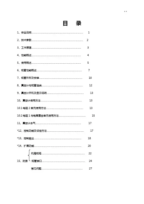
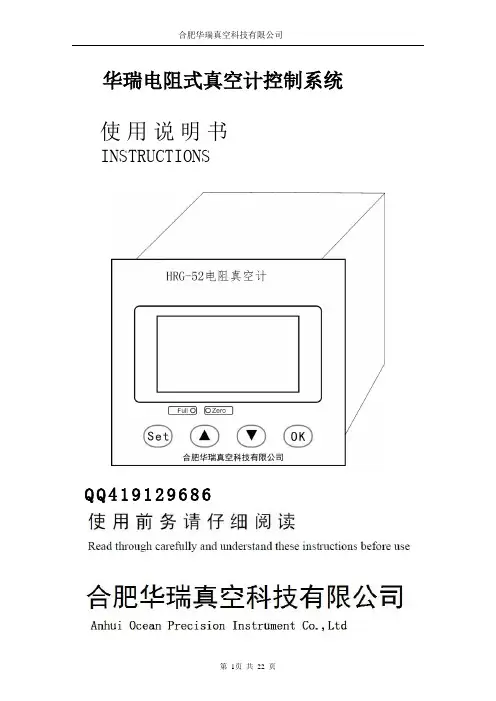
目录1、安全说明 (1)2、技术参数 (2)3、工作原理 (3)4、性能概述 (4)5、使用概述 (5)6、规管性能概述 (7)7、规管外形及安装 (10)8、真空计与规管连线 (12)9、真空计开机及显示说明 (13)10、真空计使用方法 (13)10.1电阻2单元使用方法 (13)10.2电阻1与电离复合单元使用方法 (15)11、真空计去气 (17)*12、控制功能及设定方法 (17)*13、控制输出 (18)*14、扩展功能 (20)机箱规格 (22)15、附录规管接口 (24)常见问题 (27)*号内容属选配功能说明,仅选配了此功能相应配置有效1、安全说明▲为确保该真空计的正常功能,使其具有较高的准确度、稳定性和较长的使用寿命,请根据本说明书中规定的允许值和应用条件进行操作和使用。
·操作、维护和维修该真空计时,请遵守电气设备的安全规范。
′·避免大气压下开启电离规灯丝,这将烧毁电离规灯丝。
·避免真空系统或管道有真空时,强制拆卸规管。
·避免用于“正压”的真空系统安装普通规管,应安装承受“正压”的规管。
·避免真空系统中腐蚀性气体腐蚀电阻规传感丝及电离规各电极,以延长规管寿命。
·采用适当措施防止误操作或不允许的损坏。
·如未按本说明书操作,我们将不承担任何责任;有关该真空计及其附件的保证条款也将无效。
该说明书使用符号说明:▲注意:表示必须遵循的信息,如未遵循可能会导致对人身的伤害和对该真空计的损坏。
●表示重要的附加信息和技巧或建议。
炫辰钛金保留对产品外观及设计改进和改变的权利,而无需事先通知,产品及配件以实物为准。
2、技术参数2.1 电阻单元技术参数:·配用规管型号:ZJ-52T电阻规·电阻规传感丝冷态电阻值(86.5Ω±1.7Ω)·真空度测量范围(对干燥空气或氮气)1.0×10⁵~2.5×10³可测范围。
1、复合真空计使用说明1.1 主要性能:1.1.1 本复合真空计由一个热偶计和一个宽量程的复合真空计构成.热偶采用单一的一支ZJ—54D 热偶规管进行测量。
复合真空计用一支ZJ-54D 热偶规和一支ZJ-10 电离规进行测量。
1.1.2 测量范围:热偶计:103Pa~10-1Pa复合计:103Pa~10-4Pa 。
其中电离规3.5Pa~10-4Pa。
1.1.3 本复合真空计配有RS232 接口,可与带相应接口的计算机联机。
测量数据由计算机进行管理。
1.1.4 供电:本复合真空计采用单相220V 交流供电。
电压范围:220V AC±10%;消耗功率:≤30W1.1.5 使用和储存环境:温度:5℃~35℃湿度:0~85 %严禁在高温潮湿和有腐蚀性气体的环境下工作和储存。
严禁在工作时猛烈碰撞。
1.1.6 机箱尺寸:宽×高×深=480×119×320重量:约7Kg1.1.7 出厂时规管引线均为5m。
最长建议不要长于10m。
1.1.8 RS232 接口建议采用屏蔽电缆。
屏蔽线与机壳相连,并接地。
1.1.9 电离规的启动方式:由面板上的自动、手动开关控制。
自动方式下,热偶规测量值<3.5Pa时接通,>4.0Pa 时关闭。
手动方式下,由面板上的二个ON和OFF按纽控制。
当真空度大于10Pa时,请不要打开电离规。
2.操作说明:本复合真空计是采用单片机技术的智能化仪器。
打开电源后,真空计初始化显示“HZ HZ HZ HZ”初始化完后,热偶计直接进入工作状态。
没有接入规管或规管暴露在大气中时,都是显示103Pa。
复合计:分手动和自动启动方式,在面板上,设有电离规状态指示灯。
电离规关闭或没接或故障时,ZJ-10 指示灯亮。
在手动方式下,在没有接通电离规之前,若热偶规正常,则指示热偶规测量的真空值。
接通电离规后,显示的是电离规测量的真空度。
电离规测量值≥5.0Pa 时,自动关闭电离规灯丝。
THE VERSATILE VACUUM GAUGE FOR ROUGH VACUUMDVR 2prochemical resistant, accurate, battery operatedACCESSORIESPTFE tubing KF DN 16 (1000 mm: 20686031*)DAkkS calibration with first delivery (20900214*)DAkkS recalibration (20900215*)Rubber vacuum tubing DN 6 mm (20686000*)Battery 9 V alkali-manganese (20612891*)DVR 2pro VACUUM GAUGEDVR 2pro 20682906*ORDERING INFORMATION DVR 2pro TECHNICAL DATA Upper measuring limit Lower measuring limit Measurement principle Accuracy of measurement Temperature coefficient Vacuum connection Permissible ambient temp. range storage / operation Max. media temp. for continuous operation / short times Automatic switch-off Measurement cycle Degree of protection Power supply Dimensions (L x W x H), approx. Weight, approx. DVR 2pro 1060 / 795 mbar/hPa / torr 1 / 1 mbar/hPa / torr Ceramic diaphragm (alumina), capacitive, gas indep., absolute pressure < +- 1 mbar/hPa/torr / +- 1 digit (after adjustment, constant temp.) < 0.15 mbar/hPa/0.11 torr /K Small flange KF DN 16, PTFE tubing connection 10/8 mm, hose nozzle DN 6/10 mm -10 - 60 / 10 - 40 °C 40 / 80 °C User-selectable: 1-600 min (default 5 min) or continuous operationUser-selectable: Automatic or 1 x per 3s, 1 x per 1s, 3 x per 1s IP 409 V battery 115 x 115 x 90 mm 0.4 kg VACUUBRAND GMBH + CO KG Alfred-Zippe-Straße 497877 Wertheim, Germany T +49 9342 808-5550 F +49 9342 808-5555*******************The DVR 2pro is a fully electronic, versatile vacuum gauge for use in the measuring range from at -mospheric pressure to 1 mbar. All wetted parts are made from enhanced chemical resistant mate-rials which allows for the use under very arduous laboratory conditions. The high accuracy and the large graphical display from the DVR 2 have also been carried forward for the “pro” version. One of the main enhancements is the power supply which now comprises a regular 9 V Alkaline battery. The new battery slot at the back of the gauge allows for easy replacement of the battery. A wider range of connection parts provide a great range of connection flexibility for laboratory use.ITEMS SUPPLIED Vacuum gauge complete with integrated vacuum sensor, including battery 9 V alkali-manganese, support rod, con -necting parts and manual.*Please note that from February 2018 on all VACUUBRAND catalogue numbers consist of eight digits. The previous catalogue numbers get the numerics 20… as prefix.20995581* · © 2019 VACUUBRAND GMBH + CO KG California Residents: For more information concerning California Proposition 65, please go to /calprop65。
G-5VACUUM GAUGES ELECTRONIC AND DIGITALU Reads From 5000 Down to 50 Microns U Cleanable Thermistor Sensor for Repeated Accuracy U Single Switch Operation U Low-Battery Indicator U Color-Coded LED Display Shows Vacuum RangeU Built-In Hanger/StandU Furnished with Vinyl Protective CaseOrdering Example: DVG-60,electronic vacuum gauge.Ordering Example: DVG-64, digital vacuum gauge.SPECIFICATIONS Range: 10 segments to 50 microns Connections: Standard 1⁄4" male flare fitting Power: 9V alkaline battery (included)Dimensions: 140 H x 44.5 W x 38 mm D (5.5 x 1.75 x 1.5")Case: Polycarbonate Carrying Case: Included U 12,000 to 0 MicronsU Reads Vacuum in 7 Units of MeasureU Auto Shut-Off U Built-In Hanger UCleanable SensorDVG-60 shown smaller than actual size.DVG-64 shown smaller than actual size.The OMEGA ® DVG-60 is a durable, self-contained, battery-powered electronic vacuum gauge that displays the level of vacuum on an LED color-coded readout.The 10 level color-coded LEDs display the vacuum level from 5000 down to 50 microns.The OMEGA ® DVG-64 digital vacuum gauge delivers high precision at a low price. It can accurately read vacuum from 12,000 microns down to 0, over a wide temperature range of 2 to 52°C (35 to 125°F). The vacuum can be displayed in user-selectable units.SPECIFICATIONSDisplay: Updated every 1⁄2 second; 1 micron resolution below 200 microns Sensor Type: Thermistor Connector Type: Standard 1⁄4" male flare fitting Vacuum Range: 0 to 12,000 microns (0 to 1600 Pa) with vacuum increasing/decreasing indicator when above 12,000 microns Scale: Microns, psi, inHg, mbar, Pa, torr, millitorr Operating Temperature Range: 2 to 52ºC (35 to 125ºF)Overpressure: 300 psi max (20 bar)Accuracy: ±10% (0 to 1000 microns)Power Source: 9V alkaline battery (included)Continuous Usage: Over 35 hr Auto Shut-Off: After 10 minutes when vacuum reading is above 12,000 microns Weight: 0.2 kg (6.7 oz)Dimensions: 140 H x 76 W x 32 mm D (5.5 x 3 x 1.25")。
DL-10型真空计说明书一、 概述DL-10型真空计是石英晶振真空计。
它的量程较宽,精度较高。
该真空计由规管与控制单元组成,控制单元的数码管显示压强值。
二、 技术要求1、测量范围:10-105Pa2、电源:交流220V,50Hz3、功率:7W4、几箱尺寸:200×90×160mm(宽×高×深)三、 原理DL-10型真空计是应用石英晶振的谐振阻抗与气体压强有关的特性做的真空计。
石英晶振装在铝壳中做成规管,管径为15.5mm,可通过接口插入系统。
谐振阻抗的测量电路如图1所示:图1 谐振阻抗测量电路谐振阻抗Z=V ABV AB 为晶振两端电压 I 为流过晶振的电流电流I 流过与晶振串联的电阻R ,在电阻两端的电压为V BD ∴ I =V BDZ=BDAB V V RV AB 近似等于AC 两端电压V 0,V BD 近似等于DC 两端电压V 1,由测量的V 0,V 1值及电阻值,可以计算出阻抗。
单片机将阻抗转换成压强,由数码管显示压强值。
四、 DL-10真空计的安装DL-10真空计的安装如图2所示:控制单元图2 DL-10 的安装石英晶振及振荡电路放在探头内,引线电缆通过5芯插头插入控制单元后面板的插座内,探头Φ15.5直径的管道插入真空系统。
电源电缆一头插入控制单元后面板插座,另一端插入电源插座。
电源插座应含接地线,使控制单元机箱接地。
打开电源开关,控制单元数码管显示压强值。
数码管显示3.2 E 2 表示压强值为3.2×10²Pa 。
五、 校准当环境温度变化时,应对DL-10进行校准,校准方法如下:1、 大气校准:在规管压强为大气时,用改锥按压控制单元前面板大气孔内的按键,松开后即可。
2、 零点调节:在规管压强小于1×10⁻²Pa 时,用改锥按压控制单元前面板零点孔内的按键,松开后即可。
如果真空系统达不到1×10⁻²Pa ,不可按压零点按键。