交流伺服系统中的死区效应分析与补偿
- 格式:pdf
- 大小:134.10 KB
- 文档页数:4

基于电角度相位补偿的死区在线补偿算法设计
王珂;李扬;谢成杰
【期刊名称】《电力电子技术》
【年(卷),期】2024(58)4
【摘要】伺服系统在工业自动化领域得到了广泛应用。
为解决伺服系统中由死区效应引起的相电流畸变、转矩脉动及对伺服系统响应性能的影响,提出了一种基于电角度相位补偿的死区补偿方法。
该方法补偿编码器相位延时导致的电角度相位差,通过模型预测速度控制,对多个电流环周期的电角度进行预测,并针对Sigma-Delta ADC采集中的线性相位延时进行补偿,以此判断真实电流极性。
实验结果验证了所提死区补偿方法的有效性。
【总页数】5页(P17-21)
【作者】王珂;李扬;谢成杰
【作者单位】广东工业大学
【正文语种】中文
【中图分类】TN820.3
【相关文献】
1.基于死区补偿的电液伺服PDF控制器设计
2.一种新颖的基于死区时间在线调整的SVPWM补偿算法
3.基于最小开关损耗的在线延时死区补偿算法
4.基于干扰观测器的逆变器在线死区补偿
5.基于死区补偿的电液位置伺服系统自抗扰控制
因版权原因,仅展示原文概要,查看原文内容请购买。
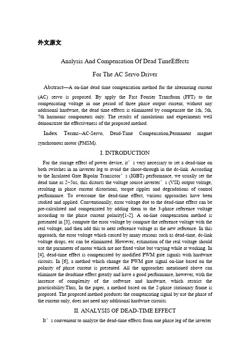
外文原文Analysis And Compensation Of Dead TimeEffectsFor The AC Servo DriverAbstract—A on-line dead time compensation method for the alternating current(AC) servo is proposed. By apply the Fast Fourier Transform (FFT) to the compensating voltage in one period of three phase output current, without any additional hardware, the dead time effects is eliminated by compensate the 1th, 5th, 7th harmonic components only. The results of simulations and experiments well demonstrate the effectiveness of the proposed method.Index Terms--AC-Servo, Dead-Time Compensation,Permanent magnetsynchronous motor (PMSM).I. INTRODUCTIONFor the storage effect of power device, it’s very necessary to set a dead-time on both switches in an inverter leg to avoid the shoot-through in the dc-link. According to the Insulated Gate Bipolar Transistor’s (IGBT) performance, we usually set the dead time as 2~5us, this distorts the voltage source inverter’s (VSI) output voltage, resulting in phase current distortions, torque ripples and degradations of control performance. To overcome the dead-time effect, various approaches have been studied and applied. Conventionally, error voltage due to the dead-time effect can be pre-calculated and compensated by adding them to the 3-phase reference voltage according to the phase current polarity[1-2]. A on-line compensation method is presented in [3], compute the error voltage by compare the reference voltage with the real voltage, and then add this to next reference voltage as the new reference. In this approach, the error voltage which caused by many reasons such as dead-time, dc-link voltage drops, etc can be eliminated. However, estimation of the real voltage should use the parameter of motor which are not fixed value but varying while at working. In [4], dead-time effect is compensated by modified PWM gate signals with hardware circuits. In [6], a method which change the PWM gate signal on-line based on the polarity of phase current is presented. All the approaches mentioned above can eliminate the deadtime effect greatly and have a good performance, however, with the increase of complexity of the software and hardware, which restrict the practicability.Thus, In the paper, a method based on the 2-phase stationary frame is proposed. The proposed method produces the compensating signal by use the phase of the current only, does not need any additional hardware circuits.II. ANALYSIS OF DEAD-TIME EFFECTIt’s convenient to analyze the dead-time effects from one phase leg of the inverterand extend the result to other phase legs. Figure.1 shows the basic configuration of onephase leg of the inverter. Define the direction of phase current flow to load is positive.Figure.1. one phase leg of the inverterA.when phase current ia is positive:When upper switch A+ turn on, lower switch A- turn off: During the dead-time and before the A+ turn on completely, the voltage of point a is clamped to –Udc/2for the D- turned on, the phase current flows through A+until A+ turned on, thus, the error time caused by deadtime effect is Td+ton, where ton is the IGBT’s turn on delay time.When upper switch A+ turn off, lower switch A- turn on: phase current flows through A+ before A+ turned off, and flows through D- when turned off. Thus, the error time caused by dead-time effect is toff, where toff is the IGBT’s turn off delay time.B. when phase current ia is negtive:When upper switch(A+)-turn on, lower switch (A-) turn off: phase current flows through A- before A- turned off, and flows through D+ when turned off. Thus, the error time caused by dead-time effect is toff. When upper switch (A+) turn off, lower switch (A-) turn on: During the dead-time and before A- turn on completely, the voltage of point a is clamped to +Udc/2 for D+ turned on. Thus, the error time caused by deadtime effect is Td+ton.Figure.2(a) shows the ideal gate signal patterns, Figure.2(b) shows the practical signal patterns considering the dead-time, Figure.2(c) shows the actual output voltage considering the dead-time and switching time for ia>0 and ia<0.Figure.2. practical switching pattern considering the dead-time and turnon/off time of switching devices. (a) ideal gate signal patterns. (b)practical signal patterns considering the dead-time. (c) actual outputvoltage considering the dead-time and switching timeThe average error voltage can be calculated from Figure.2 as in (1):d a d a U if i 0U U if i 0δ-∆〉⎧=⎨+∆〈⎩ , , (1) Where d dc s T UU T δ∆=,d on off T T t t δ=+-.According to (1) , the most obvious impact of deadtime effect is lower the output voltage, resulting in harmonics in phase current, torque ripple and speed fluctuation, especially in low speed.II. COMPENSATION OF DEAD-TIME EFFECTThe main principle of the compensation is produce a same amplitude and opposite sign voltage with the error voltage to decrease or eliminate the effect of dead-time. From (1), amplitude of the error voltage which depend on dead-time, switch period, switching time and dc-link mvoltage is fixed for off-line compensation. The key of compensation is to judge polarity of the phase current. It ’s difficult to judge the polarity of phase current accurately in the real control system, however, and the ambiguity at the zero point of phase current will deteriorate the compensation effect. Thus, in this paper, a compensation method which depend on the phase of current only in the 2-phase stationary (α /β ) frame is proposed. The error voltage depend on the polarity of phase current, so three phase current will have six different combinations of the error voltage vector. Table.I shows ,the error voltage and it ’s vector at different polarity of three phase current, where 1,22323d d K U K U =∆=∆.TABLE IERROR VOLTAGE VECTOR ACCORDING TO THE POLARITY OF THREEPHASE CURRENTFigure.3 shows the compensation voltage vector. Thecompensation voltage vector move discontinuously, andits trajectory is hexagon.Figure. 3. compensation voltage vectorThe current vector in 2-phase rotary ( d / q ) frame as shown in Figure.4. The phase of current vector can be obtained from Figure.4 as: e w dt ϕθ=+⎰Figure. 4. Phase of current vectorThe rotor flux orientated control technology be used to control PMSM in the servo system, and realize decoupling by control 0d I =, therefore, 90o θ= .Current vector with respect to error voltage vector asshown in Table.II.TABLE.II CURRENT VECTOR WITH RESPECT TO ERROR VOLTAGE VECTORBy considering the periodicity and parity of the compensation voltage vector in the α /β frame, the Fourier transform can be summarized as in (2):alfa bet 11a cos()U sin()n n n n U a n b n ϕϕ∞=∞=⎧∆=⎪⎪⎨⎪∆=⎪⎩∑∑ (2) Where n a can be calculated as in (3):0160566562222cos()24(()cos()32()cos()32()cos()34()cos()38115(sin sin sin )326226(1,2,3...)nn n d d d d d a a n d U n d U n d U n d U n d U n n n n ππππππππϕϕπϕϕπϕϕϕϕϕϕππππ∞==∆+∆+-∆+-∆∆=++=∑⎰⎰⎰⎰⎰ (3) In a similar way, n b is represented as in (4):a 0lfa sin()285(cos cos )366(1,2,3...)n d b U n d U n n n ππϕϕπππ=∆∆=-=⎰ (4) Using (3) and (4) through (2), the compensation voltage in 〈 /® frame can be obtained as:alfa beta 411(cos cos5cos 7...)57411(sin sin 5sin 7...)57d d U U U U ϕϕϕπϕϕϕπ⎧∆=∆+-+⎪⎪⎨⎪∆=∆--+⎪⎩(5) From (5), there are no zero-phase voltage such as 3-th,9-th harmonics, and higher odd harmonics have little effect to the output voltage distortion. Therefore, its sufficient to decrease the dead-time effect by compensate fundamental, 5-th and 7-th harmonics only. The block diagram of vector control containing dead-time compensation as shown in Figure.5.Figure. 5. Block diagram of FOC containing the dead-timeCompensationIV. SIMULATION OF DEAD-TIME EFFECTA preliminary simulation analysis has been performed to test the compensation validation. The simulation module of the servo system has been set up in accordance with Figure.5. Parameters of the tested motor is listed in Table.III. As operation condition, a 60r/min reference speed and a 2Nm load torque have been imposed. A 10KHz modulation frequency for the control has been imposed, while a 4.8us delay time has been considered as the system’s dead-time.TABLE.IIIPARAMETERS OF THE TESTED MOTORFigure.6 shows the simulation results of current and voltage before and after dead time compensate been used.We can see that the phase current is distorted severely due to the dead-time effects, and the distortion is remarkably reduced in the proposed scheme.(a) without dead time effect(b)with dead time effectFigure. 6. Simulation results of voltage and currentV. EXPERIMENT RESULTThe proposed compensation method is realized using a DSP-based control system of PM synchronous motor. The processor is the fixed-point DSP(TMS320LF2407A) with a clock of 40MHz. The HCPL-7840 isolation amplifier isused to measure the phase current and the dclink voltage, and the measured signals are converted to digital value by using a analog-to-digital converters (ADCs) with a resolution of 10-bits. A incremental encoder with a resolution of 2500-pulse/rev and a position processor are employed to obtain position of the rotor flux and measure the rotor speed. The resolution of speed measurement is 2r/min considering the resolution of encoder and the system sampling period. The threephase inverter is constructed by using a intelligent power module including six IGBTs, gate drives, and protection circuits. The performance of the control system with the proposed compensation scheme is compared with the no compensation scheme. Figure.7 (a) shows the experiment results of phase current without dead-time compensation. Without a compensation scheme, the dead-time causes the undesired current population in the pahse currents. However, in the proposed compensation scheme, these distortion is removed perfectly as shown in Figure.7(b).(a) without compensation(b) with compensationFigure. 7. Experiment results of a-phase currentFigure. 8 describes the steady-state speed at 60r/min. Considering the errors of measurement is 2r/min, the speed error without dead time compensation is 2r/min, and this value reduced to 0 when the proposed compensation method is applied.(a)without compensation(b) with compensationFigure. 8. Experiment results of phase speedVI. CONCLUSIONBy apply the FFT to the compensating voltage in one period of three phase output current, without any additional hardware. the dead time effects is eliminated by compensate the 1th, 5th, 7th harmonic components only. The compensation method is based on the 2-phase stationary frame. Simulation and experimental results fully confirm the validity of the compensation algorithm.VII. REFERENCES[1] Seung-Gi Jeong, Min-Ho Park. The analysis and compensation of dead-timeeffects in PWM inverters[J].Industrial Applications, IEEE Transactions, 1991, 38(2):108-114.[2] Sukegawa. T, Kamiyama. K, Mizuno. K, Matsui. T, Okuyama. T, Fully digital,vector-controlled PWM VSIfed AC drives with an inverter dead-timecompensation strategy[J]. Industry Applications, IEEE Transactions, 1991,27(3):552-559[3] Hyun-Soo Kim, Hyung-Tae Moon, Myung-Joong Youn. On-line dead-timecompensation method using disturbance observer[J]. Power Electronics , IEEE Transactions, 2003, 18(6): 1336-1345.[4] Y. Murai, T. Watanabe, H. Iwasaki. Waveform distortion and correction circuit forPWM inverters with swtiching lag-time[J]. Industrial Applications, IEEETransactions, 1987, 23(5):881-886.[5] Urasaki N, Senjyu T. A dead-time compensation strategy for permanent magnetsynchronous motor drive suppressing current distortion[C]// The 29th Annual Conference of the IEEE on Industrial Electronics Society,Virginia, USA: IEEE, 2003,2:1255-1260.[6] D. Leggate, R. J. Kerkman. Pulse-Based Dead-Time Compensator for PWM Voltage Inverters[J]. IndustrialApplications, IEEE Transactions, 1997, 44(2):191-197.中文译文关于交流伺服驱动器的死区效应的分析与补偿摘要——一个关于交流电在线死区补偿方法的建议。
SVPWM中全新的死区时间效应补偿方法杨来坡王泰宇徐鸿李千里安徽中家智锐科技有限公司摘要:文章对3相逆变的死区时间效应进行了分析,同时给出了一种全新的针对永磁同步电机驱动中死区效应的补偿方法。
该方法同时考虑了零电流钳位和寄生电容的影响,经过计算和实际验证,确实改善了死区效应的影响。
本方法理论分析的有效性及其实际效果都通过在空调直流电机驱动控制应用中得到了充分验证。
关键词:三电平逆变器;死区时间;补偿;PWMDead-time compensation in the application of SVPWM Laipo YangTaiyu WangHong XuQianli LiAnhui Cheari Zhi Rui Technology Limited CompanyAbstract: The Dead-time effect of the three phases bridge inverter is analyzed in this paper. A Dead-time compensation strategy is presented for a permanent-magnet synchronous motor drive taking zero-current damp and parasitic capacitance effects into account. It improves the Dead-time effect, with practicality and little calculation .The validity of theory analysis and this method is proved by the experiment results, the method is applied to the controlling of Air conditioner motor. Keywords: Three-level inverter;Dead time;Compensation;PWM SVPWM中全新的死区时间效应补偿方法作者:杨来坡, 王泰宇, 徐鸿, 李千里作者单位:安徽中家智锐科技有限公司本文链接:/Conference_7950587.aspx。
永磁同步电机逆变器死区补偿技术现今工业伺服驱动中多采用驱动永磁同步电动机(PMSM)的交流伺服系统,其交流驱动单元使用三相全桥电压型逆变器。
PWM调制的变频控制技术实现了对交流电机动态转矩的实时控制,大大提高了伺服系统的控制性能。
然而,对于PWM逆变器,在驱动功率管的开关信号中插入延时时间以防止直流母线直接短路,延时时间的引入将导致死区时间效应,引起逆变器输出波形的畸变和基波电压的降落,影响了伺服系统性能的进一步提高。
为补偿Td引起的电压波动,研究人员提出了各种补偿方法,大致可划分为三类。
最普遍的方法是在电流极性相同的区间内,根据缺少的脉冲列相应加上极性相反的脉冲列,以抵消其影响。
由于三相电流必有一相与另两相极性相反,一种简单的方法是对极性相反的相实行二倍的电压过补偿,使三相电压死区影响相互抵消,线电压波形为正弦形。
详细分析了死区产生的原因和影响,并根据模拟调制和数字调制分别给出了死区的硬件电路补偿方法。
文献[3]根据全桥电路的开关状态,提出了一种带死区补偿的逆变器数学模型,该模型的特点是由简单的滞环结构组成,根据此模型可由一计算公式实现死区补偿。
第二类方法是根据无效器件原理实现死区补偿的。
在任意时刻,逆变器每一桥臂两个功率器件中只有一个是有效的。
当上桥臂器件关断时,不论下桥臂器件是否导通,输出电压都是直流母线的负端电压,此时称下桥臂器件是“无效”的。
死区补偿的办法是,维持有效器件的驱动信号不变,改变无效器件的驱动信号使之满足设置死区的要求。
既然“无效”器件的通、断并不影响输出电压状态,那么也就不需要驱动信号了,只给有效器件发出驱动信号就可以了,这样也就不需要加入死区,也就没有什么死区补偿的问题了。
但该方法在电流过零点处会由于误差导致畸变,因此使用这个方法时要注意电流过零区域的处理。
一些学者进一步提出了改进方法。
在电流过零点加一滞环,在滞环时间内使用正常的开关死区保护,可减小畸变。
由于电流采样中的干扰和电流变化的复杂性,文献[5]在电流过零点附近的区域应给出两路驱动信号并加入死区及死区补偿。
全数字伺服系统中死区效应的补偿方法浙江大学 电力电子国家专业实验室 胡庆波 吕征宇关键词: 伺服系统、电压型逆变器、死区效应、谐波电流、DSP目前,在伺服控制系统中,通常采用三相电压型逆变器来驱动伺服电机。
桥式电路中为避免同一桥臂开关器件的直通现象, 必须插入死区时间。
死区时间和开关器件的非理想特性往往会造成输出电压、电流的畸变,从而造成电机转矩的脉动,影响系统工作性能。
因此,必须对电压型逆变器中的死区效应进行补偿。
文献[1-4]对三相逆变器的死区效应进行了补偿。
其中文献[1]采用平均值理论,计算出一个工作周期中的误差电压并直接补偿在参考电压上,文中忽略了开关器件的非理想特性,仅仅对死区时间造成的误差电压进行了补偿,该方法简单易行,但补偿精度较低;文献[2]在对死区时间和开关器件的非理想特性造成的死区效应进行补偿的同时,提出了一种补偿时间的离线测量方法。
该方法把开关器件的电气特性与其工作电流看成线性的关系,并且要求系统对电流有很好的控制特性;文献[3]针对空间矢量调制提出了只对其中一相电压进行补偿的方法,但没有考虑开关器件的导通压降,并且在整个逆变输出周期中,其补偿时间为一常数。
文献[4]提出了死区时间的一种离线测量方法,根据工作电流的范围预先测出补偿时间,然后分段进行补偿,该方法与前文几种补偿方法相比,可以通过电流的大小来调节补偿时间,但在一定的电流范围内补偿时间仍然是一常数。
对于逆变器的死区补偿,主要取决于两个方面,一是补偿时间的确定;二是负载电流方向的检测。
本文将对两者加以介绍。
综合上文提到的文献,其补偿时间在整个逆变输出周期皆为定值,但是在实际电路中,补偿时间往往会根据电路工作点的不同而变化。
另外,在直流侧电压较高的前提下,由开关器件的导通压降造成的畸变可以近似忽略,但在蓄电池作为直流侧输入时,其工作电压较低,此时由开关管导通压降带来的输出电压畸变较大,应加以考虑。
综合以上几点,本文提出一种死区时间的实时计算方法,即在一个逆变输出周期中,通过占空比的变化相应的调整补偿时间。