EPC1110电气转换器
- 格式:doc
- 大小:38.01 KB
- 文档页数:1

《过程控制》课程设计题目:燃油炉装置温度控制系统班级:测控二班学号:2姓名:刘朔同组人员:林波、刘登洲、刘忠昌任课教师:张虹完成时间:2014/11/20 目录一、绪论-------------------------------------------- - 1 -二、工艺流程及控制要求------------------------------- - 2 -三、对象的动态特性分析------------------------------- - 3 -四、方案设计 ---------------------------------------- - 6 -五、控制系统的工作原理------------------------------- - 9 -六、控制系统仿真 ----------------------------------- - 10 -七、结论------------------------------------------- - 12 -八、设计心得 --------------------------------------- - 14 -九、参考文献 --------------------------------------- - 15 -一、绪论过程控制是应用性和实践性较强的一门课,许多的重要概念和方法需要通过实验才能更好掌握。
通过仿真研究各种控制系统和复杂控制算法,简单快捷。
过程控制系统仿真就是以过程数学模型为基础,对过程控制系统进行实验、分析、评估和预测研究的一种技术和方法。
MATLAB的控制系统相关工具箱及Simulink的问世,给控制系统的分析和设计带来了极大地方便,已成为风行国际的、有力的控制系统计算机辅助分析、设计工具。
Simulink是一个交互式动态系统建模、仿真和分析图形环境,提供一个建立控制系统方框图,并对系统进行仿真的环境。
本文将以“燃油炉装置温度控制系统”为例,完成在Simulink基础上的仿真。

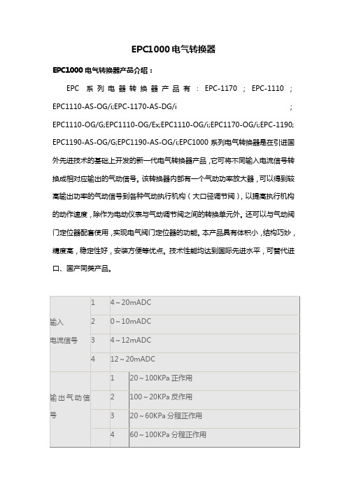
EPC1000电气转换器EPC1000电气转换器产品介绍:EPC系列电器转换器产品有:EPC-1170;EPC-1110;EPC1110-AS-OG/i;EPC-1170-AS-DG/i;EPC1110-OG/G;EPC1110-OG/Ex;EPC1110-OG/i;EPC1170-OG/i;EPC-1190; EPC1190-AS-OG/G;EPC1190-AS-OG/i;EPC1000系列电气转换器是在引进国外先进技术的基础上开发的新一代电气转换器产品,它可将不同输入电流信号转换成相对应输出的气动信号。
该转换器内部有一个气动功率放大器,可以得到较高输出功率的气动信号到各种气动执行机构(大口径调节阀),以提高执行机构的动作速度,除作为电动仪表与气动调节阀之间的转换单元外。
还可以与气动阀门定位器配套使用,实现电气阀门定位器的功能。
本产品具有体积小,结构巧妙,精度高,稳定性好,安装方便等优点。
技术性能均达到国际先进水平,可替代进口、国产同类产品。
EPC1000电气转换器技术参数:1、气源压力范围:最小值:高于输出压力上限值20kPa;最大值:700kPa。
2、气源压力对输出的影响值:≤跨度的±0.5%10kPa在中范围时。
3、线性度:≤跨度的±1%。
4、重复性:≤跨度的±0.5%。
5、回差:≤跨度的±1.0%。
6、空气流通能力最小值,在中范围175kPa气源压力时为7.6m3/h标准状态,在700kPa气源压力时为20m3/h标准状态。
7、环境条件:温度:-30℃~+60℃;湿度:<85%。
8、最大静态耗气量:中范围使用时为0.3m3/h标准状态。
9、连接尺寸:气路连接口:气源卡套式气管头φ6铜管;输出信号:卡套式气管接头φ6铜管;输出气动压力表有0-160kPa和0-250kPa两种或按输出压力选定;电气边接口:G1/2"。
10、外型尺寸:普通型及本安型:87mm×160mm×107mm;隔爆型:97mm×186mm×202mm11、重量:普通型及本安型0.9kg,隔爆型2.35kg。

10/100 Fiber to Ethernet Media Converter Multi Mode SC 2 kmProduct ID: MCM110SC2The MCM110SC2 10/100 Multi Mode Fiber Ethernet Media Converter SC 2 km creates an economical, cost-effective Ethernet-fiber link, transparently converting to/from 10Base-T or 100Base-Tx Ethernet signals and 100Base-Fx optical signals to extend an Ethernet network connection over an SC terminated multimode fiber backbone.The converter supports a maximum multimode fiber optic cable distance of 2 kilometers (1.2 miles), providing a simple solution for connecting 10Base-T/100Base-Tx Ethernet networks to remote locations using SC-terminated multimode fiber, while delivering solid network performance and scalability.This versatile Ethernet to Fiber converter is compatible with most 3COM™, Cisco™, Lucent™ and Nortel™networks and fully complies with applicable IEEE 802.3 standards.Backed by a 2-year warranty and free lifetime technical support.Certifications, Reports and Compatibility Applications•Extend your Ethernet connection up to 2km away using fiber optics•Designed for large, high speed work groups that require expansion of fast Ethernet Networks•Connect via fiber optics two or more buildings on the same campus•Connect remote sub-networks to larger fiber opticnetworks/backbonesFeatures•Supports a maximum multi mode fiber optic cable distance of 2 km•Compatible with most 3COM™, Cisco™, Lucent™ and Nortel™networks•Compact design•Supports transparent Q-in-Q double tagged frames•Supports Link Fault Pass through (LFP)•Supports IEEE 802.1q Tag VLAN pass thru•Supports flow control (Pause)•Provides switch configuration of half/full duplex transfer mode for FX port•LED Indicators for simple Ethernet/Fiber network link monitoring•Forward 9K jumbo packets in converter mode•Auto negotiation or Force 10/100 Mbps and MDI/MDI-X (Crossover for TX port)•Auto detects half/full duplex transfer mode from the TX port •Manual controls for UTP mode, speed, Full and Half Duplex, and LFP (Link Fault pass-through) on/off•Simple installationWarranty 2 YearsHardware Industry Standards IEEE 802.3 10BASE-TIEEE 802.3u 100BASE-FXIEEE 802.3u 100BASE-TXPoE NoWDM NoPerformance Fiber Operating Mode Half/Full-DuplexMax Transfer Distance 2 km (1.2 mi)Maximum Data Transfer Rate10/100MbpsMTBF65,000 HoursType Multi ModeWavelength1310nmConnector(s)Local Unit Connectors 1 - RJ-45 FemaleRemote Unit Connectors 1 - Fiber Optic SC Duplex FemaleIndicators LED Indicators 1 - Ethernet Link & Activity (ON - Ethernet Link OK, Blinking- Activity on Ethernet Link)1 - FEF [Far End Fault](On - Fault Detected, Off - No Fault1 - Fiber Link & Activity (On - Fiber Link OK, Blinking -Activity on Fiber Link)1 - Full ( Full duplex / Half duplex)1 - Power1 - Speed (Off - 10Mbps, On - 100 Mbps)Power Center Tip Polarity PositiveInput Voltage100 - 240 ACOutput Current0.2AOutput Voltage12 DCPlug Type MPower Consumption (In Watts) 2.4Power Source AC Adapter IncludedEnvironmental Humidity10~90% RHOperating Temperature0°C to 50°C (32°F to 122°F)Storage Temperature-10°C to 70°C (14°F to 158°F)PhysicalColor Black CharacteristicsEnclosure Type PlasticProduct Height0.8 in [2 cm]Product Length 3.7 in [95 mm]Product Width 3 in [75 mm]Weight of Product 3 oz [84 g]Package Height 2.5 in [63 mm] PackagingInformationPackage Length 6.9 in [17.5 cm]Package Width 5.7 in [14.5 cm]Shipping (Package) Weight9.5 oz [269 g] What's in the Box Included in Package 1 - Media Converter1 - Power Adapter1 - User's Manual Product appearance and specifications are subject to change without notice.。
Installation InstructionsNOTE: Read the entire instruction manual before starting the installation.SAFETY CONSIDERATIONInstalling and servicing heating equipment can be hazardous due to gas and electrical components. Only trained and qualified personnel should install, repair, or service heating equipment.Untrained personnel can perform basic maintenance functions such as cleaning and replacing air filters. Trained service personnel must perform all other operations. When working on heating equipment, observe precautions in the literature, on tags, and on labels attached to or shipped with the unit, and other safety precautions that may apply.Follow all safety codes. In the United States, follow all safety codes including the current edition of the National Fuel Gas Code (NFGC) NFPA No. 54/ANSI Z223.1. In Canada, refer to the current edition of the National Standard of Canada, Natural Gas and Propane Installation Codes (NSCNGPIC), CAN/CSA−B149.1 and .2. Wear safety glasses and work gloves. Have a fire extinguisher available during start−up, adjustment steps, and service calls.Recognize safety information. This is the safety−alert symbol . When you see this symbol on the furnace and in instructions or manuals, be alert to the potential for personal injury. Understand the signal words DANGER, WARNING, CAUTION and NOTE. The words DANGER, WARNING, and CAUTION are used with the safety alert symbol. DANGER identifies the most serious hazards which will result in severe personal injury or death.WARNING signifies a hazard which could result in personal injury or death. CAUTION is used to identify unsafe practices which may result in minor personal injury or product and property damage. NOTE is used to highlight suggestions which will result in enhanced installation, reliability, or operation.INTRODUCTION1This instruction covers the installation of gas conversion kit to convert the 59SC5, 59SP5, 915S, 925S and PG95S 26,000 BTUH low capacity furnaces from Propane gas usage to natural gas usage. DESCRIPTION AND USAGESee Table 1 for kit contents. This kit is designed for use in the furnaces listed in Table 2. To accommodate many different furnace models, more parts are shipped in kit than will be needed to complete conversion. When installation is complete, discard extra parts.INSTALLATION1.Set room thermostat to lowest setting or “OFF”2.Disconnect power at external disconnect, fuse orcircuit breaker.3.Turn off gas at external shut−off or gas meter.4.Remove outer doors and set aside.5.Turn electric switch on gas valve to OFF.MANIFOLD/ORIFICE/BURNER REMOVAL1.Disconnect the gas pipe from gas valve and removepipe from the furnace casing. See Figure 1. NOTE: Use a back−up wrench on the gas valve to prevent the valve from rotating on the manifold or damaging the mounting to the burner box. See Figure 2 and Figure 3.2.Disconnect the connector harness from gas valve.Disconnect wires from Hot Surface Igniter (HSI) andFlame Sensor. Disconnect the two wires from theLow Gas Pressure Switch (LGPS) located on thegas valve.3.Support the manifold and remove the 4 screws thatsecure the manifold assembly to the burner box andset aside.4.Note the location of the green/yellow wire groundwire for re−assembly later. See Figure 2.REPRESENTATIVE DRAWING ONLY, SOME MODELS MAY VARY IN APPEARANCE.A170154Figure 1 −Representative Furnace Drawing235.Slide one −piece burner assembly out of slots on sides of burner box.6.Remove the flame sensor from the burner assembly.See Figure 3.7.Remove the orifices from the manifold and discard.Gas valve must be installed onmanifold with minimum engagement of 6threads Cross threading is not˚+ or -2˚C L Gas valve is parallel to manifold within + or - 3˚A11407Figure 2 − Manifold AssemblyA11403Figure 3 − Burner AssemblyORIFICE SELECTION/DERATEA96249Figure 4 − Burner OrificeDetermine natural gas orifice size and manifold pressure for correct input at installed altitude by using Table 3.1.Obtain yearly heat −value average (at installed altitude) for local gas supply.2.Obtain yearly specific −gravity average for local gas supply.3.Find installation altitude in Table 3.NOTE : For Canada altitudes of 2000 to 4500 ft., use U.S.A. Altitudes of 2001 to 3000 ft. In Table 3.4.Find closest natural gas heat value and specific gravity in Table 3.5.Follow heat −value line and specific −gravity line to point of intersection to find orifice size and manifold pressure settings.Furnace gas input rate on furnace rating plate is for installations at altitudes up to 2000 ft. (610 M).In the U.S.A .; the input rating for altitudes above 2000 ft.(610 M) must be reduced by 2 percent for each 1000 ft.(305 M) above sea level.In Canada , the input rating must be derated by 5 percent for altitudes of 2000 ft. to 4500 ft. (610 M to 1372 M) above sea level.The Conversion Kit Rating Plate accounts for high altitude derate.INSTALL ORIFICES1.Install main burner orifices. DO NOT use Teflon tape.Finger −tighten orifices at least one full turn to prevent cross −threading, then tighten with wrench.2.There are additional size orifices for different heat content gases. Discard extra orifices.NOTE : DO NOT reinstall the manifold at this time.REMOVE MIXER SCREWS FROM THE BURNERSNOTE : Each burner contains a mixer screw that must be removed. Refer to Figure 5 for the mixer screw location.1.Remove the mixer screws from the burners.NOTE : It is not necessary to plug the hole in the burnerwhen the mixer screws are removed.A11501Figure 5 − Mixer Screw LocationREINSTALL BURNER ASSEMBLY To reinstall burner assembly:1.Attach flame sensor to burner assembly.2.Insert one-piece burner in slot on sides of burner boxand slide burner back in place.3.Reattach HSI wires to HSI.4.Verify igniter to burner alignment. See Figure 6 &Figure 7.(64.4)A11405 Figure 6 −Igniter Position − Back Viewin., +0.8 -1.5)in., +1/32 -3/64-in.A12932 Figure 7 −Igniter Position − Side ViewCONVERT GAS VALVE NOTE: The green labeled Low−Capacity single−stagevalve DOES NOT need to have the regulator spring replaced in the gas valve. The regulator in the gas valvemust be pre−adjusted to convert from propane to naturalgas applications. An identical regulator spring is included in the kit to be used in the event the factory spring is unnecessarily removed and misplaced during the propane conversion. The regulator spring is red in color to distinguish it from other regulator springs.1.Refer to Figure 8.2.Be sure gas and electrical supplies to furnace areoff.3.Remove cap that conceals the adjustment screw forthe gas−valve regulator. (See Figure 8.)4.Turn the regulator adjustment screw one (1) full turnout. This will decrease the manifold pressure closerto the natural gas set point.5.DO NOT install the brass regulator seal cap at thistime.6.If the red regulator spring is removed, install thespring and the adjustment screw.7.Turn the adjusting screw clockwise (in) 10.5 fullturns. This will increase the manifold pressure closerto the natural gas set point. (See Figure 8.)8.DO NOT install regulator seal cap at this time.Regulator AdjustmentScrewA150593 Single−Stage Gas Valve without Tower Pressure Ports45A170140PRESSURE TAPUNDER CAP)MANIFOLD PRESSURE TAP SET SCREW: 3/32” HEX HEADRepresentative drawing only, some models may vary in appearance.Figure 8 − Single −Stage Gas Valve with TowerPressure PortsREMOVE LOW GAS PRESSURE SWITCHNOTE : There are two ways that the Low Gas Pressure Switch (LGPS) could have been installed during the original natural to Propane gas conversion.All 14 3/16-in (360 mm) Casings or Vent Passed Between Inducer Assembly and Burner AssemblyIf the vent pipe passes between the inducer and burner assembly, or the furnace is a 14 3/16-in. (360 mm) wide casing. The switch may be installed as shown in Figure 9.1.Remove low gas pressure switch, brass street 90_elbow, brass Hex nipple, brass tee and black iron street 90_ elbow from the gas valve inlet pressure tap. (See Figure 9.)NOTE : Use pipe dope approved for use with Propane gas.DO NOT use Teflon tape.2.Apply pipe dope sparingly to the 1/8−in. NPT pipe plug (provided in kit) and install in the 1/8−in tapped inlet −pressure tap opening in the gas valve. DO NOT over −tighten. Check for gas leaks after gas supplyhas been turned on.A170141Figure 9 − Low Gas Pressure Switch RemovalCasings Wider Than 14 3/16-in. (360 mm) / Vent Does Not Pass Between Inducer and Burner AssemblyIf the vent pipe does not pass between the inducer and burner assembly, or the furnace is wider than a 14 3/16-in.(360 mm) wide casing. The switch may be installed as shown in Figure 10.1.Remove Low Gas Pressure Switch, brass street tee,brass nipple and brass street 90_ elbow from the gas valve inlet pressure tap. See Figure 10.NOTE : Use pipe dope approved for use with Propane gas.DO NOT use Teflon tape.2.Apply pipe dope sparingly to the 1/8−in. NPT pipe plug (provided in kit) and install in the 1/8−in tapped inlet −pressure tap opening in the gas valve. DO NOT over −tighten. Check for gas leaks after gas supplyhas been turned on.L13F012Figure 10 − Alternate Low Gas Pressure SwitchRemovalINSTALL MANIFOLD1.Align the orifices in the manifold assembly with thesupport rings on the end of the burner.2.Insert the orifices in the support rings of the burners.Manifold mounting tabs should fit flush against theburner box.NOTE: If manifold does not fit flush against the burner box, the burners are not fully seated forward. Remove the manifold and check burner positioning in the burner box assembly.3.Attach the green/yellow wire and ground terminal toone of the manifold mounting screws. See Figure 2.4.Install the remaining manifold mounting screws.5.Connect the wires to the flame sensor and hotsurface igniter.6.Connect the connector harness to gas valve.7.Rewire unit low pressure switch (LPS) as follows:a.Trace one of the orange wires previouslydisconnected from the LGPS back to the NOterminals of the LPS.b.Trace the other orange wire previouslydisconnected from the LGPS back to its spliceconnection with the yellow wire of the furnacewire harness. Disconnect and discard this orangewire and the splice connection.c.Connect the yellow wire of the furnace wireharness (see “b” above) to the NO terminal of theLPS.d.Refer to the furnace wiring diagram to ensureproper location of wires.NOTE: Use only Propane-resistant pipe dope. DO NOT use Teflon tape.8.Insert the gas pipe through the grommet in thecasing. Apply a thin layer of pipe dope to the threadsof the pipe and thread the pipe by into the gas valve. NOTE: Use a back-up wrench on the gas valve to prevent the valve from rotating on the manifold or damaging the mounting to the burner box.9. With a back-up wrench on the inlet boss of the gasvalve, finish tightening the gas pipe to the gas valve.10.Turn gas on at electric switch on gas valve. CHECK INLET GAS PRESSURENOTE: This kit is to be used only when inlet gas pressure is between 4.5−in. W.C. and 13.6−in. W.C.1.On some models, remove 1/8-in. (3 mm) pipe plugfrom pressure tap on the inlet end of gas valve andinsert pressure tap. Or, on some models, loosen setscrew on inlet tower pressure tap no more than onefull turn with the 3/32−in. hex wrench.2.Verify manometer is connected to inlet pressure tapon gas valve. (See Figure 8.)3.Turn on furnace power supply.4.Turn gas supply manual shutoff valve to ON position.5.Turn furnace gas valve switch to ON position.6.Jumper R−W thermostat connections on control.7.When main burners ignite, confirm inlet gas pressureis between 4.5−in. W.C. and 13.6−in. W.C.8.Remove jumper across R−W thermostat connectionsto terminate call for heat.9.Turn furnace gas valve switch to OFF position.10.Turn gas supply manual shutoff valve to OFFposition.11.Turn off furnace power supply.12.Remove manometer and on some models removepressure tap fitting.13.On some models, apply pipe dope sparingly to the1/8−in. (3 mm) NPT pipe plug and install in the1/8−in. (3 mm) tapped inlet−pressure tap opening inthe gas valve. Or, on some models, tighten set screwon inlet tower pressure tap with a 3/32−in. hexwrench. (See Figure 8.)CHECK FURNACE AND MAKEADJUSTMENTS61.Be sure main gas and electric supplies to furnaceare off.2.On some models, remove 1/8-in. (3 mm) NPT pipeplug from manifold pressure tap on outlet end of gasvalve. Or, on some models, loosen set screw onmanifold tower pressure tap no more than one fullturn with a 3/32−in. hex wrench.3.Attach manometer to manifold pressure tap on gasvalve. (see Figure 8)4.Turn gas supply manual shutoff valve to ON position.5.Turn furnace gas valve switch to ON position.6.Check all threaded pipe connections for gas leaks.7.Turn on furnace power supply.GAS INPUT RATE INFORMATION See furnace rating plate on blower door for input rate. The input rate for natural gas is determined by manifold pressure and orifice size.Determine natural gas orifice size and manifold pressure for correct input at installed altitude by using Table 3.1.Obtain yearly heat−value average (at installedaltitude) for local gas supply.2.Obtain yearly specific−gravity average for local gassupply.3.Find installation altitude in Table 3.NOTE: For Canada altitudes of 2000 to 4500 ft., use U.S.A. Altitudes of 2001 to 3000 ft. in Table 3.4.Find closest natural gas heat value and specificgravity in Table 3.5.Follow heat−value line and specific−gravity line topoint of intersection to find orifice size and manifoldpressure setting.Furnace gas input rate on rating plate is for installations at altitudes up to 2000 ft. (610 M).In the U.S.A.; the input rating for altitudes above 2000 ft. (610M) must be reduced by 2 percent for each 1000 ft. (305 M) above sea level.In Canada; the input rating must be derated by 5 percent for altitudes of 2000 ft. (610 M) to 4500 ft. (1372 M) above sea level.The Conversion Kit Rating Plate accounts for high altitude derate.SET GAS INPUT RATE6.Jumper R and W thermostat connections to call forheat. (See Figure 12.)7.Check manifold orifices for gas leaks when mainburners ignite.8.Adjust gas manifold pressure. Refer to Table 3.9.Remove cap that conceals the gas valve regulatoradjustment screw.10.Turn adjusting screw counterclockwise (out) todecrease manifold pressure or clockwise (in) toincrease manifold pressure.11.Replace gas valve regulator seal cap.12.Verify manifold pressure is correct. Refer to Table 3.NOTE: Gas valve regulator seal cap MUST be in place when checking input rate. When correct input is obtained, main burner flame should be clear blue, almost transparent (See Figure 11). Be sure regulator seal cap is in place when finished.13.Remove jumper across R and W thermostatconnections to terminate call for heat.14.Turn furnace gas valve control switch or control knobto OFF position.15.Turn off furnace power supply.16.Remove manometer and on some models removepressure tap fitting.17.On some models, apply pipe dope sparingly to endof 1/8−in. (3 mm) pipe plug and install in the manifoldpressure tap opening. Or, on some models, tightenset screw on manifold tower pressure tap with a3/32−in. hex wrench. See Figure 8.18.Turn furnace gas−valve switch to ON position.19.Turn on furnace power supply.20.Set room thermostat to call for heat.21.Check pressure tap plug for gas leaks when mainburners ignite.22.Check for correct burner flame.23.After making the required manifold pressureadjustments, check and adjust the furnacetemperature rise per the furnace installationinstructions.78Table 3 – Orifice Size and Manifold Pressure Table26,000 BTUH ONLYAVG. GAS HEAT VALUE AT ALTITUDE Orifice Manifold Orifice Manifold Orifice Manifold Orifice Manifold (Btu/cu ft)No.Pressure No.Pressure No.Pressure No.Pressure 90044 1.843 1.743 1.743 1.8092544 1.744 1.843 1.643 1.7(0)95044 1.644 1.744 1.844 1.897544 1.644 1.644 1.744 1.7to 100044 1.544 1.544 1.644 1.6102544 1.444 1.544 1.544 1.62000105044 1.344 1.444 1.444 1.5(610)107544 1.344 1.344 1.444 1.4110044 1.244 1.344 1.344 1.4U.S.A.80043 1.743 1.843 1.842 1.62001 (611)82543 1.643 1.743 1.743 1.8to 85044 1.844 1.843 1.643 1.73000 (914)87544 1.744 1.744 1.844 1.890044 1.644 1.644 1.744 1.7Canada 92544 1.544 1.544 1.644 1.62001 (611)95044 1.444 1.544 1.544 1.6to 97544 1.344 1.444 1.444 1.54500 (1372)100044 1.344 1.344 1.444 1.477543 1.743 1.843 1.842 1.580044 1.843 1.743 1.743 1.8300182544 1.744 1.844 1.843 1.7(915)85044 1.644 1.744 1.744 1.887544 1.544 1.644 1.644 1.790044 1.444 1.544 1.544 1.6400092544 1.444 1.444 1.544 1.5(1219)95044 1.344 1.344 1.444 1.475043 1.743 1.743 1.843 1.877544 1.843 1.643 1.743 1.7400180044 1.744 1.744 1.843 1.6(1220)82544 1.644 1.644 1.744 1.885044 1.544 1.544 1.644 1.7to 87544 1.444 1.544 1.544 1.6500090044 1.344 1.444 1.444 1.5(1524)92544 1.344 1.344 1.444 1.472543 1.743 1.743 1.843 1.8500175044 1.844 1.843 1.743 1.7(1525)77544 1.744 1.744 1.844 1.880044 1.644 1.644 1.744 1.782544 1.544 1.544 1.644 1.685044 1.444 1.444 1.544 1.5600087544 1.344 1.344 1.444 1.4(1829)90044 1.244 1.344 1.344 1.467543 1.843 1.842 1.542 1.6600170043 1.643 1.743 1.743 1.8(1830)72544 1.744 1.843 1.643 1.775044 1.644 1.744 1.744 1.877544 1.544 1.644 1.644 1.7700080044 1.444 1.544 1.544 1.6(2133)82544 1.344 1.444 1.444 1.5850441.3441.3441.4441.4* Orifice numbers shown in BOLD are factory-installed.U .S .A . O n l y U .S .A . O n l y to U .S .A . O n l y toORIFICE SIZE* AND MANIFOLD PRESSURE (IN WC) FOR GAS INPUT RATE(TABULATED DATA BASED ON 13,000 BTUH PER BURNER, DERATED 2%/1000 FT (305M) ABOVE SEA LEVELALTITUDE RANGE U .S .A . a n d C a n a d aU .S .A . a n d C a n a d aU .S .A . O n l yft (m)SPECIFIC GRAVITY OF NATURAL GAS0.580.600.620.64to A1505719Table 3 − Orifice Size and Manifold Pressure (in. w.c.) for Gas Input Rate (continued)26,000 BTUH ONLY65043 1.743 1.842 1.542 1.6700167544 1.843 1.743 1.743 1.8(2134)70044 1.744 1.844 1.843 1.772544 1.644 1.744 1.744 1.875044 1.544 1.544 1.644 1.6800077544 1.444 1.444 1.544 1.5(2438)80044 1.344 1.444 1.444 1.482544 1.244 1.344 1.344 1.462543 1.743 1.843 1.842 1.6800165044 1.843 1.743 1.743 1.8(2439)67544 1.744 1.844 1.843 1.670044 1.644 1.644 1.744 1.772544 1.544 1.544 1.644 1.6900075044 1.444 1.444 1.544 1.5(2743)77544 1.344 1.344 1.444 1.4900160043 1.743 1.843 1.842 1.6(2744)62544 1.843 1.643 1.743 1.765044 1.744 1.744 1.844 1.867544 1.644 1.644 1.744 1.71000070044 1.444 1.544 1.544 1.6(3048)725441.3441.4441.4441.5* Orifice numbers shown in BOLD are factory-installed.U .S .A . O n l yto U .S .A . O n l yto U .S .A . O n l y to ORIFICE SIZE* AND MANIFOLD PRESSURE (IN WC) FOR GAS INPUT RATE(TABULATED DATA BASED ON 13,000 BTUH PER BURNER, DERATED 2%/1000 FT (305M) ABOVE SEA LEVELCHECKOUT1.Observe unit operation through two (2) complete heating cycles.2.See Sequence of Operation in furnace Installation,Start −Up, and Operating Instructions.3.Set room thermostat to desired temperature.Figure 11 − Burner FlameA11391Figure 12 − Single −Stage Furnace ControlLABEL APPLICATION1.Fill in Conversion Responsibility Label 342015−205and apply to blower door of furnace as shown. Date,name, and address of organization making this conversion are required. See Figure 13.2.Attach Conversion Rating Plate Label 342015−201to outer door of furnace. See Figure 13.3.Apply Gas Control Conversion Label to gas valve:For single −stage gas valve apply label 342015−202to gas valve. (DO NOT use 342015−203, which is similar) Check for correct normal operating sequence of the ignition system as described in furnace Installation, Start −Up, and Operating Instructions.4.Replace control access door, blower door and outer door of furnace.10A150645Figure 13 − Conversion Kit LabelsCopyright 2017 CAC / BDP D 7310 W. Morris St. D Indianapolis, IN 46231Manufacturer reserves the right to change, at any time, specifications and designs without notice and without obligations.Catalog No: AG-KGAPN4601-02Replaces: AG −KGAPN46011SP −01Edition Date: 09/17。
EPC1110电气转换器性能介绍:
EPC1110电气转换器使用方式,正反作用可方便调换校整,正反作用不必注明,常规型以正作用提凸轮特性(一般调节阀凸轮特性为线性,不必注明,等百分比和非线需特注)。
执行机构行用户需100mm或超过100mm行程调节阀配套时,订货需特殊注明)附件:(常规的附件可随产品提供)非常规附件安装联板,运动联板组件是否要,要请提供执行机构型号,气管外径。
EPC1110电气转换器安装尺寸:
DN L H D D1 D2 b f n-d
10 115 153 90 60 41 14 3 4-φ14
15 115 153 95 65 46 14 3 4-φ14
20 115 153 105 75 56 16 3 4-φ14
25 125 153 115 85 65 16 3 4-φ14
32 150 176 140 100 76 18 3 4-φ18
40 165 176 150 110 84 18 3 4-φ18
50 190 192 165 125 99 20 3 4-φ18
EPC1110电气转换器产品特点:
EPC1110电气转换器是一种新型结构的电气转换单元,它可将不同输入电流信号转换成相对应输出的气动信号。
该转换器内部有一个气动功率放大器,可以得到较高输出功率的气动信号到各种气动执行机构,
以提高执行机构的动作速度。
EPC1110电气转换器的用途:
按阀门定位器输出和输入信号的增益符号分为正作用阀门定位器和反作用阀门定位器。
正作用阀门定位器的输入信号增加时,输出信号也增加,因此,增益为正。
反作用阀门定位器的输入信号增加时,输出信号
减小,因此,增益为负。