费希尔I2P-100型电气转换器
- 格式:pdf
- 大小:118.43 KB
- 文档页数:8

MUP100/150系列信号转换器特点:• 专为电位计式位移传感器和角位移传感器配置的信号调节装置• 有电隔离型可供选择(带DC/DC 变换器)• 标准输出信号: 0 ... 10 V± 10 V0 ... 20 mA4 ... 20 mA± 20 mA• 极佳的线性度• 极低的温度漂移(典型温漂值为20 ppm/K )• 标准导轨固定安装,符合DIN EN 50022标准该信号转换器提供一个非常稳定的恒定电压给位移传感器,传感器滑刷上的信号来自无负载的高阻抗输入端,此信号能被转换成与所测位移成正比例关系的标准信号输出。
信号转换器所具有的优良的线性度、极低的温漂以及与传感器相匹配的信号处理方式等保证了位移传感器在使用过程中具有杰出表现;即便在信号传递距离很远的工况下,也能保证传递的可靠性和抗干扰。
用户可以分别对转换器输出信号的零点和信号输出范围在较大范围内进行调整;即便实际测量长度小于传感器的最大可测长度,也可将转换器的机械参数单位尺寸见尺寸图防护等级IP 50 / IP 00 (终端保护)螺纹接线端子 1.5 (AWG 14) mm 2安装固定导轨35 (DIN EN 50022)mm 重量约110g 电气参数工作电压18 ... 30VDC 输入阻抗> 10M Ω接反电压保护集成式功耗70mA 提供给位移传感器的高稳定且带短路保护的内部参考电压10VDC 位移传感器的允许连接阻抗≥ 700Ω调节范围 零位增益-30 ... +20 0.65 ... 2%线性度0.01 (通常)%温度系数*20 (通常)ppm/K 工作温度范围-25 ... +70℃注: 温度系数将影响输出电流和输出电压。
若为输出电流信号,则电压要通过连接负载阻抗获取,故负载阻抗的温度系数也必须加以考虑。
输出信号转换成标准值输出。
该产品电路被封装在一个绝缘塑料机壳内。
此机壳可固定在标准的DIN EN 50022安装轨道上。

PROFIBUS通信转换器IFP-100使用说明书警告在进行配线或检查作业前,应先断开仪表电源。
在未断电的情况下作业,将可能因电击导致人身重大伤害事故!IFP-1001. 简介1.1 IFP-100简介------------------------------------------------------------------------------- 3 1.2 系统配置----------------------------------------------------------------------------------- 32. 型号2.1 型号----------------------------------------------------------------------------------------- 3 2.2 型号铭牌的表示方法-------------------------------------------------------------------- 33.各部位名称和功能--------------------------------------------------------------- 34. 设定------------------------------------------------------------------------------- 45. 安装5.1 场所选择----------------------------------------------------------------------------------- 5 5.2 外形尺寸图-------------------------------------------------------------------------------- 5 5.3 圆形插座安装----------------------------------------------------------------------------- 66. 导线连接6.1 接线端排列-------------------------------------------------------------------------------- 7 6.2 导线连接实例----------------------------------------------------------------------------- 77. 通信数据7.1数据形式------------------------------------------------------------------------------------ 9 7.2数据结构------------------------------------------------------------------------------------ 9 7.3数据设定过程-------------------------------------------------------------------------------- 12 7.4读数据过程-------------------------------------------------------------------------------- 12 7.5数据传送------------------------------------------------------------------------------------- 128. 规格--------------------------------------------------------------------------------- 139. 故障排除--------------------------------------------------------------------------141. 简介1.1 IFP-100简介IFP-100 是一种通信转换器,用来连接PROFIBUS主机单元(SIEMENS PLC,等),作为PROFIBUS-DP从机单元,进行数据交换。

1981Line Impedance Stabilization Networks (LISN) are specialized low pasfrom power lines. Fischer Custom Communications, Inc. has developedcompliance testing requirements and custom customer needs. FCC LISwith CISPR, VDE, IEC, DO-160 and Mil-Std. 461/462 Rev D.Fischer Custom Communications, Inc. develops and manufactures Lincovering the frequency range from 6 kHz to 1,000 MHz.A prime example of this type of LISN is the 50?50 µH configuration defined in Cthe transfer impedance for this LISN are shown below. The CISPR 16-1 limit linThe model FCC-LISN-50-25-2 is produced in accord with the required schem requirements. The impedance versus frequency curve of this LISN is superim configuration. The 50Ω50Ω µH configuration is often used for Mil Std conduct specific details refer to Mil Std 461/462 D.In addition to this LISN there are 50Ωversions used to test both to lower and require conducted emission measurements on electronic devices from 9 kHz a 250 µH inductor and additional resistor and capacitance networks are added defines this LISN as 50Ω50Ω µH + 5 W. This type of LISN is often used when In contrast the aerospace, automotive and aircraft industries require conducte MHz. To achieve the higher bandwidth a 5 µH inductor is used.Voltage and current rating of the LISN are the second characteristic. It is impo to operate as intended. Fischer Custom Communications, Inc. offers LISN's line and current ratings from 16 A to 200 A..The third parameter is the number of power conductors or lines. EMI specifica leads to be tested for conducted emissions. Any neutral or ground wires not c tested. DC and AC single phase power circuits must be tested using LISN mo power network requires tests to be conducted with a LISN's containing three p system must be tested with LISN modules having four lines. To maximize flex LISN modules containing one, two and four power conductors.Fischer Custom Communications Inc. offers over twenty connectors. The ke in compliance with IEC 1010, not cause the impedance of the LISN to vary an Fischer Custom Communications Inc. LISN's come with transfer impedance We strongly recommend that IEC 320 or NEMA connectors be used to elimina All of Fischer Custom Communications, Inc. LISN's are easily mounted to th Additional grounding is available.LISN Selection Guide CodesConnector Code01020304050607080910111213 Multi-Contact Satety SocketSuperior Plug and Jack Safety SocketIEC 320, 10 A / 16A PowerIEC 320, 10 A / 16A PowerFrench /Belgium 16 A PowerBS 1363 13 A British PowerCEE 7/7 16A Schuko Berman PowerNema 5-15, 15 A US PowerNema 5-15, 15 A US PowerIEC 309, 16 A 3-Wire PowerIEC 309, 16 A 3-Wire PowerHubbel 330P6W, 30 A 3-Wire US PowerHubbel 330P6W, 30 A 3-Wire US PowerT010203040506070809CFFMMDSTV141516171819 Hubbel 330P6W, 30 A 3-Wire US Power Hubbel 330P6W, 30 A 3-Wire US Power IEC 309, 32 A 5-Wire PowerIEC 309, 32 A 5-Wire PowerIEC 309, 32 A 5-Wire PowerLC Coaxial for TempestFiltered LISN's remotely switched LISN's and low profile LISN's for under turn GHz are now available.Remotely switched LISN's may be controlled by the remote control or via a pe output 0-5 volt DC logic levels. The remote control and 50 foot cable are supp remote connector is filtered to prevent external noise from entering the LISN e LISN Selection GuideModel MaximumFrequencyNetworkInductanceMaximumCurrent*StandardMaximumVoltageFCC-LISN-5-50-10.1-100MHz50Ω/5µH50 A240FCC-LISN-5-50-1-DO-1600.1-400MHz50Ω/5µH50 A240FCC-LISN-5-50-1-T 0.1-1,000MHz50Ω/5µH50 A240FCC-LISN-5-100-10.1-65 MHz50Ω/5µH100 A240FCC-LISN-50-50-10.15-100MHz50Ω/50µH50 A240FCC-LISN-50-100-10.15-30MHz50Ω/50µH100 A240FCC-LISN-50-200-10.15-30MHz50Ω/50µH200 A240FCC-LISN-57-50-10.01-10MHz50Ω/57µH50 A240FCC-LISN-50-25-20.15-100MHz50Ω/50µH25 A240FCC-LISN-50-32-20.15-100MHz50Ω/50µH32 A240FCC-LISN-50-50-20.15-100MHz50Ω/50µH50 A240FCC-LISN-50-32-40.15-100MHz50Ω/50µH32 A240FCC-LISN-50-50-40.15-100MHz50Ω/50µH50 A240FCC-LISN-50-100-40.15-30MHz50Ω/50µH100 A240FCC-LISN-50/250-25-20.009-100MHz50Ω/50µH +5Ω50/250 µH25 A240FCC-LISN-50/250-32-20.009-100MHz50Ω/50µH +5Ω50/250 µH32 A240FCC-LISN-50/250-32-40.009-100MHz50Ω/50µH +5Ω50/250 µH32 A240FCC-LISN-50/250-50-20.009-100MHz50Ω/50µH +5Ω50/250 µH50 A240FCC-LISN-50/250-50-40.009-100MHz50Ω/50µH +5Ω50/250 µH50 A240FCC-LISN-50/250-100-20.009-30MHz50Ω/50µH +5Ω50/250 µH100 A240。

几种阀门定位器工作原理介绍:气动阀门定位器(一)气动阀门定位器是按力平衡原理设计工作的,其工作原理方框见上图所示,它是按力平衡原理设计和工作的。
如图所示当通入波纹管的信号压力增加时,使杠杆2绕支点转动,档板靠近喷嘴,喷嘴背压经放大器放大后,送入薄膜执行机构气室,使阀杆向下移动,并带动反馈杆(摆杆)绕支点转动,连接在同一轴上的反馈凸轮(偏心凸轮)也跟着作逆时针方向转动,通过滚轮使杠杆1绕支点转动,并将反馈弹簧拉伸、弹簧对杠杆2的拉力与信号压力作用在波纹管上的力达到力矩平衡时仪表达到平衡状态。
此时,一定的信号压力就与一定的阀门位置相对应。
以上作用方式为正作用,若要改变作用方式,只要将凸轮翻转,A向变成B向等,即可。
所谓正作用定位器,就是信号压力增加,输出压力亦增加;所谓反作用定位器,就是信号压力增加,输出压力则减少。
一台正作用执行机构只要装上反作用定位器,就能实现反作用执行机构的动作;相反,一台反作用执行机构只要装上反作用定位器,就能实现正作用执行机构的动作。
气动阀门定位器(二)气动阀门定位器是一种将电气信号转换成压力信号的转换装置,以压缩空气或氮气为工作气源来控制工业炉调节阀的开度大小。
普遍用于工业炉温度自动控制系统中对气动阀门执行机构的连续控制。
气动阀门定位器是按力平衡原理工作的,实现由输入的4~20mA电流信号控制气动阀门由0~100%的开启度。
其工作原理如下图。
当需要增加阀门开启度,计算机控制系统的输出电流信号就会上升,力矩马达①产生电磁场,挡板②受电磁场力远离喷嘴③。
喷嘴③和挡板②间距变大,排出放大器④内部的线轴⑤上方气压。
受其影响线轴⑤向右边移动,推动挡住底座⑦的阀芯⑨,气压通过底座⑦输入到执行机构⑩。
随着执行机构气室⑩内部压力增加,执行机构推杆⑥下降,通过反馈杆⑩把执行机构推杆@的位移变化传达到滑板⑩。
这个位移变化又传达到量程④反馈杆,拉动量程弹簧16。
当量程弹簧16和力矩马达①的力保持平衡时,挡板②回到原位,减小与喷嘴③间距。

光大环保交变电场处理系统技术协议1 深圳艾萨 EWT-IP-100交变电场处理系统参数2 深圳艾萨 EWT-IP-100原理简介艾萨科技EWT-IP-100交变电场处理系统,采用物理方式,达到除垢、阻垢、灭藻、杀菌、絮凝五大功能,节能环保。
交变电场水处理系统核心是ESA Solution EWT交变电场水处理器,仅需包裹在循环水管道外部,进行无接触式处理即可。
管道和保温层均可保持原样,且生产无需进行调整,正常生产时即可安装。
现场仅需提供一路220V三孔插座和基本的防砸防丢保护即可。
ESA EWT主机组装示意图 ESA EWT电源、主机示意图ESA EWT交变电场水处理系统技术先进,主管安装即可解决全系统除垢阻垢灭藻杀菌需求,节约成本,效果真实可验证。
ESA EWT采用物理方式工作,可完全停掉除垢阻垢灭藻杀菌剂,协助企业用更环保的方式运作。
ESA EWT组装方便,全程仅需手动组装,单人即可完成。
主机固定在管壁,导磁体采用模块化设计,环绕管壁连接即可,无需破管,无需停产,无需关注管道流量、材料、厚度、走向或保温层,500mm管段即可满足安装需求,简单快捷。
ESA EWT主机和电源连接均采用航空插头,连接稳固,防水防尘性能好。
ESA EWT-IP-100功耗≤0.2kW,低耗节能。
无需维护,巡检简单便捷。
3 ESA EWT用途ESA EWT阻垢:对于所有的离子成垢,包括Ca2+、Mg2+、CO32-、SO42-和PO43-,EWT都可以提前强制成垢的方式,生成纳米悬浮微粒(生长絮凝后集中在20~100um),避免在系统中结垢。
通过冷却塔、沉淀池或者过滤等方式排出系统。
ESA EWT除垢:对于所有的CaCO3成垢,EWT可以使他们从表面开始溶解,逐渐脱落,达到除垢效果。
如果垢层是主要以CaCO3为主的异相成核结构,则其他的水垢(主要包括碳酸盐、硫酸盐和磷酸盐)、硅酸盐、铁锈和微生物垢泥,都可以随着CaCO3溶解而剥落下来。
Aabscissa axis 横坐标ac motor 交流环电动机active (passive) circuit elements 有(无)源电路元件active component 有功分量active in respect to 相对….呈阻性admittance 导纳air-gap flux distribution 气隙磁通分布air-gap flux 气隙磁通air-gap line 气隙磁化线algebraic 代数的algorithmic 算法的alloy 合金ampere-turns 安匝(数)amplidyne 微场扩流发电机Amplitude Modulation(AM 调幅armature circuit 电枢电路armature coil 电枢线圈armature m.m.f. wave 电枢磁势波attenuate 衰减automatic station 无人值守电站automatic V oltage regulator(A VR)自动电压调整器auxiliary motor 辅助电动机Bbandwidth 带宽base 基极bilateral circuit 双向电路bimotored 双马达的biphase 双相的bipolar junction transistor (BJT) 双极性晶体管block diagram 方框图boost 增压boost-buck 升压去磁breakaway force 起步阻力breakdown torque 极限转矩bronze 青铜buck 补偿Ccapacitance effect 电容效应carbon-filament lamp 碳丝灯泡carrier 载波Cartesian coordinates 笛卡儿坐标系cast-aluminum rotor 铸铝转子chopper circuit 斩波电路circuit branch 支路circuit components 电路元件circuit diagram 电路图circuit parameters 电路参数" coaxial 共轴的,同轴的"coil winding 线圈绕组coincide in phase with 与….同相collector 集电极commutation condition 换向状况commutator-brush combination 换向器-电刷总线complex impedance 复数阻抗complex number 复数compound generator 复励发电机compounded 复励conductance 电导conductor 导体corridor 通路coupling capacitor 结合电容cumulatively compounded motor 积复励电动机Ddc generator 直流发电机dc motor 直流电动机de machine 直流电机demodulator 解调器differentiation 微分direct axis transient time constant 直轴瞬变时间常数direct axis 直轴direct-current 直流displacement current 位移电流dynamic response 动态响应dynamic-state operation 动态运行Ee.m.f = electromotive fore 电动势eddy current 涡流effective values 有效值effects of saturation 饱和效应electric energy 电能electrical device 电气设备electrode 电极电焊条electromagnetic torque 电磁转矩emitter 发射管放射器发射极end ring 端环energy converter 电能转换器epoch angle 初相角equivalent T? circuit T型等值电路error detector 误差检测器error signal 误差信号excitation system 励磁系统excited by 励磁exciting voltage 励磁电压external armature circuit 电枢外电路external characteristic 外特性Ffeedback component 反馈元件feedback loop 反馈回路feedback signal 反馈信号feedback system 反馈系统fidelity 保真度field coils 励磁线圈field current 励磁电流field effect transistor (FET) 场效应管field winding 磁场绕组励磁绕组flux linkage 磁链form-wound 模绕forward transfer function 正向传递函数Frequency Shift Keying(FSK) 移频键控frequency 频率full load 满载full-load torque 满载转矩Ggain 增益gain 增益generating 发电generator voltage 发电机电压Geometrical position 几何位置Hharmonic 谐波的heating appliance 电热器high-gain 高增益high-performance 高性能的horsepower 马力horseshoe magnet 马蹄形磁铁hydropower station 水电站Iideal source 理想电源imaginary part 虚部impedance 阻抗incident 入射的induced current 感生电流induction generator 感应发电机induction machine 感应电机induction machine 感应式电机induction motor 感应电动机inductive component 感性(无功)分量infinite voltage gain 无穷大电压增益inrush current 涌流instantaneous electric power 瞬时电功率instantaneous mechanical power 瞬时机械功率insulation 绝缘integration 积分下限internal resistance 内阻interoffice 局间的inverse 倒数iron-loss 铁损isolation 隔离分离绝缘隔振Llaminated core 叠片铁芯lamination 叠片leakage current 漏电流leakage flux 漏磁通leakage reactance 漏磁电抗leakage 泄漏left-hand rule 左手定则light emitting diode 发光二极管lightning shielding 避雷limiter 限幅器line trap 限波器linear zone 线性区line-to-neutral 线与中性点间的load characteristic 负载特性load-saturation curve 负载饱和曲线locked-rotor torque 锁定转子转矩locked-rotor 锁定转子Mmagnetic amplifier 磁放大器magnetic circuit 磁路magnetic field 磁场magnetic torque 电磁转矩magnetizing reacance 磁化电抗manual control手动控制mature 成熟的mechanical rectifier 机械式整流器mid-frequency band 中频带mismatch 失配modulator 调制器modulus 模motoring 电动机驱动mutual flux 交互(主)磁通mutual-inductor 互感Nno-load 空载number of poles 极数Ooperating condition 运行状态operational calculus 算符演算optical fiber 光纤Oscillation 振荡overhauling 检修PP.D. = potential drop 电压降per unit value 标么值percentage 百分数performance characteristic 工作特性per-unit value 标么值phase displacement 相位差phase reversal 反相plugging 反向制动polarity 极性pole 极点polyphase rectifier 多相整流器polyphase rectifier 多相整流器Polyphase 多相(的)potential distribution 电位分布potential transformer 电压互感器power amplifier 功率放大器power frequency 工频primary cell 原生电池prime motor 原动机prime mover 原动机process of self? excitation 自励过程propagate 传导传播Rr.m.s values = root mean square values 均方根值random-wound 散绕reactive component 无功分量reactive in respect to 相对….呈感性reactive power 无功功率real part 实部reference V oltage 基准电压" regeneration 再生, 后反馈放大" regulator 调节器reluctance 磁阻retarding torque 制动转矩revolutions per minute 转/分revolutions per second 转/秒rheostat 变阻器right-hand rule 右手定则rotating commutator 旋转(整流子)换向器rotating magnetic field 旋转磁场rotor (stator) winding 转子(定子绕组)rotor core 转子铁芯rotor resistance 转子电阻rotor 转子Ssalient poles 凸极saturation curve 饱和曲线saturation effect 饱和效应self excited 自励self? excitation process 自励过程self-bias resistor 自偏置电阻self-exciting 自励的self-inductor 自感separately excited 他励separately excited 他励的series excited 串励series 串励short-circuiting ring 短路环shunt displacement current 旁路位移电流shunt excited 并励shunt field 并励磁场shunt 并励shunt 分路器signal amplifier 小信号放大器silica 硅石二氧化硅Single Side Band(SSB) 单边带sinusoidal density wave 正弦磁密度sinusoidal time function 正弦时间函数slip 转差率solid state 固体solt 槽spatial waveform 空间波形speed regulation 速度调节speed-torque characteristic 速度转矩特性speed-torque curve 转速力矩特性曲线squirrel cage 鼠笼stabilization network 稳定网络stabilizer 稳定器stabilizing transformer 稳定变压器staor winding 定子绕组stator 定子steady direct current 恒稳直流电steady state condition 瞬态暂态storage battery 蓄电池summing circuit 总和线路反馈系统中的比较环节synchronous condenser 同步进相(调相)机synchronous generator 同步发电机synchronous reactance 同步电抗synchronous speed 同步转速Ttechnical specifications 技术条件terminal voltage 端电压the dielectric 电介质time constant 时间常数time delay 延时time invariant 时不变的time-phase 时间相位transformer 变压器transient response 瞬态响应transistor 晶体管triangular symbol 三角符号trigonometric transformations 瞬时值tuner 调谐器turns ratio 变比匝比two-way configuration 二线制Uunidirectional current 单方向性电流Vvector equation 向(相)量方程voltage across the terminals 端电压voltage control system 电压控制系统volt-ampere characteristics 伏安特性Wwaveguide 波导波导管wind-driven generator 风动发电机winding loss 绕组(铜)损耗winding 绕组。
PW100M-Bus Converter and Repeater for 100 SlavesTable of contents1. Main Features (3)2. Installation (3)2.1 Functional Principle (3)2.2 Mounting (3)2.3 Connectors (4)2.4 LED indicators (5)3. Description of functions (6)3.1 Interface multiplexer / switch (6)3.2 RS232C interfaces (6)3.3 RS485 Interface (7)3.4 Repeater Interface (7)3.5 USB interface (8)3.6 Ethernet interface (9)3.6.1 IT preparations (9)3.6.2 Software installation (10)3.6.3 Setup of the device server (11)3.6.4 Setup of the virtual port (13)4. Technical data (15)4.1 General data (15)4.2 Interface data (16)4.3 Ordering information (16)© Relay GmbH 2020www.relay.de1. Main Features-M-Bus Level Converter for 100 devices-Transparent level converting of several interfaces to M-Bus-Ethernet 10/100BaseT and USB 2.0 with driver for virtual serial port- 2 x RS232C with terminals (TXD, RXD, GND)-2-wire RS485 interface (not addressable)-M-Bus Booster with Repeater function for extension of M-Bus networks-Galvanic isolation of all interfaces from M-Bus-Intelligent access control of the interfaces by a microcontroller-External power supply with wide range input for worldwide use-Housing for rail mounting2. Installation2.1 Functional Principle2.2 MountingThe PW100 housing is mounted on a TS35 top-hat rail. The width of the housing is 6 horizontal pitches (6 HP) on the rail and, due to the low height of 60 mm, not only fits into a control cabinet, but also in a meter cabinet under the covers.The device requires an external power supply of approx. 42VDC. We strongly recommend using our NT016 power supply. If the PW100 is operated with another power supply, the function of the PW100 may be dis-turbed. The NT016 also has a height of 60 mm and a width of only two module unit (2 HP).2.3 ConnectorsThe following figure shows the top view of the connectors:All terminals are pluggableand thus make wiring andreplacement of the PW100easier in the event of a fault.Attention: Please makesure to put the clamps backin the correct place after re-moving them. Incorrectlypositioned terminals canlead to defects.Upper terminals (from left to right):Lower terminals (from left to right):2.4 LED indicatorsThere are in total six LEDs in the front part showing the status of the M-Bus. A lighted LED has the following meaning:Two LEDs in the RJ45 Ethernet socket show the state of the network and the virtual comport. The LEDs have a reduced intensity of 20% of the normal value without a connected network cable. Once a network is con-nected, the brightness changes to 100%. The most important flash patterns have the following meaning:You can find all other patterns in the online help of the DS Manager (F1-button) in the chapter “Firmware Manuals / Device Server Application Firmware / Status LED Signals (Red = Green / Green = Yellow).POWER The M-Bus output voltage is switched on. TRANSMITTING The Master transmits data.RECEIVING Minimum one meter replies with data.MAX CURRENT The maximum number of connectable meters is exceeded (warning). SHORT CIRCUITM-Bus over current / short circuit (2 Hz flashing)M-BUS ACTIVE One interface is active and exclusively occupies the M-Bus. No connection established A connection is activeA connection is established and a com-munication is activeDevice Server performs a restart3. Description of functionsThe PW100 is a transparent Level Converter from several interfaces to M-Bus for up to 100 meters. The device allows external connected controllers such as a building control, a DDC or a PC to read the connected meters by use of an M-Bus software (not in scope of delivery). The PW100 can also be used as a Repeater for extension of M-Bus networks relating to the cable length and number of meters.3.1 Interface multiplexer / switchAn internal microcontroller handles the bus control to just give one interface access to the M-Bus even with multiple connected interfaces. This ensures that systems do not interfere with each other during the commu-nication, when two or more systems are connected, for example a BMS via RS485 and a PC via USB. This automatic switch operates on the principle "first come, first served", i.e. when an interface sends a signal to the M-Bus, this interface takes control of the M-Bus and has exclusive access to communication. The “ACTIVE” labeled LED indicates the activity status of the internal interface switch. While the LED is lit, one of the six possible interfaces is active. The other interfaces are disabled at this time and cannot access the M-Bus. The active interface remains enabled about 3 seconds after the last communication. Another interface can occupy the M-Bus as soon as the LED goes off.3.2 RS232C interfacesThe PW100 has two independent RS232C interfaces, both of them as a 9-pin D-SUB as 3-pin screw terminals. The RS232C pin assignments are:RX = PC transmits to M-Bus, TX = PC receives from M-Bus, GND = Signal groundIf you want to connect a D-SUB cable, please use the additional, optional cable KA006 with 3 open wires. To link to a PC (1: 1 connection), connect the 3 wires as follows:3.3 RS485 InterfaceA 2-wire RS485 interface will be connected to the RS485 terminals (A = + andB = -). Please note that this is a transparent interface without addressing on the RS485 bus. The direction control of the half-duplex 2-wire connection is realized that the PW100 is passive in the idle state (receiver on, transmitter off) and becomes on transmitted data from M-Bus meters (receiver off, transmitter on). The level converter remains active on the RS485 for approximately 50ms after the last transmitted space (0-Bit) of the slave. The master software should not start a new request to the connected meters during this period.The RS485 bus is not terminated in the PW100. If a termination is required, an appropriately dimensioned external resistor, e.g. 120Ω can be connected between terminals A + and B-.3.4 Repeater InterfaceThe PW100 can be used as a so-called Repeater, as a network extension for existing M-Bus systems, if the maximum number of meters or the maximum cable length has been exceeded for the installation. Up to 100 devices and up to 4km cable (1 x 2 x 0.8 JYSTY) at 2400 baud transmission speed can be connected to a repeater.The M-Bus line of the existing master or level converter is connected to the terminals labelled with M-Bus Repeater. The polarity does not matter - as usable and standardized for M-Bus slaves. The signal at the M-Bus output of the PW100 is reconditioned to connect a complete M-Bus network. An almost unlimited num-ber of repeaters can be cascaded or connected in parallel due to the automatic measurement of the maximum transmission speed and the recovery of bit times (bit recovery) by the digital repeater. This allows nearly unlimited M-Bus networks.3.5 USB interfaceThe USB device port of the PW100 is as a USB 2.0 connector type B available on the front of the housing. Please use a USB cable with a type A plug on one end and a type B plug on the other side (not supplied) to connect a PC. You must install the software driver for the virtual COM port before you can use the USB interface. This simulates a serial port that you can use as usual in your M-Bus software. You can find the driver on our CD "Tools & Docs", on our homepage www.relay.de or directly from FTDI Chip, the manufacturer of the used USB chip: /Drivers/VCP.htm (here you will also find drivers for Linux and Mac OS). Please start the unpacking with administrator privileges after download. To do this click on the downloaded file in the File Explorer with the right mouse button and select the menu item "Run as administra-tor“ (example file name is: CDM v2.12.06 WHQ L Certified.exe). The software will be first unpacked and then installed.Now you can connect the PC. The USB driver for the PW100 is installed automatically and generates a new, virtual COM port. The new COM port number of the USB serial port is displayed after the installation is finished (here: COM29). You can look up this number at any time in the Device Manager under ports (USB Serial Port) and - if desired – change it in the advanced settings of the driver. Please select the appropriate comport number in your M-Bus software.3.6 Ethernet interfaceThe Ethernet interface of the PW100 converts the physical interface Ethernet 10/100BaseT to M-Bus and the TCP / IP protocol to the serial protocol. The Ethernet interface is available in the front panel as an 8-pin RJ45 socket. The PW100 can be integrated into an existing local network and the M-Bus meters can be read from one or more PCs in that network. This requires the so-called “Tibbo Device Server Toolkit” to be installed on that PC. With this software the Ethernet interface is configured in the PW100 and a virtual COM port is set up. This simulated serial interface enables the use of the usual M-Bus software designed for normal serial inter-faces. Please perform the following steps of installation:3.6.1 IT preparationsThe IT division of the network containing the PW100 must define the following items:▪Fixed IP address must be identical to the IP range of the reading computer. Only the last number must be different. (e.g. 192.168.1.239)▪You need also the subnet mask and IP address of the gateway if the IP addresses are reassigned by a gateway.▪The converter uses the port 1001 by default for the TCP protocol. This port must not be blocked by any firewall.You can find your own IP address in your network this way:Start – Run: cmd <OK>Input: ipconfig <enter>Own IP address and subnetmask will be shown3.6.2 Software installationYou can find the driver software on our CD “Tools&Docs”, on our homepage www.relay.de or directly at the manufacturer´s site: /downloads/soi/tdst.html. Please start depending on your operating sys-tem either the 32 bit or 64 bit version of the installation program as an administrator:tdst_5-09-12-x86.exe (32-Bit Windows) or tdst_5-09-12-x64.exe (64-Bit Windows)TDST = Tibbo Device Server Toolkit, 5-09-12 = Version 5.09.12 dated August 2014)After a reboot of the PC the installation of the drivers and software tools is completed.3.6.3 Setup of the device serverPlease start the Tibbo– DS Manager (Start – Programs – Tibbo – Tibbo Device Server Toolkit -Tibbo DS Manager.The DS Manager (DS = D evice S erver) shows all by broadcast detectable device servers in the sheet …AutoDiscovery“. Device servers which are not in the same IP address range will not be found and must be manually added into the sheet “Address Book” (button “Add”). Please select the device which you want to configure and click on the button “Settings”. Then you see the settings of the device which you shall change according to the following pictures. You can get help for the DS Manager with F1 key.Recommended settings:Change values marked with an arrowOK:Stores settings and restarts the device3.6.4 Setup of the virtual portThe next step is the setup of a virtual, serial port in your PC. You don´t need the virtual port if the used software offers a TCP/IP port instead of serial ports. In this case you must correctly program all settings of the serial interface like baudrate, parity and data bits. You also don´t need a virtual port in the bridge mode (two device servers connected together, i.e. one TCP001 (serial device server) to the PW100.Please start the Tibbo – DS Manager (Start – Programs – Tibbo – Tibbo Device Server Toolkit –Tibbo VSP Manager.Please add a VSP (v irtual s erial p ort) by clicking on the “ADD” button.Please do the following settings:Changemarked valuesBrowse for DS:Select the de-vice serverThen you can program the values for the serial communication after startup in the sheet “Default Serial Set-tings” (baudrate, data bits, parity, flow control). A click at …OK“ generates the virtual port and then it can be used in your M-Bus software. Please select the respective port (VSP name) in your software as the commu-nication interface. Now the installation is completed. You can change the settings of the device and the COM port using the DS manager respectively the VSP manager at any time. You can also change the settings of the device server and check its routing state after first setup using a web browser connected to the assigned IP address. The required password for the login is empty on delivery.4. Technical data 4.1 General data4.2 Interface data4.3 Ordering information。
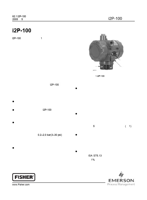
D 103197X 012Type i2P-100 Electro-Pneumatic TransducerThe Type i2P-100 electro-pneumatic transducer,shown in figure 1 uses a patented converter module that converts a milliampere input to a proportional pressure output. Both the current input and pressure output range are user-configurable in the field. The converter module uses small parts of minimum mass, which are balanced symmetrically around a pivot point at the center of the mass. This balanced arrangement results in a high performance instrument that reduces sensitivity to vibration.An integral pneumatic relay provides the high capacity necessary to drive pneumatic control valve/actuator assemblies without additional boosters or positioners. The transducer alsoprovides stable, accurate operation when its output is transmitted to small volume chambers, such as a pneumatic positioner or other pneumatic instrument.Reduced sensitivity to vibration combined with high capacity and first order lag characteristics make the i2P-100 transducer ideal for direct mounting on control valve/actuator combinations.FeaturesD Low Pneumatic Supply Consumption —The transducer has low pneumatic supply consumption which cuts operating costs.D Approved for use with Natural Gas —The i2P-100 is approved for use with natural gas as the pneumatic supply.D High Output Capability and Rangeability —The integral output relay volume of the transducer is adequate to drive valve/actuator combinations without requiring a positioner or volume booster.Selectable user field-configurable dip switch setting for output range of 0.2 to 2.0 bar (3 to 30 psi).D Split Range — Selectable user fieldconfigurable two-way split range using either half of the standard input signal.W8710INTEGRAL RELAYREPLACEABLE FILTER WITH REMOVABLE ORIFICEVENTFigure 1. Type i2P-100 Electro-Pneumatic TransducerD Corrosion Resistant —Separate housing compartments isolate the electronics from the pneumatic process. The electronics module isencased in a rugged plastic shell which protects the conformal coated electronics and dip switches from corrosion and damage. Converter module coils have corrosion resistant coating and all flexures are gold plated to provide protection from hostile environments.D Tolerant of Dirty Supply Medium —Free-flow pilot stage design and large internal air passages provide excellent tolerance to dirty pneumatic supply, by reducing the effects of contaminantbuildup and erosion. The removable primary orifice and and replaceable 5 micron filter are easy toremove for service and maintenance (see figure 1).D Easy Maintenance —Modular electronics and converter modules contained in separate housing compartments, isolating the electronics from the process, allow for easy replacement in the field for reduced maintenance costs.D Vibration Resistance —The transducer, used in a standard valve/actuator mounted application,exhibits an output shift of less than 1 percent of span when tested to SAMA Standard PMC 31.1,Condition 3.2W8693Figure 2. Type i2P-100 Electro-Pneumatic TransducerMounted on a Rotary ActuatorTIME (%)O U T P U T(% O F T Y P E i 2P -100 O U T P U T S P A N )A6815 / ILFigure 3. Output-Time Relationships for Type i2P-100TransducerValve Stroking TimeFigure 3 shows relative times for loading andexhausting an actuator. Stroking time depends upon the size of the actuator, travel, relay characteristics and the magnitude and rate of change of the input signal. If stroking time is critical, contact your Fisher sales office.W8723Figure 4. Type i2P-100 Electro-Pneumatic TransducerMounted on a Sliding Stem ActuatorInstallationRefer to figure 5 for location of standard mounting holes in the housing. See figures 2 and 4 for typical mounting configurations. Standard mountinghardware is provided for mounting on the actuator, a pipestand, or a panel. Field wiring connections are made to the terminal block accessible under the housing cap. Dimensions are shown in figure 5.Ordering InformationNote: Fisher does not assume responsibility for the selection, use, or maintenance of anyproduct. Responsibility for the selection, use, or maintenance of any Fisher product remains solely with the purchaser and end-user.To determine what ordering information is required,refer to the specification table. Carefully review the description of each specification. Specify the desired choice whenever there is a selection available. Also,specify options that are applicable to the application.375.2(2.96)55.7(2.19)33.3(1.31)67.8(2.67)75.7(2.98)22.9(0.90)33.3(1.31)33.3(1.31)0.25 18 NPT VENT OR PIPE-A-WAY CONNECTION0.25 18 NPTOUTPUT CONNECTION67 (2.62) CAP REMOVAL CLEARANCE67 (2.62) CAP REMOVAL CLEARANCE0.25 18 NPTSUPPLY CONNECTION81.6(3.21)74.2(2.92)34.7(1.37)98.7(3.89)103.9(4.09)(4.09)103.9 mm (INCH)GE06439(sheet 1 of 4)0.25 18 NPTOUTPUT CONNECTION36.3(1.43)Figure 5. DimensionsGE06439(sheet 2 of 4)238.1(9.37)69.9(2.75)126.3(4.97)101.1(3.98)6.4(0.25)204.8(8.06)240(9.45)50.8(2.00)57.2(2.25)170.8(6.72)74.2(2.92)8.6(0.34)67 (2.62)mm (INCH)COVER REMOVAL CLEARANCE (BOTH COVERS)Figure 6. Dimensions with Optional 67 Filter-Regulator (Yoke/Bracket Mounted)4146.1(5.75)91.1(3.59)209.6(8.25)GE06439(sheet 3 of 4)mm(INCH) Figure 7. Dimensions with Optional 67 Filter-Regulator (Surface/Wall Mounted)67 (2.62)COVER REMOVAL CLEARANCE (BOTH COVERS)238.1(9.37)50.8(2.00)60.5(2.38)240(9.55)243.2(9.58)17.8(6.72)74.2(2.92)GE06439 (sheet 4 of 4)mm(INCH) Figure 8. Dimensions with Optional 67 Filter-Regulator (Pipe Stand Mounted)-continued-561. Defined in ISA Standard S51.1.2. Normal m 3/hour--Normal cubic meters per hour (0_C and 1.01325 bar, absolute). Scfm--Standard cubic feet per hour (60_F and 14.7 psig).3. Performance values are obtained using a transducer with a 4 to 20 mA dc input signal and a 0.2 to 1.0 bar (3 to 15 psig) output signal at an ambient temperature of 24_C (75_F).4. This product is approved for use with Natural Gas. Natural gas to contain no more than 20 ppm of H 2S5. For other ranges, zero and span adjustments needed.6. The pressure and temperature limits in this bulletin and any applicable standard or code limitation should not be exceeded.7. Approvals are pending.Table 1. Immunity PerformancePort PhenomenonBasic Standard Performance CriteriaElectrostatic discharge (ESD)IEC 61000-4-2A Radiated EM fieldIEC 61000-4-3A EnclosureRated power frequency magnetic field IEC 61000-4-8A Burst (fast transients)IEC 61000-4-4A SurgeIEC 61000-4-5A I/O signal/control Conducted RFIEC 61000-4-6ASpecification limit = ±1% of span4 - 20 mA6.8V 6.8V 4V40 OhmFigure 9. Equivalent Circuit7FisherMarshalltown, Iowa 50158 USA Cernay 68700 FranceSao Paulo 05424 Brazil Singapore 128461Emerson Process Management The contents of this publication are presented for informational purposes only, and while every effort has been made to ensure their accuracy, they are not to be construed as warranties or guarantees, express or implied, regarding the products or services described herein or their use or applicability.We reserve the right to modify or improve the designs or specifications of such products at any time without notice.Fisher does not assume responsibility for the selection, use or maintenance of any product. Responsibility for proper selection, use and maintenance of any Fisher product remains solely with the purchaser and end-user.Fisher is a mark owned by Fisher Controls International LLC, a member of the Emerson Process Management business division of EmersonElectric Co. The Emerson logo is a trademark and service mark of Emerson Electric Co. All other marks are the property of their respective owners.。