TFT LCD 控制器 使用说明
- 格式:doc
- 大小:75.50 KB
- 文档页数:4

LCD-MonitorChassis: LPU16YS LPU17NSLPU19YS / LPU19NS LPU20YS LPU22YSModel: B1630N B1730NWB1930N / B1930NW B2030N B2230NSERVICEManualRefer to the service manual in the GSPN (see the rear cover) for the more information.1. Precautions2. Product specification s3. Disassembly and Reassemble4. Troubleshooting5. Exploded View & Part List6. Wiring DiagramContents1. Precautions1-1. Safety Precautions .........................................................................................................1-1 1-2. Servicing Precautions .....................................................................................................1-2 1-3. Static Electricity Precautions ..........................................................................................1-2 1-4. Installation Precautions ..................................................................................................1-3 2. Product specification s2-1. Feature & Specifications.................................................................................................2-1 2-2. Spec Comparison to the Old Models ..............................................................................2-3 2-3. Accessories ....................................................................................................................2-5 3. Disassembly and Assembly3-1. Disassembly ...................................................................................................................3-1 4. Troubleshooting4-1. Troubleshooting ..............................................................................................................4-1 4-2. When the Power Does Not Turn On ...............................................................................4-2 4-3. When the screen is blank ...............................................................................................4-4 4-4. Error Examples and Actions ...........................................................................................4-8 4-5. Adjustment ......................................................................................................................4-9 5. Exploded View & Part List5-1. Exploded View ................................................................................................................5-1 5-2. Parts List (B1630N) ........................................................................................................5-2 5-3. Parts List (B1730NW) .....................................................................................................5-7 5-4. Parts List (B1930N) ......................................................................................................5-10 5-5. Parts List (B1930NW) ...................................................................................................5-15 5-6. Parts List (B2030N) ......................................................................................................5-20 5-7. Parts List (B2230N) ......................................................................................................5-23 6. Wiring Diagram6-1. Wiring Diagram - Main Board .........................................................................................6-1 6-2. Wiring Diagram - IP Board ..............................................................................................6-4 6-3. Connector Functions ......................................................................................................6-5 6-4. Cables ............................................................................................................................6-5This Service Manual is a property of Samsung Electronics Co.,Ltd. Any unauthorized use of Manual can be punished under applicable International and/or domestic law.© 2009 Samsung Electronics Co.,Ltd. All rights reserved.Printed in KoreaP/N: BN82-00841A-001-11. Precautions1. Precautions1-1. Safety PrecautionsFollow these safety, servicing and ESD precautions to prevent damage and to protect against potential hazards such as electrical shock.1-1-1. WarningsFor continued safety, do not attempt to modify the circuit board.1. Disconnect the AC power and DC power jack before servicing.2. 1-1-2. Servicing the LCD MonitorWhen servicing the LCD Monitor, Disconnect the AC line cord from the AC outlet.1. It is essential that service technicians have an accurate voltage meter available at all times. Check the calibration of2. this meter periodically.1-1-3. Fire and Shock HazardBefore returning the monitor to the user, perform the following safety checks:Inspect each lead dress to make certain that the leads are not pinched or that hardware is not lodged between the 1. chassis and other metal parts in the monitor.Inspect all protective devices such as nonmetallic control knobs, insulating materials, cabinet backs, adjustment and 2. compartment covers or shields, isolation resistorcapacitor networks, mechanical insulators, etc.Leakage Current Hot Check (Figure 1-1):3. WARNING : Do not use an isolation transformer during this test.Use a leakage current tester or a metering system that complies with American National Standards Institute (ANSIWith the unit completely reassembled, plug the AC line cord directly into a 120V AC outlet. With the unit’s AC switch 4. first in the ON position and then OFF, measure the current between a known earth ground (metal water pipe, conduit, etc.) and all exposed metal parts, including: metal cabinets, screwheads and control shafts. The current measured should not exceed 0.5 milliamp.Reverse the power-plug prongs in the AC outlet and repeat the test.1-1-4. Product Safety NoticesSome electrical and mechanical parts have special safetyrelated characteristics which are often not evident from visual shock, fire and/or other hazards. Product safety is under review continuously and new instructions are issued whenever appropriate.Figure 1-1. Leakage Current Test Circuit1. Precautions1-2. Servicing PrecautionsWARNING:An electrolytic capacitor installed with the wrong polarity might explode.Caution: Before servicing units covered by this service manual, read and follow the Safety Precautions section of this manual.Note: If unforeseen circumstances create conflict between the following servicing precautions and any of the safety precautions, always follow the safety precautions.1-2-1 General Servicing Precautions1.Always unplug the unit’s AC power cord from the AC power source and disconnect the DC Power Jack before attempting to:(a) remove or reinstall any component or assembly, (b) disconnect PCB plugs or connectors, (c) connect a testcomponent in parallel with an electrolytic capacitor.2.Some components are raised above the printed circuit board for safety. An insulation tube or tape is sometimes used. The internal wiring is sometimes clamped to prevent contact with thermally hot components. Reinstall all such elements to their original position.After servicing, always check that the screws, components and wiring have been correctly reinstalled. Make sure that 3.the area around the serviced part has not been damaged.4.Check the insulation between the blades of the AC plug and accessible conductive parts (examples: metal panels, input terminals and earphone jacks).5.Insulation Checking Procedure: Disconnect the power cord from the AC source and turn the power switch ON.Connect an insulation resistance meter (500 V) to theblades of the AC plug.The insulation resistance between each blade of the AC plug and accessible conductive parts (see above) should be greater than 1 megohm.6.Always connect a test instrument’s ground lead to the instrument chassis ground before connecting the positive lead;always remove the instrument’s ground lead last.1-3. Static Electricity PrecautionsSome semiconductor (solid state) devices can be easily damaged by static electricity. Such components are commonly called Electrostatically Sensitive Devices (ESD). Examples of typical ESD are integrated circuits and some field-effect transistors. The following techniques will reduce the incidence of component damage caused by static electricity.1.Immediately before handling any semiconductor components or assemblies, drain the electrostatic charge from your body by touching a known earth ground. Alternatively, wear a discharging wrist-strap device. To avoid a shock hazard, be sure to remove the wrist strap before applying power to the monitor.2.After removing an ESD-equipped assembly, place it on a conductive surface such as aluminum foil to prevent accumulation of an electrostatic charge.3.Do not use freon-propelled chemicals. These can generate electrical charges sufficient to damage ESDs.4.Use only a grounded-tip soldering iron to solder or desolder ESDs.5.Use only an anti-static solder removal device. Some solder removal devices not classified as “anti-static” can generate electrical charges sufficient to damage ESDs.Do not remove a replacement ESD from its protective package until you are ready to install it. Most replacement ESDs 6.are packaged with leads that are electrically shorted together by conductive foam, aluminum foil or other conductive materials.Immediately before removing the protective material from the leads of a replacement ESD, touch the protective7.material to the chassis or circuit assembly into which the device will be installed.Caution: Be sure no power is applied to the chassis or circuit and observe all other safety precautions.Minimize body motions when handling unpackaged replacement ESDs. Motions such as brushing clothes together, 8.or lifting your foot from a carpeted floor can generate enough static electricity to damage an ESD.1-21. Precautions 1-4. Installation Precautions1.For safety reasons, more than two people are required for carrying the product.2.Keep the power cord away from any heat emitting devices, as a melted covering may cause fire or electric shock.3.Do not place the product in areas with poor ventilation such as a bookshelf or closet. The increased internaltemperature may cause fire.4.Bend the external antenna cable when connecting it to the product. This is a measure to protect it from being exposed to moisture. Otherwise, it may cause a fire or electric shock.Make sure to turn the power off and unplug the power cord from the outlet before repositioning the product. Also check 5.the antenna cable or the external connectors if they are fully unplugged. Damage to the cord may cause fire or electric shock.6.Keep the antenna far away from any high-voltage cables and install it firmly. Contact with the highvoltage cable or the antenna falling over may cause fire or electric shock.7.When installing the product, leave enough space (10cm) between the product and the wall for ventilation purposes.A rise in temperature within the product may cause fire.1-31. Precautions Memo1-42. Product specifications 2. Product specifications2-1. Feature & Specifications2-12. Product specifications2-22. Product specifications 2-2. Spec Comparison to the Old Models1360 x 7682-32. Product specifications*Color Effect- Grey scale: Images are displayed in a grey tone on the screen.- Green: Images are displayed in a green tone on the screen.- Aqua: Images are displayed in a blue tone on the screen.- Sepia: Images are displayed in a brown tone on the screen.Image Size : If the resolution is not wide resolution, this option allows the screen size to be selected as normal or wide.*MagicAngle- Lean Back Mode1: Select when viewing from a slightly lower angle.- Lean Back Mode2: Select when viewing from the bottom.- Standing Mode: Select when viewing from the top.- Side Mode: Select when viewing from the left or right.- Custom: W hen <Custom> is selected, settings for <Lean Back Mode 1> is applied by default.User can set suitable picture quality as needed.*MagicEco- 100%: the power consumption is 100% of Default Setting.- 75%: the power consumption is 75% of Default Setting.- 50%: the power consumption is 50% of Default Setting.2. Product specifications 2-3. Accessories2. Product specifications Memo3. Disassembly and Assembly 3. Disassembly and AssemblyA s this monitor has parts that are sensitive to static electricity, be careful when handling them.3-1. Disassembly1. Turn the monitor off before beginning the disassembly process.2. When disassembling the monitor, do not use any metal tools except for the provided jig.3. Disassemble the monitor carefully as directed in the following procedures.3. Disassembly and AssemblyLAMPWIRELVDSFUNCTION3. Disassembly and Assembly IP-BOARDMAIN-BOARD3. Disassembly and Assembly Memo4. Troubleshooting4. Troubleshooting4-1. TroubleshootingSet custom mode as follows before beginning a repair.1. B1630N/B1930N B1730NW/B1930NW B2030NB2230NResolution:1360x768V-frequency:60HzH-frequency:47.7kHzResolution:1440x900V-frequency:75Hz H-frequency:70.6kHzResolution:1600x900V-frequency:60Hz H-frequency:60kHzResolution:1920 x 1080V-frequency:60Hz H-frequency:67.5kHzIf the screen is blank, check whether the power cord is connected correctly.2. The circuits to check:3. • When the raster does not appear: The Function PCB, Main PCB, I/P PBA • When 5V is generated but a blank screen is displayed: Main PCB • When 5V is not generated: I/P PBA4. factory mode.4. Troubleshooting4-2. When the Power Does Not Turn OnIC601IC602Yes4. Troubleshooting 4-2-1. Circuit diagrams when the power does not turn on1234-3. When the screen is blankCN400IC400X4004-3-1. When a blank screen is displayed2314B1730NW / B1930NW / B2030N / B2230NB1630N / B1930N4-3-2. Waveforms when no screen is displayed 1344-4. Error Examples and Actions4-5. Adjustment4-5-1. Service Adjustment Conditions1.Precautions before a Service Adjustment1) Check whether the devices for the service adjustment are operating normally.2) Secure a space that is sufficiently wide for disassembling the monitor.3) Prepare a soft mat on which the monitor will be disassembled.2.Entering Service ModeEntering:Menu Brightness 0Contrast 0Hold down the Enter button for five (5) seconds.Exiting:Power OFF Power ON3.Basic Service Items to Perform after Replacing a Board1) Check the PC color adjustment status.2) Input DDC (input both of Analog and Digital).3) Check whether the appropriate MCU code for the model is input.4) Hard power the monitor off after entering service mode and performing a reset.4.DDC EDIT Data Input1) Use when updating the AD board code.2) D ownload the WinDDC program, DDC Input program, and Hex and DDC files appropriate to the model through theQuality Control department of Samsung Electronics. Install the jig and input the data, as shown in the figure.4-5-2. Service Function SpecificationsChecking the Code Version1. Check the MCU code version and checksum after entering SVC Mode.2. E ntering SVC Mode- Adjust the Brightness and Contrast values to 0. - Hold down the Enter button for five (5) seconds. - The SVC Function OSD is displayed.- T o exit the SVC Function, turn the power off.3. S afe Mode - W hen the input signal is higher than the supported frequency of the product, safe mode gives users some time (one minute) to change the video card settings to the Recommended Mode settings.Service Mode (Moving around)1. Press the - button to move to other items.2. Press the - button to change the setting to On or Off.When replacing the panelAfter replacing the panel, move to the Panel item and hold down the Menu button for five (5) seconds. The Ch. No is incremented by 1 and then both the On Time and Cycle are set to 0.This number is incremented by 1.12345Use the DDC Manager MTI-2050 version or later.1) Click the Open [F5] icon.2) Select a port.3) Open a DDC file.4) Select a date and click the OK [Save] button.5) Click the Next [OK] button.66) Enter the serial number and then press the Enter button※When inputting digital data after inputting analog data, repeat steps 2 to 5.1) Check the following options after open the “Easywriter” - Option: Setup ISP tool1- LPT Port Offset: 378- ISP Jig type Selection: SAMSUNG- Auto detect- Confirm Change4. Troubleshooting2) Click the Load File button.23) Select an MCU code file, and then click the Open[O] button.4. Troubleshooting 4) Click the Auto button.45) When programming and verification are complete, hard power the monitor off and then on again.4. Troubleshooting Memo5. Exploded View & Part List5. Exploded View & Part List5-1. LS20PUYKF/EN - Exploded ViewT 0003M 0215M 0014M 0174M 0107M 0013S T DM 00275. Exploded View & Part List5-1-1. LS20PUYKF/EN - Parts List5. Exploded View & Part List 5-2. LS20PUYKF/EN - Parts ListService Bom (SA: SERVICE AVAILABLE, SNA: SERVICE NOT AVAILABLE)5. Exploded View & Part List5. Exploded View & Part List5. Exploded View & Part List5. Exploded View & Part List5. Exploded View & Part List5-1. LS20PUYKF/EN - Exploded ViewT 0003M 0215M 0014M 0174M 0107M 0013S T DM 00275. Exploded View & Part List5-1-1. LS20PUYKF/EN - Parts List5. Exploded View & Part List 5-2. LS20PUYKF/EN - Parts ListService Bom (SA: SERVICE AVAILABLE, SNA: SERVICE NOT AVAILABLE)5. Exploded View & Part List5. Exploded View & Part List5. Exploded View & Part List6. Wiring Diagram 6. Wiring Diagram6-1. Wiring Diagram - Main Board6. Wiring Diagram6. Wiring Diagram6. Wiring Diagram6-2. Wiring Diagram - IP BoardLVDS Connector RGB Connector (Connect to PC)Function Connector (Connect to IP-Board)6. Wiring Diagram 6-3. Connector Functions6-4. CablesBN96-02854W(B1730NW / B1930NW / B2030NBN96-07252U (B1930N)BN96-07252X (B2230N)。

3.5-INCH TFT-LCDTEST MONITORINSTRUCTION MANUALSpecially made for Surveillance systemPlease read the following items before use.●Dear customers, thanks for using this product, we sincerely hope our products can bring you convenience, and before start to use it, please pay attention to the following items.And please keep it after reading the safety notice.1)Forbidden to use in the high temperature environment especially not allowed in hi-temperature bathroom, the most suitable working temperature for this product is approximate 0-60℃If something breaks down, please turn off the monitor, and take out the batteries, or pull out the plug of the charger. When product leaks smoke 、exception smell or other exception matter . If continue using, it may cause fire disaster or suffer shockDon’t redo or knock down the machine (Do not open the case ), if the machine breaks down or the case gets broken. Please don’t continue using ,otherwise it may cause the fire disaster or suffer shock.2)Don’t redo、heat up、over-tweak or drag the connection wire, and please don’t put heavy object on the connection wire, otherwise it may damage the wire, and cause fire disaster or suffer shock. when wire damaged, please contact the local wholesaler to change.3)Please don’t place the product in disbalance place, otherwise it may make the machine drop to get damage.4)Please use the dominated batteries, and when fixing the batteries, please do in accordance with demonstration.Please don’t heat up 、redo or knock down the battery, please don’t drop the battery or make it get hit, please don’t place the battery in the metal container. Use the dominated charger to charge the battery. any fails from the above case may cause battery explosion or leak, thereby cause the fire disaster or body harmness.5)Please use the dominated battery or AC charger. Please don’t use it at the voltage beyond the fixed range.6)If battery leaks, and the liquid comes into your eyes、skin or clothes, please wash the position touched, if necessary, please contact the doctor or dial the emergent number.7)When plug get damaged or it’s loosen when inserted into the socket, please don’t use the AC charger, otherwise it may cause fire disaster or suffer shock.8)Clean the monitor. and when not used for a long time, please take out the batteries, or pull out the plug, otherwise it may cause fire disaster or suffer shock.9)When charging finished, please pull out the plug from the socket, otherwise fire disaster may happen.10)Keep the product away from water or other liquid, otherwise there may be danger of fire disaster or shock.In order to keep your safety, please use the adapter we supplied (Regarding the damages caused by using adapters from other supplier, we are not responsible to it).11)Don’t set the machine in the place of bared sunshine.12)In order to keep it away from damage by dropping or bumping at sharp object, Please place the machine in the place where the children can not reach,When the battery’s working time is apparently shorter than new one, please change the battery.13)The machine will get heat after long time working, it belongs to normal phenomenon.14)Please don’t place the charger in the place of much dust or intensity vibration、extreme humidity or high temperature (for example: under the bare sunshine or beside the heater )15)The available voltage for the charger is AC 110~240 V / 50/60 Hz. Plug standard is various from different environment; when purchase this product, please consult relevant department to confirm the suitable plug standard. 16)During charging, the batteries and charger will get heat, it belongs to normal phenomenon, but not malfunction. If possible, please charge the battery in aeration area.Battery and power supplyThe following items state the right way to use batteries and the way to extend its lifespan Using the batteries in incorrect way will shorten its lifespan or cause to leak、overheat、fire or explode.●Battery comes out from factory with no power. Please charge it before use. and put it into the battery box whe n don’tuse it.Battery usage notice-If leaving the battery to be idle, it will lose electricity gradually. Please charge it at 1-2 day early before use·When battery in idle status, turn off the monitor, it’s a way to extend the lifespan.·The performance will reduce when battery in low temperature environment; battery can’t work normally in cold condition. place a fully charged battery in warm place. Don’t place battery close to heater or hand-warming articles.Charging Notice·Please put the batteries into the machine,and then connect the charger well.this product adopts IC to conduct electrical source management.when fit on the battery,it will conduct auto-inspection(the red light flash 2 times),if battery goes worng,the red light flash quickly;if working normally,the LED indicator light keep red.if fully charged,the red light will go out.10 minutes more charging again it’s a way to check if the charged battery is full or not.The charge time will extend if the surrounding temperature lower than 10℃ or higher than 35℃,please don’t charge the battery in the place where temperature is higher than 40℃;it stops charging when temperature under 0 ℃.it’s not allowed to charge the fully charged battery again,and you don’t have to wait to charge until the el ectricity totally runs out.·It’a normal phenomenon that battery gets heat when charge over or after use.Battery’s lifespanIn normal temperature,users can charge battery for 300 times.when the working time of consuming its full capacity apparently decrease,users need to change the battery.Storage·If long time no use after fully charged, the battery’s perfermance will weaken.·If don’t use this machine for a long time,please take the batteries ou t,and store them in a dry place,moreover the store temperature should between 15℃ and 25℃.Please don’t place it in extremely high or low temperature area.Attention:battery usage notice-Don’t transport or store the battery together with necklace、barrette and other metal object.·Don’t throw the battery into fire to heat up.·Don’t knock down or redo the battery.·Please use the dominated charger to charge.·Deal with the batteries discarded.·Don’t drop the battery or make it suffer intense vibration.·Please keep it away from water.·Please keep its connection terminal clean.·It’s the normal phenomenon that the battery and machine get heat after long time working.Alternating Current Adapter·Please just use the adapter dominated for this machine,if use other kind of adapter may cause matters to the machine. ·AC adapter for indoor use.·Make sure that DC plug connect to the monitor firmly.·Please turn off the monitor before pull out the plug.·Don’t use it in other devices.·Don’t knock it down yourself.·Don’t place it in high temperature or humidy area.·Please don’t let it suffer intense shake·It’s a normal phenomenon that the adapter buzzs or get heat when using.·If adapter cause wireless interference,please reset the antenna.Product UseIn order to make sure of the normal working,please don’t let the machine get hit or shake.Electric interferenceThis product may cause interference to the medical and aviatic devices.before you use it in the hospital or airport,please consult the hospital the airline company.Liquid crystalIf screen suffered damage,please avoid to touch the liquid crystal.if any case of the following happens,please do as we show.·If liquid crystal gets to your skin,please clean the position with cloth,then daub some soap and then wash it.·If liquid crystal comes into your eyes, please flush the eye with water more than 15minutes,and then ask for help from doctor.·If drink the liquid crystal by mistake,please gargle with water,and drink much water to help throw up,and then consult the doctor.Debug The MachineBefore start to monitor the important spot,please adjust the machine to make sure of its normal working.we are not responsible to any damage or benefit loss caused by product’s malfunction.ClaimSpecification subject to change without notice, we have the final explaination right to do a explaination to this manual. ·The screen is made from high precise technology,still there would be brightness dot or color abnormity on screen sometimes.it’s the normal phenomenon to this kind of LCD,but not failure.·When fall acrosse wireless interference( such as magnetic field、static or circuit noise),the abnormity display may happen.AccessoryPower Charger 1pcWall mount bracket 1pc1.2V AA nickel-hydrogen battery 4pcsA V cable #1( video input) : 1pcAv cable #2 (video output): 1pcWrist strap 1 pcUsers’manual 1pcWarranty card 1pcAppearance and function illustrationMenu adjustmentBrightness Brightness adjustment: Users can change the brightness and darkness of image by adjusting the parameter according to his personal requirement. Firstly, press MENU key to enter main menu interface, and then press “▲”key or “▼”key to confirm this submenu, then press “▲”or “▼”to adjust the brightness and darkness of image. Press ESC key to exist main menu.Contrast Contrast adjustment: Users can change the contrast of image by adjusting the parameter according to his personal requirement. Firstly, press MENU key to enter main menu interface, press MENU key to select downwards(moving the yellow cursor to this submenu),and then press “▲”key or “▼”key to confirm this submenu, in the end press “▲”or “▼”to adjust the contrast of image. Press ESC key to exist main menu.Saturation Saturation adjustment: Users can change the saturation of image by adjusting the parameter according to his personal requirement. Firstly, press MENU key to enter main menu interface, press MENU key to selectdo wnwards(moving the yellow cursor to this submenu),and then press “▲”key or “▼”key to confirm this submenu, in the end, press “▲”or “▼”to adjust the saturation of image. Press ESC key to exist main menu.Sharpness Sharpness: Users can change the sharpness of image by adjusting the parameter according to his personal requirement. Firstly, press MENU key to enter main menu interface, press MENU key to select downwards(moving the yellow cursor to this submenu),and then press “▲”key or “▼”key to confirm this submenu, in the end, press “▲”or “▼”to adjust the sharpness of image. Press ESC key to exist main menu.V olume V olume adjustment: Users can change the volume of image by adjusting the parameter according to his personal requirement. Firstly, press MENU key to enter main menu interface, press MENU key to select downwards(moving the yellow cursor to this submenu),and then press “▲”key or “▼”key to confirm this submenu, then press “▲”or “▼”to adjust the volume of image. Press ESC key to exist main menu.Language English / Italian / ChineseInstallation Illustration Battery fixing1.Product fixing methodUsers have four methods to fix this product, you can choose the accessories supplied to fix according to the various situation.⑴Portable: APut it on your arms by using the wrist strap.(this method is usually suitable to outdoor working or or indoor camera lens adjustment in construction field)⑵ Portable: BHanging the machine at your waist.(3) Fixing on wall :Fix the machine on wall by using the wall bracket.(4)Normal MethodOpen the multi-function bracket to stand the machine on the table-board.2.OPERATION1、Put the batteries into machine according to the direction marked with “+” “-”.2、Insert the A V cable 1 (including power output cable) to the jack in position 9of the illustration. And then connect the red RCA connecter to video signal port, and the white one to audio port.3、Switch the power switch to “ON” side.4、If you need to output A V signal , insert A V cable 2 to the jack in position 10 of the illustration. Yellow cable for video output, white one for audio output.5、If powerless, you can charge it as it’s working. Conn ect the charger to position 7 of the illustration.6、When the image comes to be normal, you can adjust it by key 3、4、5 and 6.showed in the illustration.SpecificationTrouble shootingBefore calling for repair, please refer to this section to see whether you can solve it by yourself; if you need help, please contact our after sale service centre or our wholesaler.。
一.LCD控制器(TFT)型号:FX-T3224C256A;FX-T4024C256A;FX-T4824C256A;FX-T6448C256A;FX-F8060C256A
信息发布内容:
1) 深圳方显科技产品支持多款TFT数字屏和模拟屏, 单片机、DSP、嵌入式系统都能轻松实现TFT LCD显示,方显科技公司提供强有力的技术支持和各种系统解决方案,帮助客户快速开发出符合市场需求的产品!
名称: FX-T3224C256A
型号: 彩色TFT 320*240
产品特性: . 支持256色
. 总线/并口接口
. 单点读写
. 写时地址自动加1, 写满一行自动换行读时地址不变
2)深圳方显科技FX-T系列是一种功能强大、编程简单、读写速度快的TFT液晶显示控制板,用户CPU由8/16位数据口直接控制显存,用户可根据需要自
由切换或更改显示画面部分或全部,无须刷新整个画面。
支持3.5"-12"屏。
单
片机MCU、DSP、ARM、嵌入式系统过8位数据口轻松实现TFT LCD显示,有如操作I/O一样容易。
显示内容可由您任意确定到每一个像素,写时地址自动加
1, 写满一行自动换行,读时地址不变。
模拟屏数字屏可选,大大节约开发成
本。
广泛应用于医疗、安防、仪表、工控设备、POS机、数控设备。

TFT LCD控制器说明书V1.2在使用彩色TFT液晶显示器的时候需要为其提供多种时序,大容量高速显存(GRAM)。
当所选处理器(如:ARM7,DSP,8/16位MCU)不带LCD控制器时将会给方案带来一定的难度。
再者当处理器自带的LCD控制器因为60Hz不间断刷屏时序消耗了较多系统资源时(存储器总线带宽),这必定将大大降低系统性能。
通常自带LCD控制器的处理器(如:ARM9)都会使得系统变得相对较庞大、复杂,这时就不得不使用操作系统、文件系统、GUI等搭配使用,一定程度上增加了系统的庞大性、复杂度及成本。
该TFT LCD控制器能降低系统复杂度、简化系统设计、降低成本和加快产品上市,提高了用户产品的竞争优势,同时却不会带来产品性能上的下降。
该控制器可以提供几乎全部可能的TFT LCD时序及较大容量显存,使不带TFT LCD控制器的处理器能轻松使用真彩TFT LCD的构想成为可能。
一、功能特性1.16位双向并行总线用于设置工作寄存器和读/写GRAM数据;2.写GRAM时可分别掩摸高/低字节(当工作在8bpp、24bpp时能提高写入速度);3.灵活的写GRAM地址增量方式,可选的读GRAM地址增量方式;4.内部构建多个FIFO和DMA,使得读/写GRAM时无需判忙,大数据量传输无雪花;5.提供1个SYNC信号输出,可提高刷屏换图时的画面质量;6.最大支持2MB显存(IS61LV51216 * 2),考虑成本通常使用IS61LV25616(1或2片);7.GRAM按16位数据结构寻址,所有单元可读/写;8.可选择单片SRAM的容量(A18=0:256K*16;A18=1:512K*16);9.优化的读GRAM功能,能极大程度提高读操作的效率;10.可以轻松驱动点时钟<=32MHz的任意TFT屏,如常规分辨率:800*600、800*480、640*480、480*272、480*232、320*240等;11.可工作在8bpp、16bpp、24bpp模式(分别占用1、2、3字节GRAM);12.可将8bpp、16bpp数据转换为24bpp输出;13.当使能8/16bpp转24bpp时,24bpp的RGB低位值可设置任意固定逻辑状态;14.LCD行参数可设置(THP、THB、THD、THF);15.LCD帧参数可设置(TVP、TVB、TVD、TVF);16.LCD点时钟分频数可设置,可以提供最高32MHz的时钟(64MHz主频);17.LCD时序信号可设为反相输出(CK、HS、VS、DE);18.提供一个DISP状态信号输出(类似LQ043T等LCD需要此信号);19.LCD引脚可以使能/关闭(避免上电就工作在不一定正确的时序下);20.提供插针式的LCD信号输出接口,可以连接到其他任意LCD屏;21.提供一个触摸屏电路,可以选择为ADS7843输出或4线电阻式输出;22.板载背光DC/DC变换,且背光亮度可调整(可调范围:关闭、1~15亮度);23.板载+5V DC/DC变换,因此工作电压可以降低到3.1V;24.LCD起始地址可设置(多图层时可做轮流切换);25.程序版本和分频因子可读取;26.LED工作指示(LCD帧频率除4,默认15Hz)。

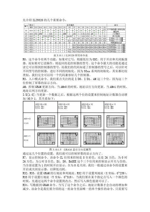
先介绍ILI9320的几个重要命令:R0,这个命令有两个功能,如果对它写,则最低位为OSC,用于开启和关闭振荡器。
而如果对它读操作,则返回的是控制器的型号。
这个命令最大的功能是通过读它可以得到控制器的型号,而我们的代码知道了控制器的型号之后,可以针对不同型号的控制器,进行不同的初始化。
因为93xx系列的初始化,其实都比较类似,我们完全可以用一个代码兼容好几个控制器。
R3,入口模式命令。
我们重点关注的是I/D0、I/D1、AM这三个位,因为这三个位控制了屏幕的显示方向。
AM:控制GRAM更新方向。
当AM=0的时候,地址以行方向更新。
当AM=1的时候,地址以列方向更新。
I/D[1:0]:当更新一个数据之后,根据这两个位的设置来控制地址计数器自动增加/减少1,其关系如下:通过这几个位置的设置,我们就可以控制屏幕的显示方向了。
R7,显示控制命令。
该命令CL位用来控制是8位彩色,还是26万色。
为0时26万色,为1时8位色。
D1、D0、BASEE这个三个位用来控制显示开关与否的。
当全部设置为1的时候开启显示,全为0是关闭。
我们一般通过该命令的设置来开启或关闭显示器,以降低功耗。
R32,R33,设置GRAM的行地址和列地址。
R32用于设置列地址(X坐标,0~239),R33用于设置行地址(Y坐标,0~319)。
当我们要在某个指定点写入一个颜色的时候,先通过这两个命令设置到改点,然后写入颜色值就可以了。
R34,写数据到GRAM命令,当写了这个命令之后,地址计数器才会自动的增加和减少。
该命令是我们要介绍的这一组命令里面唯一的单个操作的命令,只需要写入该值就可以了,其他的都是要先写入命令编号,然后写入操作数。
R80~R83,行列GRAM地址位置设置。
这几个命令用于设定你显示区域的大小,我们整个屏的大小为240*320,但是有时候我们只需要在其中的一部分区域写入数据,如果先用写坐标,后写数据这样的方式来实现,则速度大打折扣。
目錄㊟意事㊠ (2)安裝方法 (2)連接電源 (2)調整螢幕角度 (2)保養與維護 (2)產品搬運方式 (3)簡介 (4)產品介紹 (4)認識各零件和控制鈕 (5)設定 (7)設定輸入訊號先後順序 (8)M ICROSOFT W INDOWS 95/98/2000/ME/XP的安裝㈾訊(.INF) 檔案 (8)㉂訂顯示器 (9)選擇OSD 功能 (9)OSD 功能表 (10)螢幕設定 (10)色調 (10)OSD 設定 (10)輸入選擇 (11)Misc 設定 (11)亮度和對比 (11)㈬平和垂直位置 (11)㈬平點數和相位 (11)㉂動調整 (12)明亮對比設定 (12)選擇色調 (12)採用使用者定義色調 (13)OSD 位置 (13)OSD 時間 (13)OSD 透明度設定 (13)選擇語言 (13)輸入選擇 (14)恢復預設 (14)㈾訊 (14)背光 (14)清晰度 (14)全螢幕 (14)文字 / 圖形模式 (15)4 警告訊息和疑難排解 (16)警告訊息 (16)疑難排解 (17)技術規格 (19)規格 (19)相關規章 (20)符合FCC 規格 (20)㊟意事㊠安裝方法· 請勿覆蓋或擋住顯示器前方的通風口。
· 請勿將顯示器安裝於熱源處(例如暖器或風管),同時也不可直接曝曬於㈰光㆘、累積過多灰塵,或者承受撞擊。
連接電源· 使用符合當㆞電壓的正確電源線。
· 儘量使用最靠近顯示器的插座。
· 不可在電源線㆖壓置任何物品。
· 在㆘列情況㆘,請從插座㆗拔除電源線:Ø 長期不使用顯示器。
Ø 電源線損壞或邊緣磨損。
Ø 顯示器掉落或者外殼受損。
Ø 性能產生嚴重落差,必須送修。
調整螢幕角度· 使用顯示器的角度調整功能,以便將角度調整㉃㊜當的位置。
用兩隻手扶住螢幕㆖方兩個角落,並調整㉃㊜當的角度。
3.2inch TFT Touch ShieldUser ManualOVERVIREThis is a 3.2inch resistive screen TFT LCD, 320x240 resolution, integrate controller on board. It uses SPI interface, can be used to display image, text or draw geometric figure with functions.STM32 and Arduino examples are provided for users.PARAMETERSLCD Type: TFTLCD Interface: SPILCD Controller: ILI9341Touch Screen Controller: XPT2046Touch Screen Type: ResistiveResolution: 320x240 (Pixel)Color Gradation Exponent: 65536INTERFACESymbol Arduino PIN STM32 PIN Description 5V 5V 5V 5V power inputGND GND GND GroundSCLK D13 PA5 SPI clockMISO D12 PA6 SPI data inputMOSI D11 PA7 SPI data outputLCD_CS D10 PB6 LCD chip selectLCD_BL D9 PC7 LCD back lightLCD_RST D8 PA9 LCD resetLCD_DC D7 PA8 LCD data/commandselectionHOW TO USEHARDWARE CONFIGURATION•If there is ICSP interface on Arduino board, set the SPI Config switch to ICSP position.(default)•If Arduino board has no ICSP interface, set the SPI Config switch to the position that SCLK\D13, MISO\D12, MOSI\D11EXAMPLESWe provide Arduino UNO examples and XNUCLEO-F103RB examples for this screen.ARDUINO EXAMPLES1.Download the examples: 3.2inch TFT Touch Shield code.7z, and copy the libraries which arein Arduino\lib folder of examples to the libraries folder which is under the installationdirectory of Arduino.2.Before running the LCD_ShowBMP code, copy the pictures which is in the PIC folder to SDcard.3.Open the LCD_ShowBMP project with Arduino IDE, download to Arduino board.4.The Touch code use four sets of calibration values, could support painting operation in fourdirections. There are five colors which could be chosen on the right. The size of paintbrush is9 by default. Users can also click the AD on screen to calibrate:Please use the stylus click the cross on the screen. The cross will always move until thescreen adjustment is completed.5.According to the prompt, click the red “+” one by one to finish the calibration.STM32 EXAMPLES1.Before running the code that display image. copy the pictures which is in the PIC folder toSD card. Then insert the LCD to NUCLEO or XNUCLEO board.2.Open the project with MDK, download to the NUCLEO or XNUCLEO development board.3.The LCD will first show some general functions: Draw dots, draw dotted line and full line,rectangle, filled rectangle, circle and filled circle. Every figure keeps for 3s. You can change the size of dot, the width of lines and the size of the circles.4.The Touch code use four sets of calibration values, could support painting operation in fourdirections. There are five colors which could be chosen on the right. The size of paintbrush is9 by default. Users can also click the AD on screen to calibrate:Please use the stylus click the cross on the screen. The cross will always move until thescreen adjustment is completed.5.According to the prompt, click the red “+” one by one to finish the calibration.Note:Image: 320x240, 24bit, bmp.SD card: FAT。
COLOR TFT LCD MONITOR User ManualGeneral InformationThank you for choosing our TFT LCD (liquid crystal display) monitor. This product employs integrate circuits, low power consumption, and no radiation emission. It has fashion designed appearance and good portability. The TFT LCD screen is the most suitable display for VGA, VCD, DVD, and GPS on vehicles or vessels. Moreover, this product is able to be used in office, at home, or other proper positions. Please enjoy the benefits of convenience, safety, and space-saving from this TFT LCD monitor in different ways.To ensure the best use of this product, please read this manual carefully beforehand.CAUTIONS1. Please use the adapter attached in the accessories.2. Please do NOT expose this product to direct sunlight, heat, or humidconditions.3. Please keep away from strong light while using this product in order to obtainthe clearest and the most colorful pictures.4. Please avoid heavy impact or drop onto the ground.5. Please do NOT use chemical solutions to clean this product. Please wipe with aclean soft cloth to maintain the brightness of the surface.6. Please follow the instructions and trouble-shootings to adjust the product. Otherimproper adjustment may result in damage. Any further adjustment must be performed or conducted by a qualified technician.7. Please unplug the power and remove the battery if long-term no-use, or thunderweather.Table of Contents1. PRODUCT DESCRIPTION -----------------------------------------2. REMOTE CONTROL-------------------------------------------------3. POWER SOURCE ----------------------------------------------------4. BATTERY INSTRUCTION-----------------------------------------5. SETTING MENU -------------------------------------------------6. ACCESSORIES --------------------------------------------------------7. PARAMETER ----------------------------------------------------------8. TROUBLESHOOTING ----------------------------------------------9.REMARK---------------------------------------------------------------1. PRODUCT DESCRIPTION1.Infrared signal receiver (work with remote control)2.Battery indicator light: red while standby; green while working3.–: V olume down, or value down while using menu setting functions4.+: V olume up, or value up while using menu setting functions5.MENU:To activate OSD (on-screen display) menu; Long-press to switch overscan / underscan pictures when receiving HDMI or SDI signal.6.<: To select items on OSD menu; Press to switch the image monochrome (red、green、blue、monochromatic and color); Long-press to achievefull-screen display7.>: To select items on OSD menu; Press to adjust brightness among 6 levels .Long-press for 5-6 seconds to achieve 5D camera mode underHDMI function.8.A/V: circularly switch among HDMI, YPbPr, Video 1, Video 2, and SDI (optional).9.Power ON/OFF switch. (Reboot to restore normal screen mode)10.Sun shade.11.Mounting socket (right side)12.SDI (Serial Digital Interface) signal input 13.SDI signal output14.Y signal input15.Video 1 signal input16.Pb signal input17.Video 2 signal inpu18.Pr signal input19.Audio signal input20.Battery power on/off switch21.HDMI (High Definition Multimedia Interface) signal input22.4-pin XLR DC power input23.DC power input24.Battery slot25.Mounting socket (bottom)2. REMOTE CONTROL1.Power2.Mute button3.Display switch among HDMI、YPbPr、Video 1, Video 2, and SDI (optional, must with necessary equipment) circularly4.MENU: enter menu function setting5.▲: Up move; or change brightness among 6 levels6.▼: Down move7.◄: Left move; or volume down; or increase the function values in menu settings8.►: Right move; or volume up; or decrease the function values in menu settings3. POWER SOURCESThis product package comes with a 12V DC adapter plug in to the DC power input (See PRODUCT DESCRIPTION 23).Another option of power source is using batteries. The product package comes with two types of batter slots (See BATTERY INSTRUCTION). The recommended batteries are Panasonic DU21 and Sony QM91D.Also, this product is capable to use the power from your camcorder via the 4-pin XLR interface (See PRODUCT DESCRIPTION 22).4. BATTERY INSTRUCTION1.Battery slot and batteryThe included two battery slots available for two types of batteries (See the pictures below).Picture: two types of battery slotsPicture: two types of batteries corresponding to the upper two slots2.Battery power controlThe battery switch controls whether to use battery power or not. Keep off while not using battery.Suggestion: Better take off the battery for long-time not using this product.2.Battery volumeAn icon of battery volume displays on the screen while using battery as power source.5. SETTING MENUBefore setting the menu functions, please make sure the device is connected correctly.When power on, press MENU on the device (See PRODUCT DESCRIPTION 5) or on the remote control (See REMOTE CONTROL 4). The menu of function setting will display on the screen.Press >/< buttons on the device or ▼/▲ buttons on the remote control to select items on the left of the display. Then press + / – buttons on the device or ►/◄buttons on the remote control to change the values.Battery power low Battery power fullThe following pictures are the setting displays of different modes. 1.OSD YPbPr/HDMI/SDI setting menuPicture: YPbPr/HDMI/SDI setting screen2.OSD A V setting menu (Video 1/Video 2)The auto-detected A V format displays at the bottom of the screen.Picture: A V setting screen3.Miscellaneous setting menu under YPbPr/HDMI/SDI modes, enter via item to a new page.Picture: Miscellaneous setting screen6. AccessoriesPicture: Accessories included in the product packageOn the above picture, from top to bottom, left to right, the included accessories are:Remote control 1 pieceBracket 1 piece4-pin battery slot 1 piece2-pin battery slot 1 pieceSun shade 1 pieceUser manual 1 piece12V DC adapter 1 piecePicture: Optional accessoriesThe optional accessories on the above picture are shoe mount, battery, and HDMI cable.7. MAIN PARAMETERS8. TROUBLE SHOOTING1. Only black-and-white display:Check whether the color saturation and brightness are properly setup.2. Power on but no pictures:Check whether the cables of Video, HDMI, DVI (Digital Visual Interface), and/or SDI (optional) are correctly connected. Please use the standard power adapter coming with the product package. Improper power input may cause the device. 3. Wrong or abnormal colors:Check whether the cables are correctly and properly connected. Broken or loose pins of the cables may cause a bad connection.4. Remote control doesn't work:Check whether the battery is well charged and properly installed into the device. The signal of the remote control may interfered by some obstacles or obstructions. 5. Other problems:Please press “MENU”button and choose to reset to manufactory default values.9. REMARKIt is normal to see some bright lines appear on the screen when turn off the device.Note: due to constant effort to improve products and product features, specifications may change without notice.。
TFT LCD 控制器使用说明
一、概述
TFT LCD 控制板由CPLD产生稳定的TFT时序驱动LCD面板,以及SDRAM(显存)时序读取显存的数据。
并能接受MCU写入的数据,保存到SDRAM的指定位置。
TFT LCD 控制板在系统中的应用如下图所示:
TFT LCD 控制板可以通过用户板的扁平电缆供电,也可以单独供电。
可以连接5V的MCU,也可以连接3.3V的MCU;可以驱动5V的LCD屏,也可以驱动3.3V的LCD屏。
接口电压类型、TFT LCD面板类型(不同的分辨率、位数、时序)均可定制。
二、TFT LCD 控制板接口说明。
控制板PCB尺寸和引脚位置图
TFT LCD 控制板和MCU系统板的连接插座是J1 MCUPORT,为2.54mm间距30脚的标准扁平线(线距1.27mm)插座。
引脚定义见下页图。
控制板有两种连接LCD屏的接口,一个是J3,为2.0mm间距36脚的扁平线(线距1.0mm)插座;另一个是J5,为0.5mm间距32脚的薄膜线插座。
从J3可以用扁平线或分立线将LCD 信号引出,方便调整线序。
J5的线序可以兼容很多种数字接口的16位TFT LCD屏。
J3和J5的具体形式根据所配屏决定,其引脚定义如下页图所示:
J1 MCU 接口定义J3 LCD 接口定义
图中MCU_D0 到MCU_D7是单片机的数据线,Array MCU_nWR、nRD分别是写、读信号。
MCU_A0、A1、nCS
分别是地址线和片选信号(片选也是地址线)。
暂时控制板还不支持MCU_BUSY信号,请留空。
图中LCDCLK、LCDHS、LCDVS、LCDDEN分别是
LCD屏的位时钟、水平同步、垂直同步、数据使能等信号。
LCDRD1到LCDRD5是红色信号,LCDGD0到LCDGD5
是绿色信号,LCDBD1到LCDBD5是蓝色信号,按RGB
5-6-5格式构成16位色信号。
某些版本的控制板实际输出8位色,RGB 3-3-2格
式,有效信号是RD3到RD5,RG3到RG5和RB4、RB5。
其余信号均输出低电平。
控制板上的R6和R7可以设置LCD屏的画面方向,
可以水平或垂直翻转画面,具体参考LCD屏的手册。
J5 LCD薄膜线插座引脚定义
三、软件操作说明
1.MCU接口时序:TFT LCD控制板支持标准8051系列MCU的读写时序,即用MOVX @DPTR,A
MOVX A,@DPTR
指令访问控制板的4个寄存器(端口)。
具体时序见8051手册。
2.MCU信号电平组合:
nCS nWR nRD A1 A0 D0-D7
H 任意任意任意任意操作无效
L L H 0 0 写数据到显存
L H L 0 0 从显存读数据
L L H 0 1 设置LCD行号(垂直坐标)低字节
L L H 1 0 设置LCD列号(水平坐标)低字节
L L H 1 1 设置操作字节(包含行列地址高位)
3.CPLD内部含有4个寄存器,对MCU而言就是4个地址端口:
数据寄存器地址A1=0 A0=0 MCU读写显存数据的缓冲寄存器。
行号寄存器地址A1=0 A0=1 LCD行号就是象素的垂直坐标(低8位)
列号寄存器地址A1=1 A0=0 LCD列号就是象素的水平坐标(低8位)
操作寄存器地址A1=1 A0=1 包含行号的高1位和列号的高2位及其他控制信号
操作寄存器的位定义:此寄存器预留位将扩展其他控制信号
BIT7 保留
BIT6 保留
BIT5 保留
BIT4 保留
BIT3 保留
BIT2 行号最高1位
BIT1-BIT0 列号最高2位
对于分辨率是640×480的LCD屏,行号(象素垂直坐标)的取值范围是0-479,列号(象素水平坐标)的取值范围是0-639。
这个数值范围用1个字节无法存放,所以在操作寄存器中设置行号的最高1位和列号的最高2位。
控制板有一个重要的功能就是,每次读写数据寄存器之后,列号(象素的水平坐标)会自动加1,如果软件需要连续写一行内的若干象素,可以连续写数据寄存器,而不用反复设置列号寄存器。
4.对于8位色(共256种颜色)的控制板,每操作一个象素读写一个字节的数据即可。
数据字节位定义:
BIT7 红色高对应LCD信号的RD5
BIT6 红色中对应LCD信号的RD4
BIT5 红色低对应LCD信号的RD3
BIT4 绿色高对应LCD信号的RG5
BIT3 绿色中对应LCD信号的RG4
BIT2 绿色低对应LCD信号的RG3
BIT1 蓝色高对应LCD信号的RB5
BIT0 蓝色低对应LCD信号的RB4
5.写入数据最快速度3.75M次每秒,超过此极限,会出现写入数据丢失的现象。
6.MCU编程方法:
象素X坐标0-639,Y坐标0—479,首先需要对坐标值进行字节拆分和移位。
1)将X、Y坐标的最高位(拼成1字节)写入操作寄存器(A1=1 A0=1)。
2)将X坐标的低8位写入列号寄存器(A1=1 A0=0)。
3)将Y坐标的低8位写入行号寄存器(A1=0 A0=1)。
4)将象素颜色数据写入数据寄存器(A1=0 A0=0)。
列号寄存器会自动加1,如果溢出则会使操作寄存器的低2位加1,亦即控制板内X坐标会自动加1.
四、程序样例
以STC89C516RD+单片机为例,控制板的A1接MCU的P2.1,A0接MCU的P2.0,CS接MCU的P2.7。
如此定义以下访问地址的宏:
#define LcdDataPort *((unsigned char xdata *)0x4000)
#define LcdRowLowPort *((unsigned char xdata *)0x4100)
#define LcdColLowPort *((unsigned char xdata *)0x4200)
#define LcdOperatPort *((unsigned char xdata *)0x4300)
这里为了避开STC89C516RD+的内部扩展RAM空间,令P2.6为1。
然后编写下面的写入象素的函数,基于此可完成其他画面操作。
void LcdPixel(int x,y,unsigned char color)
{
LcdOperatPort = (x/256)|((y/64)&0x04);
LcdColLowPort = x;
LcdRowLowPort = y;
LcdDataPort = color;
}
随此文档,我们提供与TFT LCD控制板配套的Keil C51工程,基于8051的单片机(比如AT89S52、STC89C516RD+等等),包含基本的清屏、画点、画线、画矩形、画圆等函数,仅供用户了解如何对控制板进行软件编程。