DPI620 多功能校验仪
- 格式:pdf
- 大小:842.20 KB
- 文档页数:16

前言非常感谢购买本公司生产的多功能过程校验仪。
本说明书解释了多功能过程校验仪的配置、操作方法和使用注意事项。
在使用多功能过程校验仪之前,请仔细阅读本说明书。
在充分理解的基础上,再对多功能过程校验仪进行操作。
●公司遵循持续发展的原则。
我们保留在预先不通知的情况下,对此说明书中描述的任何产品进行修改和改进的权利;保留在预先不通知的情况下,修订或废止本文档的权利。
对改进后的产品有相应的使用说明书或改进说明。
●本公司向最终用户保证,该仪表供货时的硬件、附件在材质和制造工艺上都不存在任何缺陷。
若在仪表到货之日起的1年质保期内收到用户有关这类缺陷的通知,本公司将对确实有缺陷的产品实行免费修理或更换。
本公司的所有产品均承诺终身维修。
2017年11月危险●严禁擅自拆卸、加工、改造或修理多功能过程校验仪,否则可能导致其动作异常,故障或报废。
由此造成的事故,本公司恕不负责。
●插孔之间的最高允许电压是30VDC,最大电流是25mA。
●当测试表笔的一端被插入电流插孔时,切勿将表笔另一端碰触电压源。
●切勿使用已损坏的多功能过程校验仪及其配件。
●请严格按照本说明书的各项说明进行操作,否则可能损坏多功能过程校验仪。
注意●首次使用多功能过程校验仪前,请确保电池电量充足。
●使用前务必保证多功能过程校验仪正常供电,并测量已知电压以确认多功能过程校验仪工作正常。
●使用多功能过程校验仪前应确定电池盖已关紧,在打开电池盖前请务必先把多功能过程校验仪的测试表笔拆下。
●根据使用要求选择正确的功能和量程档。
●使用测试探针时,手指应保持在探针的护指装置后,切勿触碰探针的金属触点。
●报废本产品时,按工业垃圾处理,避免污染环境。
目录1 概述.......................................................................................................... V II2 标准设备................................................................................................. V II3 初识多功能过程校验仪 (VIII)4 多功能过程校验仪概述 (IX)4.1插孔 .................................................................................................... I X 4.2多功能过程校验仪按键 (X)4.3显示屏幕 (XII)5 测量模式 (XIII)5.1测量电压、有源电流、欧姆和频率信号。
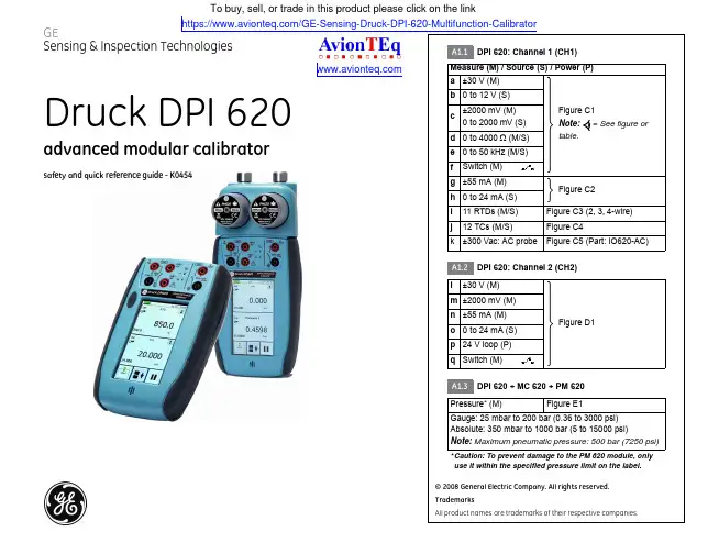
[EN] English - K0454 Issue 1 Quick Reference 1Quick ReferenceWARNING: Before you use this instrument, read and understand the “Safety” section. It is dangerous to ignore the specified warnings.Start operations (S1 to S4)S1:Install the battery. Refer to Section 5.S2:Power on/off sequenceS3:Example change of function (Voltage to Current)ON➀First display Normal outputOFF➀Press and hold PressTAPChannel Settings1324Task Settings68Task Settings5Select FunctionChannel Settings7S4:Touch-screen operations (maximise, minimise, set voltage) Menu sequenceTask*SettingsCH1CH2ChannelSettingsFunctionUnitsUtilityCaptionSelect“Function”NoneCurrentVoltage* A channel can only have one function at a time.TAPSet voltageMaximise12134Minimise*** Alternative options for step ➀TAP2 Quick Reference K0454 Issue 1 - [EN] English[EN] English - K0454 Issue 1 31OverviewThe advanced modular calibrator (AMC) is part of a set ofhand-held modules that you can quickly put together to include a wide range of calibrator functions.Advanced modular calibrator, DPI 620: This is abattery-powered instrument for electrical measure and source operations and HART® communications; see table A1(front cover). It also supplies the power and user interface functions for all the add-on modules. You can use the touch-screen to display up to six different parameters.Pressure module carrier, MC 620: Optional item. This attaches to the DPI 620 calibrator to make a fully integrated pressure indicator instrument. To measure and display pneumatic or hydraulic pressures, you can have up to two interchangeable pressure transducers at a time.Pressure modules, PM 620: Optional item. These modules attach to the pressure module carrier (MC 620) or to a pressure station (PV 62x) to give the DPI 620 calibrator the necessary pressure measurement functionality. They are fullyinterchangeable “plug and play” modules with no initial set-up or user calibration.Pressure stations, PV 62x: Optional item. To make a fully integrated pressure calibrator, you can attach the DPI 620 calibrator to one of the three pressure stations. Refer to user manual - K0457.2Standard equipmentThese items are part of the standard equipment with the DPI 620 calibrator:•DC power supply/battery charger unit •Li-Polymer battery•Set of six electrical test leads •Safety and quick reference guide •CD with the user manualDPI 620MC 620PM 620PV 62xOverview/Standard equipment3Safety Before you use the instrument, make sure that you read andunderstand all the related data. This includes: the applicablelocal safety procedures, the user manual (K0449), and theinstructions for the accessories/options/equipment you areusing it with.General warningsWARNING•It is dangerous to ignore the specified limits for the instrument or to use the instrument when it is not in its normal condition. Use the applicable protection andobey all safety precautions.•Do not use the instrument in locations with explosive gas, vapour or dust. There is a risk of an explosion.Electrical warnings •To prevent electrical shocks or damage to the instrument, do not connect more than 30V between the terminals, or between the terminals and the ground(earth).•To prevent electrical shocks, use only the GE specified AC probe (Part: IO620-AC) to measure AC voltages(maximum: 300 Vac).•This instrument uses a Lithium-Polymer (Li-Polymer) battery pack. To prevent an explosion or fire, do notshort circuit, do not disassemble, keep it safe fromdamage. For operating conditions, see Table 1.•To prevent an explosion or fire, use only the GE specified battery, power supply and battery charger. •To prevent battery leakage or heat generation, only use the battery charger and power supply in thetemperature range 0 to 40°C (32 to 104°F). Foroperating conditions, see Table 1.Pressure warnings •Some liquid and gas mixtures are dangerous. This includes mixtures that occur because ofcontamination. Make sure that the equipment is safe to use with the necessary media.•To prevent a dangerous release of pressure, isolate and bleed the system before you disconnect a pressureconnection.Continued4 Safety K0454 Issue 1 - [EN] English[EN] English - K0454 Issue 1Parts 5•To prevent a dangerous release of pressure, make sure that all the related pipes, hoses and equipment have the correct pressure rating, are safe to use and are correctly attached.CautionsTo prevent damage to the display, do not use sharp objects on the touch-screen.To prevent damage to the PM 620 module, only use it within the specified pressure limit on the label.Before you start an operation or procedure in this publication, make sure that you have the necessary skills (if necessary, with qualifications from an approved training establishment). Follow good engineering practice at all times.Marks andsymbols on the instrument4PartsRefer to the figures on the front cover (A2, B1).4.1Key to figure A2 (DPI 620 calibrator)Complies with EuropeanUnion directives Warning - refer to the manualRead the manual USB ports: Type A; Mini-type B connector Ground (Earth)ON/OFFDo not dispose of this product as household waste. Refer to “Maintenance” (Section 5.5).More marks and symbols are specified in the user manual (K0449 - Druck DPI 620Advanced modular calibrator)1.On or off button. Refer to “Quick Reference”.2. CH1Channel 1 connectors for: voltage (V); frequency (Hz);resistance (Ω); resistance temperature detectors (RTD): 3W, 4W = 3-wire, 4-wire RTD input; switch operation; current (mA+, mA-): COM = Common connectorYou can also use the GE specified AC probe (Part: IO620-AC) to measure AC voltages (maximum: 300 Vac).3.TCChannel 1 connectors for thermocouples.4.CH2Isolated channel 2 connectors for: voltage (V); current (mA+,mA-); 24V loop power supply (24Vo); switch operation6 PartsK0454 Issue 1 - [EN] English4.2Key to figure B1 (MC 620 module carrier/PM 620 module) - Optional item5.USB type A connector for connections to external peripherals (USB flash memory or optional external modules)B mini-type B connector for communication with a computer.7.+5V DC power input socket. This supply also charges the battery.8.Sealed speaker unit.9.Liquid crystal display (LCD): Colour display with touch-screen. To make a selection, lightly tap on the applicable display area.a.Battery indicatorb.Date and time10.CH1: Window for the channel 1 settings and values. c.Measure or source indicationd.Functione.Full scale (FS) rangef.Function units11.Other windows: The number of windows you see on the display is set by the number of task selections and external modules you are working with (maximum: 6).12.Tap this button to set up the Task , set up the instrument (Configure ) and to access Help (?). Refer to “Quick Reference”.Tap this button to maximise each of the available windows in sequence. Refer to “Quick Reference”.Pause (II ) or Play (X ): Tap (II ) to hold (freeze) all the data on the display. To release the display and continue, tap (X ).1.Pressure connection (G1/8 or 1/8NPT) to attach external pressure equipment.2.Pressure and electrical connections for a pressure module (PM 620). These are self-seal pressure connections.3.Two screws to attach the calibrator (DPI 620).4.Electrical connections for the calibrator (DPI 620).5.Pressure module (PM 620) with a pressure connection, reference port (a) and a label. The label includes:Pressure range . Example: 20 bar g (g: gauge; a: absolute); serial number (S/N); manufacturer : name, address, website[EN] English - K0454 Issue 1Installation 75InstallationBefore you start:•Read and understand the “Safety” section.•Do not use damaged equipment.Note: Use only original parts supplied by the manufacturer.5.1AMC batterySee figure A3 (front cover).5.2IndicatorassemblyOptional item (MC 620/PM 620). See figure B2 (front cover).5.3Electricalconnections See figure C1 to C5, and D1 (front cover).5.4External pressureconnectionsSee figure B1/E1 (front cover). Use an applicable method to seal the external pressure connections, and then tighten to the applicable torque. Maximum torque:1/8 NPT: 35 Nm (26 lbf.ft)G1/8: 25 Nm (18.4 lbf.ft)1.When the power is off, loosen the five screws (a) and remove the cover (b).If necessary, turn the instrument over and let the discharged battery drop into your hand.2.Install the new battery correctly until it is flat in the compartment.3.Re-attach the cover.1.Align the two slots (a) on the calibrator with the two posts (b) on the module carrier.2.When the posts are fully engaged in the slots, tighten the two screws until they are hand tight.3.Attach one or two PM 620 modules with the correct range and type.4.Tighten each one until it is hand tight only.5.5Maintenance Clean the case with a moist, lint-free cloth and a weakdetergent. Do not use solvents or abrasive materials.Return the instrument to the manufacturer or an approvedservice agent for all repairs. Refer to the user manual.Do not dispose of this product as household waste. Use anapproved organisation that collects and/or recycles wasteelectrical and electronic equipment. For more information,contact one of these:•our customer service department:(Contact us at )•your local government office.6SpecificationTable 1: General specificationLCD: Colour display with touch-screen-10 to 50°C (14 to 122°F)-20 to 70°C (-4 to 158°F)IP65 (DPI 620 calibrator only)0 to 90% relative humidity (RH) non-condensingDef Stan 66-31, 8.4 cat IIIElectromagnetic compatibility: BS EN 61326-1:2006Electrical - BS EN 61010:2001Pressure Equipment Directive - Class: Sound EngineeringPractice (SEP)CE MarkedLithium-Polymer battery (GE Part number: 191-356)Capacity: 5040 mAh (minimum), 5280 mAh (typical);Nominal voltage: 3.7 V.Charge temperature: 0 to 40°C (32 to 104°F)Note: When the instrument senses the temperature is outsidethis range, it stops charging.Discharge temperature: -10 to 50°C (14 to 122°F).Charge/discharge cycles: > 500 > 70% capacity8K0454 Issue 1 - [EN] EnglishMaintenance/SpecificationCustomer serviceVisit our web site: 。
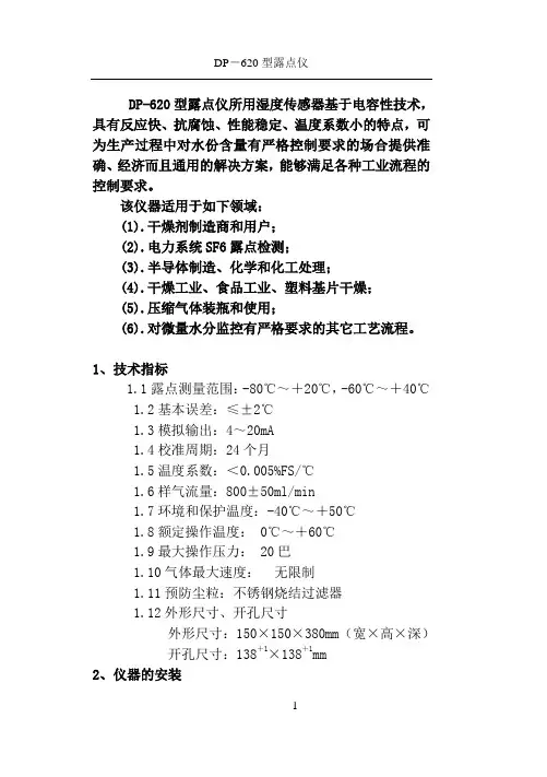
DP-620型露点仪所用湿度传感器基于电容性技术,具有反应快、抗腐蚀、性能稳定、温度系数小的特点,可为生产过程中对水份含量有严格控制要求的场合提供准确、经济而且通用的解决方案,能够满足各种工业流程的控制要求。
该仪器适用于如下领域:(1).干燥剂制造商和用户;(2).电力系统SF6露点检测;(3).半导体制造、化学和化工处理;(4).干燥工业、食品工业、塑料基片干燥;(5).压缩气体装瓶和使用;(6).对微量水分监控有严格要求的其它工艺流程。
1、技术指标1.1露点测量范围:-80℃~+20℃,-60℃~+40℃1.2基本误差:≤±2℃1.3模拟输出:4~20mA1.4校准周期:24个月1.5温度系数:<0.005%FS/℃1.6样气流量:800±50ml/min1.7环境和保护温度:-40℃~+50℃1.8额定操作温度:0℃~+60℃1.9最大操作压力: 20巴1.10气体最大速度:无限制1.11预防尘粒:不锈钢烧结过滤器1.12外形尺寸、开孔尺寸外形尺寸:150×150×380mm(宽×高×深)开孔尺寸:138+1×138+1mm2、仪器的安装仪器测量样气湿度时,传感器产生一个线性输出,对应于露点温度,标准信号输出是4~20mA。
警告:仪器被设计用在一般场合下,不能用在危险区域,所有电子连接部分应该遵守相关规定。
每个工艺和应用都是不同的,其中的差异必须被考虑到,正确的使用将导致良好和精确的测量。
2.1.仪器使用时,气体压力应低于10Bar。
2.2.不要把仪器使用在能腐蚀铝和金的气体中,这将损坏传感器。
2.3.不要把仪器使用在高温或结露的环境中,在这个环境中,传感器会损坏,而这种损坏是不包含在保修范围内的。
假如发现读数超出量程,应立即中断测量,并立即把探头放到干燥环境中。
2.4.不要把仪器使用在很脏的气体中,在恶劣环境中使用须采用过滤装置或防油系统保护探头。
仪器校准由于仪器必须与探头结合起来使用才能成为完整的探伤系统,而不同的探伤对象和环境又需要使用不同的探头,因此对探伤系统的校准是保证探伤结果真实有效的必要工作。
探伤系统的校准主要包括以下几个重要参数:1、零偏(探头延迟):由于压电晶片非常脆弱,不能直接与工件接触摩擦,因此在晶片前面都有保护晶片的保护膜或者楔块,而零偏就是指超声束在保护膜或楔块中的传播时间。
2、声速:数字式探伤仪都通过仪器测量出超声波从发射开始到反射回来的时间,然后再乘以工件内部的声速,来对回波定位,因此,精确的测量工件内部超声波传播速度,是对缺陷定位的重要参数。
3、入射点(前沿):对于斜探头而言,由于声束是倾斜入射,因此还需测量出主声轴入射到工作表面的交点到探头前端的距离,也称为前沿,测出前沿距离后,在斜探头探伤过程中测量缺陷水平距离时,就可以直接从探头前端开始定位。
4、折射角(K值):对于斜探头而言,由于声束是倾斜入射,又由于楔块与工件的声束差异较大,因此入射角与倾斜角差距较大,而斜探头对缺陷定位主要是通过声程、水平、深度三个座标的三角关系还计算得出,因此测定声束折射角对斜探头探伤定位是最重要的因素之一。
在国内由于早期都是以模拟仪器为主,因此习惯用折射角的正切值来表示,俗称K值也就是水平与深度的比值。
5、AVG曲线(DGS、DAC):AVG曲线是描述反射的距离、波幅及当量之间关系的曲线,主要用于根据缺陷反射回波的时间和波幅来确定缺陷的当量大小,是探伤时对缺陷定量的有效手段。
1选择HS620型探伤仪的接收系统状态探伤仪的接收系统所处的状态的不同组合适用于不同的检测任务。
对于特定的要求,选取某种状态组合,将起优化回波波形,改善信噪比,获得较好的近场分辨力或最佳的灵敏度余量的作用。
在仪器校准前,可选择最佳组合的接收系统,以提高仪器的校准精度。
工作方式选择:本机设有自发自收和一发一收两种工作方式,分别适用于单晶和双晶探头的使用,用户可根据所使用的探头来进行设置相应的工作方式。

LECTOR620中文操作手册安装距离和角度扫描器的安装距离是指从扫描器的窗口到条码表面的距离。
每种条码的阅读距离都不同,因此安装过程中阅读距离的确定需要查阅相关型号的技术参数。
例如,对于0.5mm分辨率的条码,其最大的视野范围是175mm×112mm(如右图),对应最大视野范围的安装高度为260mm为了避免条码表面对红光直接的反射,条码阅读器一般不采取垂直于条码表面的安装方式,应倾斜20°安装软件操作步骤(1)首先打开SOPAS 软件,一般安装SOPAS后会出现两个软件图标,一个是SOPAS,一个是SOPAS Single Device,两个是同一个软件,不同的是界面排版不同,推荐使用SOPAS Single Device界面版本(2)进入以下画面,会自动搜寻出两个设备,两个所不同是端口号,一个是以太网主口2112,一个是以太网辅口2111,推荐选择2112(3)若搜寻设备的结果如下图则说明扫描枪IP地址与电脑IP地址不一致,可修改电脑IP或扫描枪IP,注意修改时要保证扫描枪和电脑IP地址前三段一致,最后一段不同,同时保证子网掩码相同(4)修改扫描枪IP地址时,可选自动获取或者使用固定IP,推荐使用固定IP地址用于调试和通讯(5)出现选择画面,勾选尾缀为2112的扫描枪,点击继续,即可进入软件主界面。
(6)进入主界面,现处于运行模式Operation ,界面如下图:(7)调试时切换到编辑模式,点击Edit ,此时读码器连续拍照,光源一致闪烁,显示实时图像,右侧有8电脑IP 地址扫描枪IP 地址个参数栏,常用的参数栏如下:(8)第一项参数Camera & Illumination 相机和光源设定:调试要点:图像一定要清晰,根据实际情况调节曝光时间,增益和对比度获取稳定的阅读效果(9)第二项参数Codes 条码设定:本产品可同时阅读一维条码,二维PDF417码,二维码,根据所要读取的条码种类勾选相应的码制1. 相机和光源设定2. 条码种类设定3. 触发设定4. 通讯接口和信号输出设定5. 输出格式设定(10)以上图像和条码设定也可通过自学习方式完成,点击Auto Setup自动设定,如下:(11)点击后显示如下画面,首先调整Reading Distance阅读距离使图像聚焦清晰,调整Shutter time曝光时间使图像变亮,在条码的位置拖动鼠标画一个区域覆盖条码,点击继续进入自学习过程(12)学习成功后如下画面,点击继续;若自学习不成功则会显示Fail,此时可进入软件手动调整参数(13)显示如下实时阅读画面,点击结束完成自学习(14)第三项Trigger & Digital Input触发和输入信号设定,本产品触发读码器方式有很多种,常用是Sensor/Input 1,由外部接入开关量信号触发读码器开始阅读,结束阅读也有多种方式并且可以组合使用,满足任意条件均可结束阅读(15)第四项Interface & Digital Output 通讯接口和信号输出设定,常用通讯方式是串口RS232和以太网(16)串口通讯设置:点开Serial Host ,通常情况下无需修改参数,默认参数即可,但要注意波特率Baud rate 要和上位机一样触发开始串口 输出信号(17)以太网通讯设置:点开Ethernet Host,a.当需要设扫描枪为服务器端时则选择Server模式,上位机需要输入扫描枪的IP地址和端口号,其中端口号可根据需要修改,默认为2112;b.当需要设定扫描枪为客户端时则选择Client模式,此时需要输入上位机的IP地址和端口号,其中端口号可根据需要修改,默认为2112(18)扫描枪支持两路输出,以设定Output/Result 1输出信号为例,可设定成功读取Good Read或者读不到No Read时输出信号,输出电压默认为24V PNP型,也可通过反转功能变成0V有效,NPN型(19)第五项Data Processing 数据处理设定,扫描枪输出的数据格式可根据需要灵活编辑,点击Data Processing 中的Output Format1选项,默认输出格式如下图即“如果成功读取则输出条码内容,否则输出NoRead ”,可以在此处编辑,例如在条码后加入回车换行(20)数据输出格式也可通过设置向导Wizard 完成,点击Wizard 选择好所要的格式后点击继续(21)设定所需要读的码的最多和最少数量,点击继续码可在条码之间加分隔符Code Separator,如空格,斜杠等,设置完成后点击结束(23)设定完成后切换为运行模式Operation ,点击Operation 即可(24)点击参数下载和永久保存,将参数保存在扫描器中:(25)本软件自带数据接收终端,显示所读取到的数据,可用于调试串口和以太网通讯是否正常,点击数据终端Terminal ,以以太网通讯为例操作如下:若是串口则选择用户自定义连接。
多功能测试仪(TC-V2.12k)Multi-function Tester (TC-V2.12k)浩祺电子科技2015年8月Haoqi Electronic Technology Co., Ltd.August 2015目录1综述 (3)1.1本机说明 (3)1.2功能介绍 (3)2操作指引 (4)2.1按键操作定义 (4)2.2开机 (4)2.3测试晶体管 (5)2.4自动校准 (9)2.5测试稳压二极管 (10)2.6红外解码 (10)2.7关机 (10)2.8内置锂电池电压测量 (11)2.9内置锂电池充电 (11)3性能参数 (12)4常见问题 (13)5装箱单 (13)1Overview (14)1.1Introduction (14)1.2Features (14)2Operating Instructions (15)2.1Key operational definitions (15)2.2Power on (16)2.3Detect transistor (16)2.4Selftest (20)2.5Detect Zener diode (21)2.6IR decoder (21)2.7Power off (22)2.8Built-in Li-ion Battery voltage measurement (22)2.9Charging the Battery (23)3Performance Parameters (23)4FAQ (24)5Packing List (24)多功能测试仪(TC-V2.12k)1综述1.1 本机说明① - 160x128 TFT显示屏② - 多功能按键③ - 晶体管测试区④ - 稳压二极管测试区⑤ - 红外接收窗口⑥ - Micro USB充电接口⑦ - 充电指示灯1.2 功能介绍TC-V2.12k是采用TFT图形显示的多功能测试仪。
●晶体管测试仪-自动测量NPN和PNP晶体管、N沟道和P沟道场效应管、二极管(含双二极管)、电阻(含电位器)、电感、电容、可控硅、电池(0.1-4.5V)等元器件-自动测量稳压二极管(0.01-30V)-自动校准功能●红外解码器-支持日立公司编码-红外波形显示-红外接收指示●其他-测量结果采用TFT图形显示-一键操作-自动关机(关机时长可设置)-内置大容量可充电锂电池-锂电池电压检测-支持中英文双语警告:内置锂电池,严禁将测试仪浸入水中、严禁靠近热高温源!警告:为了您的人身安全,请严格遵守锂电池使用规范和注意事项!2操作指引2.1 按键操作定义多功能按键有两种操作:●短按:按下按键不短于10毫秒且在1.5秒内松开按键●长按:按下按键1.5秒以上2.2 开机关机状态下短按多功能按键,测试仪开机并自动进行测量。
HS620型数字式超声波探伤仪的基本操作一、横波斜探头调校与应用对于横波斜探头接触法检测而言,在执行任何检测任务前做距离校准是必不可少的程序。
商用斜探头的类型众多,结构尺寸各异,对不同的检测对象要求的K 值不同,因而在楔块中的声程的大小也不一样,即对每个横波斜探头都要测量它的入射点,确定零偏值。
斜探头在使用过程中随着楔块的磨损,经过一段使用后也要重新校准。
1. 斜探头入射零点快捷调校模式下面以CSK-ⅠA标准试块为例如图所示,介绍斜探头的快捷调校步骤。
1) 将探头与仪器连接好,如上图所示将探头放置在CSK -ⅠA试块上。
2) 按通道键,再按键,选择任意斜/表探头通道,按键,进入参数列表,按键将光标移动到试块选择栏,把试块选择栏改为CSK-ⅠA试块,按键,退出参数列表。
3) 进行自动校准(1)按热键进入自动校准功能,屏幕右上角显示“自动校准”字样。
(2)将斜探头放置在CSK-ⅠA试块的R50和R100的圆心处,来回移动探头,直到R50和R100的反射回波同时出现在波形显示区内。
此时首先寻找R100弧面最高反射回波,(如果波形不在屏幕内时可按零偏对应的键,按武汉中科创新技术股份有限公司键将波形移动到屏幕内),当回波高度超出满刻度时或低于20%时可按键,反复上述直至确定最高反射波80%,此时看R50弧面的回波是否在屏幕上高于20%。
若低于此高度,可将探头平行地向R50的弧面横向移动,直至R50、R100的两弧面回波高度均在满刻度的20%以上。
(3)再按键仪器开始自动校准,此时固定探头不动。
校准完之后,屏幕下方显示:“自动校准完毕!”(4)完毕后屏幕上显示“请用钢尺测前沿:0.0”,固定探头不动,用钢尺测量探头前端到CSK-1A试块R100端边的距离X,然后用100-X所得到的数值就是探头的前沿值。
如图所示:用键将探头前沿值改为实测数值后,按键,前沿修改完毕,此时前沿值即自动存入仪器中。
2. K值测量1)在试块选择栏选择为CSK-ⅠA试块时,在自动调校完毕后,K值对应的键,仪器会自动进入K值测试状态,屏幕下方显示“进入K值测试”,且默认CSK-ⅠA试块上深度30mm的Φ50孔为K值测试孔,闸门自动锁定Φ50孔波位置,如图所示:2) 将探头对准Φ50孔方向,前后移动探头找出孔波最高回波,按键,屏幕下方显示“所测K值为:1.98”。
“汉威” HS620仪器与探头综合性能测试方法超声波探伤系统工作性能测试操作、直探头性能测试按增益键,再按键将增益提高,只到屏幕上的电噪声信号平均波幅到 10%FS 为止,4) 将探头放在灵敏度试块上(①2X 200伽),移动探头找出①2孔的最高回波,按增益键调 整波形到50%FSH 并记录下当前衰减器增益读数S 。
5) 灵敏度余量 △ S = S 0 - S i 将计算出的数值填写在记录纸上。
1、 1)灵敏度余量测试方法:开机后按L 日键,再按匚二I I 选择一个“直探头”通道。
2)并记录下当前衰减器的增益读数 S 0, 3)按范围对应的键,再按’“二I 键,将满屏范围调至大于225mm2、 1) 2律料曹■律增益IV.DD <11+ B , 0X :* ■■■ 4 託□ • 1 ”一•羽甲i 445 * 乳 0 135. 0 HD.* £a as‘直探头水平线性测试方法键,再按;二I 选择一个“直探头”通道。
将探头置于CSK-IA 试块上厚度25m m 的平面上,找出第一次回波(B1 )。
开机后按按范围对应键两次切换到平移状态,再按 键切换到范围状态,再按:二I 齐第2、4、& 8格,如果对不齐,则按调校键,再按零偏对应键,然后按方向键使之对齐, 并记录下零偏调节的数值,(例如:B2没对齐第2格,调节零偏0.6uS 以后对齐则偏差值为 0.6 )取最大偏差值Amax 代入下式计算:△ L= | Amax|%3) I 键使B6对齐水平满刻度,分别观察 B2、B3、B4 B5是否对a|键,将B1调至0刻度,然后按平移对应“汉威” HS620仪器与探头综合性能测试方法3、垂直线性测试方法:1) 开机后按匕壬1键,再按匚二I 选择一个“直探头”通道。
2) 按范围对应的键,再按 '二1键,将满屏范围调至大于225mm将直探头与仪器连接,并将探头放在灵敏度试块上( ①2X 200伽),移动探头找出①2孔 4) 按增益键,将增益步进调整为 2dB5) 按'二键,进行2dB 一次的衰减,并将每次的波幅读数记录下来,与理论值对比。
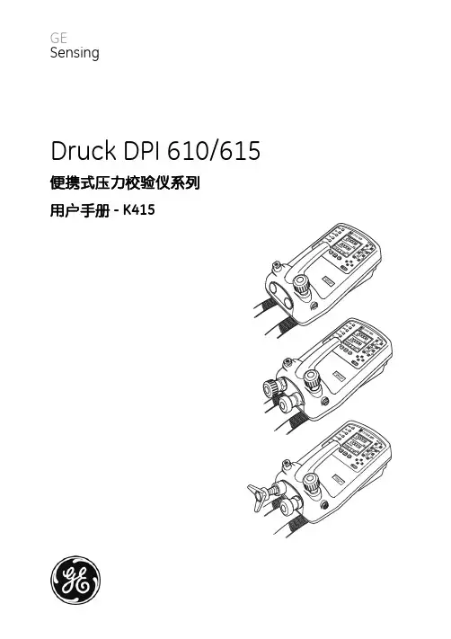
GEDPI 611Druck DPI 610/615很多领域甚至成为了德鲁克(Druck)的一个名片。
DPI 611 手持式压力校验仪DPI 611 是DPI 600 家族里的第四代产品,Druck从1984年开始推出DPI600系列产品后,DPI600系列产品一直是一体式压力校验仪的领导者,通过革命性的将造压功能,信号测量功能集成到一个单一仪器中,DPI 600 一直是工业压力校准的一个标准,在基于30多年的压力测量和校准经验的积累以及技术能力的储备,DPI 611将为压力校准提供更优的便捷性和可靠性,技术指标提升一倍,而产品尺寸将会缩小一半左右。
• 比DPI 610的尺寸小50%, 重量轻 33%• 打压到 2 MPa 的时间将小于 30秒 • 能产生低于 95% 的真空• 压力测量的准确度提升两倍左右• 电信号测量的精度提升三倍左右• 简洁的触摸操作屏,功能选项面板,快速任务选项栏以及自定义的任务收藏夹• 任何应用任务都可以通过三次点击选中• 实时误差(合格/超差)显示,结果文档处理功能先进的工艺流程和精密加工先进的工艺流程和精密的加工保障了仪器的特优性能DPI 611压力系统创新的高效造压能力以及精密的压力调节都是通过严格的选料以及特优的公差配合来实现的。
外壳材料的精挑细选以及精密的开模保证DPI 611非常坚固并满足全天候的使用要求。
采用最新的模拟和数字微电子技术来实现高精度的电气测量以及独特的简易使用接口。
先进的工艺以及精密加工决定产品的品质和性能测量的准确度包括了一年的稳定性、DPI 611 mA造压DPI 611 可以产生从95% 真空至2 MPa 的气体压力。
通过一个简单的切换阀就可以实现真空到压力的切换,通过仪器自带的气泵的几下打压就可以达到要产生的压力。
微调功能通过内置的精密容积调节阀来实现。
反行程的点通过精密的泄压阀来实现。
∙ 重新设计的机械结构使得仪器的整体性能得到了很大提升,现在单手握住仪器就可以产生2 MPa 的压力。