MC5多功能校验仪
- 格式:pdf
- 大小:203.67 KB
- 文档页数:3


PMC-53M多功能电力仪表(LED版)使用手册(2012.05.V2.0版)目录一、概述 (1)二、技术参数 (1)2.1辅助电源 (2)2.2输入信号 (2)三、编程和使用 (2)3.1按键定义 (2)3.2测量显示……………………………………………………………………………2-33.3页面显示示意图…………………………………………………………………3-73.4编程操作 (8)3.5菜单组织结构图 (9)3.6编程菜单结构图 (10)调试举例图…………………………………………………………………11-12四、数字通讯 (13)4.1报文格式指令 (15)4.2脉冲输出 (16)MODBUS-RTU通讯地址信息表......................................................17-20五、接线图 (21)42方型接线图 (21)96方型接线图 (22)六、常见问题及解决方案 (23)PMC-53M多功能电力仪表--用户手册一、概述PMC-53M多功能电力仪表是一种具有可编程测量、显示、数字通讯和电能脉冲变送输出等功能的多功能电力仪表,能够完成电量测量、电能计量、数据显示、采集及传输,可广泛应用变电站自动化,配电自动化、智能建筑、企业内部的电能测量、管理、考核。
测量精度为0.5级、实现LED现场显示和远程RS-485数字通讯接口,采用MODBUS-RTU通讯协议外形代号名称测量显示标配功能42方形多功能电力仪表三相:U、I、P、Q、EP+、EP-、EQ+、EQ-、SP、F、PF或部分参数LED分页显示RS485通讯、电能脉冲输出96方形二、技术参数性能参数输入测量显示网络三相三线、三相四线电压额定值AC25~500v过负荷持续:1.2倍瞬时:10倍/10s功耗<1VA(每相)阻抗>500kΩ精度RMS测量,精度等级0.5电流额定值AC0~5A过负荷持续:1.2倍瞬时:10倍/10s功耗<0.4VA(每相)阻抗<2mΩ精度RMS测量,精度等级0.5频率45~65Hz功率视在功率,有功精度0.5级,无功精度1.0级电能四象限计量,有功精度1.0级,无功精度1.5级谐波总谐波含量2-31次电源工作范围AC/DC85~270V 功耗≤5VA输出数字接口RS-485、MODBUS-RTU协议脉冲输出2路电能脉冲输出,脉冲常数:5000imp/h环境工作环境-10~55℃储存环境-20~75℃安全耐压输入/电源>2kV,输入/输出>2kV,电源/输出>1kV绝缘输入、输出、电源对机壳>50MΩ电能测量范围有功无功电度测量范围0~99999999Mwh,超过此数值电度从0开始计数2.1辅助电源:PMC-53M多功能电力仪表具备通用的(AC/DC)电源输入接口,若不作特殊声明,提供的是AC/DC85~270V电源接口的标准产品,请保证所提供的电源适用于该系列的产品,以防止损坏产品。
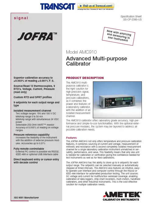
Specification Sheet SS-CP-2385-USPRODUCT DESCRIPTIONThe AMC910 multi-purpose calibrator is the right solution for high precision signal, temperature, and pressure calibrations, as it combines the power and features of a laboratory calibrator, with the addition of an isolated measurement channel.The AMC910 calibrator offers laboratory grade accuracy, high per-formance and simple-to-use functionalities. With the optional exter-nal pressure modules, the system may be taylored to address all possible calibration needs.FeaturesThe JOFRA AMC910 not only offers temperature and pressure calibration features, it combines sourcing of current and voltage, measurement of millivolts and resistance with a second completely isolated measurement channel for a single laboratory calibration instrument unmatched in ver-satility, performance, and value. This flexibility means that only one unit is needed for calibration or verification giving the confidence needed for test instruments as well as for field calibrations.The JOFRA AMC910 has the ability to store up to 9 setpoints for each output range. The setpoints can be selected manually or automatically stepped at timed intervals. The AMC910 also features an intuitive, easy-to-operate user interface and computer control through the RS232 or IEEE-488 interface for automated production testing. The unit sources DC voltage and current for multifunction workload coverage, enabling calibration of data loggers, strip chart recorders, multi-meters, handheld calibrators, and other industrial instruments. This is the cost-effective solution for multiple calibration needs.Model AMC910Advanced Multi-purpose CalibratorN ow wi t h s ou r c i n ga n d me a s u r i n g i no n e i ns t r u m e n t2Direct keyboard entry (1)The JOFRA AMC910 provides simple, front-panel entry of mode,range, and value. Using direct keyboard entry (1), the exact valuedesired is entered using the numeric keys, and the ENTER keyis pressed to set the output to that value. Whichever way youchoose, setup is simple and fast. In the voltage output mode, theJOFRA AMC910 auto-ranges on the entered value for maximumaccuracy at all times.Curser entry (2)Using cursor entry (2), the LEFT/RIGHT arrow keys are used tomove the cursor under the digit in the display to be changed. TheUP/DOWN arrow keys increment/decrement the value at the cur-sor position.Choose the mode you want (3)Voltage ModeThe JOFRA AMC910 offers four precision voltage output ranges(100mV, 1V, 10V, and 100V) all with ±0.003% of reading ±0.001%F. S. accuracy. These ranges are ideal for calibrating a broadrange of DC voltage instrumentation. Additionally all voltageoutputs settle to full specification in less than 200ms making theJOFRA AMC910 ideal for automated calibration systems.An automatic stand-by mode (3) assures that output voltagesabove 30VDC must be acknowledged by the operator before thevoltage appears at the output jacks. The stand-by mode is alsotriggered if the output current compliance is exceeded, therebyprotecting the device under calibration.Current ModeThe JOFRA AMC910 features a precision current output range(100mA) that offers 0.01% accuracy, which is ideal for calibratingprocess instrumentation especially 4 to 20mA equipment. Witha full 12 volts of compliance at 100mA virtually any precision DCcurrent measuring device can be calibrated using the JOFRAAMC910. Like the voltage ranges the current range offers quicksettling time and an operate/stand-by mode.Thermocouple ModeThe JOFRA AMC910 can read and source any of 11 typesof thermocouples. Its T/C input and output is Cold JunctionCompensated, using an ultra-stable PT-1000 sensor.RTD ModeThe JOFRA AMC910 can read and source 9 RTD types as well asYSI-400 and Ohms for non-standard curves. Probe coefficients (A,B, C, and R0) can be entered directly, with storage for up to fivecustom curves and one SPRT curve. The performance of the JOFRAAMC910 in the RTD mode compares to dedicated RTD measure-ment instruments. Unlike low-cost, less accurate RTD instruments,the display in the JOFRA AMC910 is always active, reading to threedecimal places, using polynomial averaging to extract a high accu-racy signal. The result is a very high accuracy reading.Pressure ModeSignal calibration capabilities of the JOFRA AMC910 include, cur-rent, voltage and resistance. In temperature mode, the unit can readand source any of 11 types of thermocouples and 9 RTD types aswell as YSI-400 and Ohms for non-standard curves. In pressuremode, the instrument operates with all JOFRA APM modules andcovers pressure ranges from vacuum to 700 bar / 10,000 psi, select-able through more than 60 different pressure modules, representingvacuum, absolute, gauge and compound pressure types as well asSetpoint Control (4 and SPT)A SHIFT key (4) provides easy accessto the setpoint controls of the JOFRAAMC910. Up to nine setpoints canbe defined for each output mode andeach thermocouple and RTD type.Setpoints are recalled individually atthe touch of three buttons, SHIFT (4),SETPOINT (SPT) button and then thecorresponding numeric keys 1-9. Anynumber of sequential setpoints canbe stepped through automatically,with complete control of dwell time.Either way, for rapid setup of repeat-able tests, no other instrument comesclose to the JOFRA AMC910.Remote Control (4)All of the JOFRA AMC910 operating functions can be accessedvia RS232, IEEE-488 or optional USB interface cable using astandard PC running Windows® HyperTerminal or other soft-ware using an ASCII protocol. Custom control programs maybe written using programming software such as C++. Switchingbetween LOCAL and REMOTE is as simple as touching theSHIFT (4) and LOCAL buttons.Rock-Solid StabilityThe accuracy of the JOFRA AMC910 is specified for both 90-dayand one-year intervals. Manual zero calibrations can be made onall T/C and pressure functions to eliminate offsets.Flexible Output (5, 6 and 7)Five-way copper alloy binding posts (5) provide a wide range ofconnection options. A standard pressure module connector isprovided (6), as is the CJC T/C mini-jack (7).Isolated Measurement Channel (8 and 9)The JOFRA AMC910 features a fully isolated measurement chan-nel which allows the user to calibrate process transmitters andsignal isolators. In reality it’s like having two instruments in one!This channel also incorporates a 24 volt loop power supply topower 2-wire transmitters and a HART interface resistor enablingdirect connection to HART communicators. Key features are:Two voltage ranges 10V and 100V DCMilliamp range 0 to 50mAMilliamp range with simultaneous 24 volt power (0 to 24ma)Selectable 250 ohm HART resistorAccuracy of 0.005% of reading on all ranges•••••3SPECIFICATIONS AMC910(1 year at 23°C ±5°C; % of reading, unless otherwise noted)Output VoltageRange..0 to 100.000 mV, 0 to 1.00000 V, 0 to 10.0000 V, 0 to 100.000 V Resolution0 to 100 mV Range ..................................................................1 μV 0 to 1 V Range .......................................................................10 μV 0 to 10 V Range ...................................................................100 μV 0 to 100 V Range ....................................................................1 mV Accuracy (% of reading)0 to 100 mV Range ................................±0.003% (30ppm) ± 3 μV 0 to 1 V Range .....................................±0.003% (30ppm) ± 10 μV 0 to 10 V Range .................................±0.003% (30ppm) ± 100 μV 0 to 100 V Range ..................................±0.003% (30ppm) ± 1 mV Maximum Burden (~ 1 Ohm output impedance)0 to 100 mV Range ...............................................................10 mA 0 to 1 V Range ......................................................................10 mA 0 to 10 V Range ....................................................................10 mA 0 to 100 V Range ....................................................................1 mA Output CurrentRange ...................................................................0 to 100.000 mA Resolution ................................................................................1 μA Accuracy (% of reading) .................................± 0.005% ± 1 Count Maximum Burden .....................................................................10 V ThermocouplesOutputTypes ....................................J, K, T, E, R, S, N, B, L, U, C, BP, XK Range .........................................................................................mV Resolution ........................................................................0.1 °C/°F Accuracy ....................................................0.14 °C; Type J, typical InputTypes ....................................J, K, T, E, R, S, N, B, L, U, C, BP, XK Range .........................................................................................mV Resolution ......................................................................0.01 °C/°F Accuracy ....................................................0.14 °C; Type J, typical RTDOutput Range ....................................Pt385 (100, 200, 500, 1000), Pt392, ................................................Pt3916 (JIS), Ni120, Cu 10, YS I400Resolution .......................................0.01 °C/°F; Pt385-100, typical Accuracy ..............................±0.05°C / 0.09°F; Pt385-100, typical Input (All RTD inputs are 4 wire)Range ....................................Pt385 (100, 200, 500, 1000), Pt392, ........................PT3916 (JIS), Ni120, Cu10, YSI400, 25 Ohm SPRT Resolution ......................................0.001°C/°F; Pt385-100, typical Accuracy ..............................±0.02°C / 0.04°F; Pt385-100, typical OhmsOutput Range ........................................................................5 to 4000.0 ΩResolution .....................5 to 400.00 Ω .............................0.001 Ω........................................5 to 4000.0 Ω ...............................0.01 ΩAccuracy ........................5 to 400.00 Ω .............................±0.05 Ω........................................5 to 4000.0 Ω ...............................±0.3 ΩInput (4 wire connection)Range ......................................................................0 to 4000.00 ΩResolution .....................0 to 400.00 Ω ...............................0.001 Ω ........................................0 to 4000.0 Ω ...............................0.01 ΩAccuracy ........................0 to 400.00 Ω .............40 PPM ±0.002 Ω........................................0 to 4000.00 Ω .............40 PPM ±0.02 ΩPressureRange .......................................................0 to 700 bar / 10,000 psi Compatibility ...........................All JOFRA APM pressure moduels Isolated Measurement ChannelRange ...............................................................................Accuracy 0-10.0000V .........................................................±0.005% ± 0.2mV 0-100.000V .........................................................±0.005% ± 2.0mV 0-52.0000mA ...........................................................±0.01% ± 1μA Loop power: .................................................................24 V ± 10%HART™ resistor: ...........................................................250Ω ± 3%Maximum current: .................................................................24 mA StabilityWarm-up Time .................................30 minutes to rated accuracy Temp. coefficient (t<18°C/t>28°C) ........10% of accuracy spec/°C Temp. coefficient (t<64°C/t>82°C) ..........5% of accuracy spec/°F EnvironmentalOperating Temperature ..............................0 to 50°C / 32 to 122°F Storage Temperature ...............................-20 to 70°C / -4 to 158°F Operating humidity ........................................< 80% to 30°C / 86°F ......................................................................< 70% to 40°C / 104°F ......................................................................< 40% to 50°C / 122°F Storage humidity ........................................<95%, non-condensing Power RequirementsVoltage Range .........................................................90 to 240 VAC ....................................................................................... Max. 15 VA MechanicalDimensions (h x w x d): ..............17.7 cm x 48.26 cm x 27.96 cm / .............................................................................5 in x 19 in x 11 in Weight ...................................................................4.8 kg / 10.5 lbs Display 2 Large character 16 by 2 line alphanumeric backlit LCDsOrder No.Description Base model numberAMC910AMC910 Advanced Multi-purpose Calibrator Power supply115 115 VAC, 50/60 Hz 220 230 VAC, 50/60 Hz Mains power cable type A EUROPEAN, 230 V B USA/CANADA, 115 V C UK, 240 VD SOUTH AFRICA, 220 VE ITALY, 220F AUSTRALIA, 240 VG DENMARK, 230 VH SWITZERLAND, 220 VI ISRAEL, 230 VCertificateG NIST traceable certificate (standard)HAccredited certificateAMC910115BG Sample order numberJOFRA AMC910 for 115 VAC with NIST traceablecertificate.ORDERING INFORMATIONAMETEK Calibration Instrumentsis one of the world’s leading manufacturers anddevelopers of calibration instruments fortemperature, pressure and process signalsas well as for temperature sensors both froma commercial and a technological point of view.JOFRA Temperature InstrumentsPortable precision thermometers. Dry-block andliquid bath calibrators: 4 series, with more than25 models and temperature ranges from-90° to 1205°C / -130° to 2200°F. All featuring speed,portability, accuracy and advanced documentingfunctions with JOFRACAL calibration software.JOFRA Pressure InstrumentsConvenient electronic systems ranging from-1 to 1000 bar (25 inHg to 14,500 psi) -multiple choices of pressure ranges, pumps andaccuracies, fully temperature-compensatedfor problem-free and accurate field use.JOFRA Signal InstrumentsProcess signal measurement and simulation foreasy control loop calibration and measurementtasks - from handheld field instruments tolaboratory reference level bench top instruments.JOFRA / JF Marine InstrumentsA complete range of calibration equipmentfor temperature, pressure and signal,approved for marine use.FP Temperature SensorsA complete range of temperature sensorsfor industrial and marine use.M&G Pressure TestersPneumatic floating-ball or hydraulic piston deadweight testers with accuracies to 0.015% of reading.M&G PumpsPressure generators from small pneumatic“bicycle” style pumps to hydraulic pumpsgenerating up to 1,000 bar (15,000 psi)....because calibration isa matter of confidenceJOFRA AMC910 calibratorInstruction manualAC line cordThermocouple shorting jumperNIST traceable certificate•••••Information in this document is subject to change without notice.©2007, by AMETEK, Inc. All rights reserved.Pub code SS-CP-2385-US Issue 0901JOFRA APM PRESSURE MODULESTo get an ideal reference system, JOFRAoffers a range of reference sensors. All JOFRASuperior Temperature Standard sensors areeconomical and offer fast response times, lowimmersion depths, compact physical sizes, andspecified low drift rates: even at high tempera-tures. These are all important considerationswhen selecting a reference sensor.Please find more information in accessory sheet AS-CP-2210, which maybe found at JOFRA STS REFERENCE SENSORSThe APM series of pressure modules by JOFRA arecompatible with the AMC900, AMC910, ASC300or APC calibrators. The JOFRA APM external pres-sure modules includes more than 60 models avail-able with gauge, absolute, differential, and vacuumpressure references and in metric and imperialengineering units. The modules are engineered forin-plant, field, or laboratory use. They are ready-to-use with the JOFRA AMC910 and the protocolallows for immediate recognition and use of themodule once plugged into the calibrator.Please find more information in specification sheet SS-CP-2190, whichmay be found at STANDARD DELIVERYACCESSORIESPart No. Description121985 Extension cable for Pt100 sensor, length 5.0 m121983 Extension cable for Type K - 5 m122523 Extension cable for Type N - 5 m120519 Thermocouple Male Plug - Type Cu-Cu - White120518 Thermocouple Male Plug - Type R / S - Green120517 Thermocouple Male Plug - Type K - Yellow120516 Thermocouple Male Plug - Type J - Black120515 Thermocouple Male Plug - Type T - Blue120514 Thermocouple Male Plug - Type N - Orange2206011 Thermocouple plug + K wire + alligator2206012 Thermocouple plug + T wire + alligator126812 Cable for USB to serial105366 Cable for RS232104203 Test lead set。
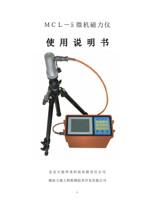
MCL-5微机磁力仪使用说明书北京大地华龙科技有限责任公司廊坊大地工程检测技术开发有限公司感谢您使用MCL-5微机磁力仪MCL-5微机磁力仪是我公司在MCL-1A型数字磁力仪和MCL-2型数字磁力仪基础上结合磁三分量的原理研制成功的“总场磁力仪”,它是根据磁通门原理利用计算机智能控制的新型磁力仪,主要用于铁矿勘察。
可测量磁场总场强度T或者垂直分量Z。
由于该磁力仪操作十分简单,几分钟即能学会使用,大屏幕液晶可直接显示被测的磁场强度nT(伽码),同时显示温度,日期,电量(仪器电池),特别适合于初学者使用。
由于该磁力仪内置计算机,具有自动线性校正,自动温度校正,24位高精度A/D转换器,可测量高达8万纳特强磁场,大屏幕显示器可显示磁场强度曲线,方便直观,与电脑连接可进一步作数据处理和解释推断,故该磁力仪同样适用于专业物探、地质人员使用,是一种操作简便,具有较高分辨率和较高精度的磁力仪,性价比很高。
目录§1、仪器的主要功能与用途 (1)§2、仪器的组成及主要技术指标 (1)§3、仪器的操作菜单及键盘说明 (2)§ (3)§ (3)§ (4)§ (5)§ (5)§4、仪器使用方法 (6)§4.1 总场测量 (7)§4.2垂直场测量 (8)§5、数据传输及保存 (9)§6、仪器的仪器的维护与保养 (11)§1、仪器的主要功能与用途该仪器主要用于在地面上的铁矿勘察。
具有如下功能:1.多参数测量:测量磁场的总场强度T或者磁场垂直分量Z。
2.直接显示异常值:在测量有基点值的前提下,直接显示总场的异常值或者垂直分量的异常值。
3.自动生成曲线图:测线磁测完成后,可显示(总场的异常值)或者(垂直分量的异常值)曲线图,用于指示矿体位置。
4.数据存储:自动存储基点值和测点的磁测数据,最大存储5000个测点,可通过数据传输接口连接计算机,所有数据可传输到计算机内做进一步分析和永久保存。
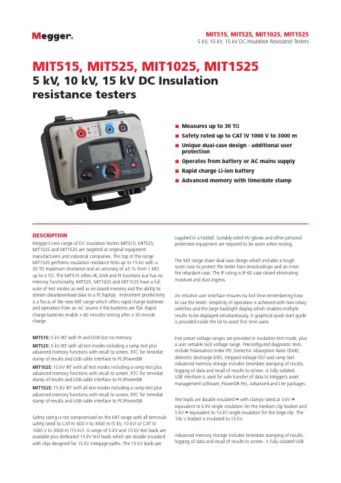
DESCRIPTIONMegger’s new range of DC insulation testers MIT515, MIT525,MIT1025 and MIT1525 are targeted at original equipment manufacturers and industrial companies. The top of the rangeMIT1525 performs insulation resistance tests up to 15 kV with a30 TΩ maximum resistance and an accuracy of ±5 % from 1 MΩup to 3 TΩ. The MIT515 offers IR, DAR and PI functions but has no memory functionality. MIT525, MIT1025 and MIT1525 have a full suite of test modes as well as on-board memory and the ability to stream data/download data to a PC/laptop. Instrument productivity is a focus of the new MIT range which offers rapid charge batteries and operation from an AC source if the batteries are flat. Rapid charge batteries enable > 60 minutes testing after a 30 minute charge.MIT515: 5 kV IRT with PI and DAR but no memoryMIT525: 5 kV IRT with all test modes including a ramp test plus advanced memory functions with recall to screen, RTC for time/dat stamp of results and USB cable interface to PC/PowerDBMIT1025: 10 kV IRT with all test modes including a ramp test plus advanced memory functions with recall to screen, RTC for time/dat stamp of results and USB cable interface to PC/PowerDBMIT1525: 15 kV IRT with all test modes including a ramp test plus advanced memory functions with recall to screen, RTC for time/dat stamp of results and USB cable interface to PC/PowerDBSafety rating is not compromised on the MIT range with all terminals safety rated to CAT IV 600 V to 3000 m (5 kV, 10 kV) or CAT IV 1000 V to 3000 m (15 kV). A range of 5 kV and 10 kV test leads are available plus dedicated 15 kV test leads which are double insulated with clips designed for 15 kV creepage paths. The 15 kV leads are supplied in a holdall. Suitably rated HV gloves and other personal protection equipment are required to be worn when testing.The MIT range share dual case design which includes a tough outer case to protect the tester from knocks/drops and an inner fire retardant case. The IP rating is IP 65 case closed eliminating moisture and dust ingress.An intuitive user interface ensures no lost time remembering how to use the tester. Simplicity of operation is achieved with two rotary switches and the large backlight display which enables multiple results to be displayed simultaneously. A graphical quick start guide is provided inside the lid to assist first time users.Five preset voltage ranges are provided in insulation test mode, plus a user settable lock voltage range. Preconfigured diagnostic tests include Polarisation Index (PI), Dielectric Absorption Ratio (DAR), dielectric discharge (DD), Stepped Voltage (SV) and ramp test. Advanced memory storage includes time/date stamping of results, logging of data and recall of results to screen. A fully isolatedUSB interface is used for safe transfer of data to Megger’s asset management software; PowerDB Pro, Advanced and Lite packages.Test leads are double insulated t with clamps rated at 3 kV t equivalent to 6 kV single insulation for the medium clip leadset and 5 kV t equivalent to 10 kV single insulation for the large clip. The 15k V leadset is insulated to 15 kV.Advanced memory storage includes time/date stamping of results, logging of data and recall of results to screen. A fully isolated USBMIT515, MIT525, MIT1025, MIT15255 kV, 10 kV, 15 kV DC Insulation Resistance TestersMIT515, MIT525, MIT1025, MIT15255 kV, 10 kV, 15 kV DC Insulationresistance testers■■Measures up to 30 TΩ■■Safety rated up to CAT IV 1000 V to 3000 m■■Unique dual-case design - additional userprotection■■Operates from battery or AC mains supply■■Rapid charge Li-ion battery■■Advanced memory with time/date stampdevice interface (type B) is used for safe transfer of data to Megger’s PowerDB / Pro, Advanced and Lite asset management software. (MIT525, MIT1025 nd MIT1525 only)APPLICATIONThe Insulation Resistance (IR) test is a quantitative test which indicates the effectiveness of a product’s electrical insulation. Applications include cables, transformers, motors/generators, circuit breakers and bushings. Common insulation tests are the “spot test”, a 1 minute IR test and a 10 minute Polarisation Index (PI) test, where PI is the ratio R10min / R1min and is temperature independent.FEATURES AND BENEFITS■■Insulation resistance up to 30 TΩ @ 15 kV , 20 TΩ @ 10kV , 10 TΩ@ 5 kV■■IR, Timed IR, DAR, PI, DD, SV and ramp diagnostic tests ■■High current – 3 mA short circuit current■■High noise immunity – 3 mA (5 kV and 10 kV) 6 mA (15 kV) ofnoise rejection■■Li-ion battery – up to 6 hrs continuous testing @ 5 kV with a100M load, battery meets IEC 2133■■Safety rating: CAT IV 600 V to 3000 m (5 kV , 10 kV) CAT IV 1000V to 3000 m (15 kV)■■Large LCD display with backlight■■Dedicated voltmeter function (30 V to 660 V)■■Advanced memory, on screen recall and real time clock for date/time stamped results (MIT525, MIT1025 and MIT1525 only)■■Download of on-board results via USB interface (MIT525,MIT1025 and MIT1525 only)■■Recorded temperature (measured by independent instruments)can be saved with test result (MIT525, MIT1025 and MIT1525 only)■■PowerDB Lite asset management software supplied (MIT525,MIT1025 and MIT1525 only)■■MIT515, MIT525 and MIT1025 safety rated at CAT IV 600 V(maintained to 3000 m altitude)■■MIT1525 safety rated at CAT IV 1000 V (maintained to 3000 maltitude)SPECIFICATIONSAC voltage (auto-ranging)5 kV , 10 kV: 90-264 V rms, 47- 63 Hz 100 VA15 kV: 90-264 V rms, 47- 63 Hz 200 VABattery charge time 2.5 hours deep discharge, 2 hours normal dischargeBattery life11.1 V , 5.2Ah Li-ion batteries, meet IEC 62133:2003, MIT1525 has 2 battery packsBattery life MIT515, MIT525: 6 hours (typical) continuous testing at 5 kV with a 100 MΩ load Battery life MIT1025: 4.5 hours (typical) continuoust esting at 10 kV with a 100 MΩ load Battery life MIT1525: 4.5 hours (typical) continuous t esting at 15 kV with a 100 MΩ load Test voltageMIT515, MIT525:250 V , 500 V , 1000 V , 2500 V , 5000 V , V L MIT1025:500 V , 1000 V , 2500 V , 5000 V , 10000 V , V L MIT1525:1000 V , 2500 V , 5000 V , 10000 V , 15000 V , V L Lock test voltage100 V L to 1 kV in 10 V steps, 1 kV to 5 kV in 25 V steps, 5 kV to 15 kV in 25 V steps Test voltage accuracy+4%, -0%, ±10 V nominal test voltage at 1 GΩ load (0°C to 30°C)Resistance range10 kΩ to 15 TΩ @ 5 kV , 10 kΩ to 20 TΩ @ 10 kV , 10 kΩ to 30 TΩ @ 15 kVAccuracyMIT515, MIT525 accuracy (23 °C) 5000 V 2500 V 1000 V 500 V250 V±5% from 1MΩ to 1 TΩ 500 GΩ 200 GΩ 100 GΩ 50 GΩ ±20% from 1MΩ to 10 TΩ 5 TΩ 2 TΩ 1 TΩ 500 GΩ MIT1025 accuracy (23 ºC) 10 kV 5000 V 2500 V 1000 V500 V±5% from 1MΩ to 2 TΩ 1 TΩ 500 GΩ 200 GΩ 100 GΩ±20% from 1MΩ to 20 TΩ 10 TΩ 5 TΩ 2 TΩ1 TΩMIT1525 accuracy (23 ºC) 15 kV 10 kV 5000 V 2500 V 1000 V ±5% from 1MΩ to 3 TΩ 2 TΩ 1 TΩ 500 GΩ 200 GΩ±20% from 1MΩ to 30 TΩ20 TΩ10 TΩ5 TΩ2 TΩGuard terminal performanceGuards out parallel leakageresistance down to 250 kΩ with a maximum additional resistance error of 1% with a 100 MΩ load DisplayAnalogue : 100 kΩ to 10 TΩDigital: 10 kΩ to max a above Short circuit/charge current 3 mA @ 5 kV , 10 kV , 15 kV Insulation testAlarm: 100 kΩ to 10 GΩTEST LEADS SUPPLIEDThe MIT515. MIT525, MIT1025 and the MIT1525 are all supplied with test leads that are compliant with the requirements ofIEC61010-031:2008. The 5 kV models are supplied with one 3m lead-set with medium sized clips. The 10 kV models are supplied with two 3m lead-sets, one with medium sized clips and the other with large clips with insulation suited to 10 kV use and the 15 kV models supplied with a 3m lead-set, with large clips with insulation suited to 15 kV use.These leads are designed based on Megger’s extensive knowledge of insulation testing using the latest technology. The leads are in compliance with IEC61010-31:2008 which requires a fully insulated clip design.MEDIUM INSULATED TEST CLIP 3 M X 3 LEADSET - 5 KV AND 10 KVThese test leads are supplied as standard on MIT515, MIT525 and the MIT1025.These clips are designed for clamping on larger diameter test pieces but where space is at a premium.The insulation is designed only to protect the user from the output of Megger 5 kV and 10 kV (set below 6 kV) insulation resistance testers. The clips cannot in any circumstance be relied on to protect the user from live ac systems above 600 V a.c., r.m.s. in an CAT IV environment.Cable insulation rating: 12 kV dc (marked on cable)Cable type: flexible dual insulated silicon (inner insulation layer coloured white tohighlight damageCapacitor chargeMIT515, MIT525 <3 s/μF at 3 mA to 5 kV MIT1025 <5 s/μF at 3 mA to 10 kV MIT1525 <7.5 s/μF at 3 mA to 15 kV Capacitor discharge<120 ms/μF to discharge from 5000 V to 50 V (MIT515 and MIT525)<250 ms/μF to discharge from 10000 V to 50 V (MIT1025)<3500 ms/μF to discharge from 15000 V to 50 V (MIT1525)Capacitance range With test voltage set above 500 VMIT515, MIT525 MIT1025: 10 nF to 25 μF MIT1525: 10 nF to 50 μFCapacitance measurement accuracy ±10% ±5 nF Current range 0.01 nA to 6 mACurrent accuracy ±5% ±0.2 nA at all voltages (23 °C)InterferenceMIT515, MIT525: 3 mA from 450 V to 5 kV MIT1025: 3 mA from 960 V to 10 kV MIT1525: 6 mA from 2100 V to 15 kV Voltmeter range 30 V to 660 V ac or dc, 45Hz – 65Hz Voltmeter accuracy ±3%, ±3VTimer range Up to 99 minutes 59 seconds, 15 second minimum setting Memory capacity5.5 hours logging @ 5 sec intervals(MIT525, MIT1025 and MIT1525 only)Test modesMIT515: IR, IR(t), DAR, PIMIT525, MIT1025 and MIT1525: IR, IR(t), DAR, PI, SV , DD, ramp testInterfaceUSB type B (device)(MIT525, MIT1025 and MIT1525 only)Real time output1 Hz output readings (V , I, R) (MIT525, MIT1025 and MIT1525 only)ENVIRONMENTAL Maximum altitude3000 m (5 kV , 10 kV)3000 m (15 kV)Operating temperature range -20 °C to 50 °C Storage temperature range -25 °C to 65 °CHumidity 90% RH non-condensing at 40 °C IP rating IP65 (lid closed), IP40 (lid open)SAFETYMIT515, MIT525 MIT1025: CAT IV 600 V to 3000 m altitude MIT1525: CAT IV 1000 V to 3000 m altitude Meets the requirements of IEC 61010-1,TEST LEADS SUPPLIED CONT.MEDIUM INSULATED TEST CLIP 3 M X 3 LEADSET - 15 KVThese test leads are supplied as an option on the MIT1525.These clips are designed for clamping on larger diameter test pieces but where space is at a premium.The insulation is designed only to protect the user from the output of Megger 15 kV (set below 6 kV) insulation resistance testers.The clips cannot in any circumstance be relied on to protectthe user from live ac systems above 1000 V a.c., r.m.s. in an CAT IV environment.Cable insulationrating: 15 kV dc(marked on cable)Cable type: flexibledual insulated silicon(inner insulation layercoloured white tohighlight damage These test leads may also be supplied in none standard lengths to suit a particular application.Please contact Megger for a quotation. Minimum order quantities may apply.LARGE INSULATED TEST CLIP 3 M X 3 LEADSET These test leads are supplied as standard on MIT1025 and MIT1525 Models (different leadset dependant on model)These clips are designed for clamping on larger diameter test pieces. The insulation is designed only to protect the user from the output of Megger 5 kV, 10 kV and 15 kV insulation resistance testers.The clips cannot in any circumstance be relied on to protect the user from live ac systems above 600 V a.c., r.m.s. in an CAT IV environment.10 kV lead setCable insulation rating:12 kV dc (marked on cable)Cable type: flexible dualinsulated silicon (innerinsulation layer colouredwhite to highlight damage)15 kV lead setCable insulation rating:18 kV dc (marked on cable)Cable type: flexible dualinsulated silicon (innerinsulation layer colouredwhite to highlight damage) The design of the lead sets is intended to facilitate connectionto a variety of de-energized systems for the purpose of making insulation resistance measurements. In all cases it is the responsibility of the user to employ safe working practices and verify that the system is safe before connection. Even isolated systems may exhibit significant capacitance which will become highly charged during the application of the insulation test. This charge can be lethal and connections, including the leads and clips, should never be touched during the test. The system must be safely discharged before touching connections.DESIGNED FOR EVERYDAY USETest leads are a key component of any precision instrument and that safety, long life, and the ability to provide reliable connections to a variety of test pieces found in everyday applications are of the utmost importance. Megger design test leads for both safety and practical operation.LOCKING HV INSULATED PLUGS/NON-REMOVABLE TEST CLIPSAll Megger 5 kV, 10 kV and 15 kV insulation testing test leads are fitted with unique locking HV plugs and non-removable test clips. This reduces the likelihood of a plug or clip inadvertently losing electrical connection and the capacitance of a long cable remaining lethally charged.With the arrows on the plug finger guard horizontal on the instrument as shown to lock. Twist 90º to to unlock. In addition,for the same reason, the test clips are not removable from the test lead.PRACTICAL INSULATION DESIGNMoving jaw fingers maintain the clips touch proof safety when clip is closed but flex back to allow metal teeth of the clip to contact test piece unimpeded when in use.Megger clip beingtested with IECstandard testfinger for creepageand clearance.PRACTICAL JAW DESIGNCurved jaws allow reliable connection around test piecesand flat jaw tips provide excellent connection and grippingof individual wires.OPTIONAL TEST LEADSMEDIUM AND LARGE TEST CLIPSTest leads above with medium and large size insulated clips are available supplied as an option in 5m, 8m, 10m and 15m lengths. These are listed in the ordering information panel at the endof this data sheet. These test leads may also be suppliedin non-standard lengths to suit a particular application/ requirement. Please contact Megger for a quotation, minimum order quantities may apply.Versions available for all MIT modelsCOMPACT TEST CLIP LEADSThese clips are designed for clamping on test pieces where access is limited. There is no insulation on these clips.Extreme caremust be taken toavoid electric shockwhen connecting/disconnecting dueto the bare metallicclips.Cable insulationrating: 12 kV dc(marked on cable) Cable type: flexible dual insulated silicon (inner insulation layer coloured white to highlight damage)Fits: MIT515, MIT525 and MIT1025COMPACT TEST CLIP WITH 5 OR 10 KV SCREENED CABLEThe clips are designed for clamping on test pieces where access is limited. There is no insulation on these clips. Extreme care must be taken to avoid electric shock when connecting/ disconnecting due to the bare metallic clips.The screened test lead set consists of:■■A black/negative test lead that has been screened.■■A red/positive test lead that is not screened.Cable insulation rating: 5 kV or 10 kV dcCable type: flexible screened PVCNote: Screened test leadsare an important accessoryfor those working in highnoise environments, and/or locations where testlead leakage could be aproblem.Fits: MIT515, MIT525 andMIT1025LARGE TEST CLIP WITH 15 KV SCREENED CABLE Relative motion between unshielded long leads for a D.C. test causes a variation in capacitance between them. This in turn causes very low frequency currents to flow, creating interference with the D.C. being measured. In addition induced current from nearby cables or radiated noise from corona around HV bushings can interfere with measurements causing unstable readings. This can be greatly reduced by using a screened lead set.The screened test lead set consists of:■■A black/negative test lead that has been screened.■■A red/positive test lead that is not screened.Cable insulation rating: 15 kV dcCable type: flexiblescreened PVCNote: Screened test leadsare an important accessoryfor those working in highnoise environments, and/or locations where test leadleakage could be a problem.Fits: MIT1525CONTROL CIRCUIT TEST LEAD SETSThis probe and clip leadset is designed for testing low voltage circuits with test voltages up to 1 kV.The insulation is designed only to protect the user from the outputof Megger 5 kV, 10 kV and 15 kVinsulation resistance testers setto a maximum output voltage of1 kV. Do not use this leadset atvoltages above 1 kV.Cable insulation rating: 1 kV dcFUSED TEST PROBE AND CLIP LEAD SETThis fused probe and clip leadset is designed for testing low voltage circuits with test voltages up to 1 kV. The leadset is GS38 compliant, fitted with FF500mA 50 kA fuses, which allows voltage measurements to be made in safety when using the user selectable voltage measuring range on the MIT515, MIT525, MIT1025 and MIT1525 instruments.The insulation is designed only toprotect the user from the output ofMegger 5 kV and 10 kV insulationresistance testers set to a maximumoutput voltage of 1 kV. Do not usethis leadset at voltages above 1 kV.Cable insulation rating: 1 kVMore detailed information can be found on the 5 kV, 10 kV and 15 kV insulation tester lead sets application note. This document can be downloadedfrom: UKArchcliffe Road Dover CT17 9EN EnglandT +44 (0) 1304 502101 F +44 (0) 1304 207342 ******************UNITED STATES4271 Bronze WayDallas TX 75237-1019 USAT 800 723 2861 (USA only)T +1 214 333 3201F +1 214 331 7399******************OTHER TECHNICAL SALES OFFICESValley Forge USA, College Station USA,Sydney AUSTRALIA, Danderyd SWEDEN,Ontario CANADA, Trappes FRANCE,Oberursel GERMANY, Aargau SWITZERLAND,Kingdom of BAHRAIN, Mumbai INDIA,Johannesburg SOUTH AFRICA, Chonburi THAILANDCERTIFICATION ISORegistered to ISO 9001:2000 Cert. no. Q 09290MIT515--MIT525--MIT1025--MIT1525_DS_en_V06Megger is a registered trademarkDescription Order Code Description Order CodeMIT515-UK 1001-935 MIT515-US 1001-936 MIT515-EU 1001-937 MIT515-AU 1001-938 MIT525-UK 1001-939 MIT525-US 1001-940 MIT525-EU 1001-941 MIT525-AU 1001-942 MIT1025-UK 1001-943 MIT1025-US 1001-944 MIT1025-EU 1001-945 MIT1025-AU 1001-946 MIT1525 UK 1002-907 MIT1525 US 1002-909 MIT1525 EU 1002-908 MIT1525 AU 1002-910Included AccessoriesPower leadUSB cablePowerDB Lite softwareProduct information CDIncluded accessories (5 kV, 10 kV, 15kV)3 m lead set, medium size insulated clips(MIT515 and MIT525 only) 1002-531 3 m leadset x 3, large insulated clips(MIT1025 only) 1002-534 3m leadset x 3, large 15 kV insulated clips(MIT1525 only) 1002-949Optional Accessories 1 kV test lead sets(MIT515, MIT525, MIT1025 only)Fused test probe and clip lead set 1002-913 CONTROL CIRCUIT TEST SET 6220-822Optional accessories – 1 kV test lead sets(MIT1525 only)Fused test lead set with probes and clips(2 x leads, 1.25m) 1005-265 Control circuit test lead set (2 x leads, 3m) 1005-264HV test leads sest (MIT515, MIT525, MIT1025 only)* These test leads may also be supplied in non-standard lengths to suit a particular application / requirement. Please contact Megger for a quotation, minimum order quantities may apply.3 x 5 m with large insulated clips 1002-6453 x 8 with large insulated clips 1002-6463 x 10 m with large insulated clips 1002-6473 x 15 m with large insulated clips 1002-6483 x 5 m with medium insulated clips 1002-6413 x 8 m with medium insulated clips 1002-6423 x 10 m with medium insulated clips 1002-6433 x 15 m with medium insulated clips 1002-644 COMPACT, BARE TEST CLIP: Lead length: 3 m 8101-181 COMPACT, BARE TEST CLIP: Lead length:5 m 8101-182 COMPACT, BARE TEST CLIP: Lead length: 15 m 8101-183HV test lead sets (MIT1525 only)5 m lead set, large size insulated clips (3 x leads) 1005-25910 m lead set, large size insulated clips (3 x leads) 1005-26015 m lead set, large size insulated clips (3 x leads) 1005-2613 m lead set, medium size insulated clips (3 x leads) 1005-26210 m lead set, medium size insulated clips (3 x leads) 1005-263Screened - HV test lead sets(MIT515, MIT525, MIT1025 only)1 x 3 m, wtih 5 kV screened un-insulatedsmall clips 6220-8351 x 15 m, with 5 kV screened un-insulatedsmall clips 6311-0803 m, 10 kV screened un-insulated small clips 6220-83410 m, 10 kV screened un-insulated small clips 6220-86115 m, 10 kV screened un-insulated small clips 6220-833Screened HV test lead sets (MIT1525 only)3 m, 15 kV screened, large size insulated clips,supplied in carry holdall 1005-26610 m, 15 kV screened, large size insulated clips,supplied in carry holdall 1005-26715 m, 15 kV screened, large size insulated clips,supplied in carry holdall 1005-26820 m, 15 kV screened, large size insulated clips,supplied in carry holdall 1005-269OtherCB101; 5 kV Calibration Box 6311-077 Calibration certificate - CB101 1000-113 UKAS calibration certificate CB101 1000-047。
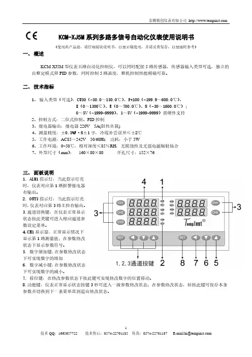
KCM-XJ5M系列多路多信号自动化仪表使用说明书(使用此产品前,请仔细阅读说明书,以便正确使用,并请妥善保存,以便随时参考)一、概述KCM-XJ5M型仪表五路自动化控制仪,可以同时配接5路传感器,传感器输入类型可选,独立的自整定模式和PID参数,同时控制5路温度,整机控制性能精确可靠。
二、技术指标1、输入类型(可选):CU50(-50.0~150.0℃)、Pt100(-199.9~600.0℃)、K(0~1300℃)、E(0~700.0℃)、S(-30~1600.0℃);0~5V(-1999-9999)、1~5V(-1999-9999)需硬件支持2、控制方式:二位式控制、PID控制3、继电器输出:继电器220V 5A(阻性负载)4、测量精度:±0.5%F·S±1字,冷端补尝误差≤±2℃5、工作电源:AC85~242V 50/60Hz 功耗:小于5W6、工作环境:0~50℃,相对湿度≤85%RH,无腐蚀性及无强电磁辐射场合7、外型尺寸(mm):160×80×80 开孔尺寸:152×76三、面板说明1. ALM1指示灯:当此指示灯亮时,仪表对应第1路报警继电器有输出。
2. OUT3指示灯:当此指示灯亮时,仪表对应第3路主控有输出。
3.通道切换键:在仪表正常显示状态按此类键可进入相应通道参数设定菜单。
4.CH1显示窗:正常显示情况下显示第1路测量值;在参数修改状态下显示参数符号。
5. 数字增加键:在参数修改状态下可实现数字的增加6. 数字减小键:在参数修改状态下可实现数字的减小。
7. 移位键:在修改参数状态下按此键可实现修改数字的位置移动。
8.功能键:仪表正常显示状态按键3秒可进入一级参数修改状态;在参数修改状态,轻按此键可保存本条参数并切换到下一条菜单直到退出修改状态。
四、仪表接线(以实物侧面接线图为准)五、基本设置及操作1、一级菜单设置按功能键(SET键)3秒,进入一级菜单,此时‘第1路显示窗’和‘第2路显示窗’分别显示参数符号和参数值,可分别按◄(移位键)、▲、▼三键来更改参数值,修改完成后按SET键保存进入下一个参数;同样方法修改其它参数。
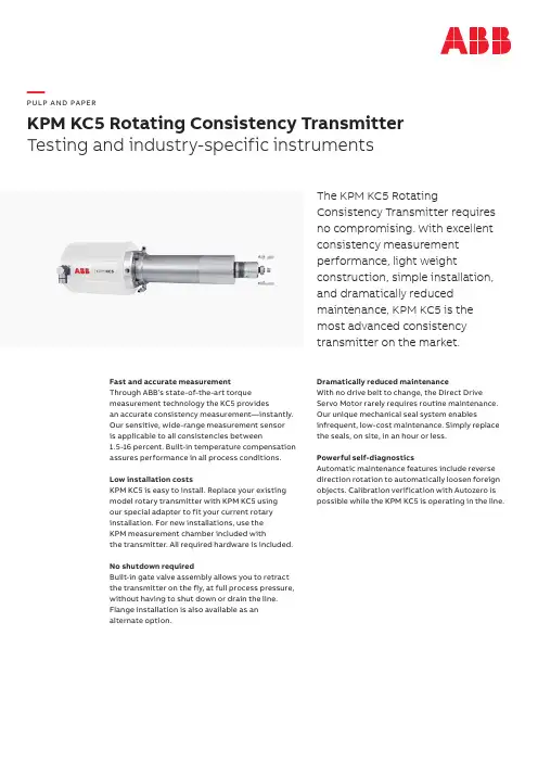
—PU LP A N D PA PERKPM KC5 Rotating Consistency TransmitterTesting and industry-specific instrumentsThe KPM KC5 RotatingConsistency Transmitter requiresno compromising. With excellentconsistency measurementperformance, light weightconstruction, simple installation,and dramatically reducedmaintenance, KPM KC5 is themost advanced consistencytransmitter on the market.Fast and accurate measurementThrough ABB’s state-of-the-art torque measurement technology the KC5 providesan accurate consistency measurement—instantly. Our sensitive, wide-range measurement sensor is applicable to all consistencies between1.5-16 percent. Built-in temperature compensation assures performance in all process conditions. Low installation costsKPM KC5 is easy to install. Replace your existing model rotary transmitter with KPM KC5 usingour special adapter to fit your current rotary installation. For new installations, use theKPM measurement chamber included withthe transmitter. All required hardware is included. No shutdown requiredBuilt-in gate valve assembly allows you to retract the transmitter on the fly, at full process pressure, without having to shut down or drain the line. Flange installation is also available as an alternate option. Dramatically reduced maintenanceWith no drive belt to change, the Direct Drive Servo Motor rarely requires routine maintenance. Our unique mechanical seal system enables infrequent, low-cost maintenance. Simply replace the seals, on site, in an hour or less.Powerful self-diagnosticsAutomatic maintenance features include reverse direction rotation to automatically loosen foreign objects. Calibration verification with Autozero ispossible while the KPM KC5 is operating in the line.3B L W K C 5i n t d e n 100SpecificationsSensor type Rotating consistency transmitterOutput signal Analog output 4–20 mA + HART®,Foundation Fieldbus and Profibus PA with optional converter Binary inputs 24 VDC (supplied from DCS), three for built-in calibration curves, one for process stop, one for sample buttonBinary output Alarm output; 24 VDC, 2A; opening or closing dry contact Power requirements 85–264 VAC, 47–63 Hz, 320W, single phase MotorIntegrated Direct Drive Servo Motor Measuring range KPM KC5-S: 2–16% consistency KPM KC5-100:1.5–5%Sensitivity Better than 0.003% CsPressure ratingSensor PN25Gate valve DN80 for KPM KC5-S: PN10, PN16 or PN25Gate valve DN125 for KPM KC5-100: PN16Process temperature 0–120° C (32–248° F)Ambient temperature Sensor 0–60° C (32–124° F), display unit 0–50° C (32–122° F) Flow velocity 0–5 m/s (0–15 f/s)Seal water Mill seal water, 6–8mm hose connection (¼”) Housing IP66 (better than Nema 4X) enclosureCabling 10 m (32 ft) interconnect cable from sensor to display unit; 20m (65 ft)and 30 m (98 ft) optionalGate valveDN80 (3”) AISI 316L standard, 254SMO and titanium available PN10, PN16 or PN25DN125 (5”) AISI 316L, PN16Process connectionMeasurement chamber fits pipe diameters of 150 mm (6”) and larger KPM KC5-100, 200mm or larger), AISI 316L standard, SAF2205, titanium. Adapter available for other manufacturer’s measuring vessels. All required installation hardware included in the delivery.Sensor material Wetted parts AISI 316L or titaniumDimensions (L × H × W) and weightsSensor: 520 × 140 × 180 mm (20.5 × 5.5 × 7.1”), 14,8 kg (33 lbs); KPM KC5-100, 19kg (42 lbs)Display unit: 200 × 300 × 150 mm (7.9 × 12 × 6”); 6 kg (13 lbs)Installation assembly: 430 × 560 × 200 mm (17 × 22 × 8”), 19 kg (42 lbs); KPM KC5-100, 28kg (62 lbs)/pulpandpaper—ABB OY, KPMKettukalliontie 9 E FIN-87100 Kajaani FINLANDTel: Tel: +358 10 22 11E-mail:*************.com—The information provided in this data sheet contains descriptions or characterizations of performance which may change as a result of further development of the products. Availability and technical specifications are subject to change without notice.Copyright© 2019 ABB. All rights reserved.。
前言非常感谢购买本公司生产的多功能过程校验仪。
本说明书解释了多功能过程校验仪的配置、操作方法和使用注意事项。
在使用多功能过程校验仪之前,请仔细阅读本说明书。
在充分理解的基础上,再对多功能过程校验仪进行操作。
●公司遵循持续发展的原则。
我们保留在预先不通知的情况下,对此说明书中描述的任何产品进行修改和改进的权利;保留在预先不通知的情况下,修订或废止本文档的权利。
对改进后的产品有相应的使用说明书或改进说明。
●本公司向最终用户保证,该仪表供货时的硬件、附件在材质和制造工艺上都不存在任何缺陷。
若在仪表到货之日起的1年质保期内收到用户有关这类缺陷的通知,本公司将对确实有缺陷的产品实行免费修理或更换。
本公司的所有产品均承诺终身维修。
2017年11月危险●严禁擅自拆卸、加工、改造或修理多功能过程校验仪,否则可能导致其动作异常,故障或报废。
由此造成的事故,本公司恕不负责。
●插孔之间的最高允许电压是30VDC,最大电流是25mA。
●当测试表笔的一端被插入电流插孔时,切勿将表笔另一端碰触电压源。
●切勿使用已损坏的多功能过程校验仪及其配件。
●请严格按照本说明书的各项说明进行操作,否则可能损坏多功能过程校验仪。
注意●首次使用多功能过程校验仪前,请确保电池电量充足。
●使用前务必保证多功能过程校验仪正常供电,并测量已知电压以确认多功能过程校验仪工作正常。
●使用多功能过程校验仪前应确定电池盖已关紧,在打开电池盖前请务必先把多功能过程校验仪的测试表笔拆下。
●根据使用要求选择正确的功能和量程档。
●使用测试探针时,手指应保持在探针的护指装置后,切勿触碰探针的金属触点。
●报废本产品时,按工业垃圾处理,避免污染环境。
目录1 概述.......................................................................................................... V II2 标准设备................................................................................................. V II3 初识多功能过程校验仪 (VIII)4 多功能过程校验仪概述 (IX)4.1插孔 .................................................................................................... I X 4.2多功能过程校验仪按键 (X)4.3显示屏幕 (XII)5 测量模式 (XIII)5.1测量电压、有源电流、欧姆和频率信号。
差压零位漂移对标准孔板流量计流量的影响摘要:天然气产销厂主要的计量方式采用的是变送器(流量管理器)配标准孔板的差压式流量计,该类型流量计的检定周期为一年,在一个检定周期内,仪表的差压零位会随着时间或温度而发生变化,这个微小的变化会对该类型流量计的流量计量产生何种程度的影响,是亟待研究的一项重要内容。
为此,通过在实验室内开展各项试验,对差压零位漂移进行数值模拟,找出差压零位漂移对不同气质,不同运行范围,特别是低限运行时的流量影响的规律,指导厂内各区站的日常检查。
并通过大量的试验及对试验数据的归类分析,找出了差压零位漂移对流量计量影响的规律。
关键词:差压零位漂移;标准孔板流量计;流量分析1现状调查1.1该类仪表的使用情况通过对全厂在用的流量计进行调查发现,我厂在用标准孔板流量计为170台,旋进旋涡流量计为61台,其它类型流量计,标准孔板流量计占到了全厂流量计总数的72.3%。
该类仪表的压力及差压变送器的精度均为0.2级。
1.2该类仪表的运行情况为了便于对该类型仪表的线性稳定性进行分析,我们选取了2台编号分别为T233648、T233651型号为2010TC的多变量变送器和2台编号分别为17961225、15841265型号为103的流量管理器近三年来的差压检定记录并对该表的线性度计算,整理汇总发现我厂在用的三合一变送器和流量管理器具有极佳的线性稳定性,所以得出结论:该类型仪表的差压零位发生漂移,将直接导致检定拟合曲线的整体漂移,也就是说,差压零位漂移量将直接导致各检定点的测量值发生与零位漂移量大小几近相同、方向也相同的变化量,从而对计量的数据产生影响。
2实验过程在该项目开展前,制定了详细的实验实施方案,并严格按照实施方案进行实施。
选取了一台编号为16970037型号为FB103的流量管理器来完成整个实验数据的采集工作,该表差压最大基本误差为0.03%,静压最大基本误差为0.02%,差压线性度为0.03%,静压线性度为0.02%,流量积算部分的最大基本误差为0.01%。
HART375手操器对罗斯蒙特3051系列变送器组态实训一、375手操器的使用按下图进行接线:1、变送器接线端子:左侧端子为24V电源正、中间端子为24V负(也称公共端)、右侧端子为检测电流信号端。
2、HART375手操器有两组插孔,一组为FF总线协议插孔另一端为HART协议插孔。
3、MCMC55 MC55是一台多功能校验仪,校验变送器时将变送器两个端子用导线连接到MC 上面标有2-W xmtr两个插孔上,按下MC5电源开关→D→D出现→设置窗口1和设置窗口2,窗口1一般设置为测量窗口、单位为mA,窗口2一般设置为压力窗口、单位可选择mpa、kpa、pa或其他压力单位。
选择完两个窗口后再按D键就可以校验变送器了。
4、在连接线路上串联一个250Ω的电阻为负载电阻,我们一般用电阻箱代替,把电阻箱旋钮拨到250Ω即可。
接完线检查无误,就可以通电对变送器进行组态和常规校验。
HART375手操器具体操作:1、打开电源开关等待375进入主菜单画面。
2、使用光标笔双击“HART应用栏”如果手操器与变送器通讯正常,则画面应转入在线状态。
此时双击“仪表设置”即可进入变送器的组态菜单仪表状态画面有五个选项:1双击“显示过程变量”后,你可以查看与变送器相关所有测量参数。
2进入诊断画面,你可以对也不进行各种校验及回路测试,另外变送器的各项报警也可以查看。
3进入“基本设置”你可以进行修改仪表位号;工程单位;变送器量程及阻尼时间。
因此,这是最常用的菜单,你可以双击5个选项的任何一个进入该菜单。
以下是菜单3:请注意:单击“左箭头”可以退回上一级菜单,单击“×”图标退回主HOME””退回到在线菜单(online,此菜菜单(此时可以关机),单击“HOME单为实时参数更新画面)。
3-1:修改单位:双击“单位“进入修改工程单位子菜单:ENTER””,这时候会告诉你使用光笔单击所选定的单位,然后单击“ENTER当前过程变量在该选定单位尚未发送至变送器之前仍然为原单位,提示你应在随菜单中进行发送(SEND),因此,见到提示后,即按OK则出现下随菜单:SEND””并在见到提示后,按OK,修改后的单位即下装到变送器中。
多功能校验仪校准TC及RTD通过优化环路校准测量系统,使其更好地支持温度检测元件的独有特征,能够大幅提高性能。
所有温度探头及其检测元件都是独一无二的,材料、结构、用途或者使用环境均各有不同。
这种独特性贯穿于传感器的整个使用寿命期间,表现形式为机械冲击和振动引起的漂移,或者暴露于被测材料时污染引起的漂移。
只有通过定期检定,才能适应这些差异和变化,提高总体测量性能。
在许多工业和商业过程中,温度的角色非常重要。
例如医药公司的灭菌、航空航天行业为确保最佳强度而进行的金属热处理、冷库中的温度检定,以及大气和海洋研究。
在所有温度测量应用中,传感器对结果的影响非常大;遗憾的是,在很多测量中,没有通过优化系统来获得温度传感器的最佳性能。
大多数过程温度测量是通过连接至变送器的检测元件实现的。
图1所示为常见配置的示意图。
在许多应用中,往往独立检定测量系统的检测元件,但这样往往忽略了将系统作为一个整体能够明显提高性能。
独立检定或校准检测元件的主要原因之一是这样做的效率更高。
利用电子热电偶(TC)或电阻温度检测器(RTD)模拟器,可简便、快捷地检定测量组件。
该方法不检定相关温度探头的性能,而是认为所有探头完全相同并严格遵守一定的标准。
在实际应用中,没有两个探头是完全相同的,它们全部会偏离理想标准,并且其特征随时间和使用发生变化。
Rosemount Inc.以表1为例,给出了关于644H型智能温度变送器可能实现的性能改善的信息。
为实现这一性能改善,为Rosemount 644H提供信息(Callendar Van Dusen方程系数),使其能够修正温度检测元件的独特性能,本例中为标准IEC751 Pt100传感器。
干井和微型恒温槽是检定温度探头及其他相关传感器的上佳选择,但是本身没有能力校准变送器的输出或读数装置,不能优化整个测量环路。
为了实现并保持上述的性能改善,需要一个热源,并结合能够校准变送器和读数装置的智能电子式过程校准器。
深圳市珈玛纳米电子有限公司NM5500多功能校准器使用说明书NM5500多功能校准器使用说明书深圳市珈玛纳米电子有限公司制造有限担保及责任范围深圳市珈玛纳米电子有限公司保证其每一个产品在正常使用及维护情形下,其用料和做工都是毫无瑕疵的。
保证期限是一年,并从产品寄运日起开始计算。
零件、产品修理及服务的保证期是90天。
本保证只提供给从深圳市珈玛纳米电子有限公司授权经销商处购买的原购买者或最终用户,且不包括保险丝、电池以及因误用、改变、疏忽、或非正常情况下的使用或搬运而损坏的产品。
深圳市珈玛纳米电子有限公司仅授权经销商将本保证提供给购买新的、未曾使用过的产品的最终用户。
经销商无权以深圳市珈玛纳米电子有限公司的名义来给予其它任何担保。
深圳市珈玛纳米电子有限公司的保证是有限的,在保用期间退回深圳市珈玛纳米电子有限公司的损坏产品,深圳市珈玛纳米电子有限公司有权决定采用退款、免费维修或把产品更换的方式处理。
欲取得保证服务,请与深圳市珈玛纳米电子有限公司服务中心联系,或把产品寄到深圳市珈玛纳米电子有限公司服务中心(请说明故障所在,预付邮资和保险费用)。
深圳市珈玛纳米电子有限公司不负责产品在运输上的损坏。
保用期修理以后,深圳市珈玛纳米电子有限公司会将产品寄回给购买者(预付运费)。
如深圳市珈玛纳米电子有限公司判断产品的故障是由于误用、改装、意外或非正常情况下的使用或搬运而造成,深圳市珈玛纳米电子有限公司会对维修费用作出估价,并取得购买者的同意以后才进行维修。
维修后,深圳市珈玛纳米电子有限公司会将把产品寄回给购买者(预付运费),同时向购买者征收维修和运输的费用。
本项保证是购买者唯一及专有的补偿,凡因违反保证或根据合同、侵权行为、信赖或其它任何原因而引起的特别、间接、附带或继起的损坏或损失(包括数据的损失),深圳市珈玛纳米电子有限公司一概不予负责。
操作安全性摘要警告高压端子上可能带有致命电压,请务必遵守所有安全注意事项!为防止触电危险,操作者不应与高压输出或高压检测接线柱以及连接到这些终端的电路产生带电接触。
MC5多功能校验仪
MC5多功能校验仪具有高度的测量精度和稳定性,能够提供可靠的数
据支持。
它采用先进的校准技术和自动补偿算法,能够实时校准和修正数据,确保测量结果的准确性。
同时,它还具有高速采样和数据传输功能,
可以实现实时监测和数据存储,方便后续的分析和处理。
MC5多功能校验仪具有友好的人机交互界面和丰富的操作功能,使用
起来非常方便和便捷。
它配备了大屏幕液晶显示器和触摸屏,可以直观显
示测量结果和参数设置。
并且,它支持多种通信接口,方便与其他设备和
系统进行连接和数据交换。
MC5多功能校验仪还具有强大的数据处理和分析功能,能够进行数据
趋势分析、统计分析和报表生成等。
它可以实时显示实测数据和标准值的
差异,并对数据进行可视化处理,帮助用户快速了解测量结果和系统运行
情况。
此外,它还支持数据导出和存储,方便用户进行后续的数据管理和
分析。
MC5多功能校验仪具有高度的安全性和可靠性,可在各种恶劣环境下
稳定工作。
它采用工业级的设计和材料,具有防尘、防水、耐高温等功能,能够适应各种复杂的工业现场环境。
同时,它还配备了安全保护装置和故
障自检功能,确保使用过程中的安全和可靠性。
综上所述,MC5多功能校验仪是一种功能全面、性能卓越的多功能测
量仪器,适用于各种工业现场的测量任务。
它不仅具有高精度、可靠性强
的特点,还具有丰富的操作功能和数据处理能力,帮助用户实现更加精确
和高效的参数测量和数据分析。