F1流量计算机操作手册
- 格式:doc
- 大小:1.81 MB
- 文档页数:11

OMNI流量计算机组态操作设置OMNI流量计算机操作方法一、OMNI基本操作1.1.键盘功能浏览面板上有34个键可用。
8个特殊的功能键和26个字母大写键A-Z,0-9和各种标点符号和数学符号。
位于右下部[Display/Enter]显示/回车键,值得特别关注。
此键用于执行一系列按键。
它不像个人电脑的回车键。
除了在一个领域里的输入值外,按键顺序的最大按键数是4,不包括[Display/Enter]显示/回车键。
每输入一个命令后按[Display/Enter]显示/回车键。
图1-1.计算机前面板键基本操作功能象在字母数字键上的‘Density’, ‘Mass’ and ‘Temp’密度、质量和温度键。
当按一定按键顺序按时,这些键单词代表的数据将被获得。
在许多情况下,对类似的按键计算机试图去识别一样的意思。
如:[Net] [1], [Meter] [1][Net] 和[Net] [Meter] [1] 都可以让运行#1号表的净体积值显示。
在大多数情况下,数据可以显示四行。
上下键可以帮助你滚动屏幕。
1.2. 操作模式1.2.1. 显示模式此模式下当前表的运行数据每200毫秒显示更新一次,此模式下数据不能被改变。
1.2.2. 键盘编程模式此模式下可以组态数据。
按[Prog] 键进入编程模式,Program LED指示灯变绿,当一个有效的密码被要求和输入后,此灯变红。
1.2.3. 诊断和校准模式按[Diag]键,[Alpha Shift]键,然后按[Prog]键,进入此模式。
此模式允许你检查和调整每一个输入和输出点的校准值。
DiagnosticLED 灯变绿,直到一个有效的密码被输入。
1.2.4. 现场输入模式当数据输入箭头是有效的,你就处于此模式。
当在编程或诊断模式时,用户输入了一个密码后。
1.3. 特殊的键1.3.1. Display/Enter(显示/回车)(Help)(帮助)键此键位于键盘的右下部。
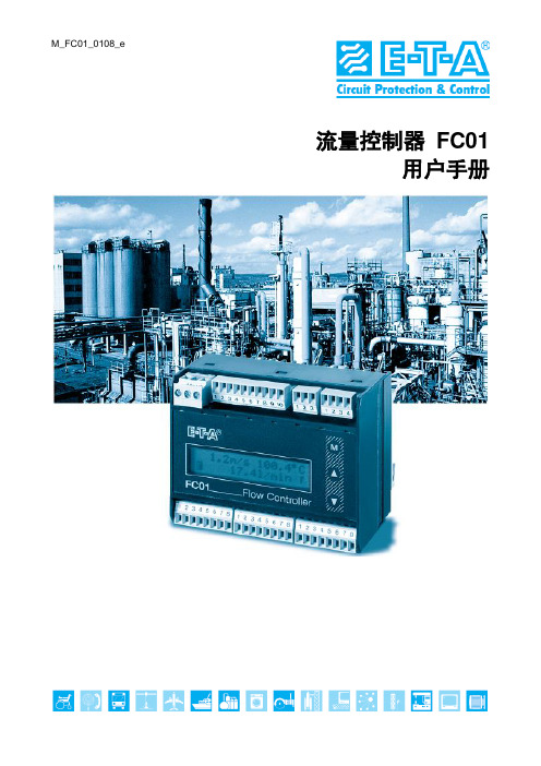
M_FC01_0108_e流量控制器FC01用户手册请认真遵守下列说明。
不遵守说明,或使用不当,可能对设备本身和安装设施造成严重损坏。
E-T-A 概不对客户或第三方承担责任,也不对由于未遵守这些说明造成安装不当或处理不当而引起的质保索赔或损坏负责。
该说明涵盖软件版本1.71。
设备安装、连接和调试只能由具备资格的专业人员进行!目录表1 描述 (1)1.1 测量程序 (2)1.1.1 量热测量程序 (2)1.1.2 机械程序 (3)1.2 系统描述 (4)1.2.1 用户界面 (5)2 安装 (7)2.1 量热监测探头的安装 (7)2.1.1 材料选择 (7)不锈钢1.4571 / AISI 316 Ti (7)镍基合金(哈式合金2.4610) (7)2.1.2 机械安装 (8)2.1.2.1 螺纹安装式监测探头CST-01 (8)2.1.2.2 监测探头CST-01 带可调浸入深度 (9)2.1.2.3 法兰安装式监测探头CSF-02 (10)2.1.2.4 卫生探头CSF-03(三夹钳式) (11)2.1.3 监测探头CST 安装说明 (12)2.1.3.1 液体介质 (12)2.1.3.2 气体 (13)2.1.3.3 密封 (14)2.1.4 监测探头CST 01 安装说明 (14)2.1.4.1 安装区和稳定区要点 (14)2.1.5 电气连接 (16)2.2 涡轮式传感器安装 (17)2.2.1 机械安装 (17)2.2.1.1 监测探头TST..AM1/WM1 (17)2.2.1.2 监测探头TST..HM2 (18)2.2.2 安装说明 (19)2.2.2.1 管道内安装 (19)2.2.3 电气连接 (20)2.3 电气控制单元FC01 的安装 (21)2.3.1 机械安装 (21)2.3.1.1 导轨安装式版本FC01-U1... .. (21)2.3.1.2 表面安装式版本FC01-FH-U1... .. (22)2.3.1.3 前面板安装式版本FC01-ST-U1... . (23)目录表I2.3.2 电气连接 (24)2.3.2.1 电路图FC01 24 V(继电器输出) (27)2.3.2.2 电路图FC01 24 V(晶体管输出) (28)2.3.2.3 电气连接–频率输出(版本FC01-U1T4) (29)3 操作系统 (31)键盘(M) 模式、(▲) 向上和(▼) 向下 (31)菜单翻页 (32)调出菜单选项 (32)输入数字 (32)转移输入 (32)删除数据 (32)4 操作和主菜单 (33)4.1 开关性能 (33)4.2 测量周期 (33)4.2.1 操作数据 (34)4.2.1.1 测量值 (34)4.2.1.1.1 量热监测探头CSx (35)4.2.1.1.2 涡轮式传感器TST (36)4.2.1.2 峰值(最小峰值/ 最大峰值) (37)4.2.1.3 上次误差 (37)4.2.1.4 主菜单 (38)5 配置 (39)5.1 监测探头选择 (39)5.2 监测探头数据 (40)5.3 介质选择 (40)5.4 限位开关组合 (41)5.5 流量单位 (41)5.6 介质温度单位 (42)5.7 显示器 (42)5.8 条形图 (43)5.9 管道直径 (44)5.10 频率输出 (44)5.11 模拟输出–流量 (45)5.12 模拟输出–介质温度 (45)5.13 退出配置菜单 (45)II 目录表5.14 配置菜单 (47)5.15 配置子菜单 (48)5.16 测量范围和菜单可及性 (51)6 参数选择 (52)6.1 测量时间 (52)6.2 限位开关1 开启/关闭值 (52)6.3 限位开关2 开启/关闭值 (53)6.4 定标因数 (54)6.5 退出参数选择菜单 (54)6.6 参数选择菜单 (55)7 误差 (56)7.1 测试和诊断 (56)7.1.1 优先组I (56)7.1.2 优先组II (56)7.1.3 优先组III (56)7.2 潜在误差 (57)8 技术数据 (59)8.1 环境条件 (59)8.2 电气特征 (59)8.2.1 电源供应 (59)8.2.1.1 直流供压 (59)8.2.1.2 交流供压 (60)8.3 模拟输出 (60)8.3.1 电压输出V1 - 5 V FS (61)8.3.2 电压输出V2 - 10 V FS (61)8.3.3 电流输出C1 - 20 mA FS (61)8.4 信号输出 (62)8.4.1 继电器输出R2 (DC 或AC) (62)8.4.2 晶体管输出(DC) (63)8.5 计量数据 (64)8.5.1 带量热监测探头的FC01 (64)8.5.2 用于FC01 / 选择器图表的量热监测探头 (65)8.5.3 带涡轮式传感器的FC01 (66)8.5.4 用于FC01 / 选择器图表的涡轮式传感器 (66)8.5.5 电气控制单元FC 01 (66)目录表III8.6 传感器接口 (67)8.6.1 量热监测探头接线端电气数据 (67)8.6.2 涡轮式传感器接线端电气数据 (68)9 附件 (68)索引附录1 操作和误差模式下数字及模拟输出的性能2 FC01 菜单结构(操作员对话框)IV 目录表1 描述流量控制器FC01 设计目的在于检测流量速度、流量体积以及介质温度,若使用了量热型监测探头(型号CSx)。
FIoBOSS S600流量计算机操作维护规程1 范围本标准给出了FloBoss S600流量计算机运行与维护的指南。
本标准适用于FloBoss S600流量计算机的运行与维护。
2 概述FloBoss S600接收流量计、天然气色谱仪和现场检测仪表的输入信号,进行计算、数据处理、批量下载数据和仪表校检;FloBossS600流量计算机配置带有浮点快速处理器的50MHzIntel 32-bit80486 DX2 CPU:FloBoss S600流量计算机相关技术参数见本标准的附录B。
3 FLoBoss S600操作3.1 前面板Front Panel3.1.1 前面板图示前面板的外观图见标准的附录A。
3.1.2功能键设置F Keys前面板键盘上部有四个黄色的功能键F1~F4,每个功能键可以设置成需要频繁浏览页面的快捷方式。
设置方法是:a) 直接进入到需要频繁显示的页面;b) 按“.”键:c)按一个功能键,示页面被赋值。
一旦一个功能键被赋值,则不能改变,但是可以重新对功能键赋值,以显示不同的页面。
3.1.3 方向和菜单键V ector and Menu Keys4个方向键位于“MENU”键的下面,用4个方向键可以浏览显示框、选择需要查看的参数或记录,或者进行数据修改。
在数据显示页,用“▲”或“▲”键分别查看前一页或后一页,当前显示页的页码数在页面底部的状态行指示。
在垂直移动查看其它显示行时,数据记录总是在那个行的第一个显示单元显示。
当输入或修改数据时,用“▲”键可作为删除/iE格键使用。
按“MENU”键将返回到上一级菜单。
如在数据显示页面,按“MENU”键将回到母菜单:按“MENU”键接着按“▲”键,不管当前处于哪级菜单,都将返回到主菜单。
3.1.4报警操作键A,arm Light and Keys在“F”键和“MENU”键之间是报警灯和“View”、“Accept”键。
在正常运行期间和无报警动作时,报警灯显示绿色:当有报警产生时,报警灯变为红色并闪烁,直到报警事件分别用“Accept”键和“View"键被确认和查看。
FI操作手册目录1.后台配置目标:检查货币代码2.后台配置目标:创建公司代码3.后台配置目标:创建公司4.后台配置目标:将公司代码分配给公司5.后台配置目标:创建会计科目表6.后台配置目标:定义科目组及输入控制7.后台配置目标:定义会计年度变式8.后台配置目标:创建信贷控制范围9.后台配置目标:维护公司代码的全局参数10.后台配置目标:定义字段状态变式11.后台配置目标:向字段状态变式分配公司代码12.后台配置目标:定义留存收益科目13.前台操作目标:新建一般资料负债科目14.前台操作目标:新建统驭科目—--—--应收/应付15.前台操作目标: 新建材料采购科目--—-GR/IR 16.前台操作目标:新建损益科目17.后台配置目标: 显示科目汇总清单18.后台配置目标: 复制凭证号范围到公司代码19.后台配置目标:定义记账期间变式20.后台配置目标:将记账期变式分配给公司代码21.前台操作目标:设置记账期间22.后台配置目标:为科目过账定义容差组23.前台操作目标:输入总账科目凭证24.前台操作目标: 显示总账科目余额25.后台配置目标: 维护自动税收过账26.后台配置目标:定义应收应付容差组27.后台配置目标:定义供应商账户组28.后台配置目标:定义供应商账户编号范围29.后台配置目标:分配供应商编号范围30.后台配置目标: 定义客户账户组31.后台配置目标: 定义客户账户编号范围32.后台配置目标:分配客户编号范围33.前台操作目标:新建订货方主数据34.前台操作目标:新建收货方主数据35.前台操作目标:新建供应商主数据36.前台操作目标: 输入客户发票37.前台操作目标:收到客户全部还款38.前台操作目标:显示应收账款余额39.前台操作目标: 显示客户余额40.前台操作目标:收到供应商发票41.前台操作目标:向供应商付款42.前台操作目标: 显示应付账款余额43.前台操作目标: 显示供应商余额44.前台操作目标:总账科目余额汇总表45.前台操作目标: 将收入成本科目设置为只能自动记账46.后台配置目标:定义资产负债和损益表结构47.前台操作目标: 运行资产负债表和损益表操作指南1 目标:检查货币代码后台配置路径:后台=>SAP用户化实施指南=〉一般设置=>货币=〉检查货币代码由于我们用到的人民币为RMB,但是系统默认的主要的人民币是CNY ,因此需要在此处将CNY对应的主要的勾去掉,在RMB对应的主要中打上勾。

M I C R O T H E R M O T E C H N O L O G I E S™MT Alliance – MT-Calc Quick Setup GuideDocument No. 72-MTA-1018-R0.2No part of this publication may be reproduced,stored in a retrieval system, or transmitted, in anyform or by any means, electronic, mechanical,photocopying, recording, or otherwise, withoutthe prior written permission of Micro ThermoTechnologies.© 1997-2015 by Micro Thermo Technologies.All rights reserved worldwide.Local Phone: (450) 668-3033 | Fax: (450)668-2695Toll Free Canada: 1-888-664-1406 | Toll Free USA: 1-888-920-6284/micro-thermoTable of Contents1Introduction (1)1.1Using this document (1)1.2Conventions used in this document (1)2Step by Step Procedure (2)2.1Installation and configuration of the Sensor Nodes (Univ Sen Node MT500) (2)2.2Installation of the MT EEPR Module in MT Alliance (4)2.3Adding the Plug-in (5)2.4Network Variable Connections (Bindings) (6)2.5Adding Custom Points to the Interface (7)2.6EEPR Configuration Using the Plug-In (8)3Typical EEPR Configuration (12)4Revision History (13)1Introduction1.1 Using this documentThis guide is intended for technicians installing MT-EEPR modules and sensor nodes. It is not a complete user guide, but rather a simple step-by-step summary of the basic instructions for the installation of an MT-EEPR module.A complete user guide and a user manual covering specifically the stand alone operation (using the board’s local interface) are available.1.2 Conventions used in this documentFor your convenience, several screen captures have been added to describe the procedures. Some images contain numbered balloons to help illustrate the procedure.Finally, bold text is used for emphasis or to highlight technical terms.1.3 The MT-CalcThe MT-Calc is a generic feature and we will use the MT-EEPR application as an example to explain it2Step by Step ProcedureIt is assumed that the Sensor Node button is dropped and the MT-EEPR module and the Sensor Node is powered and connected to the network.2.1 Installation and configuration of the Sensor Nodes (Univ Sen NodeMT-500 or MT-3208)It is necessary to configure the Sensor Nodes (Univ Sen Node MT500) before installing the MT-EEPR modules. These sensor nodes, as of version 4.1, support calculations on air temperatures that are used by the EEPR nodes and on defrost termination temperatures used by the Circuit nodes.The steps required to configure such a node are, typically:1-Install a Sensor Node, as usual.2-In the Sensor Node, go to the Calculation tab.A3-Click on the button (A). The following window opens:4-Configure the following points:A)Enter a description for the calculation block (Ex: Circuit using it)B)Select Temperature in the Physical Type drop-down list.C)Select the sensors that will be used in the calculations.D)Leave other default values as is.2.2 Installation of the MT-EEPR Module in MT Alliance1.In the Subsystems menu, select your subsystem or click the desired subsystembutton. In the Mode menu, select Configuration. When entering this mode, aComponents toolbox appears in the bottom right corner of the window. Itcontains all the items that can be dropped in the view.2.Select the view that you created at the previous step by clicking on the tabdisplaying its name.3.Drag and drop a Node icon from the toolbox to your process system view. Assoon as the icon is dropped, the Node Definition window opens. Select theitem representing the site installation in each drop-down list. Click the OKbutton to finish or Cancel to delete the node.*** To move an icon, select it and drag it with the left mouse button while holdingthe CTRL key.After the node is dropped, it must be configured and associated with the controller.The Installation steps (steps 4, 5 and 6 below) are deferred in the case of an off-lineconfiguration (the physical node being unavailable.)1.Click the node icon. The Custom Node Information dialog box opens.2.Select the Details tab.3.Type a unique name for the node in the Identification field and, optionally, inthe Notes field.4.Select the Commands/Status tab.5.In the Installation group, click the Install button.6.The Install a Custom Node dialog box opens and requests you to press theService button of the EEPR Node. For manual entry, please refer to the“Node Installation” manual. As soon as the node’s Service button is pressed,the software download begins. The plug-in loads the firmware into the node.Once the load is completed, the window buttons are activated.7.Click OK to close the window.8.Click YES to accept and save the changes.2.3 Adding the Plug-inAt this stage, the MT-EEPR controller contains the firmware, but the CPs (Configuration Properties) still have default values. The EEPR Plug-In is used to enter site specific information; it calculates the CPs and loads them into the node. It is used also to monitor the process.1.Drag and drop a Plug-in icon from the toolbox to the desired location on theview. Click on the plug-in icon to configure it.2.The Plug-In Information dialog box opens.3.Type the information as it is shown in the table below:Identification Type a unique and appropriate namePlug-InType MTScope NodeNode Name Use the name that you gave to the nodeManufacturer ID Micro Thermo Inc.Plug-in Name EEPRPlug-in Version 4.14.Click OK to save the settings and close the dialog box or click Cancel to undo thechanges.2.4 Network Variable Connections (Bindings)Network variables need to be bound to other nodes, for normal operation. Connections are shown in the table below.Please refer to the typical EEPR Configuration figure, on page 12, for a global configuration overview.~RackA.SGr1 nvoSP EEPRA1-5 nviSucGrXSP~RackA.SGr1 nvoSpStPt EEPRA1-5 nviSucGrXSPStPtnviAirTempX SNX nvoUnivCalc1X EEPRA1-5~RackA.CkC1 nvoCircStatusX EEPRA1-5 nviCircStatusXEEPRA1-5 nvoStatusX ~RackA.CkC1 nviEEPRStatusX1RTU1 nvoSpaceTemp EEPRA1-5nviSpaceTempnviSpaceRH RTU1 nvoRH EEPRA1-5N.B Create all connections for all MT-EEPR modules and create necessary circuit bindings for all variable indicated by X5.1 The binding of nvoSpaceTemp and nvoRH m ay be deferred until HVAC nodes become available to provide ambient temperature and relative humidity.2.5 Adding Custom Points to the InterfaceGiven the availability of data in the Plug-In’s Process page, it is suggested to drop only threecustom points for each circuit. They are described in the table below:Circuit 1EEPRA1-5 A1Setpoint Command Temperature nviAirTempStPt.Standby_coolTemp Measure Temperature nvoAirTemp.Standby_cool EEPRA1-5 A1EEPRA1-5 A1 % Open Measure Percent nvoY_Pos1Circuit 2Setpoint Command Temperature nviAirTempStPt.unoccupied_cool EEPRA1-5 A2Temp Measure Temperature nvoAirTemp.unoccupied_cool EEPRA1-5 A2EEPRA1-5 A2 % Open Measure Percent nvoY_Pos2Circuit 3Setpoint Command Temperature nviAirTempStPt.occupied_heat EEPRA1-5 A3Temp Measure Temperature nvoAirTemp.occupied_heat EEPRA1-5 A3EEPRA1-5 A3 % Open Measure Percent nvoY_Pos3Circuit 4Setpoint Command Temperature nviAirTempStPt.Standby_heat EEPRA1-5 A4Temp Measure Temperature nvoAirTemp.Standby_heat EEPRA1-5 A4EEPRA1-5 A4 % Open Measure Percent nvoY_Pos4Circuit 5Setpoint Command Temperature nviAirTempStPt.unoccupied_heat EEPRA1-5 A5EEPRA1-5 A5Temp Measure Temperature nvoAirTemp.unoccupied_heat EEPRA1-5 A5 % Open Measure Percent nvoY_Pos52.6 EEPR Configuration Using the Plug-InThe following represents the most specific aspects of setting up an EEPR module.1-Go to the System page and configure the following points:a)Select the valve series. (Sporlan, Alco 12 Volts or Alco 24 Volts)b)Enter the number of circuits on this module (1 to 5)c)Select the type of refrigerant (R22, R507 or R404A)d)Enter the value that you intend to use as a set point for the suction pressure (it willbe used by default)2-For each circuit, go in the Circuit page and configure the following points:a)Select the valve assigned to the circuit (Typically, valve 1 to circuit 1, valve 2 tocircuit 2, etc…)b)Enter the circuit’s nominal thermal load (as given by the manufacturer, usuallyspecified at 75°F and 55%RH ambient)c)Enter the intended air temperature set point (it will be used by default)d)Enter the nominal value of TD (TD being the temperature difference between thesensor and the saturated temperature of the evaporator (the nominal value is that specified by the case manufacturer, typically measured at 75 F ambient, 55% RH.) For refrigerated rooms, the TD as defined herein will be somewhat higher than that of the evaporator itself, because the sensor is usually installed in the return air flow.You may accept the suggested value if it is unknown.e)Click on Strategy Settings (see the “Settings” screen on the next page)f)Select the case’s type: Doors, Open or Coffing)OR select the refrigerated room type: With Doors or Open Areah)Select the product type of circuit in the drop-down listi)If the circuit is equipped with high performance evaporators, clicking on the relevantcheck box will change the suggested TD, provided it has never been edited.j)If you specify the type of merchandise, the default values of the relevant parameters will be adjusted automatically, provided they have never been edited.3-Go to the Valve page and configure the following points for each valve:a)Select the valve model in the drop-down listb)Select the control type in the drop-down list (Circuit in this case)c)Leave the default value (SG-1) for the Suction Group4-Apply changes by clicking on the Apply button in the bottom of the plug-in window:The process can now be monitored via the Process page.3Typical EEPR ConfigurationThe figure below shows the bindings between an EEPR node and the other nodes (SPC, Sensor, Circuit, HVAC) in a typical application.0A-10A-20A-3S1S2S3S4S5S6S7S8Circuit 4 : standby_heatCircuit 5 : unoccupied_heatEEPR2_Bindings_Spec62.vsdLast edit : Fri, Jan 30, 20044Revision History0.1 Creation of the document, modeled from 71-GEN-0093RL 18-feb-04 (PDF intérimaire)0.2 Cover page and formatting ER 30-Mar-2015。
From The FIA Formula One Race Director ToAll Teams, All OfficialsDocument 29Date 11 October 2020Time12:422020 E IFEL G RAND P RIX8 - 11 October 2020The FIA Formula One Race DirectorTitle Race Directors' Event Notes Version 4Description Event Notes Version 4Enclosed2020 Eifel F1 Grand Prix Event Notes V4 Doc 29 111020.pdfMichael Masi2020E IFEL G RAND P RIX8 - 11 October 2020From The FIA Formula One Race Director Document29To All Teams, All Officials Date10 October 2020Time 12:45EVENT NOTES VERSION 4General Instructions1) Pit lane map1.1 Safety Car lines.1.2 The location of the pit entry and the pit exit.1.3 Designated garage areas.1.4 Safety Car position for first lap and rest of race.1.5 Blue flag marshal at the pit exit.1.6 Track light panels displaying pit entry status.2) Pirelli Event Preview2.1 With reference to Article 24.4(a) of the Sporting Regulations see the attached document provided bythe official tyre supplier.3) Red zones for photographers in the pit lane during practice sessions3.1 See the attached drawing.4) Track light panels4.1 The FIA track light panels have been installed in the positions shown on the circuit map. Inaccordance with Appendix H to the ISC the light signals have the same meaning as flag signals.5) Track light panel displaying pit entry status5.1 The light panel indicated on the pit lane map will display a flashing yellow arrow if cars are requiredto use the pit lane once the Safety Car has been deployed during the race.5.2 The light panel indicated on the pit lane map will display a flashing red cross if the pit lane is closedat any point during the race.6) Drivers leaving their pit stop position in the pit lane6.1 For safety reasons, no car should be driven from its pit stop position at any time unless:a) It has first been driven into the pit stop position having just entered the pit lane from the track,and;7) Observing yellow flags during free practice and qualifying7.1 Double waved: Any driver passing through a double waved yellow marshalling sector must reducespeed significantly and be prepared to change direction or stop. In order for the stewards to be satisfied that any such driver has complied with these requirements it must be clear that he has not attempted to set a meaningful lap time, for practical purposes this means the driver should abandon the lap (this does not necessarily mean he has to pit as the track could well be clear the following lap).7.2 Single waved: Drivers should reduce their speed and be prepared to change direction. It must beclear that a driver has reduced speed and, in order for this to be clear, a driver would be expected to have braked earlier and/or discernibly reduced speed in the relevant marshalling sector.Drivers should not overtake any car in a single waved yellow marshalling sector unless it is clear thata car is slowing with a completely obvious problem, e.g. obvious accident damage or a deflated tyre.8) In laps during qualifying and reconnaissance laps8.1 In order to ensure that cars are not driven unnecessarily slowly on in laps during and after the endof qualifying or during reconnaissance laps when the pit exit is opened for the race, drivers must stay below the maximum time set by the FIA between the Safety Car lines shown on the pit lane map.You will be informed of the maximum time after free practice 3.9) Parc Fermé Cameras9.1 To assist with the revised FIA Event procedures, the Parc Fermé cameras must be uncovered andoperational at all times during the Event.10) Operational personnel curfew10.1 Boards warning anyone attempting to enter the paddock that the curfew is in operation will be placedimmediately before the turnstiles at the appropriate times.10.2 At this Event, Personnel will be permitted to enter the Paddock 30 minutes prior to the curfew toassist social distancing. No work is permitted to be undertaken until the curfew has ended.11) Tyre Blanket Usage during Pit Stops in the Race11.1 For reasons of safety, tyre blankets are not permitted in the Pit Lane at any time during the race.12) Lapping during the race12.1 The ISC requires drivers who are caught by another car about to lap him to allow the faster driverpast at the first available opportunity. The F1 Marshalling System has been developed in order to ensure that the point at which a driver is shown blue flags is consistent, rather than trusting the ability of marshals to identify situations that require blue flags.As it was at the end of last season the system will be set to give a pre-warning when the faster car is within 3.0s of the car about to be lapped, this should be used by the team of the slower car to warn their driver he is soon going to be lapped and that allowing the faster car through should be considered a priority. When the faster car is within 1.2s of the car about to be lapped blue flags will be shown to the slower car (in addition to blue light panels, blue cockpit lights and a message on the timing monitors) and the driver must allow the following driver to overtake at the first available opportunity.It should be noted that the aim of using F1MS is ensure consistent application of the rules, additional instructions may also be given by race control when necessary.Event Specific Instructions13) Formula 1 Sporting Regulations Article 21.613.1 In accordance with the provisions of Article 21.6a) i), this Event is a Closed Event.14) Changes to the circuit14.1 This is a new event.15) Specific Technical Procedures for Closed Events15.1 The provisions of Technical Directive Ref: TD/039-20 C and the “Pirelli HSE procedures” must becomplied with at all times during the Event.15.2 Any tyres that are removed from a car and could be re-used during a session should be presentedfor scanning before being rewrapped and reheated. If time constraints do not permit this then all tyres used during a session must be presented to the tyre checker at the front of the garage the end of any session. This applies to dry, wet and intermediate tyres.15.3 Both TD/039-20 C and the “Pirelli HSE procedures” will be amended after the Event to reflect anyadditional operational requirements as required.16) Weighing and weighing platform16.1 The FIA weighing platform will be available for teams to use at the following times, however, no morethan 8 team personnel may be present during any visit. Each visit should last no more than 10 minutes unless no other team is waiting in the pit lane:a) From 11:00 on Thursday until 10:00 on Friday.b) From 12:30 on Friday until 14:30 on Saturday (between 13:00 and 14:30 each visit will berestricted to five minutes).c) From when the cars are returned to the teams after qualifying until 19:30 on Saturday.d) From 09:00 until 10:00 and 12:00 until 13:30 on Sunday.Any team found to be abusing the time limits set out above, which we will be enforced by FIA security personnel and our own CCTV, will not be permitted to use the weighbridge again during the Event.16.2 When queuing for the weighing platform, tyre blankets, which use resistive heating elements, maybe used at ambient temperatures below 15 °C. The reference for this is the temperature published on Page 3 of the Official Messaging System. The blankets must be properly fastened around the tyre and done up tightly and may not cover any car components other than the wheel.17) Support Races17.1 Team Barrier placementa) Team barrier placement prior to and during all support category practice sessions and races:No more than three metres from the garages.b) It is not permitted to push cars to the weighing area at any time a support category is in pitlane.17.2 Support Category Movementsa) Support Crews and Trolleys will be released into Pit Lane no earlier than 20 minutes prior tothe opening of Pit Exit for their respective sessions.b) Support Category competition vehicles will be release from the marshalling area no earlierthan 15 minutes prior to the opening of Pit Exit for their respective sessions.18) Practice starts18.1 During each practice session, practice starts may only be carried out on the right-hand side prior tothe derestriction line indicated by the white grid marking. Drivers wishing to carry out a practice start should stop on the right in order to allow other cars to pass on their left. See attached image 1. 18.2 During the time the pit exit is open for the race, practice starts may be carried out after the end ofthe pit wall and adjacent to the orange band on the right-hand side barrier. Drivers wishing to carry out a practice start should stop on the right in order to allow other cars to pass on their left. See attached image 2.During this time any driver passing a car which has stopped to carry out a practice start may cross the white line that is referred to in 19.1 below. Any driver crossing this line must move back to the right of it as quickly as possible.18.3 For reasons of safety and sporting equity, cars may not stop in the fast lane at any time the pit exitis open without a justifiable reason (a practice start is not considered a justifiable reason).19) Lines or bollards at the Pit Entry and Pit Exit19.1 In accordance with Chapter 4 (Section 5) of Appendix L to the ISC drivers must keep to the right ofthe solid white line at the pit exit when leaving the pits. No part of any car leaving the pits may cross this line.19.2 For safety reasons drivers must keep to the right of the first bollard at the pit entry when they areentering the pits.19.3 Except in the cases of force majeure (accepted as such by the Stewards), the crossing by any partof the car, in any direction, of the white line and/or the red and white painted area, between the pit entry and the track, by a driver who, in the opinion of the Stewards, had committed to entering the pit lane is prohibited.19.4 The dotted white line across the pit entry and across the pit exit are the track edge line.20) DRS20.1 DRS Detection will be automatically disabled in each individual zone if any of the light panels in thatparticular zone are displaying yellow. The zone and corresponding light panels are as follows:a) Zone 1: Panels 14, 15, 16b) Zone 2: Panels 1, 2, 1821) Track Limits21.1 Turn 4 - Exita) A lap time achieved during any practice session or the race by leaving the track (all four wheelsover the white track edge line) on the exit of Turn 4, will result in that lap time being invalidatedby the stewards. See new attached image 3 displaying the track edge line.21.2 General - Turn 4 Exita) Each time any car fails to negotiate Turn 4 Exit by using the track, teams will be informed viathe official messaging system.b) On the third occasion of a driver failing to negotiate Turn 4 Exit by using the track during therace, he will be shown a black and white flag, any further cutting will then be reported to thestewards.c) In all cases detailed above, the driver must only re-join the track when it is safe to do so andwithout gaining a lasting advantage.21.3 Turns 13-14a) Drivers are reminded of the provisions of Article 27 of the Sporting Regulations and in particularArticles 27.2 and 27.3.b) A lap time achieved during any practice session or the race by leaving the track and failing tonegotiate Turn 13 -14, will result in that lap time being invalidated by the stewards.c) Each time any car fails to negotiate Turns 13-14 by using the track, teams will be informed viathe official messaging system.d) As a guide and as discussed at the Drivers Meeting, a lasting advantage will be monitored untilthe exit of Turn 1.22) Fire extinguishers around the circuit22.1 Indicated by small fluorescent orange boards behind the barriers.23) Places to remove cars from the track23.1 Indicated by fluorescent orange panels on the barriers.23.2 Should a car stop on the track during a session, the driver must keep all of their protective clothing(Helmet, Gloves, etc) on until they have returned to their garage.23.3 If a driver has a choice where to stop during a session, it is recommended they do so on the right-hand side of the track as cars may then be recovered more easily and brought back to the pits.24) Sporting Regulations Article 36.424.1 In addition to the provisions of Article 36.4, and for reasons of safety, tyre blankets must bedisconnected from any power supply at the five-minute signal and must not be reconnected during the start procedure, unless the delayed start signal is shown.25) Access to the grid prior to the Start Procedure25.1 To assist social distancing in accessing the grid prior to the commencement of the start procedure,Team personnel and equipment will be granted access to the grid from 1310hrs on Sunday 11th October.26) Removing cars from the grid26.1 Either through the pit exit or the gate in the pit wall located adjacent to grid position 14.27) Car number light panels for the start27.1 On the right-hand side of the grid.28) Sporting Regulation Article 42.328.1 For reasons of safety, Article 42.3 is amended as follows with the additions displayed with doubleunderline:42.3 When the five minute signal is shown all cars must have their wheels fitted, after this signalwheels may only be removed if the car has been moved out of the fast lane or during a furtherrace suspension.A penalty under Article 38.3(d) will be imposed on any driver whose car did not have all itswheels fully fitted at the five minute signal or has any of its wheels changed before it leavesthe pit lane after the race has been resumed.At the two minute point any cars between the safety car and the leader, in addition to any cars29) Post-race parc fermé29.1 All cars must enter the pit lane and, with the exception of the first three, should be driven directly tothe weighing area at the pit entry. The first three must follow the post-race procedure which will be distributed prior to the start of the race.30) Any other businessMichael MasiFIA Formula One Race DirectorIMAGE 1 – PRACTICE START LOCATION - PRACTICE SESSIONSPRACTICE START LOCATIONDURING EACH PRACTICESESSIONIMAGE 2 – PRACTICE START LOCATION – PRIOR TO THE RACE PRACTICE START LOCATIONPRIOR TO THE START OF THERACE INDICATED WITH THE REDARROW ABOVEIMAGE 3 – TRACK EDGE LINE TURN 4 EXITWHITE TRACK EDGELINE INDICATED WITHTHE RED ARROW BELOWS1S2T131234567891011121415M 43M 45M 44M 47M 46M 49M 48M 50M 42M 1M 2M 41M 6M 3M 4M 5M 10M 11M 12M 33M 9M 34M 13M 31M 30M 14M 15M 29M 28M 18M 16M 17M 19M 20M 27M 21M 22M 26M 25M 23M 24M 7M 8M 37M 36M 35M 38M 39M 40M 40aM 32DRS DETECTION 1DRS ACTIVATION 1DRS ACTIVATION 2DRS DETECT 2123746138910111214151718516Circuit Centreline Length = 5.148 kmCircuit MapVERSION 3 - ISSUED 07.10.20© 2020 Formula One World Championship LimitedThe F1 FORMULA 1 logo, F1 logo, FORMULA 1, FORMULA ONE, F1, FIA FORMULA ONE WORLD CHAMPIONSHIP, GRAND PRIX and related marks are trade marks of Formula One Licensing BV, aFORMULA 1 ARAMCO GROSSER PREIS DER EIFEL 2020 - Nürburgring15S2S1T Corner Numbers Speed Trap Sector 2Sector 1Control Line Start LineMarshal Post M22FIA Marshal Light Number & Location18DRS Detection 1DRS Detection 2DRS Activation 2DRS Activation 1 [55m after Turn 11] [115m before Turn 15] [90m before Turn 5] [85m after Turn 11] [165m before Turn 13] [45m before Turn 10] [73m after Turn 15]GENERAL NOTESV e r s i o n 1 –7 O c t o b e r 2020P i t L a n e2020 E i f e l G r a n d P r i x© 2020 F o r m u l a O n e W o r l d C h a m p i o n s h i p L i m i t e dT h e F 1 F O R M U L A 1 l o g o , F 1 l o g o , F O R M U L A 1, F O R M U L A O N E , F 1, F I A F O R M U L A O N E W O R L D C H A M P I O N S H I P , G R A N D P R I X a n d r e l a t e d m a r k s a r e t r a d e m a r k s o f F o r m u l a O n e L i c e n s i n g B V , a F o r m u l a 1 c o m p a n y . T h e F I A l o g o i s a t r a d e m a r k o f t h e F éd ér a t i o n I n t e r n a t i o n a l e d e l 'A u t o m o b i l e . A l l r i g h t s r e s e r v e d .F O R M U L A 1 A R A M C OG R O S S E R P R E I S D E R E I F E L 2020G A R A G E S456789101112131415161718192021222324252627282930313233123W a l k w a yR E D Z O N E R E D Z O N E R E D Z O N E R E D Z O N ER E D Z O N E。
流量计说明书流量计说明书篇一:流量计使用方法及问题解析流量计外观及使用方法如下所示:接线时1,2,3是电源端使用的是24V供电4是数字量输出,也就是说该引脚输出一定频率的信号,信号的频率与流量相关。
频率关系为1HZ的频率对应一单位NV的的流量(该单位不是清楚是什么)5是模拟量输出,输出的是4-20mA的电流信号,电流大小与流量线性相关。
6、7是RS232串口输出,RXD接收端,TXD发送端。
该端口可以提供与PC的通信功能,也就对应需购买的软件。
连接方式为RX对应9针串口(电脑端口)的2,TX对应9针串口的3,GND 对应9针串口的5。
问题分析及解决方法1、流量计自带LCD屏显示功能,如果不能正常显示说明,电源未正确连接,检查123接线是否正确。
2、如未配液晶屏,需购买。
或通过3条中模拟量或数字量的自制显示单元实现(成本不会很高)3、如果正常显示,流量数显示不正确,说明参数未配置正确 1是输出流量没规律,说明流量计是坏的,需更换2输出线性相关只是大小不正确可通过以下方式解决1)通过串口发送命令对传感器重新标定或设定,但是通信协议需厂家提供。
厂家提供的软件不一定有该功能。
2)通过模拟量输出口,测量输出电流,然后将电流与流量相对应,对应关系可自己设定。
自己做一个小控制器通过这个关系将流量重新显示。
3)通过数字量口,测量频率信号,然后对应流量信号,也需要自己做控制器显示。
4、另一种可能是测量程不匹配,可参照下表确认,内径与最大最小流量的关系流量计说明书篇二:超声波流量计说明书SCT超声波流量计说明书(固定式、便携式通用)MKflo-2000F系列中文版超声波流量计说明书目录一概述 (4)1.1 引言 (4)1.2 SCT的特点 (4)1.3 工作原理 (4)1.6 可选备件 (5)1.7产品型号编码规则 (5)1.8接线图 (6)1.9 性能指标 (6)二开始安装测量 (8)2.1 开箱检查 (8)2.2 供电电源 (8)2.2.1 便携式 (8)2.2.2 固定式 (8)2.2.3 接线 (8)2.3 通电 (8)2.4 键盘 (8)2.5 怎样操作 (9)2.6 窗口简介 (10)2.7 快速输入管道参数和步骤 (10)2.8选择测量点 (11)2.9 探头接线 (11)2.10 安装探头 (12)2.10.1 探头安装距离 (12)2.10.2 探头安装方式 (12)2.10.3 V法 (12)2.10.4 Z法 (12)2.10.5 N法(不常用的方法) (13)2.10.6 W法(极不常用的方法) (13)2.10.7 插入式传感器的安装 (13)2.11 检查安装 (17)2.11.1 信号强度 (17)2.11.2数据数量 (18)2.11.3 总传输时间、时差 (18)2.11.4 传输时间比 (18)2.11.4 安装时注意的问题 (18)三怎样使用 (19)3.1 怎样判断流量计是否工作正常 (19)3.2 怎样选择流量单位制 (19)3.3 怎样选择瞬时流量单位 (19)3.4 怎样选择累积流量单位 (19)3.5 怎样选择累积器倍乘因子 (19)3.6 怎样打开或关闭流量累积器 (19)2MKflo-2000F系列中文版超声波流量计说明书3.7 怎样实现流量累积器清零 (19)3.8 怎样恢复出厂设置 (19)3.9 怎样使用阻尼器稳定流量显示 (20)3.10 怎样使用零点切除避免无效累积 (20)3.11 设置零点提高测量精度 (20)3.12 修改仪表系数(标尺因子)进行标定校正 (20)3.13 密码保护(加锁与开锁) (20)3.14 怎样使用打印机 (21)3.15 怎样使用4~20mA电流环输出 (21)3.16 怎样输出模拟电压信号 (21)3.17怎样输出累积脉冲 (21)3.18 怎样使用OCT输出 (21)3.19 怎样修改日期时间 (21)3.20 怎样调整LCD显示器 (22)3.21 怎样使用RS232串行口 (22)3.22怎样查看每日、每月、每年流量 (22)3.23 怎样对模拟输出进行校准 (22)3.24 查看电子序列号和其他细节 (22)四命令/显示窗口详解 (23)4.1 显示窗口一览表 (23)4.2 显示窗口顺序介绍 (24)五问题处理 (41)表1. 硬件上电自检信息及原因对策 (41)表2. 工作时错误代码原因及对策 (42)其他常见问题问答 (43)六热量和其他物理量测量 (44)6.1 功能介绍 (44)6.2热量测量硬件接线 (44)6.3怎样进行热量测量 (44)6.4温度、压力等信号的量程范围设置 (44)6.5联网时模拟输入量的读取 (44)七质量保证及服务维修支持 (45)7.1 质量保证 (45)7.2 公司服务 (45)7.3 产品升级 (45)7.4 技术咨询 (45)八附录 (46)8.1常用液体声速和粘度 (46)8.2 常用材料声速 (46)8.3水中声速表(1标准大气压下) (47)3MKflo-2000F系列中文版超声波流量计说明书一概述1.1 引言欢迎您选择使用性能更优异、功能更多、采用专利技术制造的MKFLO-2000F系列中文版超声波流量计。
s600流量计算机操作规程FloBoss S600 流量计算机操作维护手册1. 面板操作1.1 功能键设置 F Keys前面板键盘上部有四个黄色的功能键 F1,F4~每个功能键可以设置成需要频繁浏览页面的快捷方式。
设置方法如下:1.1.1 直接进入到需要频繁显示的页面,1.1.2 按“.”键,1.1.3 按一个功能键~显示页面被赋值。
一旦一个功能键被赋值~则不能改变~但是可以重新对功能键赋值~以显示不同的页面。
1.2 方向和菜单键Vector and Menu Keys4个方向键位于“MENU”键的下面~用4个方向键可以浏览显示框、选择需要查看的参数或记录~或者进行数据修改。
在数据显示页~用或键分别查看前一页或后一页~当前显示页的页码数在页面底部的状态行指示。
在垂直移动查看其它显示行时~数据记录总是在那个行的第一个显示单元显示。
当输入或修改数据时~用键可作为删除/退格键使用。
按“MENU”键将返回到上一级菜单。
如在数据显示页面~按“MENU”键将回到母菜单,按“MENU”键接着按键~不管当前处于哪级菜单~都将返回到主菜单。
1.3 报警操作键Alarm Light and Keys在“F”键和“MENU”键之间是报警灯和“View”、“Accept”键。
在正常运行期间和无报警动作时~报警灯显示绿色,当有报警产生时~报警灯变为红色并闪烁~直到报警事件分别用“Accept”键和“View”键被确认和查看。
在报警未确认之前~报警数据和时间交替显示。
若有多个报警事件时~以事件时间顺序显示。
除非报警故障被排除~否则报警灯一直呈红色。
如果报警灯显示黄色~说明显示屏、键盘故障~或者是前面板与CPU模块之间通讯失败。
1.4 数字键Numeric Keys键盘下部分数字“0,,”、小数点“.”和减号“-”键组成~其功能是:——数字0,,用来输入和修改数据~引导显示矩阵。
——负号“-”用来定义FloBoss S600的默认显示页的快捷方式。
江苏省天然气有限公司安全生产部文件F1流量计算机使用说明和维护指南一. 目的为确保天然气管道流量设备的安全运行,制定本作业指导书。
二. 使用范围本作业指导书适用于锡沙线各天然气输气场站流量计算机三.流量计算机技术指标F1流量计算机技术指标:1.输入:每个通道有两个脉冲输入适合低频和高频脉冲发生器输入输入最高频率为10kHZ,每个通道的输入频率可自动调整每个通道还可以作为编码计数器输入,用于原始仪表读数的数字传输.每个通道可以连接一个四线制的温度传感器PT100,其测量误差在测量范围是-10~60℃,环境温度为0~40℃时是+0.05%,每个通道可以连接一个测量范围为4~20mA 的压力传感器其测量误差在测量范围是4~20mA,环境温度为为0~40℃时是测量值的+0.05%,该输入最多可选接四个带有HART 接口的压力和温度传感器2.输出:输出板带有一个继电输出最大28.8V 120mA 该输出可用于消息输出三个晶体管,输出最大28.8VDC 90mA 可以用于消息输出或体积脉冲输出最大25Hz 两路模拟量,输出用于测量值输出输出电流范围为0 到20mA 最大负载阻抗为300 欧姆测量误差,在测量范围是4~20mA 环境温度是0~40 时是输出值的+0.1%3.电源:24VDC +/- 20%,带有3块处理板时的输入功率大约为6W,可选230VAC 外部电源供电.4.接口:符合DVGW Worksheet G485 和 DSfG 实现的技术规范的DSfG 接口,通过DSfG 可以查询校正和数据记录文档,DDS数据接口可以用于连接计算机或笔记本电脑的COM 接口从而可以在调试和文档查询时进行参数设置,HSBus﹝高速总线﹞可以用于连接几个gas-net 模块以实现快速处理应用,COM2接口﹝符合RS232C标准﹞用于连接MODEM,根据V.34bis,其最大传输速率可达,33600bps数据压缩格式为V.42 或NMP5,DCF77接口用于无线时钟接收器的连接. 四.流量计算机技术指标1.前面板视图2.下面的接口处于设备背板上的其它接口之中一个多功能输入板EXMFE4,该输入板不仅可以用于连接压力和温度传感器还可以用于连接天然气表对于双通道运行的情况将会提供第二块EXMFE4,以用于第二通道的处理连接一个或两个多功能输出板 MFA6 该输出板可以用于体积脉冲消息和测量数据的输出 DSfG 总线连接HSB 总线连接以备将来使用24V DC 电源连接3.键盘:gas-net设备的键盘由一个用于数字输入的数字键盘负号键小数点键以及四个导航键组成,通过这些导航键操作员可以在菜单中进行移动从而调用相应的菜单,并进行显示在某些情况下通过导航键可以触发某些动作或改变某些参数值,下图显示了键盘上每个键的含义:4. 显示器显示器是一个8 行每行32 个字符的发光LCD 如果30 分钟内没有按键显示器的背灯将自动关闭.5.状态显示LED 和标定开关:LED 的状态含义红色闪烁正在发生一个警告即发生一个影响体积修正的错误黄色闪烁正在发生一个警报即发生了一个事件但该事件不影响体积修正绿色闪烁在电源供电失败后的启动阶段出现一个绿色闪烁的灯红色不闪烁发生了一个警告但该警告已经不存在接受该警告可以从错误生或是否已经发生了错误下表解释了各个颜色的具体含义6.设备面板五.流量计算机gas-net F1 设备的操作1.例子体积修正仪Z0和Z1的基本显示器,就是校正模块的主显示器流量计算机F1可以进行双通道操作在这种情况下,每个通道都有一个校正模块在这种情况下,该设备的基本显示器就是第一通道校正模块的主显示器,显示器是用来显示参数值的,如果要显示的内容多于显示器所能显示的个数那么在显示器的右边就会出现向上和向下的方向键指示您可以向上或向下进行滚动显示。
在能够导航菜单之前必须先按一下菜单键,这样在显示器的右边将会出现一个,包含当前菜单所有子菜单的列表,通过箭头键您可以在被调用菜单中上下移动,从而选择相应的菜单项,这些菜单项要么指向其它模块的主显示器,要么指向附属显示器或者对话框,某些情况下,也可以用来释放某个特定的动作,比如将计数器的指示器改为显示小数点后面部分,作为一个典型的例子下图显示了Z0 或Z1 校正模块的菜单。
被选中的菜单项是被反向显示的即黑色背景绿色文本按下回车键可以激活被选入口的菜单项例子假定希望从Z0 或Z1 的基本显示器切换到监测模块的主显示器首先按下菜单键打开菜单窗口在所显示的列表中第一个入口被默认选中即第一个入口是黑色背光显示,然后不断地按向右箭头键直到监测菜单项被选中,此时按回车键将会显示监测模块的主显示器。
例子打开体积修正仪Z0 或Z1 的修正开关提示只有在锁打开的情况下才可以这样做在相关的菜单项被调用后将会出现如下的显示框。
上图中修正开关显示是关闭的假定想要打开这个开关按回车键进入编辑模式将会打开一个包含可用值的选择列表在本例中只有打开和关闭这两个可选值通过,箭头键选择想要设定的值在本例中选择打开相应的显示窗口如下:按回车键退出编辑模式显示菜单。
选择确定来确认新的设定值或选择取消来放弃新的设定值。
一次同时改变几个参数值,绝大多数对话框不单独提供所要修改的参数而是作为一个集合提供所有要修改的参数,在这种情况下必须先编辑首先选中的参数值,按回车键可以切换到编辑模式按回车键可以移动到下一个参数值。
例子假定想要修改体积修正仪Z0 或Z1 中的天然气品质参数表该表有相应的用户连锁保护因此我们假定该锁是打开的从校正模块的主显示器中激活天然气品质菜单选项将出现如下的显示窗口。
当前所显示的指示值是有效的缺省情况下第一个输入口已经被选中按回车键可以修改第一个参数的值参数值后面闪烁的插入符_ 表明现在已经进入了输入模式通过数字键盘可以输入新的参数值。
一旦按了回车键新的参数值将会被接受然后选择符号就会跳到下一个参数值。
通过按回车键可以再次进入输入模式参数值后面的插入符号在不停地闪烁现在我们要逐个字符地改变参数值比如将标准密度值从0.730 改为0.731 按向左箭头键删除最后一个数据位即0 然后输入期望的字符即1 向后按回车键选择符号也相应地跳到下一个值CO2。
一旦参数修改结束通过菜单键来显示菜单。
选择确定接受所作的参数修改并按回车键如果要放弃所作的参数修改选择取消并按回车键。
2.在双通道模式下查阅第二个通道的数据(1)通过MANU 键进入菜单(2) 连续按右方向键直至Correction2 选项被选中(3) 按ENTER 键这样就进入了通道2 修正模式的主显示界面,注意为了返回通道1 的修正模式的显示界面请重复上述步骤直至Correction1 选项被选中在修正显示的第三行用户能够看到当前显示的数据是属于通道1 还是通道23 .浏览修正模式的错误列表1) 通过MANU 键进入菜单2) 连续按右方向键直至Monitoring 选项被选中3) 按ENTER 键进入仪器监测模式的主显示界面4) 如果流量计算机GasNetF1 处于双通道模式下每一个通道将有一个独立的错误列表,然而仪器只有一个代表仪器状态的发光二极管,因此用户是无法从发光二极管的状态上判断是哪个通道发生了告或者警戒状态,但用户进入了Monitoring 菜单以后,仪器显示的是当前通道的错误列表这个信息再第三行用字符Correction1,进行说明为了能够浏览到第2 个通道的错误列表请按照下列步骤进行:(1) 进入监测状态的主显示界面见前述步骤1 3(2) 通过MANU 键进入菜单(3) 连续按右方向键直至Next List 选项被选中(4) 第2 个通道的错误列表显示出来并在第3 行显示Correction2,为了返回到另一个通道,重复相同的步骤第三个错误列表被包含在错误监测列表中,该列表中包含的管理信息和测量监测信息不属于修正功能4 .处理错误信息(1) 按照本文1描述的那样打开错误菜单如果Gas-net F1 处于双通道状态下,请确认错误信息队列在当前通道中仪器显示器的第三行,指示用户当前所处的通道(2) 通过按右向键和左向键选择所需要处理的错误(3) 按Menu 键进入菜单系统(4) 如果所进入的错误能被处理选择Accept,然后按Enter 键错误就会从错误队列中消失宰割错误下面的错误就会依次第换上来(5) 重复上述步骤处理其它的错误信息5.冻结屏幕(1)菜单选项Freeze Display 是基本显示的一部分进入基本显示菜单Freeze Display 是第一个菜单选项按Enter 键屏幕显示的内容将被锁定(2) 为了使屏幕重新进入刷新状态在此进入菜单选择Continue 选项,注意在双通道设备中屏幕上所冻结的数据,往往是用户选择的当前的通道如果用户要冻结另外一个通道的数据,那么就需要首先进入另外一个通道的显示界面再选择菜单选项Freeze Display6. 查看设备配置(1) 使用菜单键进入菜单(2) 按右方相键选择Device Configuration 选项(3)按Enter键进入显示界面然后,用户就可以使用相应的按键一行行的查看设备的配置情况,如果需要进入双通道流量计算机的第二个通道查看设备配置情况,则需要首先将当前的修正显示变换成第二个通道的显示,注意Gas-net 流量计算机的内部软件是通过一个检查代码识别的,这种自发的用于控制目的检查代码的运算是在主显示界面的System 模块中触发的,调用这个菜单选择Systementry 然后按Enter 键7. 控制所有的参数设置(1) 将流量计算机的DSS 接口通过数据电缆与计算机的COM 接口相连接(2) 运行计算机上的Gas-Works 软件如果两者没有建立通讯那么通过选择工具栏内的Import-Data Interface 选项运行通讯程序(3) 当通讯程序成功运行那么在设备和计算机之间就建立了一个数据连接在计算机上就会显示出当前设备的一些基本信息(4) 点击工具栏中的Chang Parameter 或者 Edit Parameterization 后GW-GNET+的界面就会在屏幕上显示出来,在这里用户可以选择和查看各个模块的参数列表.8 .控制输入数据值(1) 用户需要早系统模式中查找输入数据因此转换成这种模式按Menu 键按方向键移动到System entry 然后按Enter 键(2) 按Menu 键然后按方向键选择Input Entry(3) 然后按Enter 键仪器的显示器上显示出输入界面9. 查看和检查输出(1) 用户可以在系统模块中找到输出数据值因此转换成这种模式按Menu 键按方向键移动到System entry 然后按Enter 键(2) 按Menu 键然后按方向键选择Output Entry(3) 然后按Enter 键仪器的显示器上显示出输入界面(4) 根据本手册的描述进行操作10 .查看文件(1) 进入文件存储模式按Menu 键使用右方向键移动到 Data Logging 然后按Enter 键(2) 在对话窗口中选择用户希望查看的相应的的文件信息六.相关报警代码符号含义:Vo---原始体积总量;Vn—标况下体积总量;V—工况下体积总量;E—能量总量;m—质量总量;P—测量压力;T—测量温度;K—压缩比例;Z=Vn/V--压缩因子;Ed—非正常能量总量;md—非正常质量总量;Vnd—非正常标况总量;Vd—非正常工况总量;QE—能量流量;Qm —质量流量;Qn—标况流量;Q—工况流量。