IE0000008-动作研究
- 格式:ppt
- 大小:1.46 MB
- 文档页数:35

电脑蓝屏代码大全编号代码含意0 0x00000000 作业完成。
1 0x00000001 不正确的函数。
2 0x00000002 系统找不到指定的档案。
3 0x00000003 系统找不到指定的路径。
4 0x00000004 系统无法开启档案。
5 0x00000005 拒绝存取。
6 0x00000006 无效的代码。
7 0x00000007 储存体控制区块已毁。
8 0x00000008 储存体空间不足,无法处理这个指令。
9 0x00000009 储存体控制区块地址无效。
10 0x0000000A 环境不正确。
11 0x0000000B 尝试加载一个格式错误的程序。
12 0x0000000C 存取码错误。
13 0x0000000D 资料错误。
14 0x0000000E 储存体空间不够,无法完成这项作业。
15 0x0000000F 系统找不到指定的磁盘驱动器。
16 0x00000010 无法移除目录。
16 0x00000010 无法移除目录。
17 0x00000011 系统无法将档案移到其它的磁盘驱动器。
18 0x00000012 没有任何档案。
19 0x00000013 储存媒体为写保护状态。
20 0x00000014 系统找不到指定的装置。
21 0x00000015 装置尚未就绪。
22 0x00000016 装置无法识别指令。
23 0x00000017 资料错误(cyclic redundancy check)24 0x00000018 程序发出一个长度错误的指令。
25 0x00000019 磁盘驱动器在磁盘找不到持定的扇区或磁道。
26 0x0000001A 指定的磁盘或磁盘无法存取。
27 0x0000001B 磁盘驱动器找不到要求的扇区。
28 0x0000001C 打印机没有纸。
29 0x0000001D 系统无法将资料写入指定的磁盘驱动器。
30 0x0000001E 系统无法读取指定的装置。
IE浏览器知识微软上周公布了一份关于Windows Internet Explorer 8 扫瞄器(以下简称为IE 8)性能优化的白皮书《Windows Internet Explorer 8 Performance White Paper》,指导最终用户如何优化IE 8 获得最佳的扫瞄器体验。
笔者将其全文翻译为了中文,并添加了少许注释,供宽敞IE8 用户参考。
以下以微软雅黑字体显示白皮书的译文、以Arial 字体显示笔者的注释。
《Windows Internet Explorer 8 Performance White Paper》译稿:基础部分:提高Windows Internet Explorer 8 的性能★指导最终用户优化IE 8 以获得最佳性能IE 扫瞄器是当今最流行、最受大众信任的扫瞄器之一。
自从1995 年首次公布以来,IE 一直致力于关心Windows 运算机用户使用Internet。
IE 历代版本均针对扫瞄器的性能与稳固性有所升级、确保用户在扫瞄Internet 时拥有出众的体验,最新的IE 8 亦同时在最终用户生产力与扫瞄器性能两方面引入了重要改进。
IE 8 的设计初衷是成为一种能够迅速启动并载入页面的高效扫瞄器。
“新建选项卡-接着您想做什么”向导能够指导用户更高效、更简单地扫瞄Internet。
IE 8 用时开创了专门多领先业界的创新性改进,例如用于提高扫瞄器稳固性的选项卡进程隔离技术(Tab Isolation)、自动崩溃复原技术(Automatic Crash Recovery)等。
IE 8 的这些性能改进关心超过三亿的用户提升了Web 扫瞄体验。
这份白皮书将关心您学习如何解决一些平常的因为IE 8 配置不当引起的网络响应缓慢问题。
我们将在复杂的扫瞄器系统中为您剖析一些有关如何提升IE 8 性能的提示与技巧,使您尽快学习把握。
这些技巧将由易而难介绍给您,因此您能够尝试学习尽量多的方法,直到您中意为止。

AIX中测试端口的方法下面以80端口为例,介绍测试某一个端口是否工作的方法:1. 编辑/etc/services文件,找到如下两行http 80/tcp # World Wide Web HTTPhttp 80/udp # World Wide Web HTTP用#将这两行注释掉,并添加新的两行,即如下:#http 80/tcp # World Wide Web HTTP#http 80/udp # World Wide Web HTTPtelnet2 80/tcptelnet2 80/udp2. 编辑/etc/inetd.conf文件,找到如下一行telnet stream tcp6 nowait root /usr/sbin/telnetd telnetd -a在其下添加一行telnet2 stream tcp6 nowait root /usr/sbin/telnetd telnetd -a3. # refresh -s inetd4. # lssrc -ls inetd在输出中确认有一行telnet2 /usr/sbin/telnetd telnetd -a active5. # netstat -an该命令的输出中能看到80端口在侦听,即tcp 0 0 *.80 *.* LISTEN6. 尝试从别的AIX机器上用如下命令登陆这个服务器,如果能正常登陆,说明80端口工作正常。
# telnet <ip_address> 807. # netstat -an | grep 80可以看到通过80端口建立了连接,类似如下输出:tcp4 0 0 9.181.50.90.80 9.181.50.107.3750 ESTABLISHED8. 测试完成。
请注意,测试完成后,请将/etc/services和/etc/inetd.conf文件修改回之前的状态,并刷新inetd服务:# refresh -s inetd拨号访问RS/6000的快速配置方法AIX/RS6000 支持多种拨号访问的方法.如PPP/SLIP等,但其配置较为复杂.现介绍一种使用WIN95的超级终端Hyper Terminal访问RS/6000的方法RS/6000 端:1. 定义tty, 并设置enable login , flow control=rts2. 编辑/etc/uucp/Devices, 加入一行:Direct tty# - 9600 direct3. 连接Modem到tty# port4. #pdisable tty#5. #cu -ml tty#6. at<---/7. ats0=18. ~.<----/9. penable tty#WIN95/98 端:拨号方问RS/6000关于/etc/security/limits的中文解释前一阵子,跟公司的数据库工程师为新机器P560Q和P55A安装系统和数据库,AIX为5304,oracle9207,在oracle建库是总是在jvm处失败,并报了一堆错,经查与/etc/security/limits限制有关,下面是这个文件的解释:time(seconds) unlimited此用户的一个进程能占用的CPU处理时间file(blocks) unlimited此用户的进程可以生成和扩展的最大文件大小data(kbytes) 131072此用户的进程可分配使用的最大数据段大小(数据段可以有多个)stack(kbytes) 32768此用户的进程可使用的最大堆栈段大小memory(kbytes) 32768一个用户进程可以使用的最大物理内存数量(系统并不强制限制)coredump(blocks) 2097151可生成的最大coredump文件大小nofiles(descriptors) 2000一个用户进程可同时打开的文件描述符数量(基本等同于可打开文件数量)将这几个值都改成了-1,安装成功!Oracle的网络参数的设置/usr/sbin/no –p -o udp_sendspace=65536/usr/sbin/no –p -o udp_recvspace=655360/usr/sbin/no –p -o tcp_sendspace=65536/usr/sbin/no –p -o tcp_recvspace=65536word格式-可编辑-感谢下载支持/usr/sbin/no –p -o rfc1323=1卷组问题问题:由于操作失误(chdev -l hdiskx -a pv=yes) 使得hdiskx 的PVID发生改变,硬盘上的内容尽管没被破坏,但由于与VGDA区的描述不一致,造成卷组无法访问, 该怎么办?可用recreatevg命令来重新创建一内容相同的卷组, 以达到修复的目的。

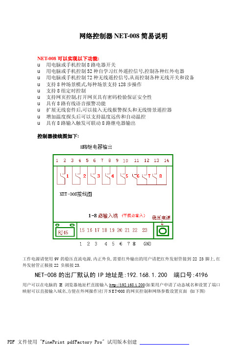
网络控制器NET-008简易说明NET-008可以实现以下功能:u用电脑或手机控制8路电器开关u用电脑或手机控制52种自学习红外遥控信号,控制各种红外电器u用电脑或手机控制72种无线遥控信号,从而控制各种无线开关和设备u支持8种场景模式,每种场景支持128步操作u支持8组定时控制u支持网页控制,打开网页具有密码检验保证安全性u具有8路有线语音报警功能u扩展无线套件后,可以接入无线报警探头和无线情景遥控器u增加温度探头后可以支持温度远传和自动温控u具有8路输入触发可联动8路继电器输出控制器接线图如下:工作电源请使用9V的稳压直流电源,内正外负,需要红外输出的用户请把红外发射管接到22 23脚上,红外发射管正极接22 负极接23.NET-008的出厂默认的IP地址是:192.168.1.200 端口号:4196用户可以在电脑的IE浏览器地址栏直接输入:http://192.168.1.200(如果用户申请了动态域名和设置了端口映射可以直接输入域名,方便在外网操作)打开NET-008的网页控制和网络参数设置页面(如下图)输入默认的网页进入密码123456 , 进入后将出现以下页面:如何修改NET-008的IP地址在网页下面的网络参数里可以修改NET-008的本地IP地址为用户想要的IP地址,最后[提交修改]修改完后关闭IE设置页面,打开NET-008专用客户端软件,打开客户端软件的菜单项[文件]à[系统设置]中填入以上设置的IP地址和端口号,如下图确定后,进行连接服务器.正常情况下连接成功后,软件左下端会出现提示,然后就可以用软件进行控制开关和红外了如果用户需修改输入输出属性,或者进行红外学习,在没有登录之前是按钮是灰色不可用的,只有登录后才可以用.如下图:初始出厂的登录密码是1234,用户可以在登录后重新修改此密码。
红外学习的操作:首先将按钮功能选择为学习的位置:如图然后可以点击52路中任何一路按钮(比如[第1路]按钮)开始红外学习,此时本来一闪一闪的绿灯会常亮,并且软件界面上会有如图的提示,说明进入了红外学习状态这时用户可以拿一个要学习的遥按器对准NET-008网络接口位置按一下需要学习的按键,比如空调的开机键,NET-008收到空调遥控器的开机信号后,常亮的绿色指示灯会熄灭,重新开始一闪一闪,软件界面上也会有提示:说明[第1路]按钮上已成功学习了红外空调开机键,如果用户长时间没有按遥控器的按钮,过一会软件上也会提示:这时用户可以重新学习,学习完毕后,用户可以把按钮功能选择为发送如图然后按下[第1路]按钮,NET-008的红外发射管就会发射学习到的空调开机信号,从而控制空调开机。

IE基础1.0动作分析1.1动作分析的目的与方法1.1.1动作分析的目的1) 动作的定义按工艺流程、作业和动作的顺序分析制造系统。
从投入原材料开始到成品为止的流程称为工艺流程。
一旦确定了工艺流程,紧接着要确定要一道工序最理想的作业方法。
在实施各种作业的时间,操作者身体的各个部位,如手、足、眼等有一个一个的活动。
在此,我们将动作定义为工艺流程和作业的具体实施方法,如为寻找、掘取、移动、装配必要的目的物、操作者身体各个部位的每个一个活动。
2) 动作分析动作分析的定义:按操作者实施的动作顺序观察动作,用特定的记号记录以手、眼为中心的人体各部位的动作内容,把握实际情况,并将上述记录图表化,以此为基础,判断动作的好坏,找出改善着眼点的一套分析方法。
通过对各种各样的作业不断地进行动作分析,可进入“在日常生产中不管对任何作业者抱有问题意识,仔细观察事物,判断动作的好坏,构思设计更好的动作顺序和方法”这样的境界。
这种境界称为动作意识。
对管理人员而言,具有动作意识是理所当然的事。
操作者也要培训出动作意识。
3) 动作分析的目的简单地讲,动作分析的目的是把握动作的现状,找出问题并加以改善,具体有以下几个方面:①了解操作者身体部位的动作顺序和方法;②了解以两手为中心的人体各部位是否能尽可能同时动作,是否相互联系;③明确各种动作的目的,动作过程中的必要动作和不必要动作;④了解必要的作业动作中两手的平衡。
1.1.2动作分析方法可以分类以下两大类:目视动作观察法、影像动作观察法。
基于目视动作观察的有动素分析和双手操作分析法,基于影像动作观察的对应于不同类型的作业有高速摄影分析(也称为细微动作影像分析)、常速摄影分析、慢速摄影分析及VTR 分析(也称为录相摄影分析)等。
下面简介其中常用的一种:动素分析,就是观察人体中的手、足动作和眼、头活动,把两手的动作顺序和方法与眼睛的各种活动联系起来,用18个描述动作最小单位的动素记号记录动作并加以分析的一种方法。
Windows 2008安装动易.NET系统之四----动易系统安装篇下面为动易.NET系统2.9以上版本的安装步骤。
/为网站地址。
第一步,打开IE,在地址栏里输入网站的地址(/default.aspx),打开后,如下图安装界面,勾选安装协议,然后点击“下一步”。
注意:当输入地址“/default.aspx”,如是初始安装,系统会自动跳到安装页面(/Install/Default.aspx)。
第二步,进入网站地址运行环境检测,以确认您的环境符合要求,如下图,全部通过即可继续下一步操作。
第三步,进行数据库连接设置,请先设置好数据库的登录帐号并建好数据库,并根据建好的帐号和数据库名填写表单中的项。
虚拟主机用户该部分信息会由主机供应商提供。
1、选择数据库版本,如您的是SQL SERVER2008 ,请选择“Sql Server 2005”;
2、输入正确的数据源;
3、输入正确的数据库名称;
4、输入正确的数据库用户称;
5、输入正确的数据库用户口令。
输入完毕后,点击下一步。
第四步,创建数据库。
单击“开始创建”,等待2~3分钟,请耐新等待,请不要刷新页面。
如下图:
第五步,创建数据库完成,点击下一步。
如下图:
第六步,配置网站相关信息。
输入相关配置信息,进入下一步操作。
(请牢记您的“管理员名称”和“管
理员密码”)
如下图:
第七步,安装完成,点击完成进入网站首页。
网站首页:(不同版本安装,首页会有所不同)
至此,安装完成,赶快使用吧,感谢使用动易系统。
This guide is applicable to ACQ80-01 drives, frames R4 and R5. Safety instructionsBefore you start the work, isolate the drive from all dangerous voltage sources and make sure that it is safe to start the work. Always wait for 5 minutes after disconnecting the input power to let the intermediate circuit capacitors discharge.•magnet motor energizes the drive, including its input and output terminals.•Frames R5: Do not tilt the drive. The drive is heavy and has a high center of gravity. It can topple accidentally.•Frames R5: Lift the drive with a lifting e the lifting eyes of the drive.1.Unpack the deliveryKeep the drive in its package until you are ready to install it. After unpacking, protect the drive from dust, debris and moisture. Make sure that these items are included:•cable box (frame R5, IP21 [UL Type 1])•drive•mounting template •control panel•quick installation and start-up guide•multilingual residual voltage warning stickers •hardware and firmware manuals, if ordered •options in separate packages, if ordered.Make sure that there are no signs of damage to the items.2.Reform the capacitorsIf the drive has not been powered up for a year or more, you must reform the DC link capacitors. Refer to Capacitorreforming instructions (3BFE64059629 [English]).3.Select the cables and fuses•Select the power cables. Obey the local regulations.•Input power cable: ABB recommends to use symmetrical shielded cable (VFD cable) for the best EMC performance. •Motor cable: Use symmetrical shielded cable (VFD cable) for the best EMC performance. Symmetrical shielded cable also reduces bearing currents, wear, and stress on motor insulation.•Power cable types: In IEC installations, use copper or aluminum cables (if permitted). In UL installations, use only copper cables.•Current rating: max. load current.•Voltage rating: min. 380 V AC.•Temperature rating: In IEC installations, select a cable rated for at least 70 °C (158 °F) maximum permissibletemperature of conductor in continuous use. In UL installations and for drives with option +B056 (IP55, UL Type 12),select a cable rated for at least 75 °C (167 °F).•Size: Refer to Ratings, fuses and typical power cable sizes for the typical cable sizes and to Terminal data for the power cables for the maximum cable sizes.•Select the control cables. Use double-shielded twisted-pair cable for analog signals. Use double-shielded or single-shielded cable for the digital, relay and I/O signals. Do not run 24V and 115/230V signals in the same cable.•Protect the drive and input power cable with the correct fuses. Refer to Ratings, fuses and typical power cable sizes .Documentation in other languagesEcodesign information (EU 2019/1781)About this document3AXD50001017217 Rev A EN2023-03-27© 2023 ABB. All rights reserved.Original instructions.—ABB DRIVES FOR WATERACQ80-01 (30 to 55 kW) drivesQuick installation and start-up guideR56. Remove the cover(s)7. Attach a residual voltage warning sticker to the drive in the local language 8. Make sure that the drive is compatible with the grounding systemYou can connect all drives to a symmetrically grounded TN-S system (center-grounded wye). If you install the drive to a different system, you must remove the EMC screw (disconnect the EMC filter) and/or remove the VAR screw (disconnect the varistor circuit).9. Measure the insulation of the power cables and the motorMeasure the insulation of the input cable before you connect it to the drive. Obey the local regulations.Measure the insulation of the motor cable and motor when the cable isdisconnected from the drive. Measure the insulation resistance between eachphase conductor and the PE conductor. Use a measuring voltage of 1000V DC. The insulation resistance of an ABB motor must be more than 100Mohm (reference value at 25°C [77°F]). For the insulation resistance of other motors, see the manufacturer’s instructions. Moisture inside the motor casing decreases theinsulation resistance. If you think that there is moisture inside the motor casing, dry the motor and do the measurement again.10. Connect the power cablesConnection diagram (shielded cables)Frame sizeSymmetrically grounded TN-S systems (center-grounded wye)Corner-grounded deltaand midpoint-grounded delta systems IT systems (ungrounded or high-resistance grounded)TT systems 1) 2)1) A residual current device must be installed in the supply system.2) ABB does not guarantee the EMC category or the operation of the ground leakage detector built inside the drive.R4…R5Do not remove EMC orVAR screw.Note: The drive is not evaluated for use on these systems by IEC standards.Remove EMC screws (2pieces) and VAR screw.Remove EMC screws (2pieces) and VAR screw.R4, IP21 (UL Type 1)2.EMI filter is optional but is mandatory for IEC/EN62920 standard compliance which is required in Europe.3.Ground connection should be common for MOV, drive, and pump.2.Prepare the power cables:•Remove the rubber grommets from the cable entry.•Cut a sufficient hole in the rubber grommet. Slide the grommet onto the cable (a).•Prepare the ends of the input power cable and motor cable as illustrated in the figure (b).•Slide the cables through the holes in the cable entry and attach the grommets to the holes.•If you use aluminum cables, apply grease to the stripped conductors before you connect them to the drive.3.Connect the power cables. For the tightening torques, refer to Terminal data for the power cables.•Connect the phase conductors of the motor cable to terminals T1/U, T2/V and T3/W. Connect the twisted shield of the cable to the grounding terminal. (a)•Connect the input power cable to terminals L1, L2 and L3. Connect the twisted shield of the cable and the additional PE conductor to the grounding terminal. (b)•Tighten the clamps of the power cable grounding shelf onto the stripped part of the cables (c). Torque the clamps to1.2N·m (10.6lbf·in).R3…R4 are similar.Make the connections according to the application. Keep the signal wire pairs twisted as near to the terminals as possible to prevent inductive coupling.1.Cut a hole into the rubber grommet and slide the grommet onto the cable.2.Ground the outer shield of the cable 360 degrees under the grounding clamp. Keep the cable unstripped as close to theterminals of the control unit as possible. Ground also the pair-cable shields and grounding wire at the SCR terminal. 3.Tie all control cables to the provided cable tie mounts.EIA-485 embedded fieldbus connectionYou can connect the drive to a serial communication link with a fieldbus adapter module or the embedded fieldbus interface. The embedded fieldbus interface supports the Modbus RTU protocol.To configure Modbus RTU communication with the embedded fieldbus:1.Connect the fieldbus cable and the required I/O signals.2.If the drive is at the end of the fieldbus, set the termination switch to ON.3.Power up the drive and set the required parameters. Refer to Fieldbus communication .Overview and connection diagrams for connecting the drive to the fieldbus are shown below.Tie shield conductors together at the drive. Do not terminate at SCR.• Terminate the shield only at terminal “G” (ground) in the automation controller.•Terminate DGND conductor at terminal “R” (reference) in the automation controller.12. Install optional modules, if included in the delivery13. Install the cover(s)The cover installation procedure is the opposite of the removal procedure. Refer to Remove the cover(s).14. Start up the driveON TERM ONBIASTermination ON ON TERM ONBIASTermination OFFON TERM ONBIASTermination OFF10Fieldbus communicationTo configure the embedded fieldbus communication for Modbus RTU, you must set at least these parameters:Other parameters related to the fieldbus configuration:Warnings and faultsRatings, fuses and typical power cable sizesParameterSetting Description20.01 Ext1 commands Embedded fieldbus Selects fieldbus as the source for the start and stop commands when EXT1 is selected as the active control location.22.11 Ext1 speed ref1EFB ref1Selects a reference received through the embedded fieldbus interface as speed reference 1. Use this parameter with the vector motor control mode.26.11 Torque ref1 source EFB ref1Selects a reference received through the embedded fieldbus interfaceas torque reference 1. Use this parameter with the vector motor control mode.28.11 Ext1 frequency ref1EFB ref1Selects a reference received through the embedded fieldbus interfaceas frequency reference 1. Use this parameter with the frequency motor control mode.58.01 Protocol enable Modbus RTU Initializes embedded fieldbus communication.58.03 Node address 1 (default)Node address. There must be no two nodes with the same nodeaddress online.58.04 Baud rate 19.2kbps (default)Defines the communication speed of the link. Use the same setting asin the master station.58.05 Parity8 EVEN 1 (default)Selects the parity and stop bit setting. Use the same setting as in themaster station.58.14 Communication loss action58.17 Transmit delay 58.28 EFB act1 type 58.34 Word order 58.15 Communication loss mode58.25 Control profile 58.31 EFB act1 transparent source58.101 Data I/O 1 …58.114 Data I/O 1458.16 Communication loss time58.26 EFB ref1 type58.33 Addressing modeWarning Fault Aux. codeDescriptionA2A12281Current calibration Warning: Current calibration is done at the next start.Fault: Output phase current measurement fault.A2B12310Overcurrent The output current is more than the internal limit. This can also be caused by an earth fault or phase loss.A2B32330Earth leakage A load unbalance that is typically caused by an earth fault in the motor or the motor cable.A2B42340Short circuit There is a short-circuit in the motor or the motor cable.-3130Input phase loss The intermediate DC circuit voltage oscillates due to missing input power line phase.-3181Wiring or earth fault Incorrect input and motor cable connection.A3A13210DC link overvoltage Intermediate DC circuit voltage is too high.A3A23220DC link undervoltage Intermediate DC circuit voltage is too low.-3381Output phase loss All three phases are not connected to the motor.-5090STO hardware failure STO hardware diagnostics has detected hardware failure. Contact ABB.A5A05091Safe torque off The Safe torque off (STO) function is active.A7CE 6681EFB comm lossBreak in embedded fieldbus communication.A7C17510FBA A communication Communication lost between drive (or PLC) and fieldbus adapter.A7AB -Extension I/Oconfiguration failure The installed C-type module is not the same as configured, or there is an error in the communication between the drive and module.AFF6-Identification run The motor ID run occurs at the next start.-FA81Safe torque off 1The Safe torque off circuit 1 is broken.-FA82Safe torque off 2The Safe torque off circuit 2 is broken.ACQ80-01-…Nominal ratingsFusesTypical power cable sizes, Cu Frame sizeInput currentNominal Idc Output currentMotor power 1)1) Typical motor power with no overload capacity (nominal use). The kilowatt ratings apply to most IEC 4-pole motors. The horsepower ratings apply to most NEMA 4-pole motors.gG fuse(IEC 60269)DC MCBsI 1I IDC I NP NABB typeAAkW hp mm 2U N =3-phase 400V or 480V 030kW-46250.78623040OFAF000H80S802PV-S633×25 + 16R4037kW-47359.79733750OFAF000H100T1D/PV 160 4p F FCCu 1100V DC 3×35 + 16R4045kW-48872.07884560OFAF000H100T1D/PV 160 4p F FCCu 1100V DC 3×50 + 25R5055kW-410686.811065575OFAF00H125T1D/PV 160 4p F FCCu 1100V DC3×70 + 35R5Terminal data for the power cablesNotes:• The minimum specified wire size does not necessarily have sufficient current carrying capacity at maximum load.• The terminals do not accept a conductor that is one size larger than the maximum specified wire size.• The maximum number of conductors per terminal is 1.Weights and free space requirementsThis table shows the requirements for the ambient conditions when the drive is in operation (installed for stationary use).Ambient conditionsSafe torque off (STO)The drive has a Safe torque off function (STO) in accordance with IEC/EN 61800-5-2. It can be used, for example, as the final actuator device of safety circuits that stop the drive in case of danger (such as an emergency stop circuit).When activated, the STO function disables the control voltage of the power semiconductors of the drive output stage, thus preventing the drive from generating the torque required to rotate the motor. The control program generates an indication as defined by parameter 31.22. If the motor is running when Safe torque off is activated, it coasts to a stop. Closing the activation switch deactivates the STO. Any faults generated must be reset before restarting.The STO function has a redundant architecture, that is, both channels must be used in the safety function implementation.•If stopping by coasting is not acceptable, stop the drive and machinery using the appropriate stop mode before activating the STO.•The STO function overrides all other functions of the drive.⏹WiringThe safety contacts must open/close within 200ms of each other.Double-shielded twisted-pair cable is recommended for the connection. The maximum length of the cabling between the switch and the drive control unit is 300m (1000 ft). Ground the shield of the cable at the control unit only.⏹ValidationTo ensure the safe operation of a safety function, a validation test is required. The test must be carried out by a competent person with adequate expertise and knowledge of the safety function. The test procedures and report must bedocumented and signed by this person. Validation instructions of the STO function can be found in the drive hardware manual.Frame size T1/U, T2/V, T3/W, L1, L2, L3, R-, R+/UDC+PEMin. wire size (solid/stranded)Max. wire size (solid/stranded)Tightening torqueMax. wire size (solid/stranded)Tightening torque mm 2AWG mm 2AWG N·m lbf·ft mm 2AWG N·m lbf·ft R40.5/0.520501 4.0 3.035/3521.51.1R5610702/0 5.6 4.1-Frame sizeWeightsFree space requirements for vertical installationStand alone Side by side 1)1) Without free space on the sides.IP21 (UL Type 1)IP55 (UL Type 12)IP21 (UL Type 1)IP55 (UL Type 12)All types All typesAbove Below 2)2) Measured from the drive frame, not from the cable box.Above Below 2)Sides Above Below 2)kg lb kg lb mm in mm in mm in mm in mm in mm in mm in R419.041.920.044.153 2.12007.953 2.02007.9150 5.92007.92007.9R528.362.429.064.0100 4.02007.9100 4.02007.9150 5.92007.92007.9Installation altitude0…4000m (0…13123 ft) above sea level. The output current must be derated at altitudes above 1000m (3281ft). The derating is 1% for each 100m (328ft) above 1000m (3281ft).Above 2000m (6562ft), these grounding systems are permitted: TN-S (center-grounded wye), TT, and IT (ungrounded or high-resistance symmetrically grounded). For the installation requirements for corner-grounded systems at this altitude, contact your local ABB representative.Surrounding air temperature -15…+50°C (5…122°F). No frost permitted. The rated output current must be derated by 1% for each 1°C (1.8°F) above 40°C (104°F).Relative humidity 5…95%. No condensation permitted. Maximum permitted relative humidity is 60% in the presence of corrosive gases.Contamination levels (IEC 60721-3-3: 2002)Chemical gases: Class 3C2.Solid particles: Class 3S2. No conductive dust permitted.Vibration (IEC 60068-2)Max. 1mm (5 … 13.2Hz), max. 7m/s 2 (13.2 … 100Hz) sinusoidal Shock/Drop (ISTA)Not permittedTechnical data•Minimum voltage at IN1 and IN2 to be interpreted as “1”: 13V DC•STO reaction time (shortest detectable break): 1 ms•STO response time: 2 ms (typical), 5 ms (maximum)•Fault detection time: Channels in different states for longer than 200 ms•Fault reaction time: Fault detection time + 10 ms•STO fault indication (parameter 31.22) delay: < 500 ms•STO warning indication (parameter 31.22) delay: < 1000 ms•Safety integrity level (EN62061): SIL3•Performance level (EN ISO 13849-1): PL eThe drive STO is a type A safety component as defined in IEC61508-2.For the full safety data, exact failure rates and failure modes of the STO function, refer to the drive hardware manual. MarkingsThe applicable markings are shown on the type designation label of the drive.Related documentsDeclaration of ConformityCE ROHS RCM WEEE TÜV NordDocument Code (English)ACQ80-01 (30 kW to 55 kW) Drive HW manual3AXD50001017101 ACQ80 standard control program firmware manual3AXD50000170654 ACx-AP-x assistant control panels user’s manual3AUA0000085685 Drive Composer PC tool user's manual3AUA0000094606EU Declaration of ConformityMachinery Directive 2006/42/ECWeManufacturer: ABB India LimitedAddress: Plot No 5 &6 , 2 Phase , Peenya Industrial Area ,Bangalore,560058, IndiaPhone: +91 80 22949359Declare under our sole responsibility that the following product:Frequency converterACQ80ACQ80-04 (frame sizes R0-R3) and ACQ80-01 (frame sizes R4-R5)with regard to the safety functionSafe torque-offis in conformity with all the relevant safety component requirements of the EU Machinery Directive2006/42/EC, when the listed safety function is used for safety component functionality.The following harmonized standards have been applied:EN 61800-5-2:2007 Adjustable speed electrical power drive systems –Part 5-2: Safety requirements - FunctionalEN 62061:2021 Safety of machinery – Functional safety of safety-related electrical,electronic and programmable electronic control systemsEN ISO 13849-1:2015 Safety of machinery – Safety-related parts of control systems.Part 1: General principles for designEN ISO 13849-2:2012 Safety of machinery – Safety-related parts of the control systems.Part 2: ValidationEN 60204-1:2018 Safety of machinery – Electrical equipment of machines –Part 1: General requirementsThe following other standard has been applied:IEC 61508:2010, parts 1-2 Functional safety of electrical / electronic / programmableelectronic safety-related systemsIEC 61800-5-2:2016 Adjustable speed electrical power drive systems –Part 5-2: Safety requirements - FunctionalThe product referred in this declaration of conformity fulfils the relevant provisions of otherEuropean Union directives which are notified in a single EU declaration of conformity3AXD10000715392.Person authorized to compile the technical file 3AXD10000715648:Name and address: Jussi Vesti, Hiomotie 13, 00380 Helsinki, FinlandBangalore, 15 March 2023Signed for and on behalf of:AR MadhusudhanVice President, MODPABB India LimitedLaxmikantha shenoyManager , Prodcut EngineeringABB India Limited。