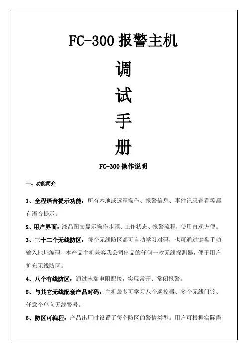
神港FC系列说明书
- 格式:pdf
- 大小:2.80 MB
- 文档页数:32
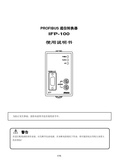
PROFIBUS通信转换器IFP-100使用说明书警告在进行配线或检查作业前,应先断开仪表电源。
在未断电的情况下作业,将可能因电击导致人身重大伤害事故!IFP-1001. 简介1.1 IFP-100简介------------------------------------------------------------------------------- 3 1.2 系统配置----------------------------------------------------------------------------------- 32. 型号2.1 型号----------------------------------------------------------------------------------------- 3 2.2 型号铭牌的表示方法-------------------------------------------------------------------- 33.各部位名称和功能--------------------------------------------------------------- 34. 设定------------------------------------------------------------------------------- 45. 安装5.1 场所选择----------------------------------------------------------------------------------- 5 5.2 外形尺寸图-------------------------------------------------------------------------------- 5 5.3 圆形插座安装----------------------------------------------------------------------------- 66. 导线连接6.1 接线端排列-------------------------------------------------------------------------------- 7 6.2 导线连接实例----------------------------------------------------------------------------- 77. 通信数据7.1数据形式------------------------------------------------------------------------------------ 9 7.2数据结构------------------------------------------------------------------------------------ 9 7.3数据设定过程-------------------------------------------------------------------------------- 12 7.4读数据过程-------------------------------------------------------------------------------- 12 7.5数据传送------------------------------------------------------------------------------------- 128. 规格--------------------------------------------------------------------------------- 139. 故障排除--------------------------------------------------------------------------141. 简介1.1 IFP-100简介IFP-100 是一种通信转换器,用来连接PROFIBUS主机单元(SIEMENS PLC,等),作为PROFIBUS-DP从机单元,进行数据交换。
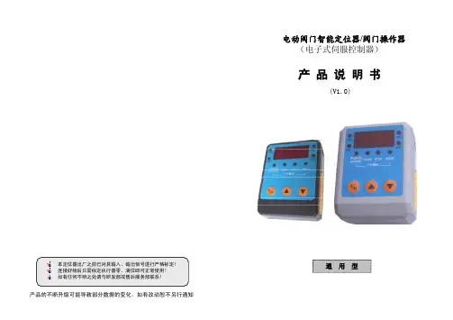
产品的不断升级可能导致部分数据的变化,如有改动恕不另行通知电动阀门智能定位器/阀门操作器(电子式伺服控制器)产 品 说 明 书(V1.0)通 用 型目录一、 概述 (1)二、 电气性能指标 (1)三、 主要技术指标 (2)四、 操作显示面板 (3)五、 接线方法 (4)六、 产品使用方法 (5)七、 产品输入输出信号标定 (6)八、 出厂恢复与辅助设置 (7)九、 错误代码列表 (8)十、 用户软件操作流程图 (8)符-oh-。
U5等于-oh-状体下才能进入到U6、U7手动转角标定。
当U5在数字密码状态时,按下键递减数据,可回到-oh-状态。
当按住▲或▼键不动时,数据以恒定的速度快速递增和递减。
U0-U13按▲或▼键修改设置参数堵转测试:当发给执行器动作指令时,若在xx.x 秒都没有动作,将发出-E4-(或-E5-)错误代码,并停止xx.x 秒后,向动作指令的反方向动作2秒,然后再向动作指令的方向动作xx.x 秒,若故障消除,则清除错误代码且解除报警状态,继续工作。
若没有解除,则再停止xx.x 秒后,向动作指令的反方向动作2秒,然后再向动作指令的方向动作xx.x 秒。
如此往复动作3回合,都没有消除故障,则永远出现-E4-(或-E5-)错误代码和报警,等待人为断电故障排查。
3、故障报警:当产品有报警接口,且出现故障代码时,报警继电器由常开转为常闭。
代码消失,报警继电器恢复常开,完全与故障代码同步。
注意:无效回差时间(传动误差)较大时,应将堵转时间设定大些避免误报警!执行器电机连接线脱接、过热保护、执行器传动齿轮间隙大、电位器安装时传动齿轮之间间隙大、电位器脱接或质量不良等因素,都会产生堵转处理程序,所以出现此故障,请先排查执行器问题。
补充说明:1、U0-U4菜单的功能可在线调试,可定位器处于自动控制状态,当某参数发生改变时,定位器能根据新参数实时调控。
2、在U5菜单时,U5与-oh -交替显示。
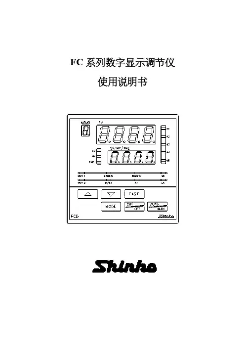
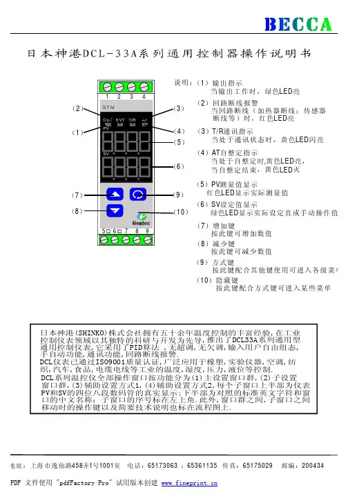
日本神港JC-33A系列通用控制器操作说明书日本神港(SHINKO)株式会社拥有五十余年温度控制的丰富经验,在工业控制仪表领域以其独特的科研与开发为先导,推出了JC-33A系列通用型通用控制仪表,它采用了最先进的加热冷却双PID算法,无超调,无欠调,输入用户自由组态,双设定值,手自动功能,通讯功能,回路断线报警,JC系列仪表已通过ISO9001质量认证,广泛应用于橡胶,实验仪器,空调,纺织,汽车,食品,电缆电线等工业的温度,湿度,压力,液位元等控制。
(1)PV测量值显示 (9)TX/RX通讯指示红色LED显示实际测量值 当处于通讯状态时,黄色LED亮(2)SV设定值显示 (10)A1报警1指示 绿色LED显示实际设定值或手动输出值 当报警1动作时,红色LED亮(3)设定值1指示 (11)A2/L2报警指示当使用设定值1时,绿色LED亮 当报警2动作或回路断线时,(4)设定值2显示 红色LED亮当使用设定值2时,黄色LED亮 (12)增加键(5)输出1指示 按此键增加数值当输出1工作时,绿色LED亮 (13)减少键(6)输出2指示 按此键减少数值当输出2工作时,黄色LED亮 (14)方式键(7)HB加热器断线报警 按此键并配合其它键使用可进入各级菜单当发生加热器断线或传感器断线时, (15)OUT/OFF键红色LED亮 按此键一秒钟可关闭仪表输出 ;(8)AT自整定指示 按三秒钟可输出百分比当处于自整定状态时,黄色LED亮(1) 仪表选型JC □- □ 3 A- □/ M, □JC SERIES D JCD (W96×H96×D100mm ) R JCR (W48×H96×D100mm ) 尺寸 SJCS (W48×H48×D100mm ) 1适用于JCD ,JCR 机种 序 号 2仅适用于JCS-23-A □/□机种 控制动作 3PID 控制(控制方式可以选择) 警报1(A1) A多种动作系统(动作方式可选择) RRelay 继电器接点,1a 1b (JCS:1a) SDC 电压输出(驱动SSR 用):12+20V 控制输出(O U T ) ADC 电流输出:4~20mA M多种范围输入系统(输入种类热电偶、电阻体可选择) ADC 电流输入:0~20mA ,4~20mA (JCS 可于M 入力中选择此入力) 入 力 V DC 电压输入:0~1V ,0~10V ,1~5V(JCS 可于M 入力中选择0~1V )A2 警报2(A2)(动作方式可选择) W(5A)等级:5A W(10A)等级:10AW(20A)等级:20AW(50A)加热器 断线警报 等级:50A DR Relay 继电器接点:1aDS DC 电压输出(驱动SSR 用): 12+20V 最大40mA DA 控制输出 加热、 冷却控制 (JCS 无)DC 电流输出:4~20mA 负荷电阻:最大550ΩC5 串行通信 RS-485LA 回路断线警报SM 设定值记忆外部切换功能(仅JCS 为附加特殊功能)BK 黑色IP 防尘·防滴(IP54)特殊功能(需指定) TC 外壳接线端子防护<注>:特殊功能并非每一机种均可指定采用,请参照各别机种详细目录。

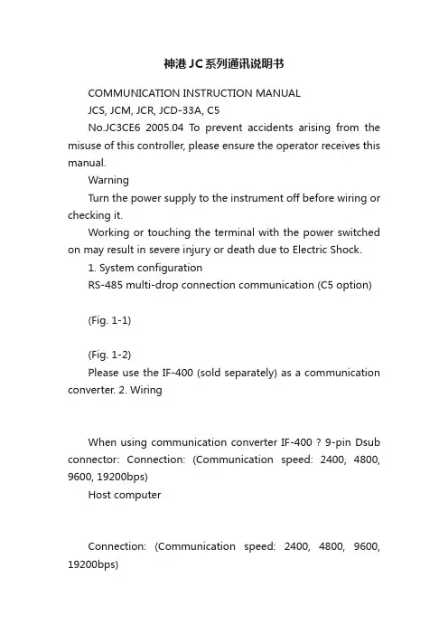
神港JC系列通讯说明书COMMUNICATION INSTRUCTION MANUALJCS, JCM, JCR, JCD-33A, C5No.JC3CE6 2005.04 To prevent accidents arising from the misuse of this controller, please ensure the operator receives this manual.WarningTurn the power supply to the instrument off before wiring or checking it.Working or touching the terminal with the power switched on may result in severe injury or death due to Electric Shock.1. System configurationRS-485 multi-drop connection communication (C5 option) (Fig. 1-1)(Fig. 1-2)Please use the IF-400 (sold separately) as a communication converter. 2. WiringWhen using communication converter IF-400 ? 9-pin Dsub connector: Connection: (Communication speed: 2400, 4800, 9600, 19200bps)Host computerConnection: (Communication speed: 2400, 4800, 9600, 19200bps)Shield wireConnect only one side of the shield wire to the FG terminal so that current cannot flow to the shield wire.(If both sides of the shield wire are connected to the FG terminal, the circuit will be closed between the shield wire and the ground. As a result, current will run through the shield wire and this may cause noise.)Be sure to ground the FG terminal. Terminator (Terminal resistor)Do not connect terminator with the communication line because each JC -33A has built-in pull-up and pull-down resistors instead of a terminator.-33AIt is necessary to set the instrument number individually to the JC -33A when communicating byconnecting plural units in serial communication (C5 option).Select a communication speed of the JC -33A in accordance with that of the host computer. ? For the instrument number setting and communication speed, refer to the instruction manual for JC -33A.4. Communication procedureCommunication starts with command transmission from the host computer (hereafter Master) and ends with the response of the JC -33A (hereafter Slave).Response with datathe master sends the reading command, the slaveresponds with the corresponding set value or current ?Acknowledgementthe master sends the setting command, the slaveresponds by sending the acknowledgement after theprocessing is terminated. ? Negative acknowledgement the master sends non-existent command or value out of the setting range, the slave returns the negative ? No responseaddress is set, or when there is a communication error(framing error or checksum error), or when LRC or CRCdiscrepancy is detected.Host computerCommunication timing of the RS-485 (C5 option)Slave sideWhen the slave starts transmission through RS-485 communication line, the slave is arranged so as to provide an idle status (mark status) transmission period of 1 or more characters before sending the response to ensure the synchronization on the receiving side.The slave is arranged so as to disconnect the transmitter from the communication line within a1 character transmission period after sending the response.Master side (Notice on programming)Set the program so that the master can disconnect the transmitter from the communication line withina 1 character transmission period after sending the command in preparation for reception of theresponse from the slave.To avoid the collision of transmissions between the master and the slave, send the next command after carefully checking that the master received the response.5. Shinko protocol5.1 Transmission modeShinko protocol is composed of ASCII codes.Hexadecimal (0 to 9, A to F), which is divided into high order (4-bit) and low order (4-bit) out of 8-bit binary data in command is transmitted as ASCII characters.Data format Start bit : 1 bitData bit : 7 bitsP arity : EvenS top bit : 1 bitError detection: Checksum5.2 Command configurationAll commands are composed of ASCII. The data (set value, decimal number) is represented withhexadecimal number, and ASCII code is used.The negative numbers are represented with 2's complement.(1) Setting command(2) Reading command(3) Response with data(5) Negative acknowledgementHeader: Control code to represent the beginning of the command or the response.ASCII codes are used.Setting command, Reading command : 02H fixedResponse with data, Acknowledgement : 06H fixedNegative acknowledgement : 15H fixed Number ofcharactersNumber ofcharactersNumber ofcharacters Number ofcharactersNumber ofcharactersAddress (Instrument number): Numbers by which the master discerns each slave. Instrument number 0 to 94 (00H to 5EH) and Global address 95 (7FH) The numbers (20H to 7EH) are used by giving 20H of bias, because 00H to 1FH are used for control code.95 (7FH) is called Global address , which is used when the same command is sent to all the slaves connected. However, the response is not returned.Sub address : 20H fixedCommand type : Code to discern Setting command (50H) and Reading command (20H) Data item : Data classification of the command object Composed of hexadecimal 4 digits (Refer to the Communication command table) Data : The contents of data (set value) depend on the setting command Composed of hexadecimal 4 digits (Refer to the Communication command table) Checksum : 2-character data to detect communication errors Delimiter : Control code to represent the end of command 03H fixed Error code : Represents an error type. Composed of hexadecimal 1 digit. 1 (31H)-----Non-existent command 2 (32H)-----Not used 3 (33H)-----Setting outside the setting range 4 (34H)-----Status unable to set (e.g. AT is performing) 5 (35H)-----During setting mode by keypad operation5.3 Checksum calculationChecksum is used to detect receiving errors in the command or data.Set the program for the master side as well to calculate the checksum of the response data from the slaves so that the communication errors can be checked. The ASCII code (hexadecimal) corresponding to the characters which range from the address to that before the checksum is converted to binary notation, and the total value is calculated.The lower 2-digit of the total value are converted to 2’s complements, and then to hexadecimal figures, that is, ASCII code for the checksum. Refer to the following example procedure. Checksum calculation example Main set value: 600 (0258H) Address (instrument number): 0 (20H)1’s complement: Reverse each binary bit. 0 will become 1 and vice ve rsa. ? 2’s complement: Add 1 to 1’s complements.20H50H0010 00000101 00001101 11111+[1's complement][2's complement][Hexadecimal][ASCII]5.4 Contents of the commandNotes on the setting command and reading commandPossible to set the set value by setting command of the communication function even when the set value is locked.Although the options are not applied, setting the items forthe options is possible by the setting command. However, they will not function.The memory can store up to 1,000,000 (one million) entries.If the number of settings exceeds the limit, the data will not be saved. So frequent transmission via communication is not recommended.When connecting plural slaves, the address (instrument number) must not be duplicated.When sending a command by Global address [95 (7FH)], the same command is sent to all the slaves connected. However, the response is not returned.The instrument number and communication speed of the slave cannot be set by communication function.Setting commandThe settable range is the same as that by key operation.For the communication command, refer to the communication command table of this manual. ? All commands are composed of ASCII.The data (set value, decimal) is converted to hexadecimal figures, and ASCII is used.A negative number is represented by 2's complement. When the data (set value) has a decimal point, a whole number without a decimal point is used. Reading commandAll commands are composed of ASCII.The data (set value, decimal) is converted to hexadecimal figures, and ASCII is used.A negative number is represented by 2's complement. When the data (set value) has a decimal point, the response is returned as a whole number without a decimal point.6. Modbus protocol6.1 Transmission modeThere are 2 transmission modes (ASCII and RTU) in Modbus protocol. 6.2 ASCII modeHexadecimal (0 to 9, A to F), which is divided into high order (4-bit) and low order (4-bit) out of 8-bit binary data in command is transmitted as ASCII characters. Data format Start bit : 1 bit Data bit : 7 bits P arity : Even/Odd/No parity (Selectable) S top bit : 1 bit/2 bits (Selectable) Error detection : LRC (Longitudinal Redundancy Check) Data interval : 1 second or less (1) Message configurationASCII mode message is configured to start by [: (colon)(3AH)] and end by [CR (carriage return) (0DH) + LF (Line feed)(0AH)]. (See Fig. 6.2-1)(2) Slave addressSlave address is an individual instrument number on the slave side and is set within the range 00H to 5FH (0 to 95).The master identifies slaves by the slave address of the requested message.The slave informs the master which slave is responding to the master by placing its own address in the response message.[Slave address 00H (broadcast address) can identify all the slaves. However slaves do not respond.] (3) Function code The function code is the command code for the slave to undertake the following action types (T able 6.2-1). (Table 6.2-1) Function code Contents 03 (03H) Reading the set value and information from slaves 06 (06H) Setting to slavesFunction code is used to discern whether the response is normal (acknowledgement) or if any error (negative acknowledgement) is occurred when the slave returns the response message to the master. When acknowledgement isreturned, the slave simply returns the original function code.When negative acknowledgement is returned, the MSB of the original function code is set as 1 for the response.Slave address FunctioncodeDataError check LRC Delimiter (CR)Header (:)Delimiter (LF)(For example, when the master sends request message setting 10H to function code by mistake, slave returns 90H by setting the MSB to 1, because the former is an illegal function.) For negative acknowledgement, exception code (Table 6.2-2) below is set to the data of response message and returned to the master in order to inform it that what kind of error has occurred. (Table 6.2-2)Exception code Contents1 (01H) Illegal function (Non-existent function)2 (02H) Illegal data address (Non-existent data address)3 (03H)Illegal data value (Value out of the setting range)17 (11H)Illegal setting (Unsettable status)18 (12H) Illegal setting (During setting mode by key operation, etc)(4) DataData depends on the function code.A request message from the master is composed of data item, number of data and setting data.A response message from the slave is composed of numberof bytes, data and exception codein negative acknowledgement. Effective range of data is –32768 to 32767 (8000H to 7FFFH).(5) Error check of ASCII modeAfter calculating LRC (Longitudinal Redundancy Check) from the slave address to the end of data, the calculated 8-bit data is converted to two ASCII characters and are appended to the end of message.Create a message in RTU mode.Add all the values from the slave address to the end of data. This is assumed as X.Make a complement for X (bit reverse). This is assumed as X.Add a value of 1 to X. This is assumed as X.Set X as an LRC to the end of the message.Convert the whole message to ASCII characters.Reading (Instrument number 1, SV)A request message from the masterThe number of data means the data item to be read, and it is fixed as (30H 30H 30H 31H).A response message from the slave in normal status (When SV=100)(Fig.6.2-3) The number of response bytes means the number of bytes of the data which has been read,and it is fixed as (30H 32H).A response message from the slave in exception (error) status (When data item is mistaken)The function code MSB is set to 1 for the response message in exception (error) status (83H).The exception code (02H: Non-existent data address) isreturned as contents of error.Setting (Instrument number 1, SV=100)A request message from the master(Fig.6.2-5)A response message from the slave in normal status(Fig.6.2-6)SlaveaddressFunctioncodeData itemError checkLRCDelimiterHeader(30H 31H)Number ofdata(3AH)1224422(30H 33H)(30H 30H 30H 31H)(30H 30H 30H 31H)(46H 41H)(0DH 0AH)Number of charactersSlaveaddressFunctioncodeNumber ofresponse bytesError checkLRCDelimiterHeader Data1222422(3AH)(30H 31H)(30H 33H)(30H 32H)(30H 30H 36H 34H)(39H 36H)(0DH 0AH)Number ofcharacters(0DH 0AH)SlaveaddressFunctioncodeExceptioncodeError checkLRCDelimiterHeader122222Number ofcharacters(3AH)(30H 31H)(38H 33H)(30H 32H)(37H 41H)SlaveaddressFunctioncodeData itemError checkLRCDelimiterHeader(30H 31H)Data(3AH)1224422Number ofcharacters(30H 36H)(30H 30H 30H 31H)(30H 30H 36H 34H)(39H 34H)(0DH 0AH)SlaveaddressFunctioncodeData itemError checkLRCDelimiter Header Data1224422Number ofcharacters (3AH)(30H 31H)(30H 36H)(30H 30H 30H 31H)(30H 30H 36H 34H)(39H 34H)(0DH 0AH)A response message from the slave in exception(error) status (When a value out of the setting range is set)(Fig. 6.2-7)The function code MSB is set to 1 for the response message in exception (error) status (86H). The exception code (03H: Value out of the setting range) is returned as contents of error.6.3 RTU mode8-bit binary data in command is transmitted as it is. Data format Start bit : 1 bit Data bit : 8 bits Parity : Even/Odd/No parity (Selectable) Stop bit : 1 bit/2 bits (Selectable) Error detection : CRC-16 (Cyclic Redundancy Check) Data interval : 3.5 characters transmission time or less (1) Message configurationRTU mode is configured to start after idle time is processed for more than 3.5 character transmission and end after idle time is processed for more than 3.5 character transmission. (See Fig.6.3-1) (Fig. 6.3-1) (2) Slave addressSlave address is an individual instrument number on the slave side and is set within the range 00H to 5FH (0 to 95).The master identifies slaves by the slave address of the requested message.The slave informs the master which slave is responding to the master by placing its own address in the response message.[Slave address 00H (broadcast address) can identify all the slaves. However slaves do not respond.] (3) Function code The function code is the command code for the slave to undertake the following action types (T able 6.3-1). (Table 6.3-1) Function code Contents 03 (03H) Reading the set value and information from slaves 06 (06H) Setting to slavesFunction code is used to discern whether the response is normal (acknowledgement) or if any error (negative acknowledgement) is occurred when the slave returns the response message to the master. When acknowledgement is returned, the slave simply returns the original function code.When negative acknowledgement is returned, the MSB of the original function code is set as 1 for the response.(For example, when the master sends request message setting 10H to function code by mistake, slave returns 90H bysetting the MSB to 1, because the former is an illegal function.) For negative acknowledgement, exception code (Table 6.3-2) below is set to the data of response message and returned to the master in order to inform it that what kind of error has occurred. (Table 6.3-2)Exception code Contents 1 (01H) Illegal function (Non-existent function) 2 (02H) Illegal data address (Non-existent data address) 3 (03H) Illegal data value (Value out of the setting range) 17 (11H) Illegal setting (Unsettable status) 18 (12H) Illegal setting (During setting mode by keypad operation, etc) (4) Data Data depends on the function code.A request message from the master side is composed of data item, number of data and setting data. A response message from the slave side is composed of number of bytes, data and exception code in negative acknowledgement. Effective range of data is –32768 to 32767 (8000H to 7FFFH). (5) Error check of RTU modeAfter calculating CRC-16 (Cyclic Redundancy Check) from the slave address to the end of data, the calculated 16-bit data is appended to the end of message in sequence from low order to high order.3.5 idle characters Slave address Function codeData Error check CRC 3.5 idlecharacters Slave addressFunction codeException codeError checkLRCDelimiterHeader2Number ofcharacters 22221(3AH)(30H 31H)(38H 36H)(30H 33H)(37H 36H)(0DH 0AH)How to calculate CRCIn the CRC system, the information is divided by the polynomial series. The remainder is added to the end of the information and transmitted. The generation of polynomial series is as follows.16 + X 15+ X 2 + 1)Initialize the CRC-16 data (assumed as X) (FFFFH).Calculate exclusive OR (XOR) with the 1st data and X. This is assumed as X.Shift X one bit to the right. This is assumed as X.When a carry is generated as a result of the shift, XOR is calculated by X ofand the fixeduntil shifting 8 times.up to the last data.Set X as CRC-16 to the end of message in sequence from low order to high order. RTU modeReading (Instrument number 1, SV) ? Request message from the masterThe number of data means the data item to be read, and it is fixed as 0001H. ? Response message from the slave in normal status (When SV=100)(Fig. 6.3-3)The number of response byte means number of bytes of the data which has been read, and it is fixed as 02H.Response message from the slave in exception (error) status (When non-existent data item is sent)The function code MSB is set to 1 for the response message in exception (error) status (83H). The exception code (02H: Non-existent data address) is returned as contents of error. Setting (Instrument number 1, SV=100) ? Request message from the masterResponse message from the slave in normal statusResponse message from the slave in exception (error) status (When a value out of the setting range is set)The function code MSB is set to 1 for the response message in exception (error) status (86H). The exception code (03H: Value out of the setting range) is returned as contents of error.3.5 idle charactersSlave address Function code Data itemError check CRC 3.5 idle characters(01H)(03H)(0001H)Number of data (0001H)(D5CAH)11222Number of characters3.5 idle charactersSlave address Function code Number of response bytesError check CRC 3.5 idle characters(01H)(03H)(02H)Data(0064H)(B9AFH)11122characters3.5 idle charactersSlave address Function code Exception code Error check CRC 3.5 idle characters(01H)(83H)(02H)(C0F1H)1112Number of characters3.5 idle charactersSlave address Function code Data item Error check CRC 3.5 idle characters(01H)(06H)(0001H)Data (0064H)(D9E1H)11222characters 3.5 idle charactersSlave address Function code Data item Error check CRC 3.5 idle characters(01H)(06H)(0001H)Data(0064H)(D9E1H)112223.5 idle characters Slave address Function code Exception code Error check CRC 3.5 idle characters(01H)(86H)(03H)(0261H)1112characters7. Communication command tableWhen the data (set value) has a decimal point, remove the decimal point and represent it as a whole number, then express it in hexadecimal figures.Shinko command type ModbusfunctioncodeData item Data20H/50H 03H/06H 0001H: SV1 Set value20H/50H 03H/06H 0002H: Not used20H/50H 03H/06H 0003H: AT/Auto-reset setting 0000H: Cancel 0001H: Perform 20H/50H 03H/06H 0004H: OUT1 proportional band setting Set value20H/50H 03H/06H 0005H: OUT2 proportional band setting Set value20H/50H 03H/06H 0006H: Integral time setting Set value20H/50H 03H/06H 0007H: Derivative time setting Set value 20H/50H 03H/06H 0008H: OUT1 proportional cycle setting Set value20H/50H 03H/06H 0009H: OUT2 proportional cycle setting Set value20H/50H 03H/06H 000AH: Not used20H/50H 03H/06H 000BH: A1 setting Set value20H/50H 03H/06H 000CH: A2 setting Set value20H/50H 03H/06H 000DH: Not used20H/50H 03H/06H 000EH: Not used20H/50H 03H/06H 000FH: HB (Heater burnout alarm)settingSet value20H/50H 03H/06H 0010H: LA (Loop break alarm) timesettingSet value20H/50H 03H/06H 0011H: LA (Loop break alarm) spansettingSet value20H/50H 03H/06H 0012H: Set value lock selection (*1) 0000H: Unlock 0001H: Lock 10002H: Lock 2 0003H: Lock 3 20H/50H 03H/06H 0013H: SV high limit setting Set value20H/50H 03H/06H 0014H: SV low limit setting Set value20H/50H 03H/06H 0015H: Sensor correction value setting Set value20H/50H 03H/06H 0016H: Overlap/Dead band setting Set value20H/50H 03H/06H 0017H: Not used20H/50H 03H/06H 0018H: Scaling high limit setting Set value 20H/50H 03H/06H 0019H: Scaling low limit setting Set value 20H/50H 03H/06H 001AH: Decimal point place selection 0000H: XXXX (No decimal point)0001H: XXX.X (1 digit after decimalpoint)0002H: XX.XX (2 digits after decimalpoint)0003H: X.XXX (3 digits after decimalpoint)20H/50H 03H/06H 001BH: PV filter time constant setting Set value20H/50H 03H/06H 001CH: OUT1 high limit setting Set value 20H/50H 03H/06H 001DH: OUT1 low limit setting Set value 20H/50H 03H/06H 001EH: OUT1 ON/OFF actionhysteresis settingSet value20H/50H 03H/06H 001FH: OUT2 action mode selection 0000H: Air cooling0001H: Oil cooling0002H: Water cooling20H/50H 03H/06H 0020H: OUT2 high limit setting Set value 20H/50H 03H/06H 0021H: OUT2 low limit setting Set value 20H/50H 03H/06H 0022H: OUT2 ON/OFF action hysteresis settingSet value20H/50H 03H/06H 0023H: A1 action selection (*2)0024H: A2 action selection (*2) 0000H: No alarm action0001H: High limit alarm0002H: Low limit alarm0003H: High/Low limits alarm 0004H: High/Low limit range alarm 0005H: Process high alarm0006H: Process low alarm0007H: High limit alarm with standby 0008H: Low limit alarm with standby 0009H: H/L limits alarm w/standby[–200 to 1370400.0[–200 to 1000176017601820800400.013001390[0 to 2315[–199.9 to 850.0[–199.9 to 500.08505002500750.0[–320 to 1800320033001500750.023002500[0 to 4200[–199.9 to 999.9[–199.9 to 900.0[–300 to 15009004 to 20mA DC[–1999 to 9999]20H/50H 03H/06H 0048H: ARW (anti-reset windup) settingSet value20H/50H 03H/06H 006FH: Key Lock selection 0000H:Key enabled0001H: Key Lock50H 06H0070H:Key operation change flagclearing 0000H:No action 0001H: All clearing20H 03H 0080H: PV reading Present PV (input value)20H 03H 0081H: OUT1 MV reading Set value20H 03H 0082H: OUT2 MV reading Set value20H 03H 0083H: Not used20H 03H 0084H: Not used20H 03H 0085H: OUT status reading 0000 0000 0000 0000 215to 2020 digit: OUT10: OFF 1: ON21 digit: OUT20: OFF 1: ON22digit: A1 output0: OFF 1: ON23 digit: A2 output0: OFF 1: ON24 digit: Not used (Always 0)25 digit: Not used (Always 0)26 digit: HB (Heater burnout alarm)output0: OFF 1: ON(When sensor burnout, 0: OFF)27 digit: LA (Loop break alarm)output0: OFF 1: ON28 digit: Overscale0: OFF 1: ON29 digit: Underscale0: OFF 1: ON210 digit: OUT/OFF selection0: OUT 1: OFF211 digit: AT/Auto-reset0: OFF 1: ON212 digit: OUT/OFF key functions election0: OUT/OFF 1: Auto/Manual213 digit: Not used (Always 0)214 digit: Auto/Manual control0: Automatic 1: Manual215 digit: Change in key operation0: No 1: Yes20H 03H 0086H: Not used20H 03H 0087H: Not used20H 03H 00A0H: Not used20H 03H 00A1H: Instrument information reading 0000 0000 0000 0000215to 2020 digit: Not used (Always 0)21 digit: Cooling action0: Not applied 1: Applied22 digit: A1 function0: Not applied 1: Applied23 digit: A2 function0: Not applied 1: Applied24 digit: Not used (Always 0)25 digit: Not used (Always 0)26 digit: HB (Heater burnout alarm)0: Not applied 1: Applied27 digit: LA (Loop break alarm)0: Not applied 1: Applied28 to 215 digit: Not used (Always 0)This is why the set value reverts to the one before Lock 3 when power is turned OFF.(*2) When alarm action type is changed, the alarm set value reverts to the default value and alarm output status is also initialized.NoticeWhen data setting is changed by front keypad operation, the data that is related to the changed item is also changed automatically as shown in Example 1 below.However, when the data setting is changed by communication function, the related data does not change as shown in Example 2 below. (Only the changed data is altered.) (Example 1) SV high limit: 1370SV: 1000When SV high limit is changed to 800 by the front keypad operation, both SV high limit and SV are changed to 800.(Example 2) SV high limit: 1370SV: 1000When SV high limit is changed to 800 by communication function, SV high limit is changed to 800, however, SV ismaintained at the same temperature 1000.8. SpecificationsC able length : Maximum communication distance 1.2km Cable resistance: Within 50 (Terminator is not necessary or 120 or more on one side.)Communication line : EIA RS-485 Communication method : Half-duplexCommunication speed : 9600bps (2400, 4800, 9600, 19200bps) Selectable by keypad Synchronous system : Start-stop synchronous Code form : ASCII, binary Error correction : Command request repeat system Error detection : Parity check, Checksum (LRC), CRC Data format Start bit : 1 Data bit : 7, 8 Parity : Even, Odd, No parity Stop bit : 1, 29. TroubleshootingIf any malfunctions occur, refer to the following items after checking the power supply to the master and the slave.Problem: Communication failureCheck the followingThe connection or wiring of communication cable is not secure.Burnout or imperfect contact on the communication cable and the connector. Communication speed of the slave does not coincide with that of the master.The data bit, parity and stop bit of the master do not accord with those of the slave. The instrument number of the slave does not coincide with that of the command. The instrument numbers are duplicated in multiple slaves.Make sure that the program is appropriate for the transmission timing.Problem: Although communication is occurring, the response is 'NAK'.Check the followingCheck that a non-existent command code has not been sent.The setting command data exceeds the setting range of the slave.The controller cannot be set when functions such as AT are performing. The operation mode is under the front keypad operation setting mode.For further inquiries, please consult our agency or the shop where you purchased the unit.SHINKO TECHNOS CO.,LTD.OVERSEAS DIVISION::::Reg. Office Mail Address URL E-mail1-2-48, Ina, Minoo, Osaka, Japan P.O.Box 17, Minoo, Osaka, Japan http://www.shinko-technos.co.jp overseas@shinko-technos.co.jpTel :Fax:81-72-721-278181-72-724-1760。

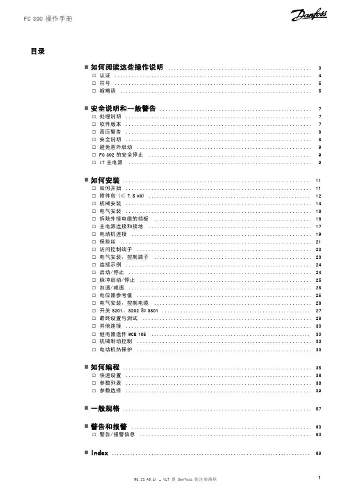
FC系列中文操作说明
欢迎使用FC系列(神港)智能设备!本操作说明将教您如何正确使
用该设备并获取最佳的使用体验。
请您仔细阅读并依照说明进行操作。
部件介绍:
1.电源按钮:通过按下此按钮,可以打开或关闭设备的电源。
2.电源指示灯:显示设备的电源状态,绿色表示设备开启,红色表示
设备关闭或处于待机状态。
3.屏幕:设备的显示屏幕,用于显示设备的各种信息和操作界面。
4.功能按钮:设备上配备了几个功能按钮,根据每个设备的不同,按
钮的功能也有所不同。
详细信息请参考设备的操作说明书。
B接口:用于连接设备和外部设备的USB接口,可以方便地进行
数据传输和设备充电。
操作流程:
1.打开设备电源:长按电源按钮约3秒钟,直到电源指示灯变为绿色,表示设备已开启。
2.屏幕操作:设备开启后,屏幕将显示主界面。
通过触摸屏幕上不同
的图标和按钮,可以进入不同的功能菜单和操作界面。
3.功能选择:根据您的需要,从主界面中选择相应的功能菜单或操作
选项。
在屏幕上通过触摸和滑动,您可以进行不同的操作和设置。
常见问题解答:
1.一开机电池就耗尽怎么办?
2.设备无法开启怎么办?
3.如何连接设备和外部设备?
答:请将外部设备的USB插头插入设备的USB接口,并确保连接稳定。
设备会自动检测并显示外部设备的相关信息。
4.如何进行设备的固件升级?
5.如何进行数据备份和恢复?
答:请使用设备附带的数据备份工具并按照界面提示完成备份和恢复
操作。
更多详细操作,请参考设备的操作说明书。
MICRO-COMPUTER BASED DIGITAL INDICATING CONTROLLERACS-13AINSTRUCTION MANUALPrefaceThank you for purchasing of our microcomputer based digital indicating controller ACS-13A. This manual contains instructions for the mounting, functions, operations and notes when operating the ACS-13A. To prevent accidents arising from the misuse of this controller, please ensure the operator receives this manual.Characters used in this manual :Number,/ -1 0 1 2 3 4 5 6 7 8 9IndicationAlphabet A B C D E F G H I J K L MIndicationAlphabet N OP Q RSTUVWXY Z IndicationNotes• This instrument should be used in accordance with the specifications described in the manual.If it is not used according to the specifications, it may malfunction or cause fire.• Be sure to follow the warnings, cautions and notices. If they are not observed, serious injury or malfunction may occur. • The contents of this instruction manual are subject to change without notice.• Care has been taken to assure that the contents of this instruction manual are correct, but if there are any doubts, mistakes or questions, please inform our sales department.• This instrument is designed to be installed within a control panel. If it is not, measures must be taken to ensure that the operator cannot touch power terminals or other high voltage sections. • Any unauthorized transfer or copying of this document, in part or in whole, is prohibited.• Shinko Technos CO., LTD. is not liable for any damage or secondary damage(s) incurred as a result of using this product, including any indirect damage.Safety precautions (Be sure to read these precautions before using our products.)The safety precautions are classified into categories: “Warning” and “Caution”. Depending on circumstances, procedures indicated by Caution may be linked to serious results, so be sure to follow the directions for usage.WarningWarning• To prevent an electric shock or fire, only Shinko or qualified service personnel may handle the inner assembly. • To prevent an electric shock, fire or damage to the instrument, parts replacement may only be undertaken by Shinko or qualified service personnel.• To ensure safe and correct use, thoroughly read and understand this manual before using this instrument.Caution with respect to Export Trade Control OrdinanceT o avoid this instrument from being used as a component in, or as being utilized in the manufacture of weapons of mass destruction (i.e. military applications, military equipment, etc.), please investigate the end users and the final use of this instrument. In the case of resale, ensure that this instrument is not illegally exported.Procedures which may lead to dangerous conditions and cause death or serious injury, if not carried out properly .Procedures which may lead to dangerous conditions and cause superficial to medium injury or physical damage or may degrade or damage the product, if not carried out properly.1. Installation precautionsCautionThis instrument is intended to be used under the following environmental conditions(IEC61010-1): Overvoltage category , Pollution degree 2Ensure the mounting location corresponds to the following conditions:• A minimum of dust, and an absence of corrosive gases• No flammable, explosive gases• No mechanical vibrations or shocks• No exposure to direct sunlight, an ambient temperature of 0 to 50(32 to 122) that does not change rapidly, and without icing• An ambient non-condensing humidity of 35 to 85%RH• No large capacity electromagnetic switches or cables through which large current is flowing.• No water, oil or chemicals or where the vapors of these substances can come into direct contact with the unitNote • Do not install this instrument near flammable material even though the case of this instrument is made of flame-resistant resin.Avoid setting this instrument directly on flammable material.2. Wiring precautionsCaution• Do not leave bits of wire in the instrument, because they could cause fire or malfunction.• Use the solderless terminal with an insulation sleeve in which the M3 screw fits when wiring the ACS-13A.• The terminal block of this instrument is designed to be wired from the left side.The lead wire must be inserted from the left side of the terminal, and fastened with the terminal screw.• Tighten the terminal screw to within the specified torque. If excessive force is applied to thescrew when tightening, the terminal screw or case may be damaged.• When using a terminal cover, pass terminal wires numbered 7 to 12 into the holes of the terminal cover.• This instrument does not have a built-in power switch, circuit breaker or fuse.It is necessary to install them near the controller.(Recommended fuse: Time-lag fuse, rated voltage 250V AC, rated current 2A)• For a 24V AC/DC power source, do not confuse polarity when using direct current (DC).• Do not apply a commercial power source to the sensor which is connected to the input terminal nor allow the power source to come into contact with the sensor.• Use a thermocouple and compensating lead wire according to the sensor input specifications of this controller.• Use the 3-wire RTD according to the sensor input specifications of this controller.• (+) side input terminal number of 0 to 5V DC, 1 to 5V DC, 0 to 10V DC differs from that of 0 to 1V DC.(+) side input terminal number of 0 to 5V DC, 1 to 5V DC, 0 to 10V DC: 9(+) side input terminal number of 0 to 1V DC: 10• When using a relay contact output type, externally use a relay according to the capacity of the load to protect the built-in relay contact.• When wiring, keep input wires (thermocouple, RTD, etc.) away from AC sources or load wires to avoid external interference.3. Operation and maintenance precautionsCaution• It is recommended that PID auto-tuning be performed on the trial run.• Do not touch live terminals. This may cause electric shock or problems in operation.• Turn the power supply to the instrunment OFF when retightening the terminal or cleaning.Working or touching the terminal with the power switched ON may result in severe injury or death due to Electric Shock.• Use a soft, dry cloth when cleaning the instrument.(Alcohol based substances may tarnish or deface the unit.)• As the display section is vulnerable, do not strike or scratch it with a hard object or press hard on it.ContentsPage 1. Model -------------------------------------------------------------------------------------- 51.1 Model ---------------------------------------------------------------------------------- 51.2 How to read the model label ----------------------------------------------------- 52. Name and functions of the sections ------------------------------------------- 63. Mounting to the control pane l ---------------------------------------------------- 73.1 External dimensions (Unit: mm) ------------------------------------------------ 73.2 Panel cutout (Unit: mm) ---------------------------------------------------------- 73.3 CT (Current transformer) external dimensions (Unit: mm) --------------- 73.4 Mounting and removal to/from the control panel ---------------------------- 84. Wiring ------------------------------------------------------------------------------------- 94.1 Terminal arrangement ------------------------------------------------------------- 94.2 Lead wire solderless terminal ---------------------------------------------------- 94.3 Terminal cover ---------------------------------------------------------------------- 104.4 Heater burnout alarm output (W, W3option) wiring ----------------------- 105. Operation flowchart ---------------------------------------------------------------- 116. Setup ------------------------------------------------------------------------------------ 126.1 Turn the power supply to the ACS-13A ON -------------------------------- 126.2 Basic key operations ------------------------------------------------------------- 126.3 Setup mode ------------------------------------------------------------------------ 137. Settings -------------------------------------------------------------------------------- 207.1 Main setting mode ---------------------------------------------------------------- 207.2 Sub setting mode ----------------------------------------------------------------- 217.3 Auxiliary function setting mode ------------------------------------------------ 238. Running ------------------------------------------------------------------------------- 248.1 Starting operation ----------------------------------------------------------------- 248.2 Control output OFF function ---------------------------------------------------- 258.3 Auto/Manual control switching ------------------------------------------------- 258.4 Indicating output MV ------------------------------------------------------------- 268.5 Auto-tuning/Auto-reset Perform/Cancel ------------------------------------- 269. Auto-reset ----------------------------------------------------------------------------- 2610. Auto-tuning ---------------------------------------------------------------------------- 2711. Action explanation ------------------------------------------------------------------ 2811.1 OUT1 action ---------------------------------------------------------------------- 2811.2 OUT1 ON/OFF action ---------------------------------------------------------- 2811.3 Heater burnout alarm action -------------------------------------------------- 2911.4 Alarm action ---------------------------------------------------------------------- 2911.5 OUT2 (Heating/Cooling control) action ----------------------------------- 3011.6 OUT2 (Heating/Cooling control) action (When setting Dead band) ----- 3011.7 OUT2 (Heating/Cooling control) action (When setting Overlap band) -- 3112. Specifications ------------------------------------------------------------------------ 3212.1 Standard specifications -------------------------------------------------------- 3212.2 Optional specifications --------------------------------------------------------- 3513. Troubleshooting --------------------------------------------------------------------- 3713.1 Indication -------------------------------------------------------------------------- 3713.2 Key operation -------------------------------------------------------------------- 3813.3 Control ----------------------------------------------------------------------------- 3814 Character table ----------------------------------------------------------------------- 391. Model 1.1 ModelS Non-contact voltage (for SSR drive): 12V DC15%AInput M1Non-contact voltage: 12V DC15%*1: Alarm types (9 types and No alarm action) and Energized/Deenergized can be selected by keypad.*2: Thermocouple, RTD, DC current and DC voltage can be selected by keypad.For DC current input, connect 50shunt resistor (sold separately) externally.*3: Supply voltage 100 to 240V AC is standard. When ordering 24V AC/DC, enter “1” after the input code.1.2 How to read the model labelThe model label is attached to the left side of the case.For Heater burnout alarm output, CT rated current is written in the bracket.(1): Model, Power supply (For 24V AC/DC, “1” is entered), Options(2): Serial number(e.g.)Relay contact output/Multi-range input(Fig.1.2-1)(2)2. Name and functions of the sections(Fig. 2-1)Display (1) PV indicator : Lights when PV is indicated in the PV/SV display mode. (2) PV display : Indicates the PV (process variable). (3) SV indicator : Lights when SV is indicated in the PV/SV display mode.(4) MEMO indicator : Lights when Set value memory external selection (SM option) is added. (5) MEMO display : Indicates the set value memory number. (6) SV display : Indicates the SV (Main set value). (7) Action indicators O1 (OUT1) : Lights when control output is ON or when Heating output (D option) is ON. For DC current output type, flashescorresponding to the MV in 0.25 second cycles.O2 (OUT2) : Lights when cooling output (D option) is ON. EV1 : Lights when Alarm 1 output is ON. EV2 : Lights when Alarm 2 output (A2 option) is ON or when Heater burnout alarm (W, W3 option) is ON. AT : Flashes while AT (auto-tuning) or auto-reset is performing. T/R : Lights during Serial communication (C5 option) (TX output).LOCK : Lights when Lock 1, Lock 2 or Lock 3 is selected.Key operations (8) Increase key : Increases the numeric value. (9) Decrease key : Decreases the numeric value. (10) Mode key : Selects the setting mode, or registers the set value. To register the set (selected) value, press this key.(11) OUT/OFF key : Switches control output ON/OFF or Auto/Manual control.To release the control output ON/OFF, press this key for approx. 1sec.(12) Console connector :By connecting to the USB communication cable (CMA, sold separately), the following operations can be conducted from the external computer using the Console software SWS-ACS01M. • Reading and setting of SV, PID and various set values• Reading of PV and action status • Function change(10)(11)3. Mounting to the control panel3.1 External dimensions (Unit: mm)(Fig. 3.1-1)3.2 Panel cutout(Unit: mm)CautionIf lateral close mounting is used for the controller, IP66 specification (Dust-proof/Drip-proof) may be compromised, and all warranties will be invalidatedLateral close mountingn: Number of units mounted(Fig. 3.2-1)3.3 CT (Current transformer) external dimensions (Unit: mm)CTL-6S (for 20A) CTL-12-S36-10L1 (for 50A)(Fig. 3.3-1)754545+0.5045+0.50n x 48-3+0.50(*) When a terminal cover (sold separately) is used.3.4 Mounting and removal to/from the control panelCautionAs the mounting frame is made of resin, do not use excessive force while tightening screws, or the mounting frame could be damaged.Tighten screws with one rotation upon the screw tips touching the panel. The torque is approximately 0.05 to 0.06 N•m.How to mount the ACS-13AMount the controller vertically to the flat, rigid panel to ensure it adheres to the Dust-proof/Drip-proof specification (IP66).Mountable panel thickness: Within 1 to 5mm(1) Insert the controller from the front side of the panel. (Fig.3.4-1)(2) Insert the unit until mounting frame comes into contact with the panel, and fasten with the screw. Tighten screws with one rotation upon the screw tips touching the panel. (Fig.3.4-2) The torque is approximately 0.05 to 0.06N•m.(Fig.3.4-1)How to remove the mounting frame and unit (Fig. 3.4-3)(1) Turn the power to the unit OFF, and disconnect all wires before removing the mounting frame. (2) Insert a flat blade screwdriver between the screw frame and unit (3) Slowly push the frame upward using the screwdriver (4) Repeat step (2) and slowly push the frame downward using the screwdriver for the other side.The frame can be removed little by little by repeating these steps.(Fig.3.4-3)(Fig.3.4-2)Mounting frame4. WiringWarningTurn the power supply to the instrument off before wiring or checking.Working or touching the terminal with the power switched on may result in severe injury or death due to Electric Shock.4.1 Terminal arrangement(Fig. 4-1) • POWERSUPPLY: For a 24V AC/DC power source, do not confuse polarity when using direct current (DC). • EV1 : Alarm 1 output • O2/EV2: Cooling output (D option), Alarm 2 output (A2 option) or Heater burnout alarm output (W, W3 option) • O1 : Control output or Heating output (D option) • DC : DC current, DC voltage input(For DC voltage input, + side terminal number differs depending on the voltage input.) (+) side input terminal number of 0 to 5V DC, 1 to 5V DC, 0 to 10V DC: 9(+) side input terminal number of 0 to 1V DC: 10• TC : Thermocouple input• RTD : Resistance temperature detector input • CT1 : CT input 1 (W, W3 option) • CT2 : CT input 2 (W3 option) • DI : Contact input (SM option) • RS-485 : Serial communication RS-485 (C5 option)4.2 Lead wire solderless terminalUse a solderless terminal with an insulation sleeve in which an M3 screw fits as shown below. The torque is approximately 0.6N•m to 1.0N•m. Solderless terminal Manufacturer ModelTighteningtorqueNichifu T erminal Industries CO.,LTD. 1.25Y -3Y typeJapan Solderless T erminal MFG CO.,LTD.VD1.25-B3A Nichifu T erminal Industries CO.,LTD.1.25-3 Round type Japan Solderless T erminal MFG CO.,LTD. V1.25-30.6N•mMax. 1.0N•m(Fig. 4.2-1)POWER SUPPLY+ 3A 250V AC 3A250V AC + DI2DI1COM YA(-)YB(+)SG DI RS-4853A 250VAC + +++DC 0 to 1V 4 to 20mA 0 to 20mADC4.3 Terminal coverWhen using a terminal cover (sold separately), pass terminal wires numbered 7 to 12 into the holes of the terminal cover.(Fig. 4.3-1)4.4 Wiring Heater burnout alarm output (W, W3 option)This alarm is not usable for detecting heater current under phase control.Use the CT (current transformer) provided, and pass one lead wire of the heater circuit into the hole of the CT. (Fig. 4.4-1).When wiring, keep the CT wire away from AC sources or load wires to avoid the external interference.(Fig. 4.4-1)In the case of 3-phase (W3 option), pass any 2 lead wires of R, S, T into the CT, and connect them with CT1 (13, 14) and CT2 terminals (14, 15). (Fig.4.4-2)Pass any 2 wires of R, S and T into CT.(Fig. 4.4-2)RS T5. Operation flowchartPower ONControl output OFF/Manual control Control output OFF (Approx. 1sec) Auto/Manual control PV/SV display mode (Automatic control)For 3 seconds after the power is turned on, the PV display indicates the input type, and the SV display indicates input range high limit value (TC, RTD) or scaling high limit value (DC voltage, DC current). (Approx. 3sec) Output MV indication[Main setting mode] SV+ [Sub setting mode] Auto-tuning/ Auto-reset+ (Approx. 3sec) [Auxiliary function setting mode] Set value lock+ (Approx. 3sec) [Setup mode] Input typeAlarm 1 hysteresisSV2OUT1 proportional band OUT2 proportional band Integral timeSensor correctionScaling high limitAlarm 2 hysteresisSV3Communication protocolScaling low limitAlarm 1 action delayed timerSV4Instrument numberDecimal point placeAlarm 2 action delayed timerDerivative timeCommunication speedPV filter time constantSV rise rateARWData bit/ParityOUT1 high limitSV fall rateOUT1 proportional cycle OUT2 proportional cycle Alarm 1 valueStop bitOUT1 low limitDirect/Reverse control actionOUT1 ON/OFF action hysteresisAT biasOUT2 action modeSVTC biasAlarm 2 valueOUT2 high limitContact input functionHeater burnout alarm value (*1) Heater burnout alarm 2 value (*2)OUT2 low limitOutput status selection when input abnormal OUT/OFF key functionOverlap band/ Dead bandOUT2 ON/OFF action hysteresisBacklightAlarm 1 typePV color[Key operation]• • • • + + : Press the key while pressing the key. (Approx.3sec): Press the key for approx. 3 seconds while holding down the key. + (Approx.3sec): Press the key for approx. 3 seconds while holding down the key. : This means that if the (MODE) key is pressed, the unit proceeds to the next setting mode.Alarm 2 type PV color rangeAlarm 1 Energized/ Deenergized Alarm 2 Energized/ DeenergizedBacklight time[Setting item]• PV display indicates setting item characters, and SV display indicates default value. (*1) CT1 current value and character are indicated alternately. (*2) CT2 current value and characters are indicated alternately. • Setting items with dotted lines (shaded) are optional, and they appear only when the options are added.Indication selection when output OFF OUT1 rate of change limit116. SetupSetup should occur before using this controller, to set the Input type, Alarm type, Control action, etc. according to the users’ conditions. Default values: Input (K, -200 to1370 ), Alarm 1 (No alarm action), Reverse (Heating) action If the users’ specification is the same as the default value of the ACS-13A, it is not necessary to set up the controller. Proceed to Chapter “7. Settings”. 6.1 Turn the power supply to the ACS-13A ON. After the power is turned on, the PV display indicates the input type, and the SV display indicates the input range high limit value (thermocouple, RTD input) or scaling high limit value (DC input) for approximately 3 seconds. (Table 6.1-1) During this time, all outputs and the indicators are in OFF status. Control will then start indicating the PV (process variable) on the PV display and SV (main set value) on the SV display. . While control output OFF function is working, the PV display indicates (Indication depends on the selection during “Output status selection when input abnormal”.) (Table 6.1-1) Sensor input K J R S B E T N PLC (W/Re5-26) Pt100 JPt100 4 to 20mA DC 0 to 20mA DC 0 to 1V DC 0 to 5V DC 1 to 5V DC 0 to 10V DC PV display SV display PV display SV displayScaling high limit value6.2 Basic key operations To enter each setting mode, refer to respective setting modes. or key, then register the value with the To set or select each setting item, use thekey.126.3 Setup mode To enter the Setup mode, press the PV/SV display mode. Characterkey for approx. 3 seconds while holding down thekey in theName, Function, Setting range Default value Input type selection K (-200 to 1370 ) • The input type can be selected from thermocouple (10 types), RTD (2 types), DC current (2 types) and DC voltage (4 types), and the unit / can be selected as well. • When changing the input from DC voltage to other inputs, remove the sensor connected to this controller first, then change for the input. If the input is changed with the sensor connected, the input circuit may break. • (+) side input terminal number of 0 to 5V DC, 1 to 5V DC, 0 to 10V DC differs from that of 0 to 1V DC. (+) side input terminal number of 0 to 5V DC, 1 to 5V DC, 0 to 10V DC: 9 (+) side input terminal number of 0 to 1V DC: 10 K -320 to 2500 K -200 to 1370K J R S B E T N PLC(W/Re5-26) Pt100 JPt100 Pt100 JPt100 4 to 20mA DC0 to 20mA DC-200.0 -200 0 0 0 -200 -200.0 -200 0 0 -200.0 -200.0 -200 -200 -2000to 400.0 to 1000 to 1760 to 1760 to 1820 to 800 to 400.0 to 1300 to 1390 to 2315 to 850.0 to 500.0 to 850 to 500 to 10000K -320.0 to 750.0 J -320 to 1800 R 0 to 3200 S 0 to 3200 B 0 to 3300 E -320 to 1500 T -320.0 to 750.0 N -320 to 2300 PL0 to 2500 C(W/Re5-26) 0 to 4200 Pt100 -320.0 to 1500.0 JPt100 Pt100 JPt100 -320.0 to 900.0 -320 to 1500 -320 to 900-2000 to 10000 0 to 1V DC -2000 to 10000 0 to 5V DC -2000 to 10000 1 to 5V DC -2000 to 10000 0 to 10V DC -2000 to 10000 Scaling high limit setting 1370 • Sets scaling high limit value. • Setting range: Scaling low limit value to input range high limit value DC voltage, current input: -2000 to 10000 (The placement of the decimal point follows the selection.) Scaling low limit setting -200 • Sets scaling low limit value. • Setting range: Input range low limit value to scaling high limit value DC voltage, current input: -2000 to 10000 (The placement of the decimal point follows the selection.) Decimal point place selection No decimal point • Selects decimal point place. Available only for DC input : No decimal point • : 1 digit after decimal point : 2 digits after decimal point : 3 digits after decimal point 13PV filter time constant setting 0.0 seconds • Sets PV filter time constant. If the value is set too large, it affects control result due to the delay of response. • Setting range: 0.0 to 10.0 seconds OUT1 high limit setting 100% • Sets the high limit value of OUT1. Not available if OUT1 is ON/OFF action • Setting range: OUT1 low limit value to 100% (DC current output type: OUT1 low limit value to 105%) OUT1 low limit setting 0% • Sets the low limit value of OUT1. Not available if OUT1 is ON/OFF action. • Setting range: 0% to OUT1 high limit value (DC current output type: -5% to OUT1 high limit value) OUT1 ON/OFF action hysteresis setting 1.0 • Sets ON/OFF action hysteresis for OUT1. Available only when OUT1 is ON/OFF action • Setting range: 0.1 to 100.0 ( ), DC voltage, current input: 1 to 1000 (The placement of the decimal point follows the selection.) OUT2 action mode selection Air cooling • Selects OUT2 action from air, oil and water cooling. Not available if the D option is not added or if OUT2 is ON/OFF action Air cooling (linear characteristic) • Oil cooling (1.5th power of the linear characteristic) Water cooling (2nd power of the linear characteristic)OUT2 proportional band Air cooling Oil cooling Water cooling SV setting(Fig. 6.3-1) OUT2 high limit setting 100% • Sets OUT2 high limit value. Not available if the D option is not added or if OUT2 is ON/OFF action • Setting range: OUT2 low limit value to 100% OUT2 low limit setting 0% • Sets OUT2 low limit value. Not available if the D option is not added or if OUT2 is ON/OFF action • Setting range: 0% to OUT2 high limit value Overlap band/Dead band setting 0.0 • Sets the overlap band or dead band for OUT1 and OUT2. + Set value: Dead band, –Set value: Overlap band Available only when the D option is added • Setting range: -100.0 to 100.0 ( ), DC voltage, current input: -1000 to 1000 (The placement of the decimal point follows the selection.) OUT2 ON/OFF action hysteresis setting 1.0 • Sets ON/OFF action hysteresis for OUT2. Available when the D option is added, and when OUT2 is ON/OFF control action. • Setting range: 0.1 to 100.0 ( ), DC voltage, current input: 1 to 1000 (The placement of the decimal point follows the selection.)14Alarm 1 type selection No alarm action • Selects an Alarm 1 type. (Refer to “11.4 Alarm action” on p.29.) : No alarm action : High limit alarm : Low limit alarm : High/Low limits alarm : High/Low limit range alarm : Process high alarm : Process low alarm : High limit alarm with standby : Low limit alarm with standby : High/Low limits alarm with standby Alarm 2 (A2) type selection No alarm action • Selects an Alarm 2 type. (Refer to “11.4 Alarm action” on p.29.) Available only when Alarm 2 (A2) option is added • Selection items are the same as those of Alarm 1. Alarm 1 Energized/Deenergized selection Energized • Selects Energized/Deenergized status for Alarm 1. (See p.18.) Not available if No alarm action is selected during Alarm 1 type selection : Energized • : Deenergized Alarm 2 Energized/Deenergized selection Energized • Selects Energized/Deenergized status for Alarm 2. (See p.18.) Not available if Alarm 2 (A2) option is not added or if No alarm action is selected during Alarm 2 type selection • Selection items are the same as those of Alarm 1 Energized/Deenergized selection. Alarm 1 hysteresis setting 1.0 • Sets hysteresis for Alarm 1. Not available if No alarm action is selected during Alarm 1 type selection • Setting range: 0.1 to 100.0 ( ), DC voltage, current input: 1 to 1000 (The placement of the decimal point follows the selection.) Alarm 2 hysteresis setting 1.0 • Sets hysteresis for Alarm 2. Not available if Alarm 2 (A2) option is not added or if No alarm action is selected during Alarm 2 type selection • Setting range: 0.1 to 100.0 ( ), DC voltage, current input: 1 to 1000 (The placement of the decimal point follows the selection.) Alarm 1 action delayed timer setting 0 seconds • Sets action delayed timer for Alarm 1. When setting time has elapsed after the input enters the alarm output range, the alarm is activated. Not available if No alarm action is selected during Alarm 1 type selection • Setting range: 0 to 10000 seconds Alarm 2 action delayed timer setting 0 seconds • Sets action delayed timer for Alarm 2. When setting time has elapsed after the input enters the alarm output range, the alarm is activated. Not available if Alarm 2 (A2) option is not added or if No alarm action is selected during Alarm 2 type selection • Setting range: 0 to 10000 seconds 15。
COMMUNICATION INSTRUCTION MANUALJCS, JCM, JCR, JCD-33A, C5No.JC3CE6 2005.04 To prevent accidents arising from the misuse of this controller, please ensure the operator receives this manual.WarningTurn the power supply to the instrument off before wiring or checking it.Working or touching the terminal with the power switched on may result in severe injury or death due to Electric Shock.1. System configurationRS-485 multi-drop connection communication (C5 option)(Fig. 1-1)(Fig. 1-2)Please use the IF-400 (sold separately) as a communication converter. 2. WiringWhen using communication converter IF-400 • 9-pin Dsub connector: Connection: (Communication speed: 2400, 4800, 9600, 19200bps)Host computerConnection: (Communication speed: 2400, 4800, 9600, 19200bps)Shield wireConnect only one side of the shield wire to the FG terminal so that current cannot flow to the shield wire.(If both sides of the shield wire are connected to the FG terminal, the circuit will be closed between the shield wire and the ground. As a result, current will run through the shield wire and this may cause noise.)Be sure to ground the FG terminal. Terminator (Terminal resistor)Do not connect terminator with the communication line because each JC -33A has built-in pull-up and pull-down resistors instead of a terminator.-33A• It is necessary to set the instrument number individually to the JC -33A when communicating byconnecting plural units in serial communication (C5 option).Select a communication speed of the JC -33A in accordance with that of the host computer. • For the instrument number setting and communication speed, refer to the instruction manual for JC -33A.4. Communication procedureCommunication starts with command transmission from the host computer (hereafter Master) and ends with the response of the JC -33A (hereafter Slave).• Response with datathe master sends the reading command, the slaveresponds with the corresponding set value or current • Acknowledgementthe master sends the setting command, the slaveresponds by sending the acknowledgement after theprocessing is terminated. • Negative acknowledgement the master sends non-existent command or value out of the setting range, the slave returns the negative • No responseaddress is set, or when there is a communication error(framing error or checksum error), or when LRC or CRCdiscrepancy is detected.Host computerCommunication timing of the RS-485 (C5 option)Slave sideWhen the slave starts transmission through RS-485 communication line, the slave is arranged so as to provide an idle status (mark status) transmission period of 1 or more characters before sending the response to ensure the synchronization on the receiving side.The slave is arranged so as to disconnect the transmitter from the communication line within a1 character transmission period after sending the response.Master side (Notice on programming)Set the program so that the master can disconnect the transmitter from the communication line withina 1 character transmission period after sending the command in preparation for reception of theresponse from the slave.To avoid the collision of transmissions between the master and the slave, send the next command after carefully checking that the master received the response.5. Shinko protocol5.1 Transmission modeShinko protocol is composed of ASCII codes.Hexadecimal (0 to 9, A to F), which is divided into high order (4-bit) and low order (4-bit) out of 8-bit binary data in command is transmitted as ASCII characters.Data format Start bit : 1 bitData bit : 7 bitsP arity : EvenS top bit : 1 bitError detection: Checksum5.2 Command configurationAll commands are composed of ASCII. The data (set value, decimal number) is represented withhexadecimal number, and ASCII code is used.The negative numbers are represented with 2's complement.(1) Setting command(2) Reading command(3) Response with data(5) Negative acknowledgementHeader: Control code to represent the beginning of the command or the response.ASCII codes are used.Setting command, Reading command : 02H fixedResponse with data, Acknowledgement : 06H fixedNegative acknowledgement : 15H fixed Number of charactersNumber ofcharactersNumber ofcharacters Number ofcharactersNumber ofcharactersAddress (Instrument number): Numbers by which the master discerns each slave. Instrument number 0 to 94 (00H to 5EH) and Global address 95 (7FH) The numbers (20H to 7EH) are used by giving 20H of bias, because 00H to 1FH are used for control code. 95 (7FH) is called Global address , which is used when the same command is sent to all the slaves connected. However, the response is not returned.Sub address : 20H fixedCommand type : Code to discern Setting command (50H) and Reading command (20H) Data item : Data classification of the command object Composed of hexadecimal 4 digits (Refer to the Communication command table) Data : The contents of data (set value) depend on the setting command Composed of hexadecimal 4 digits (Refer to the Communication command table) Checksum : 2-character data to detect communication errors Delimiter : Control code to represent the end of command 03H fixed Error code : Represents an error type. Composed of hexadecimal 1 digit. 1 (31H)-----Non-existent command 2 (32H)-----Not used 3 (33H)-----Setting outside the setting range 4 (34H)-----Status unable to set (e.g. AT is performing) 5 (35H)-----During setting mode by keypad operation5.3 Checksum calculationChecksum is used to detect receiving errors in the command or data.Set the program for the master side as well to calculate the checksum of the response data from the slaves so that the communication errors can be checked. The ASCII code (hexadecimal) corresponding to the characters which range from the address to that before the checksum is converted to binary notation, and the total value is calculated.The lower 2-digit of the total value are converted to 2’s complements, and then to hexadecimal figures, that is, ASCII code for the checksum. Refer to the following example procedure. Checksum calculation example Main set value: 600 (0258H)Address (instrument number): 0 (20H)• 1’s complement: Reverse each binary bit. 0 will become 1 and vice versa. • 2’s complement: Add 1 to 1’s complements.20H50H0010 00000101 00001101 11111+[1's complement][2's complement][Hexadecimal][ASCII]5.4 Contents of the commandNotes on the setting command and reading command• Possible to set the set value by setting command of the communication function even when the set value is locked.• Although the options are not applied, setting the items for the options is possible by the setting command. However, they will not function.• The memory can store up to 1,000,000 (one million) entries.If the number of settings exceeds the limit, the data will not be saved. So frequent transmission via communication is not recommended.• When connecting plural slaves, the address (instrument number) must not be duplicated.• When sending a command by Global address [95 (7FH)], the same command is sent to all the slaves connected. However, the response is not returned.• The instrument number and communication speed of the slave cannot be set by communication function.Setting command• The settable range is the same as that by key operation.For the communication command, refer to the communication command table of this manual. • All commands are composed of ASCII.• The data (set value, decimal) is converted to hexadecimal figures, and ASCII is used.A negative number is represented by 2's complement. When the data (set value) has a decimal point, a whole number without a decimal point is used. Reading command• All commands are composed of ASCII.• The data (set value, decimal) is converted to hexadecimal figures, and ASCII is used.A negative number is represented by 2's complement. When the data (set value) has a decimal point, the response is returned as a whole number without a decimal point.6. Modbus protocol6.1 Transmission modeThere are 2 transmission modes (ASCII and RTU) in Modbus protocol. 6.2 ASCII modeHexadecimal (0 to 9, A to F), which is divided into high order (4-bit) and low order (4-bit) out of 8-bit binary data in command is transmitted as ASCII characters. Data format Start bit : 1 bit Data bit : 7 bits P arity : Even/Odd/No parity (Selectable) S top bit : 1 bit/2 bits (Selectable) Error detection : LRC (Longitudinal Redundancy Check) Data interval : 1 second or less (1) Message configurationASCII mode message is configured to start by [: (colon)(3AH)] and end by [CR (carriage return) (0DH) + LF (Line feed)(0AH)]. (See Fig. 6.2-1)(2) Slave addressSlave address is an individual instrument number on the slave side and is set within the range 00H to 5FH (0 to 95).The master identifies slaves by the slave address of the requested message.The slave informs the master which slave is responding to the master by placing its own address in the response message.[Slave address 00H (broadcast address) can identify all the slaves. However slaves do not respond.] (3) Function codeThe function code is the command code for the slave to undertake the following action types (T able 6.2-1). (Table 6.2-1) Function code Contents 03 (03H) Reading the set value and information from slaves 06 (06H) Setting to slavesFunction code is used to discern whether the response is normal (acknowledgement) or if any error (negative acknowledgement) is occurred when the slave returns the response message to the master. When acknowledgement is returned, the slave simply returns the original function code.When negative acknowledgement is returned, the MSB of the original function code is set as 1 for the response.Slave address FunctioncodeDataError check LRC Delimiter (CR)Header (:)Delimiter (LF)(For example, when the master sends request message setting 10H to function code by mistake, slave returns 90H by setting the MSB to 1, because the former is an illegal function.)For negative acknowledgement, exception code (Table 6.2-2) below is set to the data of response message and returned to the master in order to inform it that what kind of error has occurred. (Table 6.2-2)Exception code Contents1 (01H) Illegal function (Non-existent function)2 (02H) Illegal data address (Non-existent data address)3 (03H)Illegal data value (Value out of the setting range)17 (11H)Illegal setting (Unsettable status)18 (12H) Illegal setting (During setting mode by key operation, etc)(4) DataData depends on the function code.A request message from the master is composed of data item, number of data and setting data.A response message from the slave is composed of number of bytes, data and exception codein negative acknowledgement. Effective range of data is –32768 to 32767 (8000H to 7FFFH).(5) Error check of ASCII modeAfter calculating LRC (Longitudinal Redundancy Check) from the slave address to the end of data, the calculated 8-bit data is converted to two ASCII characters and are appended to the end of message.Create a message in RTU mode.Add all the values from the slave address to the end of data. This is assumed as X.Make a complement for X (bit reverse). This is assumed as X.Add a value of 1 to X. This is assumed as X.Set X as an LRC to the end of the message.Convert the whole message to ASCII characters.Reading (Instrument number 1, SV)• A request message from the masterThe number of data means the data item to be read, and it is fixed as (30H 30H 30H 31H).• A response message from the slave in normal status (When SV=100)(Fig.6.2-3) The number of response bytes means the number of bytes of the data which has been read,and it is fixed as (30H 32H).• A response message from the slave in exception (error) status (When data item is mistaken)The function code MSB is set to 1 for the response message in exception (error) status (83H).The exception code (02H: Non-existent data address) is returned as contents of error.Setting (Instrument number 1, SV=100)• A request message from the master(Fig.6.2-5)• A response message from the slave in normal status(Fig.6.2-6)SlaveaddressFunctioncodeData itemError checkLRCDelimiterHeader(30H 31H)Number ofdata(3AH)1224422(30H 33H)(30H 30H 30H 31H)(30H 30H 30H 31H)(46H 41H)(0DH 0AH)Number ofcharactersSlaveaddressFunctioncodeNumber ofresponse bytesError checkLRCDelimiterHeader Data1222422(3AH)(30H 31H)(30H 33H)(30H 32H)(30H 30H 36H 34H)(39H 36H)(0DH 0AH)Number ofcharacters(0DH 0AH)SlaveaddressFunctioncodeExceptioncodeError checkLRCDelimiterHeader122222Number ofcharacters(3AH)(30H 31H)(38H 33H)(30H 32H)(37H 41H)SlaveaddressFunctioncodeData itemError checkLRCDelimiterHeader(30H 31H)Data(3AH)1224422Number ofcharacters(30H 36H)(30H 30H 30H 31H)(30H 30H 36H 34H)(39H 34H)(0DH 0AH)SlaveaddressFunctioncodeData itemError checkLRCDelimiter Header Data1224422Number ofcharacters (3AH)(30H 31H)(30H 36H)(30H 30H 30H 31H)(30H 30H 36H 34H)(39H 34H)(0DH 0AH)• A response message from the slave in exception(error) status (When a value out of the setting range is set)(Fig. 6.2-7)The function code MSB is set to 1 for the response message in exception (error) status (86H). The exception code (03H: Value out of the setting range) is returned as contents of error.6.3 RTU mode8-bit binary data in command is transmitted as it is. Data format Start bit : 1 bit Data bit : 8 bits Parity : Even/Odd/No parity (Selectable) Stop bit : 1 bit/2 bits (Selectable) Error detection : CRC-16 (Cyclic Redundancy Check) Data interval : 3.5 characters transmission time or less (1) Message configurationRTU mode is configured to start after idle time is processed for more than 3.5 character transmission and end after idle time is processed for more than 3.5 character transmission. (See Fig. 6.3-1) (Fig. 6.3-1) (2) Slave addressSlave address is an individual instrument number on the slave side and is set within the range 00H to 5FH (0 to 95).The master identifies slaves by the slave address of the requested message.The slave informs the master which slave is responding to the master by placing its own address in the response message.[Slave address 00H (broadcast address) can identify all the slaves. However slaves do not respond.] (3) Function codeThe function code is the command code for the slave to undertake the following action types (T able 6.3-1). (Table 6.3-1) Function code Contents 03 (03H) Reading the set value and information from slaves 06 (06H) Setting to slavesFunction code is used to discern whether the response is normal (acknowledgement) or if any error (negative acknowledgement) is occurred when the slave returns the response message to the master. When acknowledgement is returned, the slave simply returns the original function code.When negative acknowledgement is returned, the MSB of the original function code is set as 1 for the response.(For example, when the master sends request message setting 10H to function code by mistake, slave returns 90H by setting the MSB to 1, because the former is an illegal function.)For negative acknowledgement, exception code (Table 6.3-2) below is set to the data of response message and returned to the master in order to inform it that what kind of error has occurred. (Table 6.3-2)Exception code Contents 1 (01H) Illegal function (Non-existent function) 2 (02H) Illegal data address (Non-existent data address) 3 (03H) Illegal data value (Value out of the setting range) 17 (11H) Illegal setting (Unsettable status) 18 (12H) Illegal setting (During setting mode by keypad operation, etc) (4) DataData depends on the function code.A request message from the master side is composed of data item, number of data and setting data. A response message from the slave side is composed of number of bytes, data and exception code in negative acknowledgement. Effective range of data is –32768 to 32767 (8000H to 7FFFH). (5) Error check of RTU modeAfter calculating CRC-16 (Cyclic Redundancy Check) from the slave address to the end of data, the calculated 16-bit data is appended to the end of message in sequence from low order to high order.3.5 idle characters Slave address Function codeData Error check CRC 3.5 idlecharacters Slave addressFunction codeException codeError checkLRCDelimiterHeader2Number ofcharacters 22221(3AH)(30H 31H)(38H 36H)(30H 33H)(37H 36H)(0DH 0AH)How to calculate CRCIn the CRC system, the information is divided by the polynomial series. The remainder is added to the end of the information and transmitted. The generation of polynomial series is as follows.16 + X 15+ X 2 + 1)Initialize the CRC-16 data (assumed as X) (FFFFH).Calculate exclusive OR (XOR) with the 1st data and X. This is assumed as X.Shift X one bit to the right. This is assumed as X.When a carry is generated as a result of the shift, XOR is calculated by X ofand the fixeduntil shifting 8 times.up to the last data.Set X as CRC-16 to the end of message in sequence from low order to high order. RTU modeReading (Instrument number 1, SV) • Request message from the masterThe number of data means the data item to be read, and it is fixed as 0001H. • Response message from the slave in normal status (When SV=100)(Fig. 6.3-3)The number of response byte means number of bytes of the data which has been read, and it is fixed as 02H.• Response message from the slave in exception (error) status (When non-existent data item is sent)The function code MSB is set to 1 for the response message in exception (error) status (83H). The exception code (02H: Non-existent data address) is returned as contents of error. Setting (Instrument number 1, SV=100) • Request message from the master• Response message from the slave in normal status• Response message from the slave in exception (error) status (When a value out of the setting range is set)The function code MSB is set to 1 for the response message in exception (error) status (86H). The exception code (03H: Value out of the setting range) is returned as contents of error.3.5 idle charactersSlave address Function code Data itemError check CRC 3.5 idle characters(01H)(03H)(0001H)Number of data (0001H)(D5CAH)11222Number of characters3.5 idle charactersSlave address Function code Number of response bytesError check CRC 3.5 idle characters(01H)(03H)(02H)Data(0064H)(B9AFH)11122characters3.5 idle charactersSlave address Function code Exception code Error check CRC 3.5 idle characters(01H)(83H)(02H)(C0F1H)1112Number of characters3.5 idle charactersSlave address Function code Data item Error check CRC 3.5 idle characters(01H)(06H)(0001H)Data (0064H)(D9E1H)11222characters 3.5 idle charactersSlave address Function code Data item Error check CRC 3.5 idle characters(01H)(06H)(0001H)Data(0064H)(D9E1H)112223.5 idle characters Slave address Function code Exception code Error check CRC 3.5 idle characters(01H)(86H)(03H)(0261H)1112characters7. Communication command tableWhen the data (set value) has a decimal point, remove the decimal point and represent it as a whole number, then express it in hexadecimal figures.Shinko command type ModbusfunctioncodeData item Data20H/50H 03H/06H 0001H: SV1 Set value20H/50H 03H/06H 0002H: Not used20H/50H 03H/06H 0003H: AT/Auto-reset setting 0000H: Cancel 0001H: Perform 20H/50H 03H/06H 0004H: OUT1 proportional band setting Set value20H/50H 03H/06H 0005H: OUT2 proportional band setting Set value20H/50H 03H/06H 0006H: Integral time setting Set value20H/50H 03H/06H 0007H: Derivative time setting Set value20H/50H 03H/06H 0008H: OUT1 proportional cycle setting Set value20H/50H 03H/06H 0009H: OUT2 proportional cycle setting Set value20H/50H 03H/06H 000AH: Not used20H/50H 03H/06H 000BH: A1 setting Set value20H/50H 03H/06H 000CH: A2 setting Set value20H/50H 03H/06H 000DH: Not used20H/50H 03H/06H 000EH: Not used20H/50H 03H/06H 000FH: HB (Heater burnout alarm)settingSet value20H/50H 03H/06H 0010H: LA (Loop break alarm) timesettingSet value20H/50H 03H/06H 0011H: LA (Loop break alarm) spansettingSet value20H/50H 03H/06H 0012H: Set value lock selection (*1) 0000H: Unlock 0001H: Lock 10002H: Lock 2 0003H: Lock 3 20H/50H 03H/06H 0013H: SV high limit setting Set value20H/50H 03H/06H 0014H: SV low limit setting Set value20H/50H 03H/06H 0015H: Sensor correction value setting Set value20H/50H 03H/06H 0016H: Overlap/Dead band setting Set value20H/50H 03H/06H 0017H: Not used20H/50H 03H/06H 0018H: Scaling high limit setting Set value20H/50H 03H/06H 0019H: Scaling low limit setting Set value20H/50H 03H/06H 001AH: Decimal point place selection 0000H: XXXX (No decimal point)0001H: XXX.X (1 digit after decimalpoint)0002H: XX.XX (2 digits after decimalpoint)0003H: X.XXX (3 digits after decimalpoint)20H/50H 03H/06H 001BH: PV filter time constant setting Set value20H/50H 03H/06H 001CH: OUT1 high limit setting Set value20H/50H 03H/06H 001DH: OUT1 low limit setting Set value20H/50H 03H/06H 001EH: OUT1 ON/OFF actionhysteresis settingSet value20H/50H 03H/06H 001FH: OUT2 action mode selection 0000H: Air cooling0001H: Oil cooling0002H: Water cooling20H/50H 03H/06H 0020H: OUT2 high limit setting Set value20H/50H 03H/06H 0021H: OUT2 low limit setting Set value20H/50H 03H/06H 0022H: OUT2 ON/OFF action hysteresissettingSet value20H/50H 03H/06H 0023H: A1 action selection (*2)0024H: A2 action selection (*2) 0000H: No alarm action0001H: High limit alarm0002H: Low limit alarm0003H: High/Low limits alarm 0004H: High/Low limit range alarm 0005H: Process high alarm0006H: Process low alarm0007H: High limit alarm with standby 0008H: Low limit alarm with standby 0009H: H/L limits alarm w/standby[–200 to 1370400.0[–200 to 1000176017601820800400.013001390[0 to 2315[–199.9 to 850.0[–199.9 to 500.08505002500750.0[–320 to 1800320033001500750.023002500[0 to 4200[–199.9 to 999.9[–199.9 to 900.0[–300 to 15009004 to 20mA DC[–1999 to 9999]20H/50H 03H/06H 0047H: AT bias setting Set value20H/50H 03H/06H 0048H: ARW (anti-reset windup) setting Set value20H/50H 03H/06H 006FH: Key Lock selection 0000H:Key enabled0001H: Key Lock50H 06H0070H:Key operation change flagclearing 0000H:No action 0001H: All clearing20H 03H 0080H: PV reading Present PV (input value)20H 03H 0081H: OUT1 MV reading Set value20H 03H 0082H: OUT2 MV reading Set value20H 03H 0083H: Not used20H 03H 0084H: Not used20H 03H 0085H: OUT status reading 0000 0000 0000 0000215to 2020 digit: OUT10: OFF 1: ON21 digit: OUT20: OFF 1: ON22digit: A1 output0: OFF 1: ON23 digit: A2 output0: OFF 1: ON24 digit: Not used (Always 0)25 digit: Not used (Always 0)26 digit: HB (Heater burnout alarm)output0: OFF 1: ON(When sensor burnout, 0: OFF)27 digit: LA (Loop break alarm)output0: OFF 1: ON28 digit: Overscale0: OFF 1: ON29 digit: Underscale0: OFF 1: ON210 digit: OUT/OFF selection0: OUT 1: OFF211 digit: AT/Auto-reset0: OFF 1: ON212 digit: OUT/OFF key functions election0: OUT/OFF 1: Auto/Manual213 digit: Not used (Always 0)214 digit: Auto/Manual control0: Automatic 1: Manual215 digit: Change in key operation0: No 1: Yes20H 03H 0086H: Not used20H 03H 0087H: Not used20H 03H 00A0H: Not used20H 03H 00A1H: Instrument information reading 0000 0000 0000 0000215to 2020 digit: Not used (Always 0)21 digit: Cooling action0: Not applied 1: Applied22 digit: A1 function0: Not applied 1: Applied23 digit: A2 function0: Not applied 1: Applied24 digit: Not used (Always 0)25 digit: Not used (Always 0)26 digit: HB (Heater burnout alarm)0: Not applied 1: Applied27 digit: LA (Loop break alarm)0: Not applied 1: Applied28 to 215 digit: Not used (Always 0)This is why the set value reverts to the one before Lock 3 when power is turned OFF.(*2) When alarm action type is changed, the alarm set value reverts to the default value and alarm output status is also initialized.NoticeWhen data setting is changed by front keypad operation, the data that is related to the changed item is also changed automatically as shown in Example 1 below.However, when the data setting is changed by communication function, the related data does not change as shown in Example 2 below. (Only the changed data is altered.) (Example 1) SV high limit: 1370SV: 1000When SV high limit is changed to 800 by the front keypad operation, both SV high limit and SV are changed to 800.(Example 2) SV high limit: 1370SV: 1000When SV high limit is changed to 800 by communication function, SV high limit is changed to 800, however, SV is maintained at the same temperature 1000.8. SpecificationsC able length : Maximum communication distance 1.2km Cable resistance: Within 50 (Terminator is not necessary or 120 or more on one side.)Communication line : EIA RS-485 Communication method : Half-duplexCommunication speed : 9600bps (2400, 4800, 9600, 19200bps) Selectable by keypad Synchronous system : Start-stop synchronous Code form : ASCII, binary Error correction : Command request repeat system Error detection : Parity check, Checksum (LRC), CRC Data format Start bit : 1 Data bit : 7, 8Parity : Even, Odd, No parity Stop bit : 1, 29. TroubleshootingIf any malfunctions occur, refer to the following items after checking the power supply to the master and the slave.• Problem: Communication failureCheck the followingThe connection or wiring of communication cable is not secure.Burnout or imperfect contact on the communication cable and the connector. Communication speed of the slave does not coincide with that of the master.The data bit, parity and stop bit of the master do not accord with those of the slave. The instrument number of the slave does not coincide with that of the command. The instrument numbers are duplicated in multiple slaves.Make sure that the program is appropriate for the transmission timing.• Problem: Although communication is occurring, the response is 'NAK'.Check the followingCheck that a non-existent command code has not been sent.The setting command data exceeds the setting range of the slave.The controller cannot be set when functions such as AT are performing. The operation mode is under the front keypad operation setting mode.For further inquiries, please consult our agency or the shop where you purchased the unit.SHINKO TECHNOS CO.,LTD.OVERSEAS DIVISION::::Reg. Office Mail Address URL E-mail1-2-48, Ina, Minoo, Osaka, Japan P.O.Box 17, Minoo, Osaka, Japan http://www.shinko-technos.co.jp overseas@shinko-technos.co.jpTel :Fax:81-72-721-278181-72-724-1760。
JB-TGZL-FC18R型火灾报警控制器(联动型)操作说明书目录第一章系统简介 (3)1.特点 (3)2.性能参数 (4)3.外形尺寸 (5)4.兼容设备目录 (5)5.系统结构 (6)第二章安装 (8)1.安装过程 (8)2.接线图 (9)3.拨码开关设置 (13)第三章操作 (14)1.界面显示 (14)2.液晶窗口显示 (16)3.用户级别 (18)3.1登录 (19)3.2退出 (19)4.状态类型 (20)5.火警事件处理 (22)6.故障事件处理 (23)7.监管事件处理 (24)8.启动/反馈事件处理 (25)9.实时事件查询 (26)10.设备属性查询 (27)11.历史记录查询 (28)12.如何进行屏蔽/开放 (29)13.如何进行启动/停止 (30)14.如何进行测试/移动测试 (31)15.如何进行定位测试/定位恢复 (32)16.如何设置蜂鸣器音量 (33)17.如何设置登录时间 (34)18.如何设置移动测试时间 (35)19.如何设置LCD关闭时间 (36)20.如何设置时间 (37)21.如何进行系统检测 (38)22.如何保存配置 (39)23.如何修改参数 (40)24.如何新建/查看联动关系 (41)25.如何编辑/删除联动关系 (42)26.如何进行组分配/FRT分配 (44)27.如何查看帮助信息 (45)28.如何操作联动盘 (45)29.如何打开/关闭打印机 (46)30.如何替换设备 (48)页码:1/60JB-TGZL-FC18R型火灾报警控制器(联动型)操作说明书第四章维护 (49)1.日常检查 (49)2.应急故障处理 (49)3.可替代元件 (51)附录1 可编辑参数表 (52)附录2 设备可操作项一览表 (55)附录3 设备分组表 (57)附录4 联动关系编写规则 (58)附录5 输入法 (59)附录6 方便快捷的工程调试方法 (60)附录7 名词解释 (60)页码:2/60JB-TGZL-FC18R型火灾报警控制器(联动型)操作说明书第一章系统简介JB-TGZL-FC18R系列控制器包括:-FC1860型火灾报警控制器(联动型)1. 特点-符合国家标准GB4717-2005《火灾报警控制器》和GB16806-2006《消防联动控制系统》。