神港程序控制器PC-935说明书
- 格式:pdf
- 大小:6.53 MB
- 文档页数:8

MIDI控制器(慢慢的摸索,这些足够大家用了吧)0 音色库选择MSB1号颤音:这个是我们常用的,它在合成器上有个轮,名字叫“Modulation”(调制轮)调制轮是可以分配的。
通常默认值分配给1号控制器,也就是颤音。
它是实时录音的,尽量不要修改。
觉得不满意最好从新录制,不然修改了比较不自然。
它的可取范围是0-127。
2号呼吸控制器:它是使用呼吸控制器直接输入的。
也就是说,它是实时录音所得到的。
有些时候您觉得不理想,可以修改它。
需要注意的是气口、起音、落音的自然。
它的作用是渐强、减弱、淡入、淡出的幅度。
听起来一定要有是真实的、人吹的感觉。
SAX等音色运用最多,其次是弦乐的独奏。
弦乐独奏一定要给人一个真正的演奏员在拉琴的感觉。
2号呼吸控制器的可取范围是0-127。
和7号音量控制器、11号表情控制器的作用相似,都是改变声音大小用的,但一般我们都用11号。
5号滑音时间:Portamento Time(滑音时间)这个控制器不单独使用。
它在单独使用时候没有效果,因为只有了滑音时间,而滑音的开关没有打开。
那么65号滑音控制器就可以算是一把钥匙。
也就是说65号的默认值是关闭状态,将它改为任意一个大于“0”的数字,“锁”就开了。
然后用5号设定滑音的时间,数值越大,滑音时间越长,反之则越小。
5号的可取范围是0-127,我们一般将它设置在20-30之间。
它和65号都是用鼠标输入的。
(“未曾初始化的piano演示”是运用滑轮作的,而“未加5&65控制器的sybass演示”是运用5&65控制器作的。
仔细研究吧~!)7号音量:它是控制Volume(音量)的一个控制器,这个控制器是我们在作MIDI时候必须使用的。
它是保证个声部音响平衡的关键。
它的可取范围是0-127。
我在初学MIDI时候,常常为了声音大,而把它调到127。
后来发现,后期缩混的时候很本没有上下调节的于地。
所以我建议将它的初始值设置成为80左右。

JB-QT-5Li 型火灾报警控制器(联动型)使用说明书目 录1.1 适用范围 ................................................................................................................................ 1 1.2 执行标准 ................................................................................................................................ 1 1.3 术语 ........................................................................................................................................ 1 1.4 特点 ........................................................................................................................................ 2 4.1外观图 ..................................................................................................................................... 6 4.2 外形尺寸 ................................................................................................................................ 7 4.3 安装尺寸图 ............................................................................................................................ 7 4.4 重量 ........................................................................................................................................ 7 5.1 外接线端子排列图 ................................................................................................................ 8 5.2 安装的技术要求 .................................................................................................................... 8 5.3 调试步骤 ................................................................................................................................ 8 5.3.1 接线 ................................................................................................................................. 8 5.3.2 开机 ................................................................................................................................. 9 5.3.3 板卡登记及运行参数设置 ........................................................................................... 10 5.3.4 总线设备登记 ............................................................................................................... 11 5.3.5 查阅登记信息 ............................................................................................................... 12 5.3.6 点动设置 ....................................................................................................................... 13 5.3.7 编辑设备的位置信息 ................................................................................................... 13 5.3.8 总线映射 ....................................................................................................................... 14 5.3.9 多线映射 ....................................................................................................................... 15 5.3.10 联动编程 ..................................................................................................................... 15 5.3.11 设置区域描述信息 ..................................................................................................... 16 6.1 信息显示与查询 .................................................................................................................. 17 6.2 火灾报警 .............................................................................................................................. 18 6.3 监管报警 .............................................................................................................................. 19 6.4 火灾报警控制(即联动控制) .......................................................................................... 19 6.5 故障报警 .............................................................................................................................. 19 6.6 屏蔽功能 .............................................................................................................................. 20 6.7 历史记录 .............................................................................................................................. 21 6.8 时间设置 .............................................................................................................................. 21 6.9 声音 ...................................................................................................................................... 22 6.10 复位 .................................................................................................................................... 22 6.11 自检功能 ............................................................................................................................ 23 6.12 手动控制功能 .................................................................................................................... 23 6.13 手动/自动切换 ................................................................................................................... 23 6.14 锁键/解锁 (24)1 概述............................................................................................................................................... 1 2工作原理 ........................................................................................................................................ 3 3 技术数据 ....................................................................................................................................... 5 4 外观、尺寸、重量 ....................................................................................................................... 6 5 安装、调试 ................................................................................................................................... 8 6 使用、操作 (17)JB-QT-5Li 型火灾报警控制器(联动型)使用说明书10.1 服务承诺 ............................................................................................................................ 26 10.2 质量保证 ............................................................................................................................ 26 10.3 联系方式 ............................................................................................................................ 26 7 故障分析与排除 ......................................................................................................................... 25 8 保养、维修 ................................................................................................................................. 26 9 开箱及检查 ................................................................................................................................. 26 10 其它 ........................................................................................................................................... 26 附录A 设备地址分配表 (27)JB-QT-5Li型火灾报警控制器(联动型)使用说明书您好!感谢您选用JB-QT-5Li型火灾报警控制器!这本使用说明书将引领您一步一步地了解这款机型的强大功能。


Your Global Automation Partner Application Guide2 Turck Inc. | 3000 Campus Drive, Minneapolis, MN 55441 | T +1 763 553-7300 | F +1 763 509-7709 | Create a control system without a panelThe CoDeSys 3 (IEC 61131-3) software provides a powerful control environment supporting multiple common programming languages including ladder, structured text, function block diagram, and sequential function chart. This software can be downloaded for free at .A small button podium may be used to house items that must be enclosed in the panel.Turck programmable controllers provide up to IP68/IP69k protection, ideal for complete control of a system without the need for an enclosed control cabinet. These devices can function as a network master for remote I/O, additionally the flexible BL67 modular system allows for a variety of local I/O modules.3These devices can function as a network master or remoteI/O over multiple industrial fieldbus protocols including:*Indicates length in meters.BL67-PG-EN-V3TBEN-Lx-PLC-01■-40...+70 °C operating temperature ■IP67 Protection■Up to 32 local I/O modules(Discrete, analog, IO-Link, RFID, serial, etc.)■-40...+70 °C operating temperature ■IP68/IP69K Protection ■Onboard serial andconfigurable discrete I/O4 Turck Inc. | 3000 Campus Drive, Minneapolis, MN 55441 | T +1 763 553-7300 | F +1 763 509-7709 | Connect BL Ident RFID to any PLC5BL Ident Tags■Read/write times up to 2000 bytes/sec possiblewith FRAM Technology■Standard tags include 128 byteEEPROM and 2 kbyte FRAM tags■Available in high temperature packages, capable of up to 210 °C■Variety of tags available: bolts, ID-cards, adhesivelabels, autoclave, laundry, FDA approved■Data storage for 10 years at ambient temperatures■Flexible assembly lines: for custom build operations the required BOM could be stored into the tag and read out at each station ■Replace existing barcode system:barcode is reapplied due to paint or heat treatment where RFID can survivePLC6 Turck Inc. | 3000 Campus Drive, Minneapolis, MN 55441 | T +1 763 553-7300 | F +1 763 509-7709 | Connect fieldbus techology products to analog input devicesBL remote is a feature available on some gateway products. This feature allows bridging of device level networks to Ethernet. In this example, BL67 is operating on EtherNet/IP and drops down to the BL compact station using BL remote.Rod Style Series: ■Rugged rod style housing toallow operation in high shock and vibration environments ■Hydraulic cylinder applications where rod can withstand up to 5000 PSI continuously■Various analog output options ■16-bit resolution■Stroke length up to 168 inchesQ-track™ Series:■■ ■ ■ ■ ■Level Probe Series: ■Ideal for continuous level monitoring ■Uses magnetostrictive technologyto monitor float location■Analog output■Programmable monitoring span ■Stroke length up to 288 inches ■FM approved7Analog Sensors:■Pressure, temperature, sensors and transmittersfor use in pneumatic and hydraulic applications■Programmable digital read out flow sensors ■Highly reliable and precise temperature sensors ■Ultrasonic sensors■Linear analog sensors with wide range ofhousing styles and output options8 Turck Inc. | 3000 Campus Drive, Minneapolis, MN 55441 | T +1 763 553-7300 | F +1 763 509-7709 |BL67 I/O System can include digital, analog, IO-Link and RFID.2Parker Valve ManifoldsParker supplies a BL67 valve adapter base to directly connect Isys ISO and Micro valve banks to the Turck BL67 modular I/O system. Standard TurckBL67-16DO-0,1A-P output modules insert into the adapter base to provide direct control of up to 32 valve solenoids.Contact a local Parker distributor to order BL67 valve adapter and Parker valve banks.1Connect BL67 to valve banks with molded cables and discrete outputs, IO-Link, or direct connection9Possible Valve Bank Combinations■Channel-relatedshort-circuit monitoring■Wire-break detection■Configurable current monitoring ■Connection of multiple valve banksfrom different manufacturers■Integration of valve banks with digital output modules with 4, 8 or 16 channelsStandard and custom cordset lengthsThe 16-channel specially developed for switching valve banks. It features:10 Turck Inc. | 3000 Campus Drive, Minneapolis, MN 55441 | T +1 763 553-7300 | F +1 763 509-7709 | Hoist and hoist control systems for stage rigging systems move lights, sets and people using gear motors, brakes and winches.Amusement Machine groups product into case quantities and applies shrink film. Encoder tracks length of product ensuring the bar carrying film does not touch product.Packaging Encoder tracks rotations of a drum used to store cable.Cable ManagementVia SSIVia High Speed CounterConnect BL67 to rotary position sensorsAutomotive A shaft encoder is mounted to the drive rollers of a dynamometer to provide velocity feedback.11Features of QR24Rotary Position Sensors: ■Non-contact position measurement ■SSI communication interface ■Bus interface to CANopen ■Rugged IP68/IP69K rating■Highly resistant to noise interference ■Extremely fast (up to 12,000 RPM) andprecise (up to 29 bit resolution) ■Easy setup: IO-Linkparameterization via Pactware ■Available with analog andincremental outputsFeatures ofIncremental Encoders:■Optical technology■Solid and hollow shaft models ■Differential and single-endedmodes of operation■High noise immunity and precision ■Extremely fast (up to 12,000 RPM) ■Standard M12 and M23 connection12 Turck Inc. | 3000 Campus Drive, Minneapolis, MN 55441 | T +1 763 553-7300 | F +1 763 509-7709 | BL 67 I/O System■Rugged IP 67 construction allowsfor mounting directly on a machine without the use of an enclosure ■Modular design allows for variousI/O connections: up to 32 electronic modules, 256 digital or 64 analog■Support current and voltage I/O, RTDs, thermocouples, CAN Valve interface, RS232, RS422/485 and serial synchronous interfaces■Support of PROFIBUS, DeviceNet,CANopen, EtherNet/IP , Modbus TCP/IP , and PROFINET fieldbus■System diagnostic and per point diagnostic ■Fast and easy connectorization using7/8-16 UN Minifast ®, M12 Eurofast ®, M8 Picofast ® or M23 Multifast ® ■Configuration using free I/O-Assistantsoftware or rotary switchesEncoders BL ident (RFID)Sensors Solenoids Motor StartersTCP/IP13Possible CombinationsColor VisionBar Code VisionMachine Vision■Gray scale pattern and colorspectrum analysis■Two convenient form factors: one-piece PresencePLUS P4or compact PresencePLUS Pro sensor with a separate DIN-mountable controller ■Rugged IP 68-rated models suitablefor washdown applications* Indicates length in meters.Features of PresencePLUS ® Systems:■All PresencePLUS vision sensorsinclude built-in serial, EtherNet/IP and Modbus TCP/IP drivers with 4 (P4) or 6 (PROII) programmable I/O. A PresencePLUS sensor, with the Turck BL67 delivers expanded I/O, DeviceNet, PROFIBUS or PROFINET connectivity ■General-purpose or dedicated-function vision sensors■Discrete I/O on-board ■Wide range of mountingbrackets, lighting and lenses remote TEACH functionality to adjust image without PC ■Simple and intuitive userinterface with three-step, point-and-click operation■Rugged IP67 construction allows for mounting directly on a machine without the use of an enclosure ■Modular design allows for various I/O connections: up to 32 electronic modules, 256 digital or 64 analog ■Support current and voltage I/O, RTDs, thermocouples, CAN Valve interface, RS232, RS422/485 and serial synchronous interfaces ■System diagnostic andper point diagnostic■Fast and easy connectorization using7/8-16 UN Minifast®, M12 Eurofast®,M8 Picofast® or M23 Multifast®■Configuration using free I/O-Assistantsoftware or rotary switches■Support a wide variety offieldbuses including:»EtherNet/IP™»Modbus TCP/IP»PROFINET»DeviceNet™»PROFIBUS®-DP»CANopenBL67 I/O SystemInput/Output DevicesEncoders BL ident (RFID)Sensors SolenoidsConnect BL67 to wireless networkswith DX80 wireless gatewaysTCP/IP214 Turck Inc.|3000 Campus Drive, Minneapolis, MN 55441|T +1 763 553-7300|F +1 763 509-7709|15Possible Wireless Combinations* Indicates length in meters.Factory AutomationAgriculture and WaterTraffic ManagementCommercial andConsumer Monitoring16 Turck Inc. | 3000 Campus Drive, Minneapolis, MN 55441 | T +1 763 553-7300 | F +1 763 509-7709 | Stand alone I/O solutions powered by ARGEEWhen the door is closed the input sensor is on.No ARGEE actions take place in this condition.When the freezer door is open for more than 10seconds a warning light is turned on.With the freezer door open for more than 20seconds an audible alarm is turned on as well.When the door is closed at any time, the light and alarm are turned off and the timers are reset to zero.Door ClosedDoor OpenedDoor Opened for 20 Secs or MoreProgramming with an FLC (field logic controller) powered by ARGEE for a stand alone application could not be simpler. In the ARGEE Flow editor, a ladder like diagram editor, users use a drop down menu to select inputs, operations and outputs. When the program is running, the FLC carries out the program logic. Take the following stand alone freezer door application for example:17• This step in the program will monitor the door.• When the door is closed, our input value is on.• With this condition , we utilize the Boolean NOT operation to prevent Timer 1 and Timer 2 from starting.•With this logic, when the door opens, the action of starting Timer 1 and Timer 2 will begin.•When Timer 1 is expired, turn on Output 3 and illuminate our warning light.•When Timer 2 is expired, turn on Output 7 and sound our audible alarm.Slot 2. Input_value_0Time 1 ExpiredTime 2 ExpiredNOT Pass ThroughPass Through Pass Through Pass ThroughPass ThroughTON Timer 1No ActionSlot 2. Output_value_7TON Timer 2Slot 2. Output_value_3No ActionNo Action28 subsidiaries and over 60 representations worldwide!B3106 B 03/16©2016 by Turck Inc. All rights reserved. No part of the publication may be reproduced without written permission.Printed in USA。

定时程序控制器说明书2.0多维精控表格设置定时程序控制器说明书版本号2.0北京多维精控计算机技术开发中⼼版权信息北京多维精控计算机技术开发中⼼保留所有权利北京多维精控计算机技术开发中⼼保留在不事先通知的情况下,修改本⼿册中的产品和产品规格等⽂件的权利;不承担由于使⽤本⼿册或本产品不当,所造成直接的、间接的、附带的或相应产⽣的损失或责任;本产品及其软件具有专利权、版权及其它知识产权。
未经授权,不得直接或间接地复制、制造、加⼯本产品及其相关部分。
应⽤范围:本产品设计制造⽤于普通⼯业应⽤,超出预料的⽤途或对⼈的⽣命或财产造成重⼤影响的场合不在本产品应⽤和服务的范围。
表格设置定时程序控制器警告:必须将本表格设置定时程序控制器及其连接的电源和设备进⾏良好接地,否则可能会发⽣⼈⾝伤亡事故或设备故障!接地端⼦位置请参见图4所⽰。
应⽤范围:本产品设计制造⽤于普通⼯业应⽤,超出预料的⽤途或对⼈的⽣命或财产造成重⼤影响的场合不在本产品应⽤和服务的范围。
⼀、概述表格设置定时程序控制器(以下简称:控制器)是通⽤型程序控制器,⽆需编程,也不需要类似可编程控制器(PLC)那样设计梯形图,⽽是采⽤填表设置的⽅法代替繁琐的编程⼯作,操作使⽤⾮常⽅便,被称为:⽆需编程的“PLC”。
在实际应⽤中只要知道所控制设备的⼯作原理、需要达到的功能、如何让设备动作或运⾏,⽽进⾏简单的填表设置操作,即可快速实现所需的应⽤功能,达到程序控制设备或电器⾃动运⾏的⽬的。
控制器的前后分别设有两排接线端⼦,前⾯⼀排是输⼊端⼦,后⾯⼀排是输出端⼦,前排端⼦旁设有⼀个下载接⼝,⾯板上设有1个电源指⽰灯POW 、1个运⾏指⽰灯RUN、8个输⼊指⽰灯和8个输出指⽰灯,输⼊指⽰灯显⽰每个输⼊端的输⼊状态,输出指⽰灯分别显⽰每个输出端的状态,输出有效时指⽰灯亮。
定时程序控制器的应⽤功能是根据所需要的功能,在功能设置表上进⾏设置,设置完毕下载到控制器中,即可独⽴运⾏实现所设置的功能。

神港JC系列通讯说明书COMMUNICATION INSTRUCTION MANUALJCS, JCM, JCR, JCD-33A, C5No.JC3CE6 2005.04 To prevent accidents arising from the misuse of this controller, please ensure the operator receives this manual.WarningTurn the power supply to the instrument off before wiring or checking it.Working or touching the terminal with the power switched on may result in severe injury or death due to Electric Shock.1. System configurationRS-485 multi-drop connection communication (C5 option) (Fig. 1-1)(Fig. 1-2)Please use the IF-400 (sold separately) as a communication converter. 2. WiringWhen using communication converter IF-400 ? 9-pin Dsub connector: Connection: (Communication speed: 2400, 4800, 9600, 19200bps)Host computerConnection: (Communication speed: 2400, 4800, 9600, 19200bps)Shield wireConnect only one side of the shield wire to the FG terminal so that current cannot flow to the shield wire.(If both sides of the shield wire are connected to the FG terminal, the circuit will be closed between the shield wire and the ground. As a result, current will run through the shield wire and this may cause noise.)Be sure to ground the FG terminal. Terminator (Terminal resistor)Do not connect terminator with the communication line because each JC -33A has built-in pull-up and pull-down resistors instead of a terminator.-33AIt is necessary to set the instrument number individually to the JC -33A when communicating byconnecting plural units in serial communication (C5 option).Select a communication speed of the JC -33A in accordance with that of the host computer. ? For the instrument number setting and communication speed, refer to the instruction manual for JC -33A.4. Communication procedureCommunication starts with command transmission from the host computer (hereafter Master) and ends with the response of the JC -33A (hereafter Slave).Response with datathe master sends the reading command, the slaveresponds with the corresponding set value or current ?Acknowledgementthe master sends the setting command, the slaveresponds by sending the acknowledgement after theprocessing is terminated. ? Negative acknowledgement the master sends non-existent command or value out of the setting range, the slave returns the negative ? No responseaddress is set, or when there is a communication error(framing error or checksum error), or when LRC or CRCdiscrepancy is detected.Host computerCommunication timing of the RS-485 (C5 option)Slave sideWhen the slave starts transmission through RS-485 communication line, the slave is arranged so as to provide an idle status (mark status) transmission period of 1 or more characters before sending the response to ensure the synchronization on the receiving side.The slave is arranged so as to disconnect the transmitter from the communication line within a1 character transmission period after sending the response.Master side (Notice on programming)Set the program so that the master can disconnect the transmitter from the communication line withina 1 character transmission period after sending the command in preparation for reception of theresponse from the slave.To avoid the collision of transmissions between the master and the slave, send the next command after carefully checking that the master received the response.5. Shinko protocol5.1 Transmission modeShinko protocol is composed of ASCII codes.Hexadecimal (0 to 9, A to F), which is divided into high order (4-bit) and low order (4-bit) out of 8-bit binary data in command is transmitted as ASCII characters.Data format Start bit : 1 bitData bit : 7 bitsP arity : EvenS top bit : 1 bitError detection: Checksum5.2 Command configurationAll commands are composed of ASCII. The data (set value, decimal number) is represented withhexadecimal number, and ASCII code is used.The negative numbers are represented with 2's complement.(1) Setting command(2) Reading command(3) Response with data(5) Negative acknowledgementHeader: Control code to represent the beginning of the command or the response.ASCII codes are used.Setting command, Reading command : 02H fixedResponse with data, Acknowledgement : 06H fixedNegative acknowledgement : 15H fixed Number ofcharactersNumber ofcharactersNumber ofcharacters Number ofcharactersNumber ofcharactersAddress (Instrument number): Numbers by which the master discerns each slave. Instrument number 0 to 94 (00H to 5EH) and Global address 95 (7FH) The numbers (20H to 7EH) are used by giving 20H of bias, because 00H to 1FH are used for control code.95 (7FH) is called Global address , which is used when the same command is sent to all the slaves connected. However, the response is not returned.Sub address : 20H fixedCommand type : Code to discern Setting command (50H) and Reading command (20H) Data item : Data classification of the command object Composed of hexadecimal 4 digits (Refer to the Communication command table) Data : The contents of data (set value) depend on the setting command Composed of hexadecimal 4 digits (Refer to the Communication command table) Checksum : 2-character data to detect communication errors Delimiter : Control code to represent the end of command 03H fixed Error code : Represents an error type. Composed of hexadecimal 1 digit. 1 (31H)-----Non-existent command 2 (32H)-----Not used 3 (33H)-----Setting outside the setting range 4 (34H)-----Status unable to set (e.g. AT is performing) 5 (35H)-----During setting mode by keypad operation5.3 Checksum calculationChecksum is used to detect receiving errors in the command or data.Set the program for the master side as well to calculate the checksum of the response data from the slaves so that the communication errors can be checked. The ASCII code (hexadecimal) corresponding to the characters which range from the address to that before the checksum is converted to binary notation, and the total value is calculated.The lower 2-digit of the total value are converted to 2’s complements, and then to hexadecimal figures, that is, ASCII code for the checksum. Refer to the following example procedure. Checksum calculation example Main set value: 600 (0258H) Address (instrument number): 0 (20H)1’s complement: Reverse each binary bit. 0 will become 1 and vice ve rsa. ? 2’s complement: Add 1 to 1’s complements.20H50H0010 00000101 00001101 11111+[1's complement][2's complement][Hexadecimal][ASCII]5.4 Contents of the commandNotes on the setting command and reading commandPossible to set the set value by setting command of the communication function even when the set value is locked.Although the options are not applied, setting the items forthe options is possible by the setting command. However, they will not function.The memory can store up to 1,000,000 (one million) entries.If the number of settings exceeds the limit, the data will not be saved. So frequent transmission via communication is not recommended.When connecting plural slaves, the address (instrument number) must not be duplicated.When sending a command by Global address [95 (7FH)], the same command is sent to all the slaves connected. However, the response is not returned.The instrument number and communication speed of the slave cannot be set by communication function.Setting commandThe settable range is the same as that by key operation.For the communication command, refer to the communication command table of this manual. ? All commands are composed of ASCII.The data (set value, decimal) is converted to hexadecimal figures, and ASCII is used.A negative number is represented by 2's complement. When the data (set value) has a decimal point, a whole number without a decimal point is used. Reading commandAll commands are composed of ASCII.The data (set value, decimal) is converted to hexadecimal figures, and ASCII is used.A negative number is represented by 2's complement. When the data (set value) has a decimal point, the response is returned as a whole number without a decimal point.6. Modbus protocol6.1 Transmission modeThere are 2 transmission modes (ASCII and RTU) in Modbus protocol. 6.2 ASCII modeHexadecimal (0 to 9, A to F), which is divided into high order (4-bit) and low order (4-bit) out of 8-bit binary data in command is transmitted as ASCII characters. Data format Start bit : 1 bit Data bit : 7 bits P arity : Even/Odd/No parity (Selectable) S top bit : 1 bit/2 bits (Selectable) Error detection : LRC (Longitudinal Redundancy Check) Data interval : 1 second or less (1) Message configurationASCII mode message is configured to start by [: (colon)(3AH)] and end by [CR (carriage return) (0DH) + LF (Line feed)(0AH)]. (See Fig. 6.2-1)(2) Slave addressSlave address is an individual instrument number on the slave side and is set within the range 00H to 5FH (0 to 95).The master identifies slaves by the slave address of the requested message.The slave informs the master which slave is responding to the master by placing its own address in the response message.[Slave address 00H (broadcast address) can identify all the slaves. However slaves do not respond.] (3) Function code The function code is the command code for the slave to undertake the following action types (T able 6.2-1). (Table 6.2-1) Function code Contents 03 (03H) Reading the set value and information from slaves 06 (06H) Setting to slavesFunction code is used to discern whether the response is normal (acknowledgement) or if any error (negative acknowledgement) is occurred when the slave returns the response message to the master. When acknowledgement isreturned, the slave simply returns the original function code.When negative acknowledgement is returned, the MSB of the original function code is set as 1 for the response.Slave address FunctioncodeDataError check LRC Delimiter (CR)Header (:)Delimiter (LF)(For example, when the master sends request message setting 10H to function code by mistake, slave returns 90H by setting the MSB to 1, because the former is an illegal function.) For negative acknowledgement, exception code (Table 6.2-2) below is set to the data of response message and returned to the master in order to inform it that what kind of error has occurred. (Table 6.2-2)Exception code Contents1 (01H) Illegal function (Non-existent function)2 (02H) Illegal data address (Non-existent data address)3 (03H)Illegal data value (Value out of the setting range)17 (11H)Illegal setting (Unsettable status)18 (12H) Illegal setting (During setting mode by key operation, etc)(4) DataData depends on the function code.A request message from the master is composed of data item, number of data and setting data.A response message from the slave is composed of numberof bytes, data and exception codein negative acknowledgement. Effective range of data is –32768 to 32767 (8000H to 7FFFH).(5) Error check of ASCII modeAfter calculating LRC (Longitudinal Redundancy Check) from the slave address to the end of data, the calculated 8-bit data is converted to two ASCII characters and are appended to the end of message.Create a message in RTU mode.Add all the values from the slave address to the end of data. This is assumed as X.Make a complement for X (bit reverse). This is assumed as X.Add a value of 1 to X. This is assumed as X.Set X as an LRC to the end of the message.Convert the whole message to ASCII characters.Reading (Instrument number 1, SV)A request message from the masterThe number of data means the data item to be read, and it is fixed as (30H 30H 30H 31H).A response message from the slave in normal status (When SV=100)(Fig.6.2-3) The number of response bytes means the number of bytes of the data which has been read,and it is fixed as (30H 32H).A response message from the slave in exception (error) status (When data item is mistaken)The function code MSB is set to 1 for the response message in exception (error) status (83H).The exception code (02H: Non-existent data address) isreturned as contents of error.Setting (Instrument number 1, SV=100)A request message from the master(Fig.6.2-5)A response message from the slave in normal status(Fig.6.2-6)SlaveaddressFunctioncodeData itemError checkLRCDelimiterHeader(30H 31H)Number ofdata(3AH)1224422(30H 33H)(30H 30H 30H 31H)(30H 30H 30H 31H)(46H 41H)(0DH 0AH)Number of charactersSlaveaddressFunctioncodeNumber ofresponse bytesError checkLRCDelimiterHeader Data1222422(3AH)(30H 31H)(30H 33H)(30H 32H)(30H 30H 36H 34H)(39H 36H)(0DH 0AH)Number ofcharacters(0DH 0AH)SlaveaddressFunctioncodeExceptioncodeError checkLRCDelimiterHeader122222Number ofcharacters(3AH)(30H 31H)(38H 33H)(30H 32H)(37H 41H)SlaveaddressFunctioncodeData itemError checkLRCDelimiterHeader(30H 31H)Data(3AH)1224422Number ofcharacters(30H 36H)(30H 30H 30H 31H)(30H 30H 36H 34H)(39H 34H)(0DH 0AH)SlaveaddressFunctioncodeData itemError checkLRCDelimiter Header Data1224422Number ofcharacters (3AH)(30H 31H)(30H 36H)(30H 30H 30H 31H)(30H 30H 36H 34H)(39H 34H)(0DH 0AH)A response message from the slave in exception(error) status (When a value out of the setting range is set)(Fig. 6.2-7)The function code MSB is set to 1 for the response message in exception (error) status (86H). The exception code (03H: Value out of the setting range) is returned as contents of error.6.3 RTU mode8-bit binary data in command is transmitted as it is. Data format Start bit : 1 bit Data bit : 8 bits Parity : Even/Odd/No parity (Selectable) Stop bit : 1 bit/2 bits (Selectable) Error detection : CRC-16 (Cyclic Redundancy Check) Data interval : 3.5 characters transmission time or less (1) Message configurationRTU mode is configured to start after idle time is processed for more than 3.5 character transmission and end after idle time is processed for more than 3.5 character transmission. (See Fig.6.3-1) (Fig. 6.3-1) (2) Slave addressSlave address is an individual instrument number on the slave side and is set within the range 00H to 5FH (0 to 95).The master identifies slaves by the slave address of the requested message.The slave informs the master which slave is responding to the master by placing its own address in the response message.[Slave address 00H (broadcast address) can identify all the slaves. However slaves do not respond.] (3) Function code The function code is the command code for the slave to undertake the following action types (T able 6.3-1). (Table 6.3-1) Function code Contents 03 (03H) Reading the set value and information from slaves 06 (06H) Setting to slavesFunction code is used to discern whether the response is normal (acknowledgement) or if any error (negative acknowledgement) is occurred when the slave returns the response message to the master. When acknowledgement is returned, the slave simply returns the original function code.When negative acknowledgement is returned, the MSB of the original function code is set as 1 for the response.(For example, when the master sends request message setting 10H to function code by mistake, slave returns 90H bysetting the MSB to 1, because the former is an illegal function.) For negative acknowledgement, exception code (Table 6.3-2) below is set to the data of response message and returned to the master in order to inform it that what kind of error has occurred. (Table 6.3-2)Exception code Contents 1 (01H) Illegal function (Non-existent function) 2 (02H) Illegal data address (Non-existent data address) 3 (03H) Illegal data value (Value out of the setting range) 17 (11H) Illegal setting (Unsettable status) 18 (12H) Illegal setting (During setting mode by keypad operation, etc) (4) Data Data depends on the function code.A request message from the master side is composed of data item, number of data and setting data. A response message from the slave side is composed of number of bytes, data and exception code in negative acknowledgement. Effective range of data is –32768 to 32767 (8000H to 7FFFH). (5) Error check of RTU modeAfter calculating CRC-16 (Cyclic Redundancy Check) from the slave address to the end of data, the calculated 16-bit data is appended to the end of message in sequence from low order to high order.3.5 idle characters Slave address Function codeData Error check CRC 3.5 idlecharacters Slave addressFunction codeException codeError checkLRCDelimiterHeader2Number ofcharacters 22221(3AH)(30H 31H)(38H 36H)(30H 33H)(37H 36H)(0DH 0AH)How to calculate CRCIn the CRC system, the information is divided by the polynomial series. The remainder is added to the end of the information and transmitted. The generation of polynomial series is as follows.16 + X 15+ X 2 + 1)Initialize the CRC-16 data (assumed as X) (FFFFH).Calculate exclusive OR (XOR) with the 1st data and X. This is assumed as X.Shift X one bit to the right. This is assumed as X.When a carry is generated as a result of the shift, XOR is calculated by X ofand the fixeduntil shifting 8 times.up to the last data.Set X as CRC-16 to the end of message in sequence from low order to high order. RTU modeReading (Instrument number 1, SV) ? Request message from the masterThe number of data means the data item to be read, and it is fixed as 0001H. ? Response message from the slave in normal status (When SV=100)(Fig. 6.3-3)The number of response byte means number of bytes of the data which has been read, and it is fixed as 02H.Response message from the slave in exception (error) status (When non-existent data item is sent)The function code MSB is set to 1 for the response message in exception (error) status (83H). The exception code (02H: Non-existent data address) is returned as contents of error. Setting (Instrument number 1, SV=100) ? Request message from the masterResponse message from the slave in normal statusResponse message from the slave in exception (error) status (When a value out of the setting range is set)The function code MSB is set to 1 for the response message in exception (error) status (86H). The exception code (03H: Value out of the setting range) is returned as contents of error.3.5 idle charactersSlave address Function code Data itemError check CRC 3.5 idle characters(01H)(03H)(0001H)Number of data (0001H)(D5CAH)11222Number of characters3.5 idle charactersSlave address Function code Number of response bytesError check CRC 3.5 idle characters(01H)(03H)(02H)Data(0064H)(B9AFH)11122characters3.5 idle charactersSlave address Function code Exception code Error check CRC 3.5 idle characters(01H)(83H)(02H)(C0F1H)1112Number of characters3.5 idle charactersSlave address Function code Data item Error check CRC 3.5 idle characters(01H)(06H)(0001H)Data (0064H)(D9E1H)11222characters 3.5 idle charactersSlave address Function code Data item Error check CRC 3.5 idle characters(01H)(06H)(0001H)Data(0064H)(D9E1H)112223.5 idle characters Slave address Function code Exception code Error check CRC 3.5 idle characters(01H)(86H)(03H)(0261H)1112characters7. Communication command tableWhen the data (set value) has a decimal point, remove the decimal point and represent it as a whole number, then express it in hexadecimal figures.Shinko command type ModbusfunctioncodeData item Data20H/50H 03H/06H 0001H: SV1 Set value20H/50H 03H/06H 0002H: Not used20H/50H 03H/06H 0003H: AT/Auto-reset setting 0000H: Cancel 0001H: Perform 20H/50H 03H/06H 0004H: OUT1 proportional band setting Set value20H/50H 03H/06H 0005H: OUT2 proportional band setting Set value20H/50H 03H/06H 0006H: Integral time setting Set value20H/50H 03H/06H 0007H: Derivative time setting Set value 20H/50H 03H/06H 0008H: OUT1 proportional cycle setting Set value20H/50H 03H/06H 0009H: OUT2 proportional cycle setting Set value20H/50H 03H/06H 000AH: Not used20H/50H 03H/06H 000BH: A1 setting Set value20H/50H 03H/06H 000CH: A2 setting Set value20H/50H 03H/06H 000DH: Not used20H/50H 03H/06H 000EH: Not used20H/50H 03H/06H 000FH: HB (Heater burnout alarm)settingSet value20H/50H 03H/06H 0010H: LA (Loop break alarm) timesettingSet value20H/50H 03H/06H 0011H: LA (Loop break alarm) spansettingSet value20H/50H 03H/06H 0012H: Set value lock selection (*1) 0000H: Unlock 0001H: Lock 10002H: Lock 2 0003H: Lock 3 20H/50H 03H/06H 0013H: SV high limit setting Set value20H/50H 03H/06H 0014H: SV low limit setting Set value20H/50H 03H/06H 0015H: Sensor correction value setting Set value20H/50H 03H/06H 0016H: Overlap/Dead band setting Set value20H/50H 03H/06H 0017H: Not used20H/50H 03H/06H 0018H: Scaling high limit setting Set value 20H/50H 03H/06H 0019H: Scaling low limit setting Set value 20H/50H 03H/06H 001AH: Decimal point place selection 0000H: XXXX (No decimal point)0001H: XXX.X (1 digit after decimalpoint)0002H: XX.XX (2 digits after decimalpoint)0003H: X.XXX (3 digits after decimalpoint)20H/50H 03H/06H 001BH: PV filter time constant setting Set value20H/50H 03H/06H 001CH: OUT1 high limit setting Set value 20H/50H 03H/06H 001DH: OUT1 low limit setting Set value 20H/50H 03H/06H 001EH: OUT1 ON/OFF actionhysteresis settingSet value20H/50H 03H/06H 001FH: OUT2 action mode selection 0000H: Air cooling0001H: Oil cooling0002H: Water cooling20H/50H 03H/06H 0020H: OUT2 high limit setting Set value 20H/50H 03H/06H 0021H: OUT2 low limit setting Set value 20H/50H 03H/06H 0022H: OUT2 ON/OFF action hysteresis settingSet value20H/50H 03H/06H 0023H: A1 action selection (*2)0024H: A2 action selection (*2) 0000H: No alarm action0001H: High limit alarm0002H: Low limit alarm0003H: High/Low limits alarm 0004H: High/Low limit range alarm 0005H: Process high alarm0006H: Process low alarm0007H: High limit alarm with standby 0008H: Low limit alarm with standby 0009H: H/L limits alarm w/standby[–200 to 1370400.0[–200 to 1000176017601820800400.013001390[0 to 2315[–199.9 to 850.0[–199.9 to 500.08505002500750.0[–320 to 1800320033001500750.023002500[0 to 4200[–199.9 to 999.9[–199.9 to 900.0[–300 to 15009004 to 20mA DC[–1999 to 9999]20H/50H 03H/06H 0048H: ARW (anti-reset windup) settingSet value20H/50H 03H/06H 006FH: Key Lock selection 0000H:Key enabled0001H: Key Lock50H 06H0070H:Key operation change flagclearing 0000H:No action 0001H: All clearing20H 03H 0080H: PV reading Present PV (input value)20H 03H 0081H: OUT1 MV reading Set value20H 03H 0082H: OUT2 MV reading Set value20H 03H 0083H: Not used20H 03H 0084H: Not used20H 03H 0085H: OUT status reading 0000 0000 0000 0000 215to 2020 digit: OUT10: OFF 1: ON21 digit: OUT20: OFF 1: ON22digit: A1 output0: OFF 1: ON23 digit: A2 output0: OFF 1: ON24 digit: Not used (Always 0)25 digit: Not used (Always 0)26 digit: HB (Heater burnout alarm)output0: OFF 1: ON(When sensor burnout, 0: OFF)27 digit: LA (Loop break alarm)output0: OFF 1: ON28 digit: Overscale0: OFF 1: ON29 digit: Underscale0: OFF 1: ON210 digit: OUT/OFF selection0: OUT 1: OFF211 digit: AT/Auto-reset0: OFF 1: ON212 digit: OUT/OFF key functions election0: OUT/OFF 1: Auto/Manual213 digit: Not used (Always 0)214 digit: Auto/Manual control0: Automatic 1: Manual215 digit: Change in key operation0: No 1: Yes20H 03H 0086H: Not used20H 03H 0087H: Not used20H 03H 00A0H: Not used20H 03H 00A1H: Instrument information reading 0000 0000 0000 0000215to 2020 digit: Not used (Always 0)21 digit: Cooling action0: Not applied 1: Applied22 digit: A1 function0: Not applied 1: Applied23 digit: A2 function0: Not applied 1: Applied24 digit: Not used (Always 0)25 digit: Not used (Always 0)26 digit: HB (Heater burnout alarm)0: Not applied 1: Applied27 digit: LA (Loop break alarm)0: Not applied 1: Applied28 to 215 digit: Not used (Always 0)This is why the set value reverts to the one before Lock 3 when power is turned OFF.(*2) When alarm action type is changed, the alarm set value reverts to the default value and alarm output status is also initialized.NoticeWhen data setting is changed by front keypad operation, the data that is related to the changed item is also changed automatically as shown in Example 1 below.However, when the data setting is changed by communication function, the related data does not change as shown in Example 2 below. (Only the changed data is altered.) (Example 1) SV high limit: 1370SV: 1000When SV high limit is changed to 800 by the front keypad operation, both SV high limit and SV are changed to 800.(Example 2) SV high limit: 1370SV: 1000When SV high limit is changed to 800 by communication function, SV high limit is changed to 800, however, SV ismaintained at the same temperature 1000.8. SpecificationsC able length : Maximum communication distance 1.2km Cable resistance: Within 50 (Terminator is not necessary or 120 or more on one side.)Communication line : EIA RS-485 Communication method : Half-duplexCommunication speed : 9600bps (2400, 4800, 9600, 19200bps) Selectable by keypad Synchronous system : Start-stop synchronous Code form : ASCII, binary Error correction : Command request repeat system Error detection : Parity check, Checksum (LRC), CRC Data format Start bit : 1 Data bit : 7, 8 Parity : Even, Odd, No parity Stop bit : 1, 29. TroubleshootingIf any malfunctions occur, refer to the following items after checking the power supply to the master and the slave.Problem: Communication failureCheck the followingThe connection or wiring of communication cable is not secure.Burnout or imperfect contact on the communication cable and the connector. Communication speed of the slave does not coincide with that of the master.The data bit, parity and stop bit of the master do not accord with those of the slave. The instrument number of the slave does not coincide with that of the command. The instrument numbers are duplicated in multiple slaves.Make sure that the program is appropriate for the transmission timing.Problem: Although communication is occurring, the response is 'NAK'.Check the followingCheck that a non-existent command code has not been sent.The setting command data exceeds the setting range of the slave.The controller cannot be set when functions such as AT are performing. The operation mode is under the front keypad operation setting mode.For further inquiries, please consult our agency or the shop where you purchased the unit.SHINKO TECHNOS CO.,LTD.OVERSEAS DIVISION::::Reg. Office Mail Address URL E-mail1-2-48, Ina, Minoo, Osaka, Japan P.O.Box 17, Minoo, Osaka, Japan http://www.shinko-technos.co.jp overseas@shinko-technos.co.jpTel :Fax:81-72-721-278181-72-724-1760。
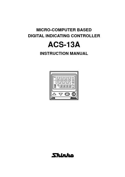
MICRO-COMPUTER BASED DIGITAL INDICATING CONTROLLERACS-13AINSTRUCTION MANUALPrefaceThank you for purchasing of our microcomputer based digital indicating controller ACS-13A. This manual contains instructions for the mounting, functions, operations and notes when operating the ACS-13A. To prevent accidents arising from the misuse of this controller, please ensure the operator receives this manual.Characters used in this manual :Number,/ -1 0 1 2 3 4 5 6 7 8 9IndicationAlphabet A B C D E F G H I J K L MIndicationAlphabet N OP Q RSTUVWXY Z IndicationNotes• This instrument should be used in accordance with the specifications described in the manual.If it is not used according to the specifications, it may malfunction or cause fire.• Be sure to follow the warnings, cautions and notices. If they are not observed, serious injury or malfunction may occur. • The contents of this instruction manual are subject to change without notice.• Care has been taken to assure that the contents of this instruction manual are correct, but if there are any doubts, mistakes or questions, please inform our sales department.• This instrument is designed to be installed within a control panel. If it is not, measures must be taken to ensure that the operator cannot touch power terminals or other high voltage sections. • Any unauthorized transfer or copying of this document, in part or in whole, is prohibited.• Shinko Technos CO., LTD. is not liable for any damage or secondary damage(s) incurred as a result of using this product, including any indirect damage.Safety precautions (Be sure to read these precautions before using our products.)The safety precautions are classified into categories: “Warning” and “Caution”. Depending on circumstances, procedures indicated by Caution may be linked to serious results, so be sure to follow the directions for usage.WarningWarning• To prevent an electric shock or fire, only Shinko or qualified service personnel may handle the inner assembly. • To prevent an electric shock, fire or damage to the instrument, parts replacement may only be undertaken by Shinko or qualified service personnel.• To ensure safe and correct use, thoroughly read and understand this manual before using this instrument.Caution with respect to Export Trade Control OrdinanceT o avoid this instrument from being used as a component in, or as being utilized in the manufacture of weapons of mass destruction (i.e. military applications, military equipment, etc.), please investigate the end users and the final use of this instrument. In the case of resale, ensure that this instrument is not illegally exported.Procedures which may lead to dangerous conditions and cause death or serious injury, if not carried out properly .Procedures which may lead to dangerous conditions and cause superficial to medium injury or physical damage or may degrade or damage the product, if not carried out properly.1. Installation precautionsCautionThis instrument is intended to be used under the following environmental conditions(IEC61010-1): Overvoltage category , Pollution degree 2Ensure the mounting location corresponds to the following conditions:• A minimum of dust, and an absence of corrosive gases• No flammable, explosive gases• No mechanical vibrations or shocks• No exposure to direct sunlight, an ambient temperature of 0 to 50(32 to 122) that does not change rapidly, and without icing• An ambient non-condensing humidity of 35 to 85%RH• No large capacity electromagnetic switches or cables through which large current is flowing.• No water, oil or chemicals or where the vapors of these substances can come into direct contact with the unitNote • Do not install this instrument near flammable material even though the case of this instrument is made of flame-resistant resin.Avoid setting this instrument directly on flammable material.2. Wiring precautionsCaution• Do not leave bits of wire in the instrument, because they could cause fire or malfunction.• Use the solderless terminal with an insulation sleeve in which the M3 screw fits when wiring the ACS-13A.• The terminal block of this instrument is designed to be wired from the left side.The lead wire must be inserted from the left side of the terminal, and fastened with the terminal screw.• Tighten the terminal screw to within the specified torque. If excessive force is applied to thescrew when tightening, the terminal screw or case may be damaged.• When using a terminal cover, pass terminal wires numbered 7 to 12 into the holes of the terminal cover.• This instrument does not have a built-in power switch, circuit breaker or fuse.It is necessary to install them near the controller.(Recommended fuse: Time-lag fuse, rated voltage 250V AC, rated current 2A)• For a 24V AC/DC power source, do not confuse polarity when using direct current (DC).• Do not apply a commercial power source to the sensor which is connected to the input terminal nor allow the power source to come into contact with the sensor.• Use a thermocouple and compensating lead wire according to the sensor input specifications of this controller.• Use the 3-wire RTD according to the sensor input specifications of this controller.• (+) side input terminal number of 0 to 5V DC, 1 to 5V DC, 0 to 10V DC differs from that of 0 to 1V DC.(+) side input terminal number of 0 to 5V DC, 1 to 5V DC, 0 to 10V DC: 9(+) side input terminal number of 0 to 1V DC: 10• When using a relay contact output type, externally use a relay according to the capacity of the load to protect the built-in relay contact.• When wiring, keep input wires (thermocouple, RTD, etc.) away from AC sources or load wires to avoid external interference.3. Operation and maintenance precautionsCaution• It is recommended that PID auto-tuning be performed on the trial run.• Do not touch live terminals. This may cause electric shock or problems in operation.• Turn the power supply to the instrunment OFF when retightening the terminal or cleaning.Working or touching the terminal with the power switched ON may result in severe injury or death due to Electric Shock.• Use a soft, dry cloth when cleaning the instrument.(Alcohol based substances may tarnish or deface the unit.)• As the display section is vulnerable, do not strike or scratch it with a hard object or press hard on it.ContentsPage 1. Model -------------------------------------------------------------------------------------- 51.1 Model ---------------------------------------------------------------------------------- 51.2 How to read the model label ----------------------------------------------------- 52. Name and functions of the sections ------------------------------------------- 63. Mounting to the control pane l ---------------------------------------------------- 73.1 External dimensions (Unit: mm) ------------------------------------------------ 73.2 Panel cutout (Unit: mm) ---------------------------------------------------------- 73.3 CT (Current transformer) external dimensions (Unit: mm) --------------- 73.4 Mounting and removal to/from the control panel ---------------------------- 84. Wiring ------------------------------------------------------------------------------------- 94.1 Terminal arrangement ------------------------------------------------------------- 94.2 Lead wire solderless terminal ---------------------------------------------------- 94.3 Terminal cover ---------------------------------------------------------------------- 104.4 Heater burnout alarm output (W, W3option) wiring ----------------------- 105. Operation flowchart ---------------------------------------------------------------- 116. Setup ------------------------------------------------------------------------------------ 126.1 Turn the power supply to the ACS-13A ON -------------------------------- 126.2 Basic key operations ------------------------------------------------------------- 126.3 Setup mode ------------------------------------------------------------------------ 137. Settings -------------------------------------------------------------------------------- 207.1 Main setting mode ---------------------------------------------------------------- 207.2 Sub setting mode ----------------------------------------------------------------- 217.3 Auxiliary function setting mode ------------------------------------------------ 238. Running ------------------------------------------------------------------------------- 248.1 Starting operation ----------------------------------------------------------------- 248.2 Control output OFF function ---------------------------------------------------- 258.3 Auto/Manual control switching ------------------------------------------------- 258.4 Indicating output MV ------------------------------------------------------------- 268.5 Auto-tuning/Auto-reset Perform/Cancel ------------------------------------- 269. Auto-reset ----------------------------------------------------------------------------- 2610. Auto-tuning ---------------------------------------------------------------------------- 2711. Action explanation ------------------------------------------------------------------ 2811.1 OUT1 action ---------------------------------------------------------------------- 2811.2 OUT1 ON/OFF action ---------------------------------------------------------- 2811.3 Heater burnout alarm action -------------------------------------------------- 2911.4 Alarm action ---------------------------------------------------------------------- 2911.5 OUT2 (Heating/Cooling control) action ----------------------------------- 3011.6 OUT2 (Heating/Cooling control) action (When setting Dead band) ----- 3011.7 OUT2 (Heating/Cooling control) action (When setting Overlap band) -- 3112. Specifications ------------------------------------------------------------------------ 3212.1 Standard specifications -------------------------------------------------------- 3212.2 Optional specifications --------------------------------------------------------- 3513. Troubleshooting --------------------------------------------------------------------- 3713.1 Indication -------------------------------------------------------------------------- 3713.2 Key operation -------------------------------------------------------------------- 3813.3 Control ----------------------------------------------------------------------------- 3814 Character table ----------------------------------------------------------------------- 391. Model 1.1 ModelS Non-contact voltage (for SSR drive): 12V DC15%AInput M1Non-contact voltage: 12V DC15%*1: Alarm types (9 types and No alarm action) and Energized/Deenergized can be selected by keypad.*2: Thermocouple, RTD, DC current and DC voltage can be selected by keypad.For DC current input, connect 50shunt resistor (sold separately) externally.*3: Supply voltage 100 to 240V AC is standard. When ordering 24V AC/DC, enter “1” after the input code.1.2 How to read the model labelThe model label is attached to the left side of the case.For Heater burnout alarm output, CT rated current is written in the bracket.(1): Model, Power supply (For 24V AC/DC, “1” is entered), Options(2): Serial number(e.g.)Relay contact output/Multi-range input(Fig.1.2-1)(2)2. Name and functions of the sections(Fig. 2-1)Display (1) PV indicator : Lights when PV is indicated in the PV/SV display mode. (2) PV display : Indicates the PV (process variable). (3) SV indicator : Lights when SV is indicated in the PV/SV display mode.(4) MEMO indicator : Lights when Set value memory external selection (SM option) is added. (5) MEMO display : Indicates the set value memory number. (6) SV display : Indicates the SV (Main set value). (7) Action indicators O1 (OUT1) : Lights when control output is ON or when Heating output (D option) is ON. For DC current output type, flashescorresponding to the MV in 0.25 second cycles.O2 (OUT2) : Lights when cooling output (D option) is ON. EV1 : Lights when Alarm 1 output is ON. EV2 : Lights when Alarm 2 output (A2 option) is ON or when Heater burnout alarm (W, W3 option) is ON. AT : Flashes while AT (auto-tuning) or auto-reset is performing. T/R : Lights during Serial communication (C5 option) (TX output).LOCK : Lights when Lock 1, Lock 2 or Lock 3 is selected.Key operations (8) Increase key : Increases the numeric value. (9) Decrease key : Decreases the numeric value. (10) Mode key : Selects the setting mode, or registers the set value. To register the set (selected) value, press this key.(11) OUT/OFF key : Switches control output ON/OFF or Auto/Manual control.To release the control output ON/OFF, press this key for approx. 1sec.(12) Console connector :By connecting to the USB communication cable (CMA, sold separately), the following operations can be conducted from the external computer using the Console software SWS-ACS01M. • Reading and setting of SV, PID and various set values• Reading of PV and action status • Function change(10)(11)3. Mounting to the control panel3.1 External dimensions (Unit: mm)(Fig. 3.1-1)3.2 Panel cutout(Unit: mm)CautionIf lateral close mounting is used for the controller, IP66 specification (Dust-proof/Drip-proof) may be compromised, and all warranties will be invalidatedLateral close mountingn: Number of units mounted(Fig. 3.2-1)3.3 CT (Current transformer) external dimensions (Unit: mm)CTL-6S (for 20A) CTL-12-S36-10L1 (for 50A)(Fig. 3.3-1)754545+0.5045+0.50n x 48-3+0.50(*) When a terminal cover (sold separately) is used.3.4 Mounting and removal to/from the control panelCautionAs the mounting frame is made of resin, do not use excessive force while tightening screws, or the mounting frame could be damaged.Tighten screws with one rotation upon the screw tips touching the panel. The torque is approximately 0.05 to 0.06 N•m.How to mount the ACS-13AMount the controller vertically to the flat, rigid panel to ensure it adheres to the Dust-proof/Drip-proof specification (IP66).Mountable panel thickness: Within 1 to 5mm(1) Insert the controller from the front side of the panel. (Fig.3.4-1)(2) Insert the unit until mounting frame comes into contact with the panel, and fasten with the screw. Tighten screws with one rotation upon the screw tips touching the panel. (Fig.3.4-2) The torque is approximately 0.05 to 0.06N•m.(Fig.3.4-1)How to remove the mounting frame and unit (Fig. 3.4-3)(1) Turn the power to the unit OFF, and disconnect all wires before removing the mounting frame. (2) Insert a flat blade screwdriver between the screw frame and unit (3) Slowly push the frame upward using the screwdriver (4) Repeat step (2) and slowly push the frame downward using the screwdriver for the other side.The frame can be removed little by little by repeating these steps.(Fig.3.4-3)(Fig.3.4-2)Mounting frame4. WiringWarningTurn the power supply to the instrument off before wiring or checking.Working or touching the terminal with the power switched on may result in severe injury or death due to Electric Shock.4.1 Terminal arrangement(Fig. 4-1) • POWERSUPPLY: For a 24V AC/DC power source, do not confuse polarity when using direct current (DC). • EV1 : Alarm 1 output • O2/EV2: Cooling output (D option), Alarm 2 output (A2 option) or Heater burnout alarm output (W, W3 option) • O1 : Control output or Heating output (D option) • DC : DC current, DC voltage input(For DC voltage input, + side terminal number differs depending on the voltage input.) (+) side input terminal number of 0 to 5V DC, 1 to 5V DC, 0 to 10V DC: 9(+) side input terminal number of 0 to 1V DC: 10• TC : Thermocouple input• RTD : Resistance temperature detector input • CT1 : CT input 1 (W, W3 option) • CT2 : CT input 2 (W3 option) • DI : Contact input (SM option) • RS-485 : Serial communication RS-485 (C5 option)4.2 Lead wire solderless terminalUse a solderless terminal with an insulation sleeve in which an M3 screw fits as shown below. The torque is approximately 0.6N•m to 1.0N•m. Solderless terminal Manufacturer ModelTighteningtorqueNichifu T erminal Industries CO.,LTD. 1.25Y -3Y typeJapan Solderless T erminal MFG CO.,LTD.VD1.25-B3A Nichifu T erminal Industries CO.,LTD.1.25-3 Round type Japan Solderless T erminal MFG CO.,LTD. V1.25-30.6N•mMax. 1.0N•m(Fig. 4.2-1)POWER SUPPLY+ 3A 250V AC 3A250V AC + DI2DI1COM YA(-)YB(+)SG DI RS-4853A 250VAC + +++DC 0 to 1V 4 to 20mA 0 to 20mADC4.3 Terminal coverWhen using a terminal cover (sold separately), pass terminal wires numbered 7 to 12 into the holes of the terminal cover.(Fig. 4.3-1)4.4 Wiring Heater burnout alarm output (W, W3 option)This alarm is not usable for detecting heater current under phase control.Use the CT (current transformer) provided, and pass one lead wire of the heater circuit into the hole of the CT. (Fig. 4.4-1).When wiring, keep the CT wire away from AC sources or load wires to avoid the external interference.(Fig. 4.4-1)In the case of 3-phase (W3 option), pass any 2 lead wires of R, S, T into the CT, and connect them with CT1 (13, 14) and CT2 terminals (14, 15). (Fig.4.4-2)Pass any 2 wires of R, S and T into CT.(Fig. 4.4-2)RS T5. Operation flowchartPower ONControl output OFF/Manual control Control output OFF (Approx. 1sec) Auto/Manual control PV/SV display mode (Automatic control)For 3 seconds after the power is turned on, the PV display indicates the input type, and the SV display indicates input range high limit value (TC, RTD) or scaling high limit value (DC voltage, DC current). (Approx. 3sec) Output MV indication[Main setting mode] SV+ [Sub setting mode] Auto-tuning/ Auto-reset+ (Approx. 3sec) [Auxiliary function setting mode] Set value lock+ (Approx. 3sec) [Setup mode] Input typeAlarm 1 hysteresisSV2OUT1 proportional band OUT2 proportional band Integral timeSensor correctionScaling high limitAlarm 2 hysteresisSV3Communication protocolScaling low limitAlarm 1 action delayed timerSV4Instrument numberDecimal point placeAlarm 2 action delayed timerDerivative timeCommunication speedPV filter time constantSV rise rateARWData bit/ParityOUT1 high limitSV fall rateOUT1 proportional cycle OUT2 proportional cycle Alarm 1 valueStop bitOUT1 low limitDirect/Reverse control actionOUT1 ON/OFF action hysteresisAT biasOUT2 action modeSVTC biasAlarm 2 valueOUT2 high limitContact input functionHeater burnout alarm value (*1) Heater burnout alarm 2 value (*2)OUT2 low limitOutput status selection when input abnormal OUT/OFF key functionOverlap band/ Dead bandOUT2 ON/OFF action hysteresisBacklightAlarm 1 typePV color[Key operation]• • • • + + : Press the key while pressing the key. (Approx.3sec): Press the key for approx. 3 seconds while holding down the key. + (Approx.3sec): Press the key for approx. 3 seconds while holding down the key. : This means that if the (MODE) key is pressed, the unit proceeds to the next setting mode.Alarm 2 type PV color rangeAlarm 1 Energized/ Deenergized Alarm 2 Energized/ DeenergizedBacklight time[Setting item]• PV display indicates setting item characters, and SV display indicates default value. (*1) CT1 current value and character are indicated alternately. (*2) CT2 current value and characters are indicated alternately. • Setting items with dotted lines (shaded) are optional, and they appear only when the options are added.Indication selection when output OFF OUT1 rate of change limit116. SetupSetup should occur before using this controller, to set the Input type, Alarm type, Control action, etc. according to the users’ conditions. Default values: Input (K, -200 to1370 ), Alarm 1 (No alarm action), Reverse (Heating) action If the users’ specification is the same as the default value of the ACS-13A, it is not necessary to set up the controller. Proceed to Chapter “7. Settings”. 6.1 Turn the power supply to the ACS-13A ON. After the power is turned on, the PV display indicates the input type, and the SV display indicates the input range high limit value (thermocouple, RTD input) or scaling high limit value (DC input) for approximately 3 seconds. (Table 6.1-1) During this time, all outputs and the indicators are in OFF status. Control will then start indicating the PV (process variable) on the PV display and SV (main set value) on the SV display. . While control output OFF function is working, the PV display indicates (Indication depends on the selection during “Output status selection when input abnormal”.) (Table 6.1-1) Sensor input K J R S B E T N PLC (W/Re5-26) Pt100 JPt100 4 to 20mA DC 0 to 20mA DC 0 to 1V DC 0 to 5V DC 1 to 5V DC 0 to 10V DC PV display SV display PV display SV displayScaling high limit value6.2 Basic key operations To enter each setting mode, refer to respective setting modes. or key, then register the value with the To set or select each setting item, use thekey.126.3 Setup mode To enter the Setup mode, press the PV/SV display mode. Characterkey for approx. 3 seconds while holding down thekey in theName, Function, Setting range Default value Input type selection K (-200 to 1370 ) • The input type can be selected from thermocouple (10 types), RTD (2 types), DC current (2 types) and DC voltage (4 types), and the unit / can be selected as well. • When changing the input from DC voltage to other inputs, remove the sensor connected to this controller first, then change for the input. If the input is changed with the sensor connected, the input circuit may break. • (+) side input terminal number of 0 to 5V DC, 1 to 5V DC, 0 to 10V DC differs from that of 0 to 1V DC. (+) side input terminal number of 0 to 5V DC, 1 to 5V DC, 0 to 10V DC: 9 (+) side input terminal number of 0 to 1V DC: 10 K -320 to 2500 K -200 to 1370K J R S B E T N PLC(W/Re5-26) Pt100 JPt100 Pt100 JPt100 4 to 20mA DC0 to 20mA DC-200.0 -200 0 0 0 -200 -200.0 -200 0 0 -200.0 -200.0 -200 -200 -2000to 400.0 to 1000 to 1760 to 1760 to 1820 to 800 to 400.0 to 1300 to 1390 to 2315 to 850.0 to 500.0 to 850 to 500 to 10000K -320.0 to 750.0 J -320 to 1800 R 0 to 3200 S 0 to 3200 B 0 to 3300 E -320 to 1500 T -320.0 to 750.0 N -320 to 2300 PL0 to 2500 C(W/Re5-26) 0 to 4200 Pt100 -320.0 to 1500.0 JPt100 Pt100 JPt100 -320.0 to 900.0 -320 to 1500 -320 to 900-2000 to 10000 0 to 1V DC -2000 to 10000 0 to 5V DC -2000 to 10000 1 to 5V DC -2000 to 10000 0 to 10V DC -2000 to 10000 Scaling high limit setting 1370 • Sets scaling high limit value. • Setting range: Scaling low limit value to input range high limit value DC voltage, current input: -2000 to 10000 (The placement of the decimal point follows the selection.) Scaling low limit setting -200 • Sets scaling low limit value. • Setting range: Input range low limit value to scaling high limit value DC voltage, current input: -2000 to 10000 (The placement of the decimal point follows the selection.) Decimal point place selection No decimal point • Selects decimal point place. Available only for DC input : No decimal point • : 1 digit after decimal point : 2 digits after decimal point : 3 digits after decimal point 13PV filter time constant setting 0.0 seconds • Sets PV filter time constant. If the value is set too large, it affects control result due to the delay of response. • Setting range: 0.0 to 10.0 seconds OUT1 high limit setting 100% • Sets the high limit value of OUT1. Not available if OUT1 is ON/OFF action • Setting range: OUT1 low limit value to 100% (DC current output type: OUT1 low limit value to 105%) OUT1 low limit setting 0% • Sets the low limit value of OUT1. Not available if OUT1 is ON/OFF action. • Setting range: 0% to OUT1 high limit value (DC current output type: -5% to OUT1 high limit value) OUT1 ON/OFF action hysteresis setting 1.0 • Sets ON/OFF action hysteresis for OUT1. Available only when OUT1 is ON/OFF action • Setting range: 0.1 to 100.0 ( ), DC voltage, current input: 1 to 1000 (The placement of the decimal point follows the selection.) OUT2 action mode selection Air cooling • Selects OUT2 action from air, oil and water cooling. Not available if the D option is not added or if OUT2 is ON/OFF action Air cooling (linear characteristic) • Oil cooling (1.5th power of the linear characteristic) Water cooling (2nd power of the linear characteristic)OUT2 proportional band Air cooling Oil cooling Water cooling SV setting(Fig. 6.3-1) OUT2 high limit setting 100% • Sets OUT2 high limit value. Not available if the D option is not added or if OUT2 is ON/OFF action • Setting range: OUT2 low limit value to 100% OUT2 low limit setting 0% • Sets OUT2 low limit value. Not available if the D option is not added or if OUT2 is ON/OFF action • Setting range: 0% to OUT2 high limit value Overlap band/Dead band setting 0.0 • Sets the overlap band or dead band for OUT1 and OUT2. + Set value: Dead band, –Set value: Overlap band Available only when the D option is added • Setting range: -100.0 to 100.0 ( ), DC voltage, current input: -1000 to 1000 (The placement of the decimal point follows the selection.) OUT2 ON/OFF action hysteresis setting 1.0 • Sets ON/OFF action hysteresis for OUT2. Available when the D option is added, and when OUT2 is ON/OFF control action. • Setting range: 0.1 to 100.0 ( ), DC voltage, current input: 1 to 1000 (The placement of the decimal point follows the selection.)14Alarm 1 type selection No alarm action • Selects an Alarm 1 type. (Refer to “11.4 Alarm action” on p.29.) : No alarm action : High limit alarm : Low limit alarm : High/Low limits alarm : High/Low limit range alarm : Process high alarm : Process low alarm : High limit alarm with standby : Low limit alarm with standby : High/Low limits alarm with standby Alarm 2 (A2) type selection No alarm action • Selects an Alarm 2 type. (Refer to “11.4 Alarm action” on p.29.) Available only when Alarm 2 (A2) option is added • Selection items are the same as those of Alarm 1. Alarm 1 Energized/Deenergized selection Energized • Selects Energized/Deenergized status for Alarm 1. (See p.18.) Not available if No alarm action is selected during Alarm 1 type selection : Energized • : Deenergized Alarm 2 Energized/Deenergized selection Energized • Selects Energized/Deenergized status for Alarm 2. (See p.18.) Not available if Alarm 2 (A2) option is not added or if No alarm action is selected during Alarm 2 type selection • Selection items are the same as those of Alarm 1 Energized/Deenergized selection. Alarm 1 hysteresis setting 1.0 • Sets hysteresis for Alarm 1. Not available if No alarm action is selected during Alarm 1 type selection • Setting range: 0.1 to 100.0 ( ), DC voltage, current input: 1 to 1000 (The placement of the decimal point follows the selection.) Alarm 2 hysteresis setting 1.0 • Sets hysteresis for Alarm 2. Not available if Alarm 2 (A2) option is not added or if No alarm action is selected during Alarm 2 type selection • Setting range: 0.1 to 100.0 ( ), DC voltage, current input: 1 to 1000 (The placement of the decimal point follows the selection.) Alarm 1 action delayed timer setting 0 seconds • Sets action delayed timer for Alarm 1. When setting time has elapsed after the input enters the alarm output range, the alarm is activated. Not available if No alarm action is selected during Alarm 1 type selection • Setting range: 0 to 10000 seconds Alarm 2 action delayed timer setting 0 seconds • Sets action delayed timer for Alarm 2. When setting time has elapsed after the input enters the alarm output range, the alarm is activated. Not available if Alarm 2 (A2) option is not added or if No alarm action is selected during Alarm 2 type selection • Setting range: 0 to 10000 seconds 15。
PC-935温控表(0#烧结炉)一、仪表显示面板键二、程序跳步由程序控制方式运行时,按键或“跳步”按钮,可跳到下一步程序。
三、自动/手动功能设置按,再按几次直到出现,再按键进入自动/手动输出方式选择:可选择输出由仪表控制(自动)还是手动方式。
四、程序控制方式1、程序设置1.1接通温度调节器电源,按进入设置模式,显示模式设置方式。
1.2按进入模式号设置方式,按△或▽键选择将要编程的程序组(组号在PTN框显示)。
1.3按进入步SV(设定)值,再按几次可分别设定各步的SV值(步号显示在STEP窗口,0-9共10步),按△或▽键设置具体参数。
1.4按进入步时间,再按几次可分别设定各步的时间值(步号显示在STEP窗口0-9共10步),按△或▽键设置具体参数。
1.5按进入PID模块号,TS1-TS8时标模块号,,等待模块号,默认值为0,可不修改。
1.6按返回显示画面。
2、设置各模块参数值(仅作了解)按,再按进入模块设置方式,可设置PID模块,时标模块,等待模块,报警模块,输出模块的参数。
2.1按进入PID模块:按依次可设置0-9号共10个PID模块的主比例带,积分时间,微分时间,抗积分饱和,副比例带(有副输出时有效)2.2 再按进入时标功能:按依次可设置提供在程序步控制期间,8个时间信号的输出。
共有8组(开/关为一组)模块数据可设置。
2.3再按进入等待模块数据的设定:按,在此设置0-9共10个等待值,在程序控制期间,当步程序结束时,测量值仍未达到【设定值-等待值】或【设定值+等待值】,那么将不进入下一步程序,而进入等待状态STEP窗口闪烁,直到按进入下一步程序,或按键停止程序。
2.4 再按进入报警模块设置:按,设置A1-A4报警点各步的报警数值,按△或▽键设置具体参数。
2.4 再按进入输出功能模块设置:按,在此可设置10个数据模块中的参数(主输出上/下限,副输出上/下限,主输出的改变速率)。
新一代燃气锅炉电脑控制器使用说明书北京亿明电气设备有限公司目录及注意事项一、概述二、安装接线三、显示四、基本操作五、参数设定六、运行与控制七、报警和连锁保护八、异常处理及故障排除附表、附图感谢您使用本公司产品,为了正确使用本机并充分发挥效用,请您在使用之前务必仔细阅读说明书!开箱检查:◇观察产品包装箱上标示的规格、型号,确认和您定购的相符◇按装箱单核对产品、附件的规格、数量◇确认本机在运输过程中没有损坏◇有任何问题请在3日内与本公司联络。
如在收到货物7日内未与本公司书面联络,则视同您已认可。
超过此限,恕不受理。
安全注意◇本机必须由具有相应资格的专业技术人员按说明书安装◇安装使用的配件必须符合国家电气标准◇确认电源电压在规定的范围之内。
保证良好的接地◇不能将强电接入弱电信号输入端售后服务◇在您遇到问题或设备故障时,请及时与我公司用户服务部门联系。
请您在反映问题时尽量说明:产品的型号、编号、配件、锅炉生产厂、购买日期、使用情况、具体故障现象◇在正常安装、使用的情况下,本机自出厂之日起12个月内发生质量问题实行在厂免费保修。
超过保修期后视情况需收取相应费用◇如出现以下问题,应由用户承担相关费用:①使用不当造成的人为损坏②自然灾害及污染等造成的损坏③电源电压异常、电路连接不当等造成的损坏使用条件◇环境温度:0 ~45 ℃◇大气压力:86 ~106 Kpa◇相对湿度:< 90 %(无结露)◇额定电源电压:220V AC,频率:50Hz◇电源电压范围:额定值的90% ~110%◇强电线路和连接传感器等的弱电线路必须分别穿管走线,否则控制器可能无法正常工作◇温度传感器原配接线需延长时,应使用屏蔽线一、概述新一代燃气系列锅炉电脑控制器是我公司吸收国外先进技术,结合国内锅炉控制的实际需要和具体应用,采用现代电脑控制技术,而推出的新一代燃油燃气锅炉电脑控制器。
适用于燃油燃气蒸汽锅炉、承压热水锅炉、常压热水锅炉和导热油锅炉的自动控制,具有可靠性高、自动化程度高、使用方便、操作简单、功能丰富、控制灵活、造型美观、品种齐全、性能价格比高等优点。
COMMUNICATION INSTRUCTION MANUALJCS, JCM, JCR, JCD-33A, C5No.JC3CE6 2005.04 To prevent accidents arising from the misuse of this controller, please ensure the operator receives this manual.WarningTurn the power supply to the instrument off before wiring or checking it.Working or touching the terminal with the power switched on may result in severe injury or death due to Electric Shock.1. System configurationRS-485 multi-drop connection communication (C5 option)(Fig. 1-1)(Fig. 1-2)Please use the IF-400 (sold separately) as a communication converter. 2. WiringWhen using communication converter IF-400 • 9-pin Dsub connector: Connection: (Communication speed: 2400, 4800, 9600, 19200bps)Host computerConnection: (Communication speed: 2400, 4800, 9600, 19200bps)Shield wireConnect only one side of the shield wire to the FG terminal so that current cannot flow to the shield wire.(If both sides of the shield wire are connected to the FG terminal, the circuit will be closed between the shield wire and the ground. As a result, current will run through the shield wire and this may cause noise.)Be sure to ground the FG terminal. Terminator (Terminal resistor)Do not connect terminator with the communication line because each JC -33A has built-in pull-up and pull-down resistors instead of a terminator.-33A• It is necessary to set the instrument number individually to the JC -33A when communicating byconnecting plural units in serial communication (C5 option).Select a communication speed of the JC -33A in accordance with that of the host computer. • For the instrument number setting and communication speed, refer to the instruction manual for JC -33A.4. Communication procedureCommunication starts with command transmission from the host computer (hereafter Master) and ends with the response of the JC -33A (hereafter Slave).• Response with datathe master sends the reading command, the slaveresponds with the corresponding set value or current • Acknowledgementthe master sends the setting command, the slaveresponds by sending the acknowledgement after theprocessing is terminated. • Negative acknowledgement the master sends non-existent command or value out of the setting range, the slave returns the negative • No responseaddress is set, or when there is a communication error(framing error or checksum error), or when LRC or CRCdiscrepancy is detected.Host computerCommunication timing of the RS-485 (C5 option)Slave sideWhen the slave starts transmission through RS-485 communication line, the slave is arranged so as to provide an idle status (mark status) transmission period of 1 or more characters before sending the response to ensure the synchronization on the receiving side.The slave is arranged so as to disconnect the transmitter from the communication line within a1 character transmission period after sending the response.Master side (Notice on programming)Set the program so that the master can disconnect the transmitter from the communication line withina 1 character transmission period after sending the command in preparation for reception of theresponse from the slave.To avoid the collision of transmissions between the master and the slave, send the next command after carefully checking that the master received the response.5. Shinko protocol5.1 Transmission modeShinko protocol is composed of ASCII codes.Hexadecimal (0 to 9, A to F), which is divided into high order (4-bit) and low order (4-bit) out of 8-bit binary data in command is transmitted as ASCII characters.Data format Start bit : 1 bitData bit : 7 bitsP arity : EvenS top bit : 1 bitError detection: Checksum5.2 Command configurationAll commands are composed of ASCII. The data (set value, decimal number) is represented withhexadecimal number, and ASCII code is used.The negative numbers are represented with 2's complement.(1) Setting command(2) Reading command(3) Response with data(5) Negative acknowledgementHeader: Control code to represent the beginning of the command or the response.ASCII codes are used.Setting command, Reading command : 02H fixedResponse with data, Acknowledgement : 06H fixedNegative acknowledgement : 15H fixed Number of charactersNumber ofcharactersNumber ofcharacters Number ofcharactersNumber ofcharactersAddress (Instrument number): Numbers by which the master discerns each slave. Instrument number 0 to 94 (00H to 5EH) and Global address 95 (7FH) The numbers (20H to 7EH) are used by giving 20H of bias, because 00H to 1FH are used for control code. 95 (7FH) is called Global address , which is used when the same command is sent to all the slaves connected. However, the response is not returned.Sub address : 20H fixedCommand type : Code to discern Setting command (50H) and Reading command (20H) Data item : Data classification of the command object Composed of hexadecimal 4 digits (Refer to the Communication command table) Data : The contents of data (set value) depend on the setting command Composed of hexadecimal 4 digits (Refer to the Communication command table) Checksum : 2-character data to detect communication errors Delimiter : Control code to represent the end of command 03H fixed Error code : Represents an error type. Composed of hexadecimal 1 digit. 1 (31H)-----Non-existent command 2 (32H)-----Not used 3 (33H)-----Setting outside the setting range 4 (34H)-----Status unable to set (e.g. AT is performing) 5 (35H)-----During setting mode by keypad operation5.3 Checksum calculationChecksum is used to detect receiving errors in the command or data.Set the program for the master side as well to calculate the checksum of the response data from the slaves so that the communication errors can be checked. The ASCII code (hexadecimal) corresponding to the characters which range from the address to that before the checksum is converted to binary notation, and the total value is calculated.The lower 2-digit of the total value are converted to 2’s complements, and then to hexadecimal figures, that is, ASCII code for the checksum. Refer to the following example procedure. Checksum calculation example Main set value: 600 (0258H)Address (instrument number): 0 (20H)• 1’s complement: Reverse each binary bit. 0 will become 1 and vice versa. • 2’s complement: Add 1 to 1’s complements.20H50H0010 00000101 00001101 11111+[1's complement][2's complement][Hexadecimal][ASCII]5.4 Contents of the commandNotes on the setting command and reading command• Possible to set the set value by setting command of the communication function even when the set value is locked.• Although the options are not applied, setting the items for the options is possible by the setting command. However, they will not function.• The memory can store up to 1,000,000 (one million) entries.If the number of settings exceeds the limit, the data will not be saved. So frequent transmission via communication is not recommended.• When connecting plural slaves, the address (instrument number) must not be duplicated.• When sending a command by Global address [95 (7FH)], the same command is sent to all the slaves connected. However, the response is not returned.• The instrument number and communication speed of the slave cannot be set by communication function.Setting command• The settable range is the same as that by key operation.For the communication command, refer to the communication command table of this manual. • All commands are composed of ASCII.• The data (set value, decimal) is converted to hexadecimal figures, and ASCII is used.A negative number is represented by 2's complement. When the data (set value) has a decimal point, a whole number without a decimal point is used. Reading command• All commands are composed of ASCII.• The data (set value, decimal) is converted to hexadecimal figures, and ASCII is used.A negative number is represented by 2's complement. When the data (set value) has a decimal point, the response is returned as a whole number without a decimal point.6. Modbus protocol6.1 Transmission modeThere are 2 transmission modes (ASCII and RTU) in Modbus protocol. 6.2 ASCII modeHexadecimal (0 to 9, A to F), which is divided into high order (4-bit) and low order (4-bit) out of 8-bit binary data in command is transmitted as ASCII characters. Data format Start bit : 1 bit Data bit : 7 bits P arity : Even/Odd/No parity (Selectable) S top bit : 1 bit/2 bits (Selectable) Error detection : LRC (Longitudinal Redundancy Check) Data interval : 1 second or less (1) Message configurationASCII mode message is configured to start by [: (colon)(3AH)] and end by [CR (carriage return) (0DH) + LF (Line feed)(0AH)]. (See Fig. 6.2-1)(2) Slave addressSlave address is an individual instrument number on the slave side and is set within the range 00H to 5FH (0 to 95).The master identifies slaves by the slave address of the requested message.The slave informs the master which slave is responding to the master by placing its own address in the response message.[Slave address 00H (broadcast address) can identify all the slaves. However slaves do not respond.] (3) Function codeThe function code is the command code for the slave to undertake the following action types (T able 6.2-1). (Table 6.2-1) Function code Contents 03 (03H) Reading the set value and information from slaves 06 (06H) Setting to slavesFunction code is used to discern whether the response is normal (acknowledgement) or if any error (negative acknowledgement) is occurred when the slave returns the response message to the master. When acknowledgement is returned, the slave simply returns the original function code.When negative acknowledgement is returned, the MSB of the original function code is set as 1 for the response.Slave address FunctioncodeDataError check LRC Delimiter (CR)Header (:)Delimiter (LF)(For example, when the master sends request message setting 10H to function code by mistake, slave returns 90H by setting the MSB to 1, because the former is an illegal function.)For negative acknowledgement, exception code (Table 6.2-2) below is set to the data of response message and returned to the master in order to inform it that what kind of error has occurred. (Table 6.2-2)Exception code Contents1 (01H) Illegal function (Non-existent function)2 (02H) Illegal data address (Non-existent data address)3 (03H)Illegal data value (Value out of the setting range)17 (11H)Illegal setting (Unsettable status)18 (12H) Illegal setting (During setting mode by key operation, etc)(4) DataData depends on the function code.A request message from the master is composed of data item, number of data and setting data.A response message from the slave is composed of number of bytes, data and exception codein negative acknowledgement. Effective range of data is –32768 to 32767 (8000H to 7FFFH).(5) Error check of ASCII modeAfter calculating LRC (Longitudinal Redundancy Check) from the slave address to the end of data, the calculated 8-bit data is converted to two ASCII characters and are appended to the end of message.Create a message in RTU mode.Add all the values from the slave address to the end of data. This is assumed as X.Make a complement for X (bit reverse). This is assumed as X.Add a value of 1 to X. This is assumed as X.Set X as an LRC to the end of the message.Convert the whole message to ASCII characters.Reading (Instrument number 1, SV)• A request message from the masterThe number of data means the data item to be read, and it is fixed as (30H 30H 30H 31H).• A response message from the slave in normal status (When SV=100)(Fig.6.2-3) The number of response bytes means the number of bytes of the data which has been read,and it is fixed as (30H 32H).• A response message from the slave in exception (error) status (When data item is mistaken)The function code MSB is set to 1 for the response message in exception (error) status (83H).The exception code (02H: Non-existent data address) is returned as contents of error.Setting (Instrument number 1, SV=100)• A request message from the master(Fig.6.2-5)• A response message from the slave in normal status(Fig.6.2-6)SlaveaddressFunctioncodeData itemError checkLRCDelimiterHeader(30H 31H)Number ofdata(3AH)1224422(30H 33H)(30H 30H 30H 31H)(30H 30H 30H 31H)(46H 41H)(0DH 0AH)Number ofcharactersSlaveaddressFunctioncodeNumber ofresponse bytesError checkLRCDelimiterHeader Data1222422(3AH)(30H 31H)(30H 33H)(30H 32H)(30H 30H 36H 34H)(39H 36H)(0DH 0AH)Number ofcharacters(0DH 0AH)SlaveaddressFunctioncodeExceptioncodeError checkLRCDelimiterHeader122222Number ofcharacters(3AH)(30H 31H)(38H 33H)(30H 32H)(37H 41H)SlaveaddressFunctioncodeData itemError checkLRCDelimiterHeader(30H 31H)Data(3AH)1224422Number ofcharacters(30H 36H)(30H 30H 30H 31H)(30H 30H 36H 34H)(39H 34H)(0DH 0AH)SlaveaddressFunctioncodeData itemError checkLRCDelimiter Header Data1224422Number ofcharacters (3AH)(30H 31H)(30H 36H)(30H 30H 30H 31H)(30H 30H 36H 34H)(39H 34H)(0DH 0AH)• A response message from the slave in exception(error) status (When a value out of the setting range is set)(Fig. 6.2-7)The function code MSB is set to 1 for the response message in exception (error) status (86H). The exception code (03H: Value out of the setting range) is returned as contents of error.6.3 RTU mode8-bit binary data in command is transmitted as it is. Data format Start bit : 1 bit Data bit : 8 bits Parity : Even/Odd/No parity (Selectable) Stop bit : 1 bit/2 bits (Selectable) Error detection : CRC-16 (Cyclic Redundancy Check) Data interval : 3.5 characters transmission time or less (1) Message configurationRTU mode is configured to start after idle time is processed for more than 3.5 character transmission and end after idle time is processed for more than 3.5 character transmission. (See Fig. 6.3-1) (Fig. 6.3-1) (2) Slave addressSlave address is an individual instrument number on the slave side and is set within the range 00H to 5FH (0 to 95).The master identifies slaves by the slave address of the requested message.The slave informs the master which slave is responding to the master by placing its own address in the response message.[Slave address 00H (broadcast address) can identify all the slaves. However slaves do not respond.] (3) Function codeThe function code is the command code for the slave to undertake the following action types (T able 6.3-1). (Table 6.3-1) Function code Contents 03 (03H) Reading the set value and information from slaves 06 (06H) Setting to slavesFunction code is used to discern whether the response is normal (acknowledgement) or if any error (negative acknowledgement) is occurred when the slave returns the response message to the master. When acknowledgement is returned, the slave simply returns the original function code.When negative acknowledgement is returned, the MSB of the original function code is set as 1 for the response.(For example, when the master sends request message setting 10H to function code by mistake, slave returns 90H by setting the MSB to 1, because the former is an illegal function.)For negative acknowledgement, exception code (Table 6.3-2) below is set to the data of response message and returned to the master in order to inform it that what kind of error has occurred. (Table 6.3-2)Exception code Contents 1 (01H) Illegal function (Non-existent function) 2 (02H) Illegal data address (Non-existent data address) 3 (03H) Illegal data value (Value out of the setting range) 17 (11H) Illegal setting (Unsettable status) 18 (12H) Illegal setting (During setting mode by keypad operation, etc) (4) DataData depends on the function code.A request message from the master side is composed of data item, number of data and setting data. A response message from the slave side is composed of number of bytes, data and exception code in negative acknowledgement. Effective range of data is –32768 to 32767 (8000H to 7FFFH). (5) Error check of RTU modeAfter calculating CRC-16 (Cyclic Redundancy Check) from the slave address to the end of data, the calculated 16-bit data is appended to the end of message in sequence from low order to high order.3.5 idle characters Slave address Function codeData Error check CRC 3.5 idlecharacters Slave addressFunction codeException codeError checkLRCDelimiterHeader2Number ofcharacters 22221(3AH)(30H 31H)(38H 36H)(30H 33H)(37H 36H)(0DH 0AH)How to calculate CRCIn the CRC system, the information is divided by the polynomial series. The remainder is added to the end of the information and transmitted. The generation of polynomial series is as follows.16 + X 15+ X 2 + 1)Initialize the CRC-16 data (assumed as X) (FFFFH).Calculate exclusive OR (XOR) with the 1st data and X. This is assumed as X.Shift X one bit to the right. This is assumed as X.When a carry is generated as a result of the shift, XOR is calculated by X ofand the fixeduntil shifting 8 times.up to the last data.Set X as CRC-16 to the end of message in sequence from low order to high order. RTU modeReading (Instrument number 1, SV) • Request message from the masterThe number of data means the data item to be read, and it is fixed as 0001H. • Response message from the slave in normal status (When SV=100)(Fig. 6.3-3)The number of response byte means number of bytes of the data which has been read, and it is fixed as 02H.• Response message from the slave in exception (error) status (When non-existent data item is sent)The function code MSB is set to 1 for the response message in exception (error) status (83H). The exception code (02H: Non-existent data address) is returned as contents of error. Setting (Instrument number 1, SV=100) • Request message from the master• Response message from the slave in normal status• Response message from the slave in exception (error) status (When a value out of the setting range is set)The function code MSB is set to 1 for the response message in exception (error) status (86H). The exception code (03H: Value out of the setting range) is returned as contents of error.3.5 idle charactersSlave address Function code Data itemError check CRC 3.5 idle characters(01H)(03H)(0001H)Number of data (0001H)(D5CAH)11222Number of characters3.5 idle charactersSlave address Function code Number of response bytesError check CRC 3.5 idle characters(01H)(03H)(02H)Data(0064H)(B9AFH)11122characters3.5 idle charactersSlave address Function code Exception code Error check CRC 3.5 idle characters(01H)(83H)(02H)(C0F1H)1112Number of characters3.5 idle charactersSlave address Function code Data item Error check CRC 3.5 idle characters(01H)(06H)(0001H)Data (0064H)(D9E1H)11222characters 3.5 idle charactersSlave address Function code Data item Error check CRC 3.5 idle characters(01H)(06H)(0001H)Data(0064H)(D9E1H)112223.5 idle characters Slave address Function code Exception code Error check CRC 3.5 idle characters(01H)(86H)(03H)(0261H)1112characters7. Communication command tableWhen the data (set value) has a decimal point, remove the decimal point and represent it as a whole number, then express it in hexadecimal figures.Shinko command type ModbusfunctioncodeData item Data20H/50H 03H/06H 0001H: SV1 Set value20H/50H 03H/06H 0002H: Not used20H/50H 03H/06H 0003H: AT/Auto-reset setting 0000H: Cancel 0001H: Perform 20H/50H 03H/06H 0004H: OUT1 proportional band setting Set value20H/50H 03H/06H 0005H: OUT2 proportional band setting Set value20H/50H 03H/06H 0006H: Integral time setting Set value20H/50H 03H/06H 0007H: Derivative time setting Set value20H/50H 03H/06H 0008H: OUT1 proportional cycle setting Set value20H/50H 03H/06H 0009H: OUT2 proportional cycle setting Set value20H/50H 03H/06H 000AH: Not used20H/50H 03H/06H 000BH: A1 setting Set value20H/50H 03H/06H 000CH: A2 setting Set value20H/50H 03H/06H 000DH: Not used20H/50H 03H/06H 000EH: Not used20H/50H 03H/06H 000FH: HB (Heater burnout alarm)settingSet value20H/50H 03H/06H 0010H: LA (Loop break alarm) timesettingSet value20H/50H 03H/06H 0011H: LA (Loop break alarm) spansettingSet value20H/50H 03H/06H 0012H: Set value lock selection (*1) 0000H: Unlock 0001H: Lock 10002H: Lock 2 0003H: Lock 3 20H/50H 03H/06H 0013H: SV high limit setting Set value20H/50H 03H/06H 0014H: SV low limit setting Set value20H/50H 03H/06H 0015H: Sensor correction value setting Set value20H/50H 03H/06H 0016H: Overlap/Dead band setting Set value20H/50H 03H/06H 0017H: Not used20H/50H 03H/06H 0018H: Scaling high limit setting Set value20H/50H 03H/06H 0019H: Scaling low limit setting Set value20H/50H 03H/06H 001AH: Decimal point place selection 0000H: XXXX (No decimal point)0001H: XXX.X (1 digit after decimalpoint)0002H: XX.XX (2 digits after decimalpoint)0003H: X.XXX (3 digits after decimalpoint)20H/50H 03H/06H 001BH: PV filter time constant setting Set value20H/50H 03H/06H 001CH: OUT1 high limit setting Set value20H/50H 03H/06H 001DH: OUT1 low limit setting Set value20H/50H 03H/06H 001EH: OUT1 ON/OFF actionhysteresis settingSet value20H/50H 03H/06H 001FH: OUT2 action mode selection 0000H: Air cooling0001H: Oil cooling0002H: Water cooling20H/50H 03H/06H 0020H: OUT2 high limit setting Set value20H/50H 03H/06H 0021H: OUT2 low limit setting Set value20H/50H 03H/06H 0022H: OUT2 ON/OFF action hysteresissettingSet value20H/50H 03H/06H 0023H: A1 action selection (*2)0024H: A2 action selection (*2) 0000H: No alarm action0001H: High limit alarm0002H: Low limit alarm0003H: High/Low limits alarm 0004H: High/Low limit range alarm 0005H: Process high alarm0006H: Process low alarm0007H: High limit alarm with standby 0008H: Low limit alarm with standby 0009H: H/L limits alarm w/standby[–200 to 1370400.0[–200 to 1000176017601820800400.013001390[0 to 2315[–199.9 to 850.0[–199.9 to 500.08505002500750.0[–320 to 1800320033001500750.023002500[0 to 4200[–199.9 to 999.9[–199.9 to 900.0[–300 to 15009004 to 20mA DC[–1999 to 9999]20H/50H 03H/06H 0047H: AT bias setting Set value20H/50H 03H/06H 0048H: ARW (anti-reset windup) setting Set value20H/50H 03H/06H 006FH: Key Lock selection 0000H:Key enabled0001H: Key Lock50H 06H0070H:Key operation change flagclearing 0000H:No action 0001H: All clearing20H 03H 0080H: PV reading Present PV (input value)20H 03H 0081H: OUT1 MV reading Set value20H 03H 0082H: OUT2 MV reading Set value20H 03H 0083H: Not used20H 03H 0084H: Not used20H 03H 0085H: OUT status reading 0000 0000 0000 0000215to 2020 digit: OUT10: OFF 1: ON21 digit: OUT20: OFF 1: ON22digit: A1 output0: OFF 1: ON23 digit: A2 output0: OFF 1: ON24 digit: Not used (Always 0)25 digit: Not used (Always 0)26 digit: HB (Heater burnout alarm)output0: OFF 1: ON(When sensor burnout, 0: OFF)27 digit: LA (Loop break alarm)output0: OFF 1: ON28 digit: Overscale0: OFF 1: ON29 digit: Underscale0: OFF 1: ON210 digit: OUT/OFF selection0: OUT 1: OFF211 digit: AT/Auto-reset0: OFF 1: ON212 digit: OUT/OFF key functions election0: OUT/OFF 1: Auto/Manual213 digit: Not used (Always 0)214 digit: Auto/Manual control0: Automatic 1: Manual215 digit: Change in key operation0: No 1: Yes20H 03H 0086H: Not used20H 03H 0087H: Not used20H 03H 00A0H: Not used20H 03H 00A1H: Instrument information reading 0000 0000 0000 0000215to 2020 digit: Not used (Always 0)21 digit: Cooling action0: Not applied 1: Applied22 digit: A1 function0: Not applied 1: Applied23 digit: A2 function0: Not applied 1: Applied24 digit: Not used (Always 0)25 digit: Not used (Always 0)26 digit: HB (Heater burnout alarm)0: Not applied 1: Applied27 digit: LA (Loop break alarm)0: Not applied 1: Applied28 to 215 digit: Not used (Always 0)This is why the set value reverts to the one before Lock 3 when power is turned OFF.(*2) When alarm action type is changed, the alarm set value reverts to the default value and alarm output status is also initialized.NoticeWhen data setting is changed by front keypad operation, the data that is related to the changed item is also changed automatically as shown in Example 1 below.However, when the data setting is changed by communication function, the related data does not change as shown in Example 2 below. (Only the changed data is altered.) (Example 1) SV high limit: 1370SV: 1000When SV high limit is changed to 800 by the front keypad operation, both SV high limit and SV are changed to 800.(Example 2) SV high limit: 1370SV: 1000When SV high limit is changed to 800 by communication function, SV high limit is changed to 800, however, SV is maintained at the same temperature 1000.8. SpecificationsC able length : Maximum communication distance 1.2km Cable resistance: Within 50 (Terminator is not necessary or 120 or more on one side.)Communication line : EIA RS-485 Communication method : Half-duplexCommunication speed : 9600bps (2400, 4800, 9600, 19200bps) Selectable by keypad Synchronous system : Start-stop synchronous Code form : ASCII, binary Error correction : Command request repeat system Error detection : Parity check, Checksum (LRC), CRC Data format Start bit : 1 Data bit : 7, 8Parity : Even, Odd, No parity Stop bit : 1, 29. TroubleshootingIf any malfunctions occur, refer to the following items after checking the power supply to the master and the slave.• Problem: Communication failureCheck the followingThe connection or wiring of communication cable is not secure.Burnout or imperfect contact on the communication cable and the connector. Communication speed of the slave does not coincide with that of the master.The data bit, parity and stop bit of the master do not accord with those of the slave. The instrument number of the slave does not coincide with that of the command. The instrument numbers are duplicated in multiple slaves.Make sure that the program is appropriate for the transmission timing.• Problem: Although communication is occurring, the response is 'NAK'.Check the followingCheck that a non-existent command code has not been sent.The setting command data exceeds the setting range of the slave.The controller cannot be set when functions such as AT are performing. The operation mode is under the front keypad operation setting mode.For further inquiries, please consult our agency or the shop where you purchased the unit.SHINKO TECHNOS CO.,LTD.OVERSEAS DIVISION::::Reg. Office Mail Address URL E-mail1-2-48, Ina, Minoo, Osaka, Japan P.O.Box 17, Minoo, Osaka, Japan http://www.shinko-technos.co.jp overseas@shinko-technos.co.jpTel :Fax:81-72-721-278181-72-724-1760。
日本岛电FP93可编程PID调节器中文操作说明FP93是日本岛电公司高性能的0.3级可编程PID调节器,它功能完善,性能优良、设计细腻。
具有自由输入,四位超大高亮的字符显示,众多的状态指示。
可带4组曲线最大40段可编程,六组专家PID参数,更高级的区域PID算法。
带手动、停电和故障保护、模拟变送、通讯接口、两路时标输出,I/O接口包括4组DI外部开关、3路继电器和4路OC扩展门共16种和事件。
一.仪表的显示面板和功能键二.操作流程图说明FP93可分为六个窗口群,全部的子窗口和用虚线表示的选件子窗口共95个。
每个窗口采用了编号,例如传感器量程选择窗口[5-5],表示第5窗口群的第5数时,面板SV窗口的小数点闪动,按ENT键确认修改后,小数点灭。
三.简单加热系统定值调节的快速入门设置例1.定值设置例:仪表选用FP93-8P-90-N1000, K型热偶0.0~800.0℃输入,P型输出接固态继电器。
设定温度为600.0℃,EV1上限绝对值报警值650.0℃,EV2下限绝对值报警值550℃, EV2的报警为上电抑制。
首先按面板RUN/RST(运行/复位键),使仪表进入复位,面板RUN运行灯灭,在[5-5]窗口,将传感器量程代码设定为:05(K型热偶0.0~800.0℃) 。
1)在[5-6]窗口,选择传感器量程的单位C(0.0~800.0℃)。
2)在[5-12]窗口,将调节输出极性设为:rA 反作用(加热)。
3)在[5-13]窗口,将调节输出的时间比例周期设为:2秒。
4)在[3-1]窗口,设置为ON,定值方式。
5)在[3-2]或[0-0]窗口,按增、减键将SV值设为600.0℃,按ENT键确认。
6)在[5-19]窗口, 将EV1报警方式设为:上限绝对值(HA)。
7)在[5-22]窗口, 将EV2报警方式设为:下限绝对值(LA)。
8)根据要求,在[5-24]窗口,设置下限报警应具有上电抑制功能,设为:2。
港迪变频器使用说明书补充手册自定义编程版本V1.0 中文生效期:2014年11 月 1 日武汉武汉港迪电气有限公司目录兼容性 (2)安全须知 (2)读者 (2)使用 (2)相关出版物 (2)自定义编程 (3)什么是自定义编程 (3)如何编写程序 (3)如何将程序连接到传动单元的应用程序上 (3)如何控制功能块的执行 (4)自由功能块使用4种输入格式: (4)自由功能块 (5)PID控制器1 P38 (5)PID控制器2 P39 (6)单目算术运算 P41 (6)双目算术运算 (6)三目算术运算 P42 (7)数学运算块 P43 (8)逻辑运算块 P44 (8)逻辑运算块 P45 (10)HF500标准应用程序中的实际信号和参数 (12)参数P38 (12)参数P39 (12)参数P41 (13)参数P42 (17)参数P43 (18)参数P44 (20)参数P45 (23)本章包括了关于手册的一些基本信息。
兼容性本手册与含有自定义编程功能的传动应用程序相配套。
安全须知遵循与传动单元相配套的所有安全须知。
•在安装、试车和使用传动单元之前,请阅读完整的安全须知。
完整的安全须知在使用说明书开始部分有所描述。
•在改变功能的缺省设置之前,请阅读软件功能的特别警告和注意事项。
对于每种功能的警告和注意事项,在相关用户可调参数部分有所介绍。
严格遵循装机资料中的安全指导。
读者作为本手册的读者,需要:•懂得标准电气配线操作、电子元件和识别电气原理图符号的基本知识。
•对于HF500系列传动单元的安装、运行和维修方面有经验或经过培训的人员。
使用本手册与传动单元的《使用说明书》配套使用。
《使用说明书》含有关于传动参数的基本信息。
本手册对自定义编程给出了详细的说明:•什么是自定义编程•如何编写一个程序•功能块如何操作•HF500标准应用程序中用于自定义编程的参数和实际信号。
相关出版物关于传动单元的用户资料还包括:《使用说明书》—手册与设备一起发货;自定义编程本章介绍了自定义编程的基础知识,并在编程方面给出了一些指导。
COMMANDER 355Advanced Process Controller s PID controller with multiple controlstrategies–single loop, feedforward, cascade, ratio,auto/manual station and analog backupcontrollers Three large LED displays with deviationbargraph–clear and easy to follow display with color-coordinated function keyss Comprehensive input/output capabilities–three analog inputs, two analog outputs, upto four relays and four digital inputs plusRS485 Modbus for total flexibilitys Process security and plant safety–loop break alarm, processor watchdog,password protection and intelligent powerrecoverys PC configuration for ease of setup–access to advanced features and standardsettings to reduce configuration times Advanced cost-saving functions–maths blocks, logic equations, real timealarms, custom linearizers and soft wirings Unique Control Efficiency Monitor (CEM)–two autotune algorithms plus manual finetune using CEM for optimum performance s IP66/NEMA4X front face protection –reliability in the harshest environmentss Ramp/Soak profiling–30 segments and 9 profiles, setup via eitherthe PC configurator or front face COMMANDER 355 – advanced single loop controller in a short case, 1/4 DIN formatSpecification DataFile12COMMANDER 355The COMMANDER 355 Advanced Universal Process controller is a multi role unit with the capability of handling single loop, feedforward and cascade applications.The C355 can be configured for complex applications such as three element boiler drum level, in minutes, by using the inbuilt library of application templates . This combined with the advanced autotune facility makes the C355 one of the easiest and fastest controllers to set up on the market. To make it even simpler configurations can also be edited and stored off-line using our Windows based PC Configurator software .Analog, relay and logic control outputs are fitted as standard; plus three analog inputs with a built-in 2-wire transmitter power supply . With the option to add extra input/outputs for more complex applications, and Modbus serial communications for integration with factory automation systems.IP66 (NEMA4X) front panel protection makes theCOMMANDER 355 an extremely robust controller, suitable for use in a wide variety of industrial environments.PID Control Alarms RetransmissionKEY:* Only if standard universal input is THCStandardOptionProcess ConnectionsProtecting Your ProcessTo keep your process stable and secure, the COMMANDER 355 has intelligent diagnostics and responses which can be used for process safety to initiate an action or to indicate a fault. A processor watchdog monitors the processor continuously; a unique loop-break alarm detects analog output failure; and there is an open circuit detector on the input. Using these signals, safety shutdown strategies can be initiated.Advanced control features, including ramping set point, process start-up and output slew-rate, are all designed to provide you with a flexible controller that has built-in process protection as standard.For configuration data security, there are three levels of password protection plus front panel function key lockouts, ensuring total process security.Process Visibility and OperationThree high-visibility, colored, digital displays show Process Variable, Set Point and Controller output simultaneously.A21-segment deviation bargraph shows at-a-glance how close the controller is to the set point. For clarity, function keys are color coded to match their corresponding displays.Eight individual tactile front panel keys make the controller very operator-friendly, with one-touch access to local/remote set point adjustment, alarm acknowledgment, auto/manual and output adjustment.‘Secret-til-lit’ LED indicators display controller modes and alarm status, and provide extensive controller and plant diagnostics. Process AlarmsThe COMMANDER 355 has eightinternal process alarms. Thesecan be soft-wired to controlstrategies, logic equations andoutput relays.Each alarm can have a separatedisabled once acknowledged.Maths and Soft-WiringFour individual math blocks, each with up to 7 operators andoperands, provide functions such as average, maximum and minimum calculations. Square root, relative humidity and arithmetic functions are also included as standard. Inputs can be selected or switched in and out of calculations by digital signals. This allows both simple and advanced calculations to be processed and these can be soft-wired to control functions.x1y2Start ofCalculationTime TimeExtension Dedicated Ramp/Soak DisplayStatus l.e.d.s give a clear indication of the profile progress, showing whether a ramp or soak is being performed.A dedicated display indicates the segment which is currently running and time remaining, together with the standard controller display, which shows the current set point and actual process value.The profile can be Run/Hold or Stopped via the dedicated switches on the front face, by external digital inputs o r Modbus.Guaranteed Ramp/SoakThis feature has been designed to make operation as flexible as possible. There are two hysteresis settings; one applicable to soak segments, the other to ramp segments.The guaranteed hysteresis value can be applied to individual segments above set point, below set point, both or none. This gives the user the option to HOLD a cycle, only if it falls outside a preset value, e.g. where regulations state a minimum (but no maximum) temperature or where the ramping segment is allowed to reach temperature as quickly as possible, so saving process time and money.Control Efficiency Monitor (CEM)CE M measurements are designed to help you fine-tune your process manually. Six key-performance parameters are measured and displayed, allowing you to vary your PID settings to match the process needs and measure the results of your investment.3Configuration and Start Up Made EasyThe COMMANDE R 355 has been designed to minimize your configuration and commissioning time, as you need only enter values that relate to your process. Application templates, offering preconfigured customized control strategies, allow rapid setup of the controller. Templates are selected via the PC configurator or the front panel keys. Alternatively the unit may be supplied preconfigured. Once a template is selected only three key settings are required and the controller is ready-to-run. Complete configurations can be created, edited and stored off-line, using the COMMANDE R PC Configurator. A dedicated cable connects the PC to a jack socket on the top of the controller for rapid upload, or download, of configurations. Copies of the configurations can be saved and produced as hard copy.A dual mode, intelligent autotune requires no prior knowledge of PID settings and offers a choice of either fast response or minimum overshoot strategies.Custom LinearizerThe COMMANDE R 355 has two separate 15-breakpoint linearizers which can be programmed via the PC configurator and applied to either inputs or outputs. These can be used for nonstandard thermocouples, nonlinear tank levels or any nonlinear input. The output linearizer accommodates any nonlinear control elements.Sequencing and Logic ControlThe COMMANDER 355 offers comprehensive sequencing, to complement its advanced analog control features, and six logic equations, with up to fifteen elements per equation. These six logic equations, when combined with delay timers, real-time alarms and extensive I/O, make the COMMANDE R 355 a powerful interlocking controller.Intelligent Adjustable Power RecoveryTwo forms of plant power failure recovery are available programmable between 0 and 9999s for recovery time:‘HOT’ Restart – if the power is restored within the recovery time the COMMANDER 355 defaults to Auto mode, allowing the process to be up-and-running without delay.‘COLD’ Restart – if the power is not restored within the preset recovery time, the controller defaults to Manual mode, or a predetermined control output. This ensures that after power failure the controller does not start to control the process without operator acknowledgment.Industrial Robust DesignThe front face has been designed to meet IP66/NEMA4X rating with a unique moulded case and panel seal. A chemical resistant polyester front panel makes a secure investment for any environment.Customized Application TemplatesA ‘Template’ is a preconfigured control strategy to match a particular application requirement. This presets the display and inputs of the controller and only the control action strategy needs to be entered. Templates can be varied from the standard configuration, if required, using our Windows-based PC Configurator software.Configuration time is greatly reduced as 90% of the choices you would normally need to make in similar products are already preconfigured.The COMMANDER 355 offers the following templates: 1Single loop controller with local set point2Single loop controller with remote set point3Auto Manual station (low signal detection)4Auto Manual station (digital signal selection)5Analog Backup station (low signal detection)6Analog Backup station (digital signal selection)7Single Indicator/manual loader station8Dual Indicator/manual loader station9Single loop with feedforward10Single loop with feedforward and remote set point11Cascade12Cascade with remote set point13Cascade with feedforward14Ratio controller15Ratio controller with external ratio16Ratio station17Ratio station with external ratioGain SchedulingTo optimize your process control, and the response of the COMMANDE R 355, four independent PI terms are available. This eliminates the need to manipulate variables as a result of process conditions and loads. These are selectable via internalprocess alarms or digital inputs. This ensures tighter control and better response action at a specific set point.Process4Template ExamplesBoiler drum level control is a good example of the power and flexibility of the COMMANDER 355 Controller. Single element control may be adequate for slow changing steam demand or small boilers where, in steady state conditions, the feedwater flow always equals steam flow. However, because of the low time constants and varying dynamic response in high demand boilers, other control strategies may need to be considered for regulation of the feed water to the drum. The COMMANDER 355 offers you these alternative control strategies, and many more, in preconfigured templates.567SpecificationSummary•17 application templates: Single loop, Cascade, Feedforward, Ratio, Auto/Manual•Two Autotune options•Control Efficiency Monitor (CEM)•30 segments, 9 profiles•PC configuration•IP66/NEMA4X front faceOperationDisplay1 x 4-digit,14mm(Red)LED– process variable1 x 4-digit8mm(Green)LED– set point1 x 3-digit,8mm(Yellow)LED– output1 x 21-segment deviation bargraphConfigurationBasic configuration via front panel keys or PCAdvanced feature configuration by PCSecurityPassword-protected menusStandard FunctionsControl StrategiesSingle-loop, Auto/manual Station, Analog Backup,Indicator/Manual Loader, Cascade, Feedforward, Ratio Output TypesCurrent proportioning, Time proportioning, On/off,Motorized valve (with and without feedback), Heat/cool. Control ParametersFour sets of PI settings, selectable via digital signalsSet PointsLocal, remote and four local fixed set points, selectable via digital signals30 segments, 9 profilesConfigured OutputsThree preset output values, selectable via digital signals AutotuneOn demand for 1/4 wave or minimal overshootProcess AlarmsNumber8Types High/low process,High/low output,High/low deviationHysteresis Level and time *Alarm enable/disable Enable/disable of alarms viadigital signalReal Time Alarms *Number2Programmable On time/day and duration* Accessed via PC Configurator Analog InputsUniversal Process InputsNumber2 standardTypeUniversally configurable to provide:Thermocouple (THC)Resistance thermometer (RTD)mVVoltsmAResistanceNon-universal Process InputNumber1 standardTypesmV (THC only if I/P1 is also THC)mAAnalog Inputs – CommonLinearizer FunctionsTHC types B, E, J, K, L, N, R, S, T, PT100, √, 3/2, 5/2 Input ImpedancemA100ΩmV, V10MΩBroken Sensor ProtectionProgrammable for upscale or downscale driveSample Interval125ms (1 input)Digital filterProgrammableCold Junction CompensationAutomatic CJC incorporated as standardStability 0.05°C/°C (0.05°F/°F) change in ambienttemperatureInput ProtectionCommon mode rejection>120dB at 50/60Hz with 300Ωimbalance resistance Series mode rejection> 60dB at 50/60Hz Transmitter Power SupplyVoltage24Vd.c. nominalDrive Up to 60mA, (3 loops)EMCEmissionsMeets requirements of EN50081-2ImmunityMeets requirements of EN50082-2Design & manufacturing standardsCSA General Safety PendingUL General Safety PendingFM General Safety Pending89OutputsControl/Retransmission OutputsNumber 2 standard Type 1 x Programmable as analog orlogic (digital) output 1 x analog onlyIsolation Galvanically isolated from the rest ofthe circuitryAnalog range 0 and 20mA (programmable),max. 750Ωaccuracy: 0.25%Digital voltage 17V @ 20mA Relay Outputs Number 2 standard,TypeSPCO, rated 5A at 115/230V a.c.Digital InputsNumber 2 standard,TypeVolt-free Minimum pulse200msAdvanced FeaturesMaths Blocks *Number 4Operators+, –, x, ÷, Average, Maximum,Minimum, High select, Low select, √,Median select, Relative Humidity Input multiplexer (digitally selected)Delay Timers *Number 2Programmable Delay and Duration in secondsel p u o c o m r e h T e g n a R m u m i x a M °Ce g n a R m u m i x a M °F)g n i d a e r f o %(y c a r u c c A B 0081o t 81–0723o t 0r o %1.0±1°8.1(C °002e v o b a [)F °293(C °])F E 009o t 001–0561o t 041–r o %1.0±5.0°9.0(C °)F J 009o t 001–0561o t 041–r o %1.0±5.0°9.0(C °)F K 0031o t 001–0532o t 041–r o %1.0±5.0°9.0(C °)F L 009o t 001–0561o t 041–r o %1.0±5.1°7.2(C °)F N 0031o t 002–0532o t 523–r o %1.0±5.0°9.0(C °)F R 0071o t 81–0003o t 0r o %1.0±5.0°9.0(C °003e v o b a [)F °045(C °])F S 0071o t 81–0003o t 0r o %1.0±5.0°9.0(C °002e v o b a [)F °293(C °])F T 003o t 052–055o t 004–r o %1.0±5.0°9.0(C °)F D T R e g n a R m u m i x a M °Ce g n a R m u m i x a M °F)g n i d a e r f o %(y c a r u c c A 001T P 006o t 002–0011o t 523–r o %1.0±5.0°9.0(C °)F s t u p n I r a e n i L eg n a R )g n i d a e r f o %(y c a r u c c A s t l o v i l l i M V m 005o t 0r o %1.0±01µA s p m a i l l i M A m 05o t 0r o %2.0±2µA s t l o V V 5o t 0r o %2.0±V m 2ec n a t s i s e R 0005o t 0Ωr o %2.0±80.0Ω.s e t o N o r e z w o l e b n a p s .n i M s d r a d n a t s C H T sd r a d n a t s D T R 07Te p y T °621/C °F 501N e p y T °981/C °F 485C E I 01734N I D 157C E I 06734N I D .s e g n a r t o o r .q s d n a e l p u o c o m r e h t f o d n e w o l e m e r t x e t a d e e t n a r a u g t o n s i y c a r u c c a e c n a m r o f r e P 001,m u n i t a l p e r i w -3,D T R Ω004o t 0f o e g n a r h t i w ,)157C E I (d r a d n a t s 06734N I D r e p Ω.Logic Equations *Number 6Elements 15 per equationOperatorsOR, AND, NOR, NAND, NOT, EXORCustom Linearizers *Number 2Breakpoints 15 per linearizer * Accessed via PC ConfiguratorOptionsRelay Outputs Number 2Type SPST, rated 5A at 115/230V ac Digital InputsNumber 2TypeVolt-free Minimum pulse200msSerial CommunicationsConnections RS485, 2- or 4-wire Protocol Modbus RTU Isolation Galvanically isolated from the rest ofthe circuitryStandard Analog Input Ranges10Overall Dimens ionsPhysicalSize96 x 96 x 122.5mm (3.78 in. x 3.78 in. x 4.82 in.)Weight680g (1.5lb)ElectricalVoltage85 to 265V a.c. 50/60Hz 24V d.c.Power consumption<10VAPower interruption protectionUp to 60ms SafetyGeneral safety EN 61010-1IsolationAll inputs/outputs to earth:500V d.c.Analog/digital output 1 to rest of the circuitry:500V d.c. for 1 minuteAnalog/digital output 2 to rest of the circuitry:500V d.c. for 1 minuteSerial communications to rest of the circuitry:500V d.c. for 1 minuteEnvironmentalOperating Limits0°C to 55°C (32°F to 130°F)5 to 95%RH (non-condensing)Temperature stability<0.02%/°C or 2µV/°C (<0.011%/°F or 1.11µV/°F)Long term drift <0.02% of reading or 20µV annually Front faceNEMA4X (IP66)Ordering GuideInstrument Coding Example C355/ 0210/ STDCOMMANDER 355 Advanced Process ControllerModbus / RS485 Communications option24V d.c. power supplyStandard buildConfigured to factory standardAccessoriesPC Configurator kit (including Software and cable) Part No.C100/07001112S S /C 355I s s u e 3The Company’s policy is one of continuous product improvement and the right is reserved to modify the information contained herein without notice.© ABB 2001Printed in UK (10.01)ABB Instrumentation Ltd Howard Road, St. Neots Cambridgeshire, PE19 8EU UKTel:+44 (0)1480 475 321Fax:+44 (0)1480 217 948ABB Automation Inc 125 E. County Line Road Warminster, PA 18974USATel:+1 215 674 6000Fax:+1 215 674 7183ABB has Sales & Customer Support expertise in over 100 countries worldwideLicensing, Trademarks and CopyrightsWindows™ is a registered trademark of Microsoft Corporation Modbus™ is a registered trademark of Modicon Inc.。