神港PCD-33A说明书
- 格式:pdf
- 大小:54.07 MB
- 文档页数:62
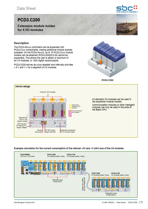
PCD3.C200Saia-Burgess Controls AG| 1Data Sheet31-682 ENG03 – Data Sheet – PCD3.C200PCD3.C200The PCD3.Mxxxx controllers can be expanded withPCD3.Cxxx components, making additional module sockets available. On the PCD3.Mxxx0, up to 15 PCD3.Cxxx module holders can be attached (PCD3.M3020/3120 cannot be expanded). This allows the user to attach a maximum of 64 I/O modules, or 1023 digital inputs/outputs.PCD3.C200 serves as a bus repeater and internally provides + 5 V and V + for a segment of I/O modules.Extension module holder for 4 I/O modulesDescriptionExample calculation for the current consumption of the internal +5V and +V (24V) bus of the I/O modules28.563.8125.813967.3100.53532.832.7Saia-Burgess Controls AG2 |31-682 ENG03 – Data Sheet – PCD3.C200Dimension DrawingPCD3.C200EarthSupply 24 VDCLED power okInternal supply of theLIO module carrier PCD3.C200+5VCLR 0V+V(16...24V)S u p p l y 24 V D CWhen planning PCD3 systems, it must be checked whether the two internal power supplies are not overloaded. This control is especially important when using analog, counting, and positioning and other special modules, as some of them consume a relatively large amount of power.❶ P ress lower part of housing ontomounting rail ❷ P ush up against the spring force upto the stop❸ H ook in over the upper edge of themounting rail and yield to the spring force⌧ F or safety, push the housing into themounting rail from top to bottom Check if the device is securly fixed.Dismounting from DIN railTo remove the housing, push upwards and pull out.Easy assembly of the moduleholders on DIN rail (1 × 35 mm)Saia-Burgess Controls AG| 331-682 ENG03 – Data Sheet – PCD3.C200PCD3 I/O modules are not hot-plug capable:• Carefully insert and remove the I/O modules after switching off the power supply (24V).The following aspects should be considered when planning PCD3 applications:• In keeping with lean automation, it is recommended to leave the first slot in the CPU basic module free for any subsequent expansions. This slot can accommodate simple I/O modules but also communication modules. • The total length of the I/O bus is limited by technical factors; the shorter, the better.The PCD3.C200 is used to extendthe I/O bus or for the internal power supply +5V and +V (24V) to a module segment.Please note the following rules:• Mandatory: I nsert a PCD3.C200 after the PCD3.M6893and after each cable (at the start of a row).• Use a maximum of five PCD3.K106/K116 cables. • Do not use more than six PCD3.C200s in a singleconfiguration, or the time delay will exceed the I/O access time.• If an application is mounted in a single row (max. 15 module holders), then after five PCD3.C100 a PCD3.C200 must be used to amplify the bus signal(unless the configuration ends with the fifth PCD3.C100). • If the application is mounted in multiple rows, therestricted length of cable means that only three module holders (1× PCD3.C200 and 2× PCD3.C100) may bemounted in one row.Insertion of I/O modulesTypesf PCD3.Axxx Digital output modulesf PCD3.Exxx D igital input modules f PCD3.Fxxx Communication modulesf PCD3.WxxxAnalogue input/output modulesOver 40 modules available with different functionalities ① Simple exchange of I/O modules31-682 ENG03 – Data Sheet – PCD3.C2004|Saia-Burgess Controls AG31-682 ENG03 – Data Sheet – PCD3.C200Saia-Burgess Controls AG|5Saia-Burgess Controls AGPCD3.C2006|Saia-Burgess Controls AGBahnhofstrasse 18 | 3280 Murten, SwitzerlandSubjects to change without notice. 31-682 ENG03 – 2020-07-17 – Datasheet – PCD3.C200Connecting plugPCD3.K010Extension cable 0.7 / 1.2 mPCD3.K106 / PCD3.K116Slot covers410475150 /410475020Screw terminal2-pole440549520。
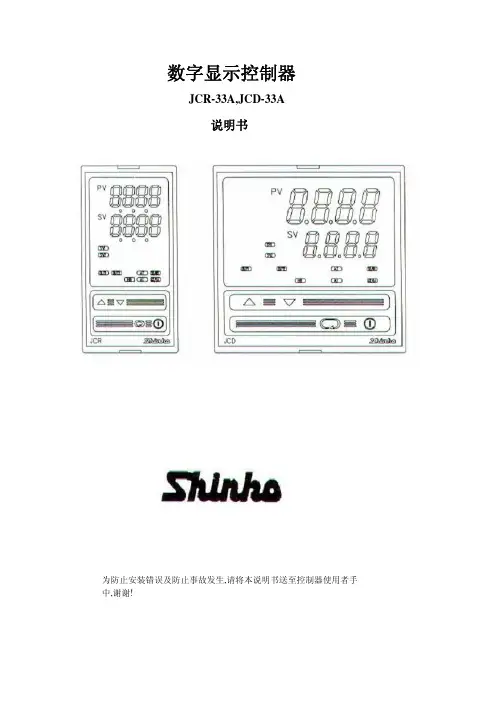
数字显示控制器JCR-33A,JCD-33A说明书为防止安装错误及防止事故发生,请将本说明书送至控制器使用者手中,谢谢!前言感谢使用本公司产品微电脑温度控制器[JCD-33A,或JCR-33A]本说明书是针对[JCD-33A,或JCR-33A]之设置方法,功能,操作方法等,予以说明,希望能详加阅读,充分理解后,使用本控制器。
为防止安装错误及防止事故发生,请将本说明书送至控制器使用者手中,谢谢!注意●本控制器应按说明书指定的规范使用。
若在规范外操作,将可能导致火灾或控制器故障,请注意。
●本控制器说明书内所记载的注意及警告事项,请严格遵守。
若未遵守其注意及警告事项,可能导致重大伤害事故,请注意。
●控制器需要定期维护。
●本说明书记载的内容,可能会有变更。
●本说明书尽可能予以周全叙述,如有不详或错误,尽请见谅,并予告知。
●为防止触电或出现故障,通电中请勿触及配线端子。
●如清洁本仪表,或锁紧端子时,请确认关闭控制器电源。
●本控制器如有污染,请用柔软干布擦拭干净。
不能使用香蕉水等浸渍类液体擦拭,因会导致本仪表变色及变形。
●显示器表面部分请勿以硬物刮敲。
●本控制器外壳使用耐燃性树脂制成,请勿将其安装在容易燃烧的物品附近,也不要在容易燃烧的物品上直接安装或与其接触。
●PID自整定(AT)请在试运行时执行。
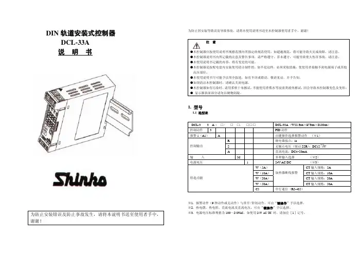
目次1.型号1.1型号的说明1.2额定输入1.3型号铭牌的表示方法2各部位名称和功能3安装到控制屏3.1场地的选定3.2外形尺寸图3.3控制屏开孔图3.4CT(电流互感器)外形尺寸图3.5安装4.配线4.1端子配置图4.2配线例5.设定5.1设定流程图5.2主设定模式主设定1(SV1)主设定2(SV2)5.3基本参数设定模式自整定(AT)或自动复位(Auto Reset)设定OUT1比例带设定OUT2冷却侧比例带设定积分时间设定微分时间设定ARW设定OUT1比例周期设定OUT2冷却侧比例周期设定温度报警1(A1)设定温度报警2(A2)设定HB(加热器断线报警)设定LA(回路异常报警)时间设定LA(回路异常报警)动作幅度设定5.4辅助功能设定模式1设定值锁定选择(SV)主设定值上限设定(SV)主设定值下限设定传感器校正设定通信协议选择仪表编号设定通信速度选择奇偶校选择停止位选择5.5辅助功能设定模式2传感器选择刻度范围上限值设定刻度范围下限值设定小数点位置选择PV滤波时间常数设定(OUT1)输出上限设定(OUT1)输出下限设定(OUT1)输出ON/OFF动作间距设定(OUT2)冷却侧动作模式选择(OUT2)冷却侧输出上限设定(OUT2)冷却侧输出下限设定重叠区/死区设定(OUT2)冷却侧输出ON/OFF动作间距设定温度报警1(A1)动作方式选择温度报警2(A2)动作方式选择温度报警1(A1)常开/常闭选择温度报警2(A2)常开/常闭选择温度报警1(A1)动作间距设定温度报警2(A2)动作间距设定温度报警1(A1)动作延迟时间设定温度报警2(A2)动作延迟时间设定正/逆动作选择AT偏差设定SVTC偏置设定SV2显示选择输入异常时输出状态选择“OUT/OFF键”功能选择5.6控制输出“OFF”功能5.7自动/手动控制功能5.8输出操作量显示6.运行7.动作说明7.1 OUT1动作图7.2加热器断线报警动作图【特选功能:W】7.3 OUT1 ON/OFF动作图7.4 OUT2(加热/冷却控制)动作图【特选功能:D□】 7.5温度报警1,2(A1,A2)动作图7.6 SV1/SV2外部切换动作图8.控制动作说明8.1 PID说明8.2控制器的PID自整定8.3自动复位(余差校正)9.1标准规格9.2特选功能规格10.寻找和排除故障10.1显示部分10.2“键操作”部分 10.3控制输出部分11.显示符号一览表1.1型号的说明在下划线的上面,请依需求填入“型号”、“控制输出”、“输入”、“特选功能”等字符。
, HEIDENHAIN®, Hiperface®,是商标持有人在相关国家注册的1关于本文件1.1目标人群该文件面向安装及运行该产品的人员。
此外也面向受委托在安全相关系统内规划和应用该产品的人员(符合 EN61508 标准的安全手册)。
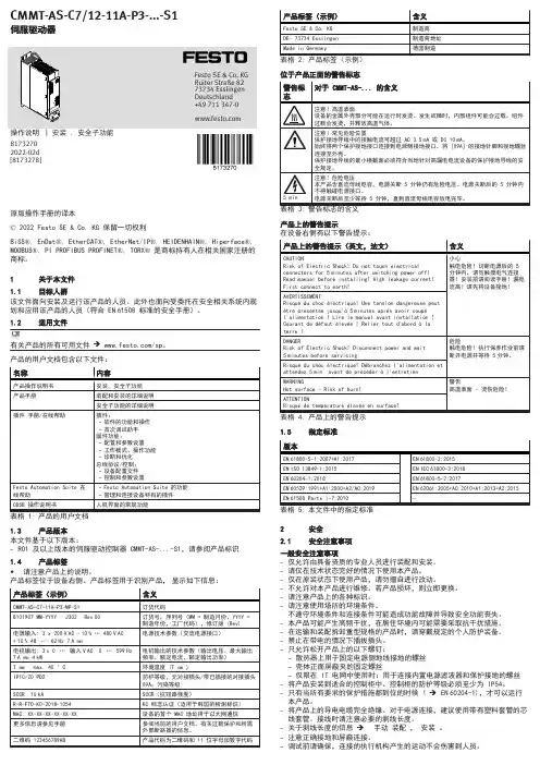
1.2适用文件产品的用户文档包含以下文件:1.3产品版本本文件基于以下版本:–R01 及以上版本的伺服驱动控制器 CMMT-AS-...-S1,请参阅产品标识1.4产品标签•请注意产品上的说明。
产品标签位于设备右侧。
产品标签用于识别产品,显示如下信息:位于产品正面的警告标志产品上的警告提示在设备右侧有以下警告提示:1.5指定标准2安全2.1安全注意事项一般安全注意事项–仅允许由具备资质的专业人员进行装配和安装。
–请仅在技术状态完好的情况下使用本产品。
–仅在原装状态下使用产品,请勿擅自进行改动。
–不允许对本产品进行维修。
若产品损坏,则立即更换。
–请注意产品上的各种标识。
–请注意使用场所的环境条件。
不遵守环境条件和连接条件可能造成功能故障并导致安全功能丧失。
–本产品可能产生高频干扰,在居住环境内可能需要采取抗干扰措施。
–在运输和装配拆卸重型规格的产品时,请穿戴规定的个人防护装备。
–禁止在带电的情况下插拔插头。
–只允许松开产品上的以下螺钉:–散热器上用于固定电源侧地线接地的螺丝–壳体正面屏蔽夹的固定螺丝–仅限在 IT 电网中使用时:用于连接内置电源滤波器和保护接地的螺丝–将产品安装到适合的控制柜中。
控制柜的防护等级必须至少为 IP54。
–只有当所有要求的保护措施都到位的时候 ( è EN60204-1),才可以运行本产品。
–将产品上的导电电缆完全绝缘。
对于电源连接,建议使用带有塑料套管的芯线套管。
接线时请注意必要的剥线长度。
–关于剥线长度的信息 è 手动 装配 , 安装 。
–注意正确接地和屏蔽连接。
–调试前请确保,连接的执行机构产生的运动不会伤害到人员。
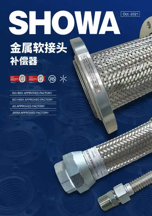
SHOWA 补偿器金属软接头目 录科目目录 ................................................................................................ 金属软接头..................................................................................EXF 110 .......................................................................................... EXF 115 .......................................................................................... EXF 122 .......................................................................................... EXS 210 .......................................................................................... EXS 255 .......................................................................................... 补偿器.........................................................................................EXDZ .............................................................................................. EXFZ .............................................................................................. EXWZ ............................................................................................. 软管和软网的尺寸及性能................................................................... 有变位时软管长度计算...................................................................... 正确的安装方式................................................................................ 法兰连接尺寸................................................................................... 单位换算表...................................................................................... 资料 不锈钢耐腐蚀表........................................................................ 软管产品选型、安装及实用注意事项.................................................... 0102-06020304050607-1207091113151819222328页码具有优异耐弯曲性能的焊接组装法兰连接形式。

【关键字】精品大量钻孔机说明书篇一:全自动中心钻孔机操作说明书使用及维护手册全自动圆锯打中心孔专用机HJ.A13027使用前请务必仔细阅读本手册错误操作十分危险操作人员必须熟知并遵守安全规则目录一、设备简介及适用范围 (14)二、结构与功能描述 (5)三、操作流程 (15)四、操作面板及触摸屏说明 (18)五、故障排除方式 (35)六、现场环境及工件要求 (38)附1、电气原理图安全注意事项? 始终遵守安全注意事项可以防止意外事故及潜在危险的发生。
? 在本使用手册中,安全等级分类如下:不正确的操作可能导致严重的人身伤害或死亡。
危险注意不正确的操作可能导致轻微的人身伤害或物体硬件的损坏。
在本说明书中,全篇使用以下两个图标以使你能明白安全注意事项。
在某些确定的条件下可以识别导致人身伤害的危险。
由于危险电压可能已出现,所以应有意识地特别注意。
禁止手伸入。
在某些确定的条件下可以识别潜在的危险。
仔细阅读相关信息并遵守相关指令。
? 为了方便取阅使用说明书,请就近保存。
? 仔细阅读本说明书,使您的设备性能达到最佳化,并确保安全地使用。
1. 设备装卸、安装及接线? 装卸设备注意人生安全,勿以工作台来起吊设备,勿使设备受到撞击。
? 先安装设备,再进行接线,否则,你可能受到电击或其它伤害。
? 安装设备需注意调整每个承重脚均衡承重,并保证机身水平。
? 设备电源为三相AC380V 50Hz,电缆大于10mm×5。
? 2? 不正确的端子接线可能引起设备的损坏。
? 只有受过专业培训的人才可以对设备进行接线和检查。
2. 安全规则? 使用前先对设备各处进行详细地检查,清除异物,保证设备的正常运转; 检查是否满足生产工艺要求,确认无误后开始生产。
? 保养设备时应关断电源,以免意外伤害。
? 生产场地应有良好的通风。
3. 维护,检查与零件更换? 定期检查。
著作权保证本操作手册应作机密处理。
只有经过授权的人员可以使用。
只有经过HONGJI 书面许可,才可以将本档交会第三者。

使 用 说 明 书低速离心机安徽中科中佳科学仪器有限公司※ 安装、使用产品前,请阅读此使用说明书! 医疗器械许可证编号: 皖食药监械生产许20150020 号 医疗器械生产备案号: 皖合食药监械生产备20150014号 产品技术要求编号:皖合械备20150107号 产品备案号: 皖合械备20150107号 适用机型:LC-4010 LC-4012 LC-4014 LC-4016 KDC-40 版本号:V2.016.11目录前言1.11.21.34.14.25.15.25.35.45.5附录重要提示●严禁离心易燃、易爆、有剧烈化学反应及腐蚀性的化学品,否则会腐蚀腔体和转头等配件,严重时会导致机器损坏并危及人身安全!●离心机水平转头、吊杯正常使用寿命为三年,过期后应立即联系生产单位更换新转头,否则可能损坏机器并危及人身安全!●每次开机前,应认真检查转头的压紧螺母是否旋紧!●在使用离心机时,请务必使用单相三孔电源插座,并确保其可靠接地!●离心机工作时,应确保其工作电压在规定的范围内。
当离心机不能正常工作时,首先应检查电源电压是否正常!●为确保离心机及操作者安全,仪器运转时,转速的设定值不得超过其最高转速!必须在离心机完全停止状态下才可开门或应急解锁!●离心机断电后,请等待足够的时间(3min以上),方可再次打开电源!●离心样品装载前必须配平,各离心样品质量偏差不得大于5g,且要对称放入样品插孔中,如样品数量不成偶数,可用空试管加水配平后凑足。
否则,离心时会产生机器振动,并可能损坏机器!●离心样品平衡放置后,应双手同时用力关好门盖并确认门盖是否关好。
如门盖未关好,仪器将不能正常启动,此时应打开门盖再次重新关好门盖。
●为避免发生意外,离心机在使用水平转头时必须如下图放置吊杯,且吊杯内提篮的两耳连线必须向着离心电机轴的中心!●购买中科中佳离心机产品后,请及时登录网站进行“用户登记”,享受更全面服务。
!标识意义:注意!查阅随机文件。
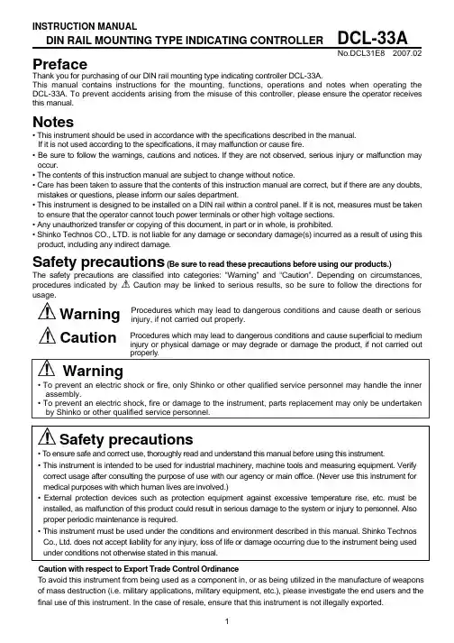
INSTRUCTION MANUALDIN RAIL MOUNTING TYPE INDICATING CONTROLLERDCL-33ANo.DCL31E8 2007.02PrefaceThank you for purchasing of our DIN rail mounting type indicating controller DCL-33A. This manual contains instructions for the mounting, functions, operations and notes when operating the DCL-33A. To prevent accidents arising from the misuse of this controller, please ensure the operator receives this manual.Notes• This instrument should be used in accordance with the specifications described in the manual. If it is not used according to the specifications, it may malfunction or cause fire. • Be sure to follow the warnings, cautions and notices. If they are not observed, serious injury or malfunction may occur. • The contents of this instruction manual are subject to change without notice. • Care has been taken to assure that the contents of this instruction manual are correct, but if there are any doubts, mistakes or questions, please inform our sales department. • This instrument is designed to be installed on a DIN rail within a control panel. If it is not, measures must be taken to ensure that the operator cannot touch power terminals or other high voltage sections. • Any unauthorized transfer or copying of this document, in part or in whole, is prohibited. • Shinko Technos CO., LTD. is not liable for any damage or secondary damage(s) incurred as a result of using this product, including any indirect damage. (Be sure to read these precautions before using our products.) The safety precautions are classified into categories: “Warning” and “Caution”. Depending on circumstances, procedures indicated by Caution may be linked to serious results, so be sure to follow the directions for usage.Safety precautionsWarning Caution WarningProcedures which may lead to dangerous conditions and cause death or serious injury, if not carried out properly. Procedures which may lead to dangerous conditions and cause superficial to medium injury or physical damage or may degrade or damage the product, if not carried out properly.• To prevent an electric shock or fire, only Shinko or other qualified service personnel may handle the inner assembly. • To prevent an electric shock, fire or damage to the instrument, parts replacement may only be undertaken by Shinko or other qualified service personnel.Safety precautions• To ensure safe and correct use, thoroughly read and understand this manual before using this instrument. • This instrument is intended to be used for industrial machinery, machine tools and measuring equipment. Verify correct usage after consulting the purpose of use with our agency or main office. (Never use this instrument for medical purposes with which human lives are involved.) • External protection devices such as protection equipment against excessive temperature rise, etc. must be installed, as malfunction of this product could result in serious damage to the system or injury to personnel. Also proper periodic maintenance is required. • This instrument must be used under the conditions and environment described in this manual. Shinko Technos Co., Ltd. does not accept liability for any injury, loss of life or damage occurring due to the instrument being used under conditions not otherwise stated in this manual. Caution with respect to Export Trade Control Ordinance To avoid this instrument from being used as a component in, or as being utilized in the manufacture of weapons of mass destruction (i.e. military applications, military equipment, etc.), please investigate the end users and the final use of this instrument. In the case of resale, ensure that this instrument is not illegally exported. 11. Installation precautions CautionThis instrument is intended to be used under the following environmental conditions (IEC61010-1): Overvoltage category , Pollution degree 2 Ensure the mounting location corresponds to the following conditions: • A minimum of dust, and an absence of corrosive gases • No flammable, explosive gases • No mechanical vibrations or shocks • No exposure to direct sunlight, an ambient temperature of 0 to 50 (32 to 122 ) that does not change rapidly, and without icing • An ambient non-condensing humidity of 35 to 85%RH • No large capacity electromagnetic switches or cables through which large current is flowing. • No water, oil or chemicals or where the vapors of these substances can come into direct contact with the unit • Take note that ambient temperature of this unit must not exceed 50 (122 ) if mounted within the control panel. Otherwise the life of electronic components (especially electrolytic capacitors) may be shortened. Note: Avoid setting this instrument directly on or near flammable material even though the case of this instrument is made of flame-resistant resin.2. Wiring precautions Caution• Do not leave bits of wire in the instrument, because they could cause fire or malfunction. • Do not apply a commercial power source to the sensor which is connected to the input terminal nor allow the power source to come into contact with the sensor. • Insert the connecting cable into the designated connector securely. Not doing so could cause malfunction due to imperfect contact. • Connect the AC power to the designated terminal as is written in this instruction manual. Otherwise it may burn or damage the DCL-33A. • Use correct fitting ferrules with an insulation sleeve for the terminal screw when wiring the DCL-33A. • Tighten the terminal screw to within the specified torque. If excessive force is applied to the screw when tightening, the terminal screw or case may be damaged. • For a 24V AC/DC power source, do not confuse polarity when using direct current (DC). • This instrument does not have a built-in power switch, circuit breaker or fuse. It is necessary to install them near the controller. (Recommended fuse: Time-lag fuse, rated voltage 250V AC, rated current 2A)3. Running and maintenance precautions Caution• It is recommended that PID auto-tuning be performed on the trial run. • Do not touch live terminals. This may cause electric shock or problems in operation. • Turn the power supply to the instrument OFF when retightening the terminal or cleaning. Working or touching the terminal with the power switched ON may result in severe injury or death due to Electric Shock. • Use a soft, dry cloth when cleaning the instrument. (Alcohol based substances may tarnish or deface the unit.) • As the display section is vulnerable, do not strike or scratch it with a hard object or press hard on it. Characters used in this manual Indication Number, / -1 0 1 Indication Alphabet A B C Indication Alphabet N O P2 D Q3 E R4 F S5 G T 26 H U7 I V8 J W9 K X L Y M Z1. Model1.1 Model Series name: DCL-300 (W22.5 x H75 x D100mm) PID Selectable by keypad *1 R Relay contact: 1a OUT S Non-contact voltage (for SSR): 12+2 -0V DC (Control output) A DC current: 4 to 20mA DC Multi-range *2 Input M 100 to 240V AC (standard) Supply voltage 1 24V AC/DC *3 W (5A) CT rated current: 5A W (10A) CT rated current: 10A Heater burnout alarm Option W (20A) CT rated current: 20A W (50A) CT rated current: 50A C5 Serial communication EIA RS-485 *1: Alarm type (9 types and No alarm) and status Energized/Deenergized can be selected by keypad. *2: Thermocouple, RTD, DC current and DC voltage can be selected by keypad. *3: Standard supply voltage is 100 to 240V AC. Enter “1” after the input code only when ordering 24V AC/DC. 1.2 How to read the model label The model label is attached to the left side of the case. For Heater burnout alarm output, CT rated current value is written in the bracket ( ). DCL - 3 Control action Alarm 3 A3 A ,(1) (2)(1) Model, Supply voltage (Enter “1” only for 24V AC/DC), Option (e.g.) Relay contact output, Multi-range input (2) Serial number(Fig. 1.2-1)2. Name and functions of the sections(1) EVT indicator The red LED lights when Event output (Alarm, Loop break alarm or the Heater burnout alarm option) is ON. (2) OUT indicator The green LED lights when OUT (control output) is ON. For DC current output type, this flashes in 0.25 second cycles corresponding to the output MV (manipulated variable). (3) T/R indicator The yellow LED flashes during serial communication TX output (transmission). (4) AT (auto-tuning) indicator The yellow LED flashes while auto-tuning is being performed. (5) PV display: Indicates the PV (process variable) or setting characters (in each setting mode) with a Red LED. (6) SV display: Indicates the SV (desired value) or each set value (in each setting mode) with a Green LED. ): Increases the numeric value. (7) Increase key ( ): Decreases the numeric value. (8) Decrease key ( ):Switches the setting mode or registers set values. (9) Mode key ( ) key.] [Registers set values by pressing the Mode ( (10) Sub-mode key (unmarked) Brings up Auxiliary function setting mode 2 in combination with the Mode ((1) (2) (5) (6) (7) (8)(3) (4)(9) (10)) key.(Fig. 2-1)CautionWhen setting the specifications and functions of this controller, connect terminals 1 and 2 for power source first, then set them referring to “5. Setup” before performing “3. Mounting to the control panel” and “4. Wiring”. 33. Mounting to the control panel3.1 Site selection This instrument is intended to be used under the following environmental conditions (IEC61010-1): Overvoltage category , Pollution degree 2 Ensure the mounting location corresponds to the following conditions: • A minimum of dust, and an absence of corrosive gases • No flammable, explosive gases • Few mechanical vibrations or shocks • No exposure to direct sunlight, an ambient temperature of 0 to 50 (32 to 122 ) without rapid change, and without icing • An ambient non-condensing humidity of 35 to 85%RH • No large capacity electromagnetic switches or cables through which large current is flowing • No water, oil or chemicals or where the vapors of these substances can come into direct contact with the controller • Take note that ambient temperature of this unit must not exceed 50 (122 ) if mounted within the control panel. Otherwise the life of electronic components (especially electrolytic capacitors) may be shortened. 3.2 External dimensions (Unit: mm)DIN rail7597 22.5 100 4(Fig. 3.2-1)3.3 CT (Current transformer) external dimensions (Unit: mm)CTL-6S (for 20A) (Fig. 3.3-1) 3.4 Mounting to and removal from the DIN railCTL-12-S36-10L1U (for 50A)Caution• Mount the DIN rail horizontally. When the DIN rail is mounted vertically, be sure to use commercially available fastening plates at both ends of the DCL-33A series. However, if the DIN rail is mounted horizontally in a position susceptible to vibration or shock, the fastening plates must be used as well. • To remove this instrument, a flat blade screwdriver is required for pulling down the lever. Never turn the screwdriver when inserting it into the release lever. If excessive power is applied to the lever, it may break.4• Recommended fastening plateManufacturer Omron corporation IDEC corporation Matsushita electric works, LTD. End plate Fastening plate Fastening plate Model PFP-M BNL6 ATA4806Mounting to the DIN rail (Fig. 3.4-1) First, hook 1 of the DCL-33A on the upper side of the DIN rail. Second, making 1 part of the DCL-33A as a support, fit the lower part 2 of the DCL-33A to the DIN rail. DCL-33A will be completely fixed to DIN rail with a “Click” sound. Removal from the DIN rail (Fig. 3.4-2) 1 Insert a flat blade screwdriver into the release lever, and pull it down. 2 The lock to the DIN rail will be released, then remove the unit from the DIN rail. Be sure to hold onto the unit or it will drop to the ground.1Release lever22(Fig. 3.4-1) Mounting1(Fig. 3.4-2) Removal4. Wiring WarningTurn the power supplied to the instrument OFF before wiring or checking it. Working or touching the terminal with the power switched ON may result in severe injury or death due to Electric Shock.Caution• Do not leave bits of wire in the DCL-33A when wiring, because they could cause fire or malfunction. • Insert the connecting cable into the designated connector securely. Not doing so could cause malfunction due to imperfect contact. • Connect the AC power to the designated terminal as is written in this instruction manual. Otherwise it may burn and damage the DCL-33A. • Tighten the terminal screw with the specified torque. Excessive force could damage the terminal screw and deface the case. • Use a thermocouple and compensating lead wire that corresponds to the sensor input specification of this unit. • Use the 3-wire RTD that corresponds to the sensor input specification of this unit. • When using DC voltage and current inputs, be careful not to confuse polarity when wiring. • For a 24V AC/DC power source, do not confuse polarity when using direct current (DC). • Keep input wires (Thermocouple, RTD, etc.) away from power source and load wires when wiring. • Do not apply a commercial power source to the sensor connected to the input terminal nor allow the power source to come into contact with the sensor. • To prevent the unit from harmful effects of unexpected level noise, it is recommended that a surge absorber be installed between the electromagnetic switch coils. • This unit does not have a built-in power switch, circuit breaker or fuse. Therefore it is necessary to install them in the circuit near the external unit. (Recommended fuse: Time-lag fuse, Rated voltage 250V AC, Rated current 2A) 5When using ferrules, use the following ferrules and crimping pliers made by Phoenix Contact GMBH &CO.• Recommended ferrules and tightening torqueTerminal number 1 to 4 Terminal screw M2.6 Ferrules with insulation sleeve AI 0.25-8 YE AI 0.34-8 TQ AI 0.5-8 WH AI 0.75-8 GY AI 1.0-8 RD AI 1.5-8 BK AI 0.25-8 YE AI 0.34-8 TQ AI 0.5-8 WH Conductor cross sections 0.2 to 0.25mm2 0.25 to 0.34mm2 0.34 to 0.5mm2 0.5 to 0.75mm2 0.75 to 1.0mm2 1.0 to 1.5mm2 0.2 to 0.25mm2 0.25 to 0.34mm2 0.34 to 0.5mm2 Tightening torque 0.5 to 0.6N•m Crimping pliers CRIMPFOX ZA3 CRIMPFOX UD65 to 9M2.00.22 to 0.25N•m• Terminal arrangementBottom of the unit • MAIN OUTPUT: Control output • EVENT OUTPUT: Outputs when Alarm, Loop break alarm or Heater burnout alarm (option) is activated. • RS-485: Serial communication • TC : Thermocouple • RTD : Resistance temperature detector • DC : DC current or DC voltage For DC current input, 50 shunt resistor must be connected between input terminals.Communication C5 (RS-485)CT input (W)(Fig. 4-1)• Option: Heater burnout alarm This alarm is not available for detecting current under phase control. Use the current transformer (CT) provided, and pass a lead wire of the heater circuit into a hole of the CT. When wiring, keep the CT CT wire away from any AC source or load wires to avoid the external interference.CT input socket Power supplyHeater(Fig. 4-2)65. SetupThe sensor input character and temperature unit are indicated on the PV display for approx. 3 seconds after the power is turned on, and the input range high limit value is indicated on the SV display. (Table 5-1) (If any other value is set during the Scaling high limit setting, it is indicated on the SV display.) During this time all outputs and the LED indicators are in OFF status. After that, the control starts indicating PV (process variable) on the PV display, and SV (desired value) on the SV display. (Table 5-1) Input K J R S B E T N PLC (W/Re5-26) Pt100 JPt100 4 to 20mA DC 0 to 20mA DC 0 to 1V DC 0 to 5V DC 1 to 5V DC 0 to 10V DC Input range –200 to 1370 –320 to 2500 –199.9 to 400.0 –199.9 to 750.0 –200 to1000 –320 to1800 0 to 3200 0 to 1760 0 to 1760 0 to 3200 0 to 1820 0 to 3300 –200 to 800 –320 to 1500 –199.9 to 400.0 –199.9 to 750.0 –200 to 1300 –320 to 2300 0 to 1390 0 to 2500 0 to 2315 0 to 4200 –199.9 to 850.0 –199.9 to 999.9 –200 to 850 –300 to 1500 –199.9 to 500.0 –199.9 to 900.0 –300 to 900 –200 to 500 –1999 to 9999 *1, *2 –1999 to 9999 *1, *2 –1999 to 9999 *1 –1999 to 9999 *1 –1999 to 9999 *1 –1999 to 9999 *1 Resolution 1 ( ) 0.1 ( ) 1 ( ) 1 ( ) 1 ( ) 1 ( ) 1 ( ) 0.1 ( ) 1 ( ) 1 ( ) 1 ( ) 0.1 ( ) 1 ( ) 0.1 ( ) 1 ( ) 1 1 1 1 1 1*1: Input range and decimal point place can be changed. *2: 50 shunt resistor (sold separately) must be connected between the input terminals.75.1 Operation flowchart Outline of operation procedureSet Input type, Alarm (type, value, etc.) and SV (desired value), following the procedures below. Setting item numbers (1) to (8) are indicated on the flowchart. [Step 1 Operation before run] Turn the load circuit power OFF, and turn the power supply to the DCL-33A ON. [Step 2 Auxiliary function Set Input type and Alarm type, etc. in Auxiliary function setting mode 2. setting mode 2] (1) Input type: Select an input type. Refer to “Input type (character indication) and range” on page 10. (2) Alarm type: Select an alarm type. Refer to “Alarm type” on page 10. [If an alarm type except for “ ” is selected, items (3) to (6) will be indicated and they can be set if necessary.] Note: If an alarm type is changed, the alarm set value becomes 0 (0.0). Therefore it is necessary to set it again. (3) Alarm action Energized/Deenergized: Select Alarm action Energized or Deenergized. (4) Alarm HOLD function: Select either Alarm Not holding or Alarm Holding. (5) Alarm hysteresis: Set Alarm hysteresis. (6) Alarm action delayed timer: Set Alarm action delayed timer. [Step 3 Sub setting mode] (7) Alarm value: Set alarm action point in the Sub setting mode. [Step 4 Main setting mode] (8) SV: Set SV (Desired value) in the Main setting mode. [Step 5 Run] Turn the load circuit power ON. Control action starts so as to keep the control target at the SV (Desired value).Press the PV/SV display Press the key for approx. 3sec. Press key. Output MV (manipulated variable) indicationPress the (8) SV (Desired value) PV SV SVkey.Press the ATkey while holding down thekey.for approx. 3sec while holding down.[Main setting mode]PV[Sub setting mode]SV[Auxiliary function setting mode 1]Set value lockPV SVSelection• If AT is cancelled during the process, PID values revert to previous value. • Set the value with , keys. • ON/OFF action when set to 0 or 0.0Reverts to PV/SV display.PVOUT proportional bandSVSelection• Make a selection with , keys. • If Lock 1 or Lock 2 is selected, AT does not work. • Be sure to select Lock 3 when frequently changing set values via Serial communication.Set valueSensor correction Integral timePV SVExplanation of • ifkeySet value• Set the value with , keys. • Setting the value to 0 disables the function.PVSVSet value• Set the value with,keys.Communication protocolPV SV• Make a selection with,keys.: This means that is pressed, the setPVSelectionDerivative timeSVvalue is saved, and the controller proceeds to the next setting item. • If the key is pressed for approx. 3sec, the controller reverts to the PV/SV display mode from any mode.Set value• Set the value with , keys. • Setting the value to 0 disables the function.Instrument numberPV SVSet value• Set the value with,keys.ARWPV SVSet value, • Set the value with • Available for PID actionkeys. Communication speedPV SVSelection• Make a selection with,keys.OUT proportional cyclePV SVSet value• Set the value with , keys. • Not available for DC current output or if OUT is in ON/OFF actionParityPV SVSelection, keys. • Make a selection with is selected • Not available if during Communication protocol selectionManual resetPV SV• Set the value with , keys. • Available for P or PD action Stop bitPV SVSet valueSelection(7)PVAlarm valueSVSet value• Set the value with , keys. is selected • Not available if during Alarm type selection• Make a selection with , keys. is selected • Not available if during Communication protocol selectionReverts to the PV/SV display.Heater burnout alarm value PV SV . Set value • Set the value with , keys. • Setting the value to 0.0 disables the function.Loop break alarm timePV SVSet value, keys. • Set the value with • Setting the value to 0 disables the function.Setting items with dotted lines are optional, and they appear only when the options are added.Loop break alarm spanPV SVSet value, keys. • Set the value with • Setting the value to 0 disables the function.Reverts to the PV/SV display.85.2 Main setting mode Character Name, Description, Setting range Default value SV 0 • Sets the SV for control target. • Scaling low limit value to scaling high limit value (For DC input, the placement of the decimal point follows the selection) 5.3 Sub setting mode Character Name, Description, Setting range Default value AT setting • Performs PID auto-tuning. However, if PID auto-tuning does not finish after 4 hours, it will be automatically shut down. • : PID auto-tuning Cancel : PID auto-tuning Perform OUT proportional band setting 2.5% • Sets the proportional band. • The control action becomes ON/OFF when set to 0.0 • Setting range: 0.0 to 110.0% Integral time setting 200 seconds • Sets the integral time. • Setting the value to 0 disables this function. • Not available for ON/OFF action. • Setting range: 0 to 1000 seconds Derivative time setting 50 seconds • Sets the derivative time. • Setting the value to 0 disables this function. • Not available for ON/OFF action. • Setting range: 0 to 300 seconds ARW (Anti-reset windup) setting 50% • Sets anti-reset windup. • Available only for PID action. • Setting range: 0 to 100% OUT proportional cycle setting 30 seconds • Sets the proportional cycle value for the control output (OUT). or 3 seconds • Not available for ON/OFF action or DC current output. • Setting range: 1 to 120 seconds Manual reset setting 0.0 • Sets the reset value manually. • Available only for P and PD action. • Proportional band converted value (For DC input, the placement of the decimal point follows the selection) Alarm value setting 0 • Sets the action point for the alarm output. • Setting the value to 0 or 0.0 disables this function (excluding Process high and Process low alarms) When Loop break alarm and Heater burnout alarm are applied together, they utilize common output terminals. • Not available if No alarm action is selected during Alarm type selection. • See (Table 5.3-1) (p.11). (For DC input, the placement of the decimal point follows the selection.) Heater burnout alarm setting 0.0A . and • Sets the heater current value for Heater burnout alarm. XX.X • Setting the value to 0.0 disables this function. alternating • Upon returning to set limits, the alarm will stop. display When Alarm and Loop break alarm are applied together, they utilize common output terminals. • Available only when Heater burnout alarm is added. • Rated current 5A : 0.0 to 5.0A Rated current 10A: 0.0 to10.0A Rated current 20A: 0.0 to 20.0A Rated current 50A: 0.0 to 50.0A 9Input type (character indication) and range :K –200 to 1370 :K –320 to 2500 –199.9 to 400.0 –199.9 to 750.0 :J –200 to 1000 :J –320 to 1800 :R 0 to 1760 :R 0 to 3200 :S 0 to 1760 :S 0 to 3200 :B 0 to 1820 :B 0 to 3300 :E –200 to 800 :E –320 to 1500 :T –199.9 to 400.0 :T –199.9 to 750.0 :N –200 to 1300 :N –320 to 2300 : PL0 to 1390 : PL0 to 2500 : C(W/Re5-26) 0 to 2315 : C(W/Re5-26) 0 to 4200 : Pt100 –199.9 to 850.0 : Pt100 –199.9 to 999.9 : JPt100 –199.9 to 500.0 : JPt100 –199.9 to 900.0 : Pt100 –200 to 850 : Pt100 –300 to 1500 : JPt100 –200 to 500 : JPt100 –300 to 900 : 4 to 20mA DC –1999 to 9999 : 0 to 20mA DC –1999 to 9999 : 0 to 1V DC –1999 to 9999 : 0 to 5V DC –1999 to 9999 : 1 to 5V DC –1999 to 9999 : 0 to 10V DC –1999 to 9999Alarm type (High limit alarm): The alarm action is deviation setting from the SV. The alarm is activated if the input value reaches the high limit set value. (Low limit alarm): The alarm action is deviation setting from the SV. The alarm is activated if the input value goes under the low limit set value. (High/Low limits alarm): Combines High limit and Low limit alarm actions. When input value reaches high limit set value or goes under the low limit set value, the alarm is activated. (High/Low limit range alarm): When input value is between the high limit set value and low limit set value, the alarm is activated. (Process high alarm), (Process low alarm): Within the scale range of the controller, alarm action points can be set at random and if the input reaches the randomly set action point, the alarm is activated. (High limit alarm with standby), (Low limit alarm with standby), (High/Low limits alarm with standby): When the power to the controller is turned on, even if the input enters the alarm action range, the alarm is not activated. (If the controller is allowed to keep running, once the input exceeds the alarm action point, the standby function will be released.)Press the key for approx. 3sec while holding down the key. [Auxiliary function setting mode 2] (1) Input typePV SVSelection• Make a selection with • Default value:,keys.(6)Alarm action delayed timerPV SVSet value, keys. • Set the value with is selected during • Not available if Alarm type selectionScaling high limitPV SV• Set the value with,keys. Direct/Reverse controlPV SVSet valueSelection• Make a selection with • Default value:,keys.Scaling low limitPV SV• Set the value with,keys. AT biasPV SVSet valueSet value, keys. • Set the value with • Available for thermocouple, RTD inputDecimal point placePV SVSelection, keys. • Make a selection with • Available for DC current, DC voltage inputPVSVTC biasSV• Set the value with,keys.Set valuePV filter time constantPV SV• Set the value with,keys.Set valueOutput status selection when input abnormalPV SV• Make a selection with , keys. • Available only when input is DC current and DC voltage with DC current output SelectionOUT high limitPV SVSet value• Set the value with , keys. • Not available for ON/OFF actionController/ConverterPV SVSelection• Make a selection with , keys. • Available for DC current outputOUT low limitPV SVSet value, keys. • Set the value with • Not available for ON/OFF actionReverts to the PV/SV display.OUT ON/OFF action hysteresisPV SVSet value• Set the value with , keys. • Available for ON/OFF action(2)Alarm typePV SVSelection• Make a selection with • Default value:,keys.(3)Alarm action Energized/DeenergizedPV SVSelection• Make a selection with • Not available if Alarm type selection, keys. is selected during(4)Alarm HOLD functionPV SVSelection• Make a selection with • Not available if Alarm type selection, keys. is selected during(5)Alarm hysteresisPV SVSet value• Set the value with , keys. is selected during • Not available if Alarm type selection10Loop break alarm time setting 0 minutes• Sets the action time to assess the Loop break alarm.• Setting the value to 0 disables this function.• When Alarm and Heater burnout alarm are applied together, they utilize commonoutput terminals.• Setting range:0 to 200 minutesLoop break alarm span setting 0• Sets the action span to assess the Loop break alarm.• Setting the value to 0 disables this function.• When Alarm and Heater burnout alarm are applied together, they utilize commonoutput terminals.• Thermocouple, RTD input: 0 to 150() or 0.0 to 150.0()DC input: 0 to 1500 (The placement of the decimal point follows the selection) (Table 5.3-1)Alarm type Setting rangeHigh limit alarm –(Scaling span) to scaling spanLow limit alarm –(Scaling span) to scaling spanHigh/Low limits alarm 0 to scaling spanHigh/Low limit range alarm 0 to scaling spanProcess high alarm Scaling low limit value to scaling high limit valueProcess low alarm Scaling low limit value to scaling high limit valueHigh limit alarm with standby –(Scaling span) to scaling spanLow limit alarm with standby –(Scaling span) to scaling spanHigh/Low limits with standby 0 to scaling spanMinimumnegative value:–199.9 or –1999Maximumpositive value:999.9 or 99995.4 Auxiliary function setting mode 1Character Name,Description, Setting range Default value Set value lock selection Unlock• Locks set values to prevent setting errors.The setting item to be locked is dependent on the selection.• Auto-tuning cannot be carried out if Lock 1 or Lock 2 is selected.• Be sure to select Lock 3 when changing the set values frequently viacommunication function considering the life of non-volatile memory.• (Unlock): All set values can be changed.(Lock 1): None of set values can be changed.(Lock 2): Only main setting mode can be changed.(Lock 3): All set values except Input type and Controller/Converterfunction can be changed. However, changed values revert totheir previous values after power-off because they are notsaved in the non-volatile memory.Do not change any setting item in Auxiliary function settingmode 2. If any item in Auxiliary function setting mode 2 ischanged, it will affect other setting items such as the SVand Alarm value.Sensor correction setting 0.0• Sets the sensor correction value of the sensor.• Thermocouple and RTD input: –100.0 to 100.0()DC input: –1000 to 1000 (The placement of the decimal point follows the selection.)Communication protocol selection Shinko protocol• Selects communication protocol.• Available only when the C5 option is added.• : Shinko protocol, : Modbus ASCII mode, : Modbus RTU modeInstrument number setting 0• Sets an individual instrument number to each DCL-33A when connecting pluralDCL-33A units in serial communication.• Available only when the C5 option is added.• Setting range: 0 to 95Communication speed selection 9600bps• Selects the speed in accordance with the host computer.• Available only when the C5 option is added.• : 2400bps, : 4800bps, : 9600bps, : 19200bps。
CHC-400A 激光切割激光切割高度控制器高度控制器使用说明书使用说明书深圳迈卡特数控技术有限公司公司地址:深圳市宝安九区宝民一路白金酒店公寓519 公司电话:************* 传真:*************公司网址: Email :****************QQ :857950609目 录录一、 简介简介 (22)二、 技术指标技术指标……………………………………………………………………………………………………………………………………………………… 2 2三、 外形及安装外形及安装 (33)四、 操作面板及功能操作面板及功能 (55)五、 接口电路接口电路 (66)六、 调试调试 (7)七、 故障维护故障维护 (8)*使用调高器之使用调高器之前前,请仔细阅读说明书请仔细阅读说明书**一、简介CHC-400A 是专为激光切割设计的。
CHC-400A 电容式调高系统是一个闭环控制系统,它包括位置信号检测、信号处理变换、逻辑控制、电机驱动四个部分,CHC-400A可对割炬进行自动高度控制,适用于数控激光切割机床。
CHC-400A 的输出控制为直流永磁电机。
电机的驱动采用脉宽调制(PWM)方式。
客户在选配电机及变速箱时,割炬额定升降速度应为3000mm/min左右。
二、技术指标供电电压:AC24V±10%,50Hz~60Hz升降电机:DC24V 永磁直流电机输出控制方式:PWM无极调速输出电流:1A-4A工作温度:调高器-10∽60℃,高频同轴电缆:-10∽200℃精度:±0.05mm精度内的调节范围:距工件表面1mm — 10mm最大输出功率:60W高频电缆长度(HF-cable):500-800mm主体外形尺寸(长X 宽X 高):150mmX133mmX47mm断线保护功能:HF 高频电缆部分外观及安装三:外观及安装调高器外形视图:下面分别给出调高器的前视图、后视图及仰视图。
Parts Manual cFor Technical Assistance call: 800-227-2233, Fax: 888-329-8207 To Order Parts call: 888-227-2233, Fax: 888-329-0234Single-Double Pallet Handler55E-FDS-871ModelSerial Number cascadeாcorporationPublicationsDecals55EPART NO. DESCRIPTION 214269 Parts Manual 213580 Operator’s Guide213372 Installation Instructions 679929 Tool Catalog673964 Literature Index Order FormCommon PartsREF QTY PART NO.DESCRIPTION72210489Rod End Anchor s 84768303Capscrew, M10 x 35 s 94210140Bearing Retainer1012787375Capscrew, M8 x 20 GR 8.8111214631T-Bar – Lower121220009Retainer/Stop – RH 131220008Retainer/Stop – LH 1444730-1050Bearing Segment1514211689Capscrew, M12 x 30 GR 10.9161220143T-Bar – Upper171216838Valve Assembly v 181211456Manifold196768208Capscrew, M8 x 25204768795Capscrew, M8 x 30211675548Sideshift Cylinder q 222672018Upper Bearing 232208350Lower Bearing 241218208Spacer Block252767615Capscrew, M10 x 255See Frame Cylinder page for parts breakdown.v See Valve Assembly – Class III page for parts breakdown.s Included in Cylinder Rod Anchor Kit 213856.REF QTY PART NO.DESCRIPTION262209741Rod End s274684649Capscrew, M10 x 25282214633T-Bar – Lower 292212585Bearing Retainer 302212586Bearing Retainer 312672726Cotter Pin 321675550Washer 332206926Clevis Pin 347214053O-Ring3544730-1040Bearing Segment 361211371Anchor Bracket 371212741Valve Guard 382604511Fitting, 6-6 x 392601676Fitting, 6-6 x404210490Retainer Half Ring s 4138214487Capscrew, M12 x 40422215226Hanger434787383Lockwasher, M10444762900Capscrew, M6 x 25q See Sideshift Cylinder page for parts breakdown.x Included in Fitting Group 213099.Reference: SK-6373.55EREF QTY PART NO.DESCRIPTION3017438 w Base Unit Group –Class III 11220017Baseplate Class – III 22214622Frame Cylinder 5314786-0468Bearing Segment – LH 42214629T-Bar –Upper 51212723Fork Stop614787-0468Bearing Segment – RHw Includes Inner Fork Control Group 225394.DIMENSION – AMINIMUM OTO FORK RANGE27.5 in.(700 mm)(FORK RANGE)NOTE:Position the outer forks tominimum width andmeasure A to determine minimum outer fork outside to outside (OTO) range.Frame CylinderREF QTY PART NO.PART NO.PART NO.DESCRIPTION214620214622214624Cylinder Assembly 11214621214623214625Cylinder/Shell 214157-8054157-8254157-880RodCommon PartsREF QTY PART NO.DESCRIPTION31213783End Cap48768208Capscrew, M8 x 2551209809Bearing v61787375Capscrew, M8 x 2071212452Retainer 83643379O-Ring vv Included in Service Kit 210090.Reference: S-4643, S-4644.REF QTY PART NO.DESCRIPTION92210050Back-Up Ring v 101212477Seal v 111209808Seal v 122214053O-Ring v 131562131Wiper v 210090Service KitDIMENSION – AMINIMUM OTO FORK RANGE 26 in.27.5 in.31.9 in.(660 mm)(700 mm)(810 mm)55ENOTE:Position the outer forks tominimum width andmeasure A to determine minimum outer fork outside to outside (OTO) range.(FORK RANGE)CYLINDER ASSEMBLY PART NUMBERValveITA Class III55EREF QTY PART NO. DESCRIPTION216838 Valve Assembly1 1 219039 Check Valve2 1 –– Service Kit3 1 609234 Plug4 1 216839 Valve Body5 1 213535 Crossover Relief Valve6 1 682170 Service Kit7 1 219040 Flow Divider/Combiner8 1 –– Service KitSideshift CylinderITA Class III55EREF QTY PART NO. DESCRIPTION675548 Cylinder Assembly1 1 553857 Nuts 2 1 662452 Seal3 1 553501 Pistons 4 1 636851 Wipers 5 1 638247 Back-up Ring6 1 675550 Washer (orifice .085 in.)7 1 675549 Shell8 1 553449 Rods9 1 2785 O-Rings10 1 615128 Back-up Ring11 1 553500 Retainer12 1 553856 Retaining Ring13 1 7202 Snap Rings14 1 641835 Seal553861 Service Kits Included in Service Kit 553861.Common PartsREF QTY PART NO.DESCRIPTION81220096Upper Hook – LH 91220095Upper Hook – RH 102213011Ball Joint114766646Capscrew, M10 x 20124212687Fork Stop138769574Capscrew, M16 x 351412769578Capscrew, M16 x 60154769577Capscrew, M16 x 50168769573Capscrew, M16 x 30172210587Spacer184214414Capscrew, M10 x 12Reference: SK-6373 and 6374. Common Parts Group 220285.REF QTY PART NO.DESCRIPTION1924501-0222Bearing Segment 202212979Bearing Retainer 211212682Bearing – RH 221213899Bearing – LH 234213364Key242213360Bearing Retainer 254212559Shim, .04 in. (1 mm)264213913Shim, .02 in. (.5 mm)274787375Capscrew, M8 x 20284797611Spacer 294797610Spacer55EREF QTY PART NO.PART NO.PART NO.PART NO.DESCRIPTION220119220122220123220120Arm Group 12220175220176220177220174Upper Arm Bar21220124220216220217220213Lower Arm Bar – RH 31220204220206220207220203Lower Arm Bar – LH 41220135220136220137220135Lower Hook – RH 51220138220139220140220138Lower Hook – LH 6210273-024310273-013310273-017810273-0243Bracket 72218895219979219979218895Gas SpringDIMENSION – AMAXIMUM ITI FORK RANGE28 in.28.5 in.31 in.32 in.(720 mm)(730 mm)(790 mm)(820 mm)NOTE:Position the inner forks tomaximum width and measure A to determine maximum inner fork inside to inside (ITI) range.(FORK RANGE)3 142SD0102.illBLWHTube Backrest/Fork Group55ESIZE (IN.)FORK GROUPREF 1REF 2REF 3REF 4L W H B PART NO.Outer Fork–RH Outer Fork–LH Inner Fork–RH Inner Fork–LH42.1 3.2 1.848212605212761212760212801212800cascadeᮋFor Technical Assistance call: 800-227-2233, Fax: 888-329-8207To Order Parts call: 888-227-2233, Fax: 888-329-023455EITA III REF QTYPART NO.DESCRIPTION212574Upper Hook Group ▲211175Bolt-On Lower Hook Group ●11218207Upper Hook - RH 21218206Upper Hook - LH 36678997Capscrew, M16 x 65427403Grease Fitting 52675969Lower Hook 64211179Washer74211128Capscrew, M16 x 30▲Includes items 1, 2 & 3.●Includes items 5, 6 & 7.Reference: SK-6373.Mounting Group ITA Class IIIDo you have questions you need answered right now? Call your nearest Cascade Parts Department. Visit us online at Cascade (UK) Ltd.15, Orgreave Crescent Dore House Industrial Estate HandsworthSheffield S13 9NQ EnglandTel: 742-697524FAX: 742-695121Cascade Scandinavia AB Box 124Hammarvägen 10567 23 Vaggeryd SwedenTel: 42-0-393-36950 FAX: 46-0-393-36959Cascade N.V. European Headquarters P.O. Box 30091300 El Almere Damsluisweg 561332 ED AlmereThe NetherlandsTel: 31-36-5492911 FAX: 31-36-5492964Cascade Norway Østerliveien 37A 1153 Oslo NorwayTel: 47-22-743160 FAX: 47-22-743157Cascade France S.A.R.L.1D Rue De CharaintruBP 18, 91360 Epinay-Sur-OrgeMorangis Cedex, FranceTel: 33-1- 64547500FAX: 33-1-64547501Cascade Hispania S.A.Carrer 5 Sector CZona Franca DuaneraPoligono de la Zon Franca08040 Barcelona, SpainOffice No. 256Tel: 93-264-07-30FAX: 93-264-07-31Cascade Canada Inc.5570 Timberlea Blvd.Mississauga, OntarioCanada L4W-4M6Tel: 905-629-7777FAX: 905-629-7785Cascade GmbHD-41199 MonchengladbachKlosterhofweg 52GermanyTel: 49-216-668230FAX: 49-216-6682323Cascade N.V.Benelux Sales and ServiceP.O. Box 30091300 El AlmereDamsluisweg 561332 ED AlmereThe NetherlandsTel: 31-36-5492950FAX: 31-36-5492974Cascade FinlandAlbert Petreliuksenkatu 301370 VantaaFinlandTel: 358-9-836-1925FAX: 358-9-836-1935Cascade Corporation2501 Sheridan AvenueSpringfield, OH 45505Tel:888-CASCADE (227-2233)FAX: 888-329-0234Cascade Japan Ltd.5-5-41,Torikai KamiSettsu, OsakaJapan, 566Tel: 81-726-53-3490FAX: 81-726-53-3497Cascade Korea108B, Namdong Ind Complex 658-3 Gojan-Dong Namdong-GuInchon, 405-310 KoreaTel: 82-32-821-2051FAX: 82-32-821-2055Cascade Australia1445 Ipswich RoadRocklea, QLD 4106AustraliaTel: 1-800227-223FAX: (07) 3373-7333Cascade New Zealand15 Ra Ora DriveEast Tamaki, AucklandNew ZealandTel: 9-273-9136FAX: 9-273-9137Cascade (Africa) Pty. Ltd.P.O. Box 625, Isando 160060A Steel RoadSparton, Kempton ParkSouth AfricaTel: 27-11-975-9240FAX: 27-11-394-1147Cascade-XiamenNo. 668 Yangguang Rd. Xinyang Industrial Zone Haicang, Xiamen City Fujian ProvinceP.R. China 361026 Tel: 86-592-651-2500 FAX: 86-592-651-2571Cascade (Singapore) Trading Co.Four Seasons Park Autumn Block - Apt. 1802 12 Cuscaden Walk SingaporeTel: 65-834-1935FAX: 65-834-1936cᮊ Cascade Corporation 20028-2002。