MACAS3000操作员手册
- 格式:doc
- 大小:1.76 MB
- 文档页数:33
MaxAttach NAS 3000 Quick Start CardMaxAttach™NAS 3000 is an easy to use network desktop storage appliance for file sharing on Microsoft and UNIX/Linux platforms. Ideal for your office, business or workgroup, it presents the most cost-effective way to increase your network storage, and it eliminates the need for expen-sive server upgrades. It also includes pre-loaded server software for plug-and-work operation. Unit InformationPlease record the following information found on the bottom of the MaxAttach unit. This information will be needed to identify your unit for configuration or Maxtor Support.❍Model Number:❍Serial Number/Device ID:Necessary Equipment for InstallationTo connect, install and administer your MaxAttach NAS 3000, you will need a network hub or switch. You will also need the following capabilities on your workstation:❍Windows 95/98/NT (SP5)/2000 with network access❍Internet Explorer v4.01 or later, or Netscape v4.08 or later❍10/100 Mbps Ethernet Network Interface Card, (NIC)❍Software drivers for the NIC❍TCP/IP Enabled❍CD-ROM drive1Connect MaxAttach To Your Network1.To connect the MaxAttach unit to the network, insert the cable that came withthe unit into the network connection on the back of MaxAttach. Insert the otherend into a 10/100 BASE-T Ethernet connection on your network hub or switch.Use the power adapter and cord to connect the MaxAttach to a power source.2.Power on MaxAttach by pressing the On/Off button in the back of the unit. Onthe front panel of the box, the power light will flash for several minutes duringthe power-up cycle. When the power light stops flashing and the networklight is on, your MaxAttach is ready to configure.2Install the MaxNeighborhood Software1.Insert the self-launching CD in the CD-ROM drive and follow the on-screeninstallation instructions.2. A welcome screen will appear with options to install MaxNeighborhood or toRegister Online. Click the Install MaxNeighborhood button.3.When the installation is complete, you will be given the option to launch.To launch, click FINISH. A MaxNeighborhood window will appear with a“SEARCHING, Please Wait….” message – indicating that the computeris searching for MaxAttach units. When the search is complete, the gridwindow will display the MaxAttach unit(s) on your network.3Launch the Configuration Wizard1.Highlight and double-click on the name of your MaxAttach unit in theMaxNeighborhood window.2.The Configuration Wizard will help you set the clock, assign an administratorpassword and assign a unit name and workgroup. The system will restartwith the updated settings.3.You’re Done! For more details on configuration, installation and troubleshooting, please refer to the MaxAttach NAS 3000 Installation Guide. Technical support is available at 1-800-4MAXTOR and at © 2000 Maxtor Corporation. All rights reserved. Maxtor is a registered trademark of Maxtor Corporation. MaxAttach and MaxNeighborhood are trademarks of Maxtor Corporation. Other product, company names and logos are trademarks or registered trademarks of their respective owners. Specifications subject to change without notice. Printed in the U.S.A. 06/00 1464B。
Active Antenna Splitter 2 x 1:8ASA 3000Instructions for useContentsSafety information (3)Delivery includes (3)Operating elements (4)Connection diagram (5)Trouble shooting (9)Accessories (10)Specifications (11)Manufacturer declarations (12)Brief descriptionWith the 2 x 1:8 active antenna splitter, up to eight recei-vers (EM 3031) or twin receivers (EM 3032, EM 3532) can be operated with only one pair of diversity antennas. Each diversity section is fitted with a wideband input module which can be exchanged for a selective input module. Due to the built-in antenna boosters, the signals are routed without loss the the connected receivers.The active antenna splitter allows you to make receiver systems with up to 16 channels.Areas of application:y Multi-channel RF installations (fixed or mobile)y Permanent installations in small conference centres and similar venuesSafety informationThe 2 x 1:8 active antenna splitter must only be set up and connected by an electrical engineering expert.Never open electronic units! This must only be done by authorized personnel and is all the more important for units connected to AC outlets. If units are opened by custo-mers in breach of this instruction, the warranty becomes null and void!Make sure that the air vents of the unit are not covered or blocked. Keep the unit away from central heating radiators and electric heaters!Set up the unit on an even surface or mount it into a rack! Lay the cables in such a way that no-one can stumble over them!Keep liquids and small parts which conduct electricity away from the unit! Use a damp cloth for cleaning the unit. Do not use any solvents or cleansing agents!Delivery includesy 1 active antenna splitter, 2 x 1:8y 1 mains cabley 1 rack-mounting kity 1 set of self-adhesive plastic feety 2 telescopic antennasy 1 instruction manualFor accessories, please refer to page10.Operating elements³·LED DC FEED ANT B (green)»LED POWER (red)¿Threaded holes for rack-mounting´BNC sockets for antenna outputs, diversity section “B”, B1 to B8²Exchangeable wideband input module with BNC antenna input for diversity sec-tion “B” ANT. B¶Catch for input modulesºExchangeable wideband input module with BNC antenna input for diversity sec-tion “A” ANT. A¾BNC sockets for antenna outputs, diversity section “A”, A1 to A8µIEC mains socket¸Switches DC-Feed ANT A and DC-Feed ANT B for turning the DC supply voltage for active antennas and antenna boosters on and off(switches are located inside the input module slots ² and º)Connection diagramThe below connection diagram shows the connections for an 8- or 16-channel system.Putting the unit into operationSetting up the unitThe unit is suitable for use as table top or can be mounted into a rack.̈Fix the unit to a 19" rack by using the supplied rack-mounting kit.̈To set up the unit on an even, horizontal surface, fix the four self-adhesive plastic feet to the base of the unit.Note:Some furniture surfaces have been treated with varnish, polish or synthetics which might cause stains when they come into contact with other synthetics. Despite a tho-rough testing of the synthetics used by us, we cannot rule out the possibility of discoloration, since we don’t know your furniture. To protect your furniture, we recommend placing the unit on a non-slip pad.Connecting the antennas̈You can connect the following antenna types to the BNC Array sockets ᕦ andº of the input modules:y two GZA1036 or A2003-UHF passive antennas ory two A12 active antennas ory two GZA1036 passive antennas with AB1036 antenna boosters.The ASA 3000 routes the antenna signals without loss to the respective antenna outputs.Notes:for active antennas or antenna boosters turned on. Thetwo LEDs DC FEED ANT A³ and DC FEED ANT B · lightup green.If you use passive antennas only, the DC supply voltage can be turned off. To do so, remove the two input modu-les (see “Exchanging the input modules” on page 7) andset the two switches DC-Feed ANT A and DC-Feed ANT B¸ to position “OFF”.Connecting the receiversUp to eight receivers, e.g. EM 3031, or eight twin receivers,e.g. EM 3032 or EM 3532, can be connected.̈Use BNC cables to connect the receivers to the BNC sockets ´ and ¾ as follows:First receiver:Diversity section “A” to A1, diversity section “B” to B1.Second receiver:Diversity section “A” to A2, diversity section “B” to B2.etc.Connecting the mains cablëConnect the mains cable to the IEC mains socket µ and to the mains.The ASA 3000 has no power switch. The unit is ready for operation as soon as it is connected to the mains.Note:The ASA 3000 can be connected to any mains power supply with 100V to 240V AC (50 to 60Hz).Exchanging the input modulesThe unit is fitted with two wideband input modules (470 to 870 MHz) which are suitable for most applications. Howe-ver, to ensure optimum reception reliability, we recom-mend using two selective input modules (60-MHz window)(see “Accessories” on page10).When using the selective input modules:y Make sure that all transmitters and receivers of your transmission system operate within the frequency win-dow of the selective input modules!When using the wideband input modules:y Use an active antenna (e.g. A12AD antenna) or an antenna with antenna booster (e.g. GZA 1036 antenna with AB 1036 antenna booster).To exchange the input modules:̈Use a crosstip screwdriver to loosen the screw of the Array catch for the input modules ¶.̈To remove the input modules ² and º, plug a BNC con-nector into the input modules‘ BNC sockets and pull hard (!) at the BNC connector.̈Insert the new input modules and tighten the screw ofthe catch ¶.Trouble shootingThe LED POWER » does not light upThe unit is not powered.Disturbed reception or no receptionPossible causes:y Transmitting antennas are not within the reception area Arrayy Transmitters or receivers are not turned ony Transmitter batteries are not inserted or batteries are lowy The antennas are not connected correctlyy The connecting cables are defectivey Too high cable attenuation due to too long antenna cables or wrong type of antenna cabley The selected transmission and receiving frequencies are not within the frequency window of the selective input modules (optional) and antenna boosters (optional)y When using active antennas or antenna boosters, the supply voltage must be turned on (see “Connecting the antennas” on page6). The two LEDs DC FEED ANT A³and DC FEED ANT B · light up green.If the LEDs do not light up even though the two switchesDC-Feed ANT A and DC-Feed ANT B¸ are set to position“ON”, the antenna inputs are short-circuited.AccessoriesThe following accessories are available from Sennheiser:Cat. No.A 2003 UHF Active antenna 03658 A 12 AD UHF Active antenna 04645GZA 1036Passive antenna 02243 AB 1036Antenna booster03598 IM 3000Selective input module 05241 GZL 1019 A1BNC-BNC coaxial cable, length 1 m 02324 GZL 1019 A5BNC-BNC coaxial cable, length 5 m 02325 GZL 1019 A10BNC-BNC coaxial cable, length 10 m 02326SpecificationsRF characteristics / active diversity antenna splitter Antenna splitter: 2 x 1:8, active Frequency range: 470–870MHz Distribution attenuation: +3/-1 dB Nominal impedanceof the inputs/outputs:50 ΩConnections inputs A/B:BNC sockets Connections outputsA1-A8/B1-B8:BNC sokkets Booster supply 12 V, 200 mA max. each, at the inputs A and B:short circuit-proofOverall unitSupply voltage range: nom. 100–240V AC,50–60Hz Power consumption: max. 15W Weight:approx. 3kg Dimensions: 19", 1 U Temperature range: -10 to +55 °C Selective input module (optional)Variable two-circuit bandpass filterFrequency range: 470–870 MHz Insertion loss: < 1.5 dB Bandwidth -1 dB:≥40 MHz Bandwidth -3 dB:≤60 MHz Bandwidth -10 dB:≤100 MHz Far-off selection:≥50 dB DC feed:max. 0.5 A, 20 V Input:BNC socket, 50 ΩOutput:IEC connector11Sennheiser electronic GmbH & Co. KG30900 Wedemark, GermanyPrinted in Germany Publ. 05/07 093248 / A03。

SA-3000火焰检测器用户手册目录1 介绍 (1)1.1 产品开箱确认 (1)1.2 声明 (1)2 描述 (2)3 主要部件 (3)3.1 挠性光纤组件 (6)3.2 观测管组件 (6)3.3 安装管组件 (7)3.4 冷却风软管 (7)3.5 火检探头 (7)3.6 火检放大器 (7)3.7 电缆组件 (8)3.8 火检放大器柜 (8)3.9 联网软件 (8)4 安装 (9)4.1 挠性光纤组件的安装 (9)4.1.1 外导管组件的安装 (9)4.1.2 内导管组件的安装 (10)4.2 观测管组件的安装 (10)4.3 安装管组件的安装 (11)4.4 冷却风软管的安装 (11)4.5 火检探头的安装 (11)4.6 火检放大器的安装 (11)4.7 电缆组件就地接线盒的安装 (11)4.8 电气连接 (12)5 调试 (13)5.1 冷态调试 (13)5.2 热态调试 (14)5.2.1 热态调试-油火检调试 (14)5.2.2 热态调试-煤火检调试 (15)6 操作 (17)6.1 自动选择鉴别频率 (17)6.2 手动选择鉴别频率 (18)7 常见问题处理 (19)8 维护 (21)8.1 光纤 (21)8.2 内导管组件 (22)8.3 外导管组件 (22)8.4 观测管组件 (22)8.5 冷却风软管 (23)8.6 火检探头 (23)8.7 火检放大器 (23)8.8 电缆组件 (23)9 仓储 (24)10 产品返修 (25)11 备件采购 (25)12 表单模板 (26)12.1 RMA维修联络单模板 (26)12.2 备件询价单模板 (27)其他附图∙挠性光纤组件∙观测管组件∙火检探头接线示意图∙电缆组件接线示意图∙火检放大器接线示意图∙火检放大器柜布臵图∙电源卡架布臵图和接线图∙电源系统图∙网络示意图1 介绍SA-3000火焰检测器作为锅炉安全检测设备,被广泛运用于电站、石化、冶金等行业的单燃烧器或多燃烧器锅炉中,在锅炉启动、运行的各个阶段,对燃烧器火焰进行准确检测,能够有效地预防燃料送入炉膛而未被点燃时可能导致炉膛爆炸的潜在危险,为锅炉安全稳定运行提供保护。
马尔文MS3000操作规程马尔文Mastersizer 3000软件在一个电脑操作系统下可以同时安装中文和英文软件,可以在中英文软件间切换。
该操作规程将以中文版本的软件为例,英文版本界面和中文软件一样,操作方法一样。
因Mastersizer 3000的软件还在不断升级中,该操作规程所使用的软件为2.01版本的软件,低版本的软件可免费升级至最新版本。
因为软件版本不同界面可能有所差异,我们也将继续更新操作规程。
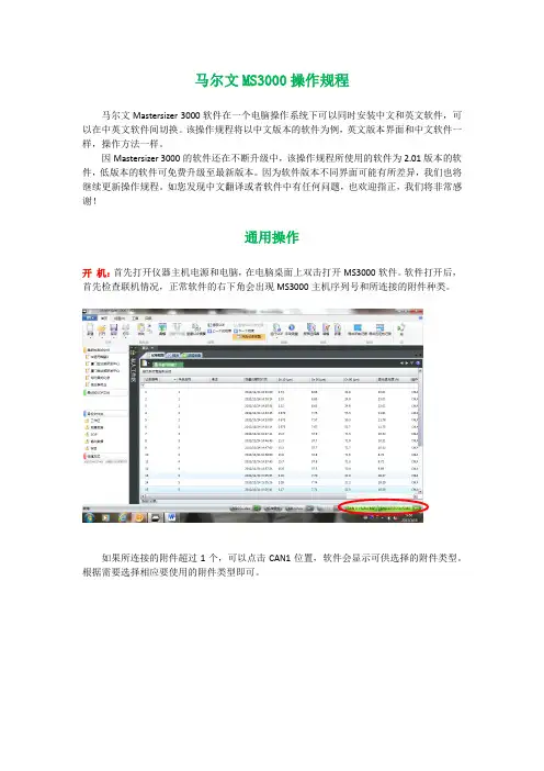
如您发现中文翻译或者软件中有任何问题,也欢迎指正,我们将非常感谢!通用操作开机:首先打开仪器主机电源和电脑,在电脑桌面上双击打开MS3000软件。
软件打开后,首先检查联机情况,正常软件的右下角会出现MS3000主机序列号和所连接的附件种类。
如果所连接的附件超过1个,可以点击CAN1位置,软件会显示可供选择的附件类型。
根据需要选择相应要使用的附件类型即可。
如果软件上不能正确显示主机和附件序列号(显示为无连接),则表示软件和MS3000仪器之间无通讯,将无法进行测试。
注:仪器主机与电脑间通过USB接口连接。
仪器附件(进样器)本身不带控制电源,电源通过MS3000主机提供。
附件通过控制电缆线接到仪器左侧的CAN接口上,一台主机可以同时连接三台附件(3个CAN接口)。
关机:当测试完成后需要关闭仪器系统时,先关闭软件,再关闭仪器电源。
关软件之前强烈建议先按一下“保存”确认再保存一下数据。
数据保存:MS3000软件默认的是数据后存储方式,即数据测试完成后用户手动按“保存”键保存数据。
为了避免忘记保存数据,也可以启动强制保存模式,即在首个菜单的下拉菜单中选择“选项”菜单,启用“强制保存记录”(前面打勾)。
这样在开始测试时,如果没有打开测试文件软件会自动进入创建测试文件的窗口。
软件界面:软件界面可以按不同方式显示,可以单一显示记录列表或者报告,也可以同时显示记录列表和分析结果界面。
通过“视图”菜单中的“默认”可以回到默认的显示方式。
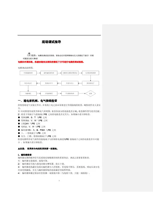
1现场调试指导电梯在外围回路、机械安装完全到位的情况下方可进行电梯的调试流程。
电梯调试流程图:一.通电前机械、电气接线检查控制系统电气安装完毕后,在系统上电之前必须要进行外围接线的检查,确保部件及人身安全。
1)应对照使用说明书和电气原理图,检查各部分的连接是否正确,2)检查下列端子与接地端子PE 之间的电阻是否无穷大,如果偏小请立即检查。
■ 变频器R 、S 、T 与PE 之间■ 变频器U 、V 、W 与PE 之间■ 主板24V 与PE 之间■ 电机U 、V 、W 与PE 之间■ 编码器15V 、A 、B 、PGM 与PE 之间■ +、-母线端子与PE 之间■ 安全、门锁、检修回路端子与PE 之间检查电梯所有电气部件的接地端子与控制柜电源进线PE 接地端子之间的电阻是否尽可能小 ,如果偏大请立即检查。
▲注意: 柜壳体与电动机壳体要一定接地。
1.编码器检查编码器反馈的脉冲信号是系统实现精准控制的重要保证,调试之前要着重检查。
1) 编码器安装稳固,接线可靠。
2) 编码器信号线与强电回路分槽布置,防止干扰。
3) 编码器连线最好直接从编码器引入控制柜,若连线不够长,需要接线,则延长部分也应该用屏蔽线,并且与编码器原线的连接最好用烙铁焊接。
4) 编码器屏蔽层要求在控制器一端接地可靠(为免除干扰,只能一端接地)。
5异步电机调谐流程图永磁同步电机调谐:1) 调谐说明a ) 永磁同步曳引机第一次运行前必须进行磁极位置辨识,否则不能正常使用。
b ) 同步机一体化控制器采用有传感器的闭环矢量控制方式,须确保F0-00 设为1(闭环矢量),且必须正确连接编码器和PG 卡,否则系统将报E20 编码器故障,导致电梯无法运行。
c ) 同步机一体化控制器既可通过操作面板控制方式在电机不带负载的情况下完成电机调谐,也可通过距离控制方式(检修方式)在电机带负载的情况下完成调谐。
d ) 调谐前必须正确设置编码器参数(F1-00、F1-12)和电机铭牌参数(F1-01、F1-02、F1-03F1-04、F1-05)。
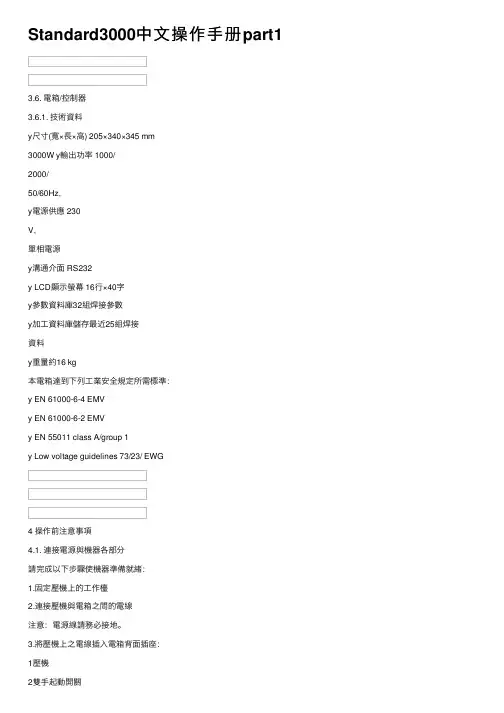
Standard3000中⽂操作⼿册part13.6. 電箱/控制器3.6.1. 技術資料y尺⼨(寬×⾧×⾼) 205×340×345 mm3000W y輸出功率 1000/2000/50/60Hz,y電源供應 230V,單相電源y溝通介⾯ RS232y LCD顯⽰螢幕 16⾏×40字y參數資料庫32組焊接參數y加⼯資料庫儲存最近25組焊接資料y重量約16 kg本電箱達到下列⼯業安全規定所需標準:y EN 61000-6-4 EMVy EN 61000-6-2 EMVy EN 55011 class A/group 1y Low voltage guidelines 73/23/ EWG4 操作前注意事項4.1. 連接電源與機器各部分請完成以下步驟使機器準備就緒:1.固定壓機上的⼯作檯2.連接壓機與電箱之間的電線注意:電源線請務必接地。
3.將壓機上之電線插⼊電箱背⾯插座:1壓機2雙⼿起動開關3RF (與換能器連接)4電源4.1.1. 主動溝通裝置5RS232插座 (9孔D-sub插座)6數位輸⼊ (25孔D-sub插座,序列埠)7數位輸出 (25孔D-sub插座,序列埠)其他資料請⾒第⼋章”資料分析”,插座配置請⾒第九章”主動溝通與信號傳送”。
4.1.2. 壓縮空氣源:最⼤7 bar;105 psi依下列指⽰轉動壓縮空氣閥(21):4.將壓縮空氣喉(21a)與壓縮空氣供應源連接。
5.將壓縮空氣閥(21)轉⾄⼯作位置。
注意:若輸⼊壓縮空氣壓⼒⼤於7 bar,附加安全氣閥會⾃動開啟釋放過多的空氣壓⼒。
4.1.3. 裝備隔⾳罩SSK-H1ADG電箱電源2數位輸⼊ (25孔D-sub插座,序列埠) 3數位輸出 (25孔D-sub插座,序列埠) 4壓機5雙⼿起動開關6RF (與換能器連接)拆除隔⾳罩後⽅⾯板可調整壓機,卸除或裝備隔⾳罩。
4.2. 操作及顯⽰元件4.2.1. 壓機1 換能器外罩內藏超⾳波發振系統及電源線。


PrefaceNoticeProduct features and specifications described in this manual are subject to change without notice.The manufacturer shall not be liable for any damage, or for the loss of information resulting from the performance or use of the information contained herein.TrademarksAccusys and the names of Accusys products and logos referenced herein are trademarks and/or service marks or registered trademarks and/or service marks of Accusys, Inc. Microsoft, Windows, Windows NT, Windows 2000, Windows 2003, Windows XP, Windows Vista and MS-DOS are either trademarks or registered trademarks of Microsoft Corporation. Intel and Pentium are registered trademarks of Intel Corporation. Mac, Mac OS, and Macintosh are either registered trademarks or trademarks of Apple. Other product and company names mentioned herein may be trademarks and/or service marks of their respective owners.All contents of this manual are copyrighted by Accusys, Inc.The information contained herein is the exclusive property of Accusys, Inc. and shall not be copied, transferred, photocopied, translated on paper, film, electronic media, or computer-readable form, or otherwise reproduced in any way, without the express written permission of Accusys Inc.Manual version 1.3© Copyright 2007 Accusys, Inc.All rights reserved.ACS-61000/61010 User’s ManualAbout this manualCongratulations on your selection of the ACS-61000/61010. The card is monitored by a Java-based RAID GUI.INTENDED USERThis manual is designed and written for users installing and using RAID GUI. The intended user should have working knowledge of RAID planning and data storage. ORGANIZATION OF THE MANUALPART ONE:IntroductionChapter 1: Introduction provides an overview of the card and its features.PART TWO:Installing the cardChapter 2: Setting up RAID GUI provides details of how to setting up your card and connecting to the RAID GUI.PART THREE: Card ConfigurationsChapter 3: Card Connections provides details of the connectors on the RAID card. PART FOUR:Card BIOS and EFIChapter 4: The Card BIOS and EFI allows the user to configure a RAID array without using the RAIDGuard X GUI.PART FIVE: AppendicesAppendix A: Specifications lists the technical details of the ACS-61000/61010 RAID card.Appendix B: Contact Us lists contact details of Accusys business units around theworld.Guide to conventionsImportant information that users should be aware of is indicated with the following icons:This icon indicates the existence of a potential hazard that could result inpersonal injury, damage to your equipment or loss of data if the safetyinstruction is not observed.This icon indicates useful tips on getting the most from your RAID card. Important terms, commands and programs are put in Boldface font.2Table of ContentsPREFACE (1)N OTICE (1)T RADEMARKS (1)A BOUT THIS MANUAL (2)INTENDED USER (2)ORGANIZATION OF THE MANUAL (2)G UIDE TO CONVENTIONS (2)TABLE OF CONTENTS (3)CHAPTER 1 - INTRODUCTION (6)O VERVIEW (6)K EY F EATURES (7)SERIAL ATA (Serial advanced technology attachment) (8)PCI-EXPRESS X 8 (8)FIRMWARE (8)BIOS and EFI (8)B EFORE YOU BEGIN (9)WHAT’S IN THE BOX (9)OPTIONAL ITEMS (10)WHAT ELSE YOU NEED (10)F AMILIARIZING YOURSELF WITH THE RAID CARD (11)OVERVIEW (11)PIN SETTINGS (12)Serial Cable Connectors (1) (12)LCD Panel Connector (2) (12)Battery Module Connector (3) (12)ACS-61000/61010 User’s Manual4 CHAPTER 2 - INSTALLATION (14)I NSTALLATION FLOWCHART (14)P RE -INSTALLATION NOTICES (15)C ARD I NSTALLATION (16)H ARD D RIVE C ONNECTION (16)LCD P ANEL (OPTIONAL ) I NSTALLATION (17)B ATTERY B ACKUP M ODULE (O PTIONAL ) I NSTALLATION (17)CHAPTER 3 - CARD CONNECTIONS (19)MINI SAS CONNECTORS (1) (20)PCI-EXPRESS X 8 CONNECTOR (2) (20)SERIAL CONNECTOR PORT (3) (20)LCD PANEL CONNECTOR (4) (20)BATTERY CONNECTOR PORT (5) (20)CHAPTER 4 - BIOS (22)QUICK ARRAY CONFIGURATION (23)CUSTOM ARRAY CONFIGURATION (24)BIOS Menu Structure (25)BIOS Menu (27)APPENDIX A - SPECIFICATIONS (29)APPENDIX B - CONTACT US (30)T AIWAN - A CCUSYS , I NC (30)A MERICA - A CCUSYS U.S.A., I NC (30)K OREA - A CCUSYS K OREA , I NC (30)C HINA B EIJING - A CCUSYS C HINA , I NC (30)E UROPE - A CCUSYS EU B.V (30)ACS-61000/61010 User’s ManualChapter 1This chapter introduces the features and capabilities ofACS-61000/61010. You will find:Ö A full introduction to your RAID cardÖ Details of key featuresÖ A checklist of package contentsÖ A checklist of what else you need to start installationÖ An overview of the RAID cardOverviewThe ACS 61000/61010 PCI Express to SATA II RAID adaptors provide the latest functionality and performance for Windows, Linux and MAC operating systems. And with a Java based GUI the RAIDGuard X server and client software offers improved functionality and manageability. Using the latest Intel XScale ® 64-bit RISC processor the eXpeRAID family of adaptors supports up to 16 x SATA I/II disk drives making it ideal for applications that require high storage capacity and fast access such as video editing, digital surveillance, file servers and shared storage.Using intelligent I/O processing and elaborate algorithms the card bypasses slow disk drives and rebuilds the data by sustaining a stable throughput and streamlining the data transfer therefore enabling the smooth handling of heavy loaded and time critical applications.Data protection is one of the key features of the eXpeRAID adaptors. Not only do they protect against disk failure but also bad sectors using online recovery and reallocation. Disk scrubbing is available to fix the bad sectors and online data and parity refresh protects against data loss caused by media aging.The RAIDGuard X management software supports the online changing of RAID configurations; quick configuration on any Java enabled platform; and with the next generation BIOS and Windows Storport driver it’s future is guaranteed.6Chapter 1 – IntroductionKey FeaturesACS-61000/61010 features the following:z Multiple RAID levels: 0,1, 0+1, 5, 6, and JBODz Up to 4 independent disk arraysz Support 4~16 x SATA I/II drivesz RAID capacity partitioning: up to 16 slicesz Support up to 64 LUNsz Variable stripe sizes, up to 256KBz Selective initialization method with on-the-fly background initialization and performance evaluationz Support over-2TB volumesz Online RAID group expansionz Online RAID level migrationz On-the-fly RAID initializationz Snapshot for fast backup and restorez Support write-back and write-through cachingz Selective and adaptive read/write optimization policiesz Fast read response by intelligently bypass slow drivez Automatic drive insertion/removal detection and fast disk rebuildingz Online bad block data recovery and reallocationz Online disk scrubbing with data refresh and parity regenerationz Disk health monitoring by S.M.A.R.T.z NVRAM-based transaction log and auto parity resynchronizationz Array roaming and drive traveling with redundant on-disk meta dataz Array recovery to restore RAID configurationsz Dual firmware images for firmware recoveryz Support boot from RAIDz Enclosure components monitoring and controlz Optimized for multiple-stream video processingz Support for Windows Mac OS and Linuxz Java-based GUI for remote managementz Reliable multi-lane SATA connectorscompliantz RoHSACS-61000/61010 User’s Manual8 SERIAL ATA (Serial advanced technology attachment)The ACS-61000/61010 is designed for use with the latest Serial ATA II hard disk drives. Serial ATA (often abbreviated as SATA or S-ATA) allows data transfer up to 3 Gbps and is compatible with older Parallel ATA standards. It has an additional advantage parallel ATA in that cables are thinner, so airflow within computer cases is less impeded, and can extend to one meter in length (against only 40 cm for parallel ATA).PCI-EXPRESS X 8Developed by Intel in 2002 PCI-Express has been developed to match the speed of CPUs. It provides a serial communications channel that provides up to 2.5 Gbits/sec in each direction of a pair of wires. The 8 refers to the number of pairs of wires, therefore allowing a maximum of 20 Gbits/sec transfer.FIRMWAREAppropriate firmware must be loaded into the card for it to function. ACS-61000/61010 and are shipped with firmware preloaded. Check the installation disk that came with the package to find a backup firmware copy. You can also periodically check the vendor’s web site to find the latest firmware version for use with the card.BIOS and EFIThe ACS-61000/61010 contains an internal BIOS and EFI which can be used to configure a RAID Array instead of using the RAIDGuard X GUI. The BIOS and EFI are accessed as the card boots up and contains all the functionality of the RAIDGuard X GUI. The BIOS and EFI may be upgraded using the RAIDGuard X GUI, see for upgrades.Chapter 1 – IntroductionBefore you beginWHAT’S IN THE BOXSome vendors may ship certain components as standard, while other vendors treat the same component as optional. In its most basic configuration, your package should include the following:z 1 x ACS-61000/61010 PCI-Express toSATA RAID Cardz1~4 x Mini SAS x 4 multi-lane cable(50cm) by different modelz Quick Start Guidez Installation CD (includes ApplicationSoftware and Hardware user manuals)ACS-61000/61010 User’s Manual OPTIONAL ITEMSz Battery Backup Module (BBM) –theBBM stores the cached data in the eventof power supply failure.z LCD Control panel for seeing card statusand advanced configuration.WHAT ELSE YOU NEEDz LBA 48 bit Hard disk drives (HDDs) (different RAID levels requires different numbers of HDDs. See the RAIDGuard X User Manual to determine how many HDDs you require).z Disk enclosure / disk storage locations and power connection for each disk drive. z Host computer with spare PCI-e slot.z Static grounding strap or electrostatic discharge (ESD) safe work area.The hard drives in a RAID should match in size and speed. All drives in anyarray should be identical models with the same firmware versions. Arrayscan use a minimum of 1GB HDDs, however, the smallest drive will determinethe size of the array.The PCI-e slot on some motherboards is for graphics cards only. Check withthe motherboards vendor for compatibility.10Chapter 1 – IntroductionFamiliarizing yourself with the RAID card OVERVIEW1. Mini SAS connectors2. PCI-Express x 8 connector3. Serial cable connector4. LCD panel connector5. Battery module connector6. DDR memory connectorACS-61000/61010 User’s ManualPIN SETTINGSThe PIN settings on the card are as follows:Serial Cable Connectors (1)Connect the red strip of the serial connector cable to pin 1.LCD Panel Connector (2)Battery Module Connector (3)11012ACS-61000/61010 User’s ManualChapter 2This chapter presents:Ö Instructions on installing the card in the host system. Ö Instructions on installing hard drives.Installation flowchartInstallation of ACS-61000/61010 is simple. This chapter will lead you though the steps:14 zInstall the card in a host system.z Connect a Mini SAS cable from each hard disk drive in the intended array to one of the connectors on the card. zConnect power cables to each of the hard drives.zHardware installation complete.This manual provides full installation and setup instructions for the ACS-61000/61010 RAID card.Chapter 2 – InstallationPre-installation noticesBefore starting any kind of hardware installation, please ensure that allpower switches have been turned off and all power cords disconnected toprevent personal injury and damage to the hardware.To avoid overheating, ACS-61000/61010 should be installed in a well-ventilated area and in such a way that sufficient airflow is maintained acrossthe card chips.candamage electronic components. To guard against suchelectricityStaticdamage:Work in a static-free environmentWear a grounded anti-static wrist strapStore uninstalled components in anti-static bagsHandle PCBs by their edges and avoid touching chips and connectors.Environmental requirementsOperating Temperature: 0°C to 50°C (32°F to 122°F)Storage Temperature: -20°C to 70°C (-4°F to 158°F)Operating Humidity: 5-85%, non-condensingStorage Humidity:5-95%, non-condensingACS-61000/61010 User’s Manual Card InstallationRead the pre-installation notices earlier in this chapter before proceeding. 1. Remove the blanking plate from thePCI-e slot.2. Position the connector of the card overthe expansion slot.3. Press the connector of the card gentlybut firmly into the expansion slot until itis correctly and securely seated.4. Secure the metal bracket of the card tothe system case with a screw.5. Go to the Hard drive connection.Many mother boards only come with 1 PCI-Express interface, beforeinstallation ensure there is one free.Hard Drive Connection1. Attach Mini SAS cables to theconnectors on the card. One cable cancontrol a maximum of 4 HDDs.2. Install the disks in the desired locationeg within the system case or within anindependent disk rack.3. Connect the other end of each cable tothe connectors on each of the harddrives.4. Attach a power connector to each drive,either from the host system or from anindependent power source.16Chapter 2 – InstallationLCD Panel (optional ) InstallationRead the pre-installation notices earlier in this chapter before proceeding. 1. Remove or open the system case toallow access to the 51/4” drive bay youare going to use for the LCD panel.2. Remove the blanking plate from thisslot.3. With the cables connected to the backof the LCD panel, slide the panel intothe system case.4. Secure the LCD panel using screws oneither side.5. Connect the cables to the card.6. Go to the Card Installation.Battery Backup Module (Optional) Installation1. Open the case of the host computerand remove a blanking plate from therear.2. Connect the cables of the BBM to the61000/61010 card, as shown.3. Secure the BBM to the space left by theblanking plate.4. Close the case.The BBM is approximately 2cm high; ensure that your computer case hassufficient room.ACS-61000/61010 User’s Manual18Chapter 3 – Card ConnectionsChapter 3This chapter details the usage of the connectors on theACS-61000/61010 cards.In addition to the ports used for connecting to HDDs; the ACS-61000/61010 also includes connectors for external devices.1. Mini SAS connectors2. PCI-Express x 8 connector3. Serial cable connector4. LCD panel connector5. Battery backup module connector6. DDR memory connectorACS-61000/61010 User’s ManualMINI SAS CONNECTORS (1)Used for connecting the interface cables to Hard Disk Drives. See Part 2 Hard Drive Connection.PCI-EXPRESS X 8 CONNECTOR (2)Used for connecting the card into the server. See Part 2 Card Installation.SERIAL CONNECTOR PORT (3)The serial connectors (2 supplied) allow engineers to configure the card from a terminal connection. Since this requires specialized knowledge it is recommended that the included GUI is used.LCD PANEL CONNECTOR (4)The LCD Panel and connector (not supplied) enable you to configure the card without using the BIOS or RAIDGuard X GUI.Follow the instructions below to use the LCD panel:1. Use the up and down buttons to cycle through the menus.2. Press the ENT button to access the menus and confirm a command.3. Press the ESC button to return to the previous menu.BATTERY CONNECTOR PORT (5)The battery connector port is used to attach a ACS-1161 or ACS-1162 battery backup module (optional). In the event of the PSU failing on the server during saving and transmission of data the module will keep the data in the cache memory until the card resume its work. The BBM occupies 1 rear blanking slot and once charged the BBM will last for more than 72 hours (on board memory).20ACS-61000/61010 User’s Manual Chapter 4This chapter details the usage of the BIOS on the ACS-61000/61010.The BIOS functionality is similar to that of the RAIDGUARD X application. Below is a menu tree detailing the menu structure of the BIOS.1. Start the server and watch the screen. When it gets to the position shown below pressEnter.2. Enter the password (the default is 00000000 (8 zeros) and press Enter.22Chapter 4 – BIOSQUICK ARRAY CONFIGURATION1. For first time use go RAID Configuration > Create Array > Quick Array Configuration.The BIOS will recognize how many drives are installed and provide the best solution.Type Y to begin configuration.1. If there are only 2 disks installed the default RAID array is 0 (zero).2. If there are more than 2 disks the default RAID array is 5.ACS-61000/61010 User’s ManualCUSTOM ARRAY CONFIGURATION1. To change the details of an Array go to RAID Configuration > Create Array > CustomArray Configuration. See the screen below for configuration details.2. Use the Tab button to switch between windows.All other features are accessible through the RAIDGuard X application supplied with the card. See the supplied manual for details on how to use these functions.24Chapter 4 – BIOSBIOS Menu StructureThe BIOS menu structure details how the commands in the BIOS relate to each other. The BIOS manages the same information as the RAIDGuard X application, see it's user manual for further details on these functions.ACS-61000/61010 User’s Manual26Chapter 4 – BIOSBIOS MenuThe menu below gives brief information about the functions of the BIOS menu, for further details see the RAIDGuard X user manual.RAID ConfigCreate Array Quickly create and array, administer the details ofa current and array and configure a JBODSet Slice Add and delete slicesLUN and Map Display details and sets LUNs and Maps Locked Disk Unlock locked disksRefresh Array Refresh an array to improve performanceRAID Checking Check that the RAID is functioning correctly RAID Expansion Expand the disks of an arrayRAID Migration Migrate an array from one RAID type to anothereg from RAID 5 to RAID 1Disk Config UtilityAutomatic Detection Detects installed disksDisk Information Displays manufacturer and speed details of theinstalled disksController Config UtilityPassword Change Change the BIOS passwordSerial Number Display the serial number of the RAID card System Cache Activate and disable the system cacheDisk Cache Activate and disable disk cachingDisk Lag Proof Activate and disable disk lag proof modeNCQ Mode Activate and disable NCQ modeSynchronize Cache Mode Activate and disable synchronize cache mode Real Time Clock Display and set the BIOS clockS.M.A.R.T. Activate and disable S.M.A.R.T. warnings andpolling frequencyMax pre-fetch number Set the maximum number of stripes that can bepre-fetched by the arrayAbout Displays the BIOS version and companyinformationExit Exits the BIOSACS-61000/61010 User’s Manual28Appendix A – SpecificationsAppendix ACPU Intel 80333PCI Express One PCI-e x 8PCI64-bit PCIX-133R6 support YesDiskDisk Interface SATA II/SATADisk Channel 4~16 HDDs, 1~4 internal mini SAS connector Disk Interface Chip Marvell 6081 x 1~2HostHost Channel PCI-e x 4 or x 8 lane from PC.Memory (ACS-61000)Memory type On board DDR 2 memory chipMemory size 256MB with 64-bit DDR II 400 with ECC Memory (ACS-61010)Memory type DDR SODIMMMemory size 64MB ~ 2 GB (with or without ECC)SDRAM type 128/256/512 Mbit and 1Gbit chip densityUser Interface (option)LCD Interface One LCD panel - 2 lines by 16 characters, oneconnector on HBA card.Button Interface UP, Down, ESC, Enter, one connector on HBAcardYes, one on-board connector supportBattery backup interface(option)Fan support Yes, 1 fan connector, support +12V fan Terminal Port For users messages, out-band APIDisk status LED For disk fail and access LEDConnector Two 2x8 pin connector without housing Dimensions Board size 187.7mm(L) x 68.9mm(H)PCB thickness 1.6 mmOperating parametersOperating Temperature 0°C ~50°COperating Humidity 5%~85%, Non-condensingStorage Humidity 5%~95%Storage Temperature -20°C ~70°CACS-61000/61010 User’s Manual30 Appendix BTaiwan - Accusys, Inc.• 5F.,No.38, Taiyuan St., Jhubei City, Hsinchu County 302, Taiwan, R.O.C. • Tel : +886-3-560-0288 • Fax : +886-3-560-0299• / • e-mail:*****************.twAmerica - Accusys U.S.A., Inc.• 46710 Fremont Blvd. Fremont, CA 94538, U.S.A. • Tel :+1-510-661-0800 • FAX :+1-510-661-9800 • Toll-free number:+1-866-277-5888 • /• e-mail:**********************,********************Korea - Accusys Korea, Inc.• Baegang B/D 5F Shinsa-Dong 666-14 Kangnam-Gu, Seoul, Korea • Tel : (02)6245-9050 • Fax : (02)3443-9050• http://www.accusys.co.kr/ • e-mail:****************.krChina Beijing- Accusys China, Inc.• B1701, Horizon International Tower, No.6, ZhiChun Road, HaiDian District, Beijing • Tel: +86-10-82800080 • Fax: +86-10-82800784 • E-mail: *****************.cn • Europe - Accusys EU B.V• Columbusstraat 2-10, 3165 AD Rotterdam, Netherlands • Tel : +31-10-4284117 • Fax : +31-10-4284114• • ftp://• e-mail:*******************,*********************。
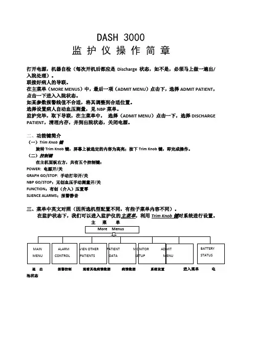
DASH 3000监护仪操作简章打开电源,机器自检(每次开机后都应是Discharge状态,如不是,必须马上做一遍出/入院处理)。
联接好病人的导联。
在主菜单(MORE MENUS)中,最后一项(ADMIT MENU)点击下,选择ADMIT PATIENT,点击一下进入入院状态。
如某参数报警线值不合适,将其调整到合适位置。
选择设置病人自动血压测量,见NBP菜单。
监护完毕,取下导联,在主菜单中,选择(ADMIT MENU)点击一下,选择DISCHARGE PATIENT,清理内存,并到出院状态,关闭电源。
二、功能键简介(一)Trim Knob键旋转Trim Knob键,屏幕上被选定的内容为高亮;按下Trim Knob键,即完成操作。
(二)控制键在主机面板右方,共有五个控制键:POWER: 电源开/关GRAPH GO/STOP: 手动打印开/关NBP GO/STOP:无创血压手动测量开/关FUNCTION:有创(介入)压置零SLIENCE ALARMS:报警静音三、菜单中英文对照(因所选机型配置不同,有些子菜单内容不同)。
在监护状态下,我们可以进入监护仪的主菜单,利用Trim Knob键对系统进行设置。
主菜单退出报警控制观看其他病情数据病情数据系统设置进入菜单电池状态A) ALARM CONTROL的子菜单为:• ALL LIMI TS:所有报警界限• ARRHYTHMIA ALHRM LEVEL:心律失常报警界级别• PARAMETER ALARM LEVEL:参数报警级别• ALARM HELP:报警帮助/模拟• DISPLAY OFF ALARM PAUSE:关闭显示,暂停报警• ALARM VOL:报警音量• CLEAR ALAMS:清除报警• ALARM HISTORY:报警事件回顾B) VIEW OTHER PATIENTS在连网中,可以观察别的床位病情资料• VIEW ON ALARM OPTIONS:查看报警开/关•GRAPH VIEWED BED:打印查看的床位•SELECT A BED TO VIEW:选看网络中其他床位• SELECT ANOTHER CARE UNIT:选择网络中其它科室PATIENT DATA的子菜单为:• ALARM HISTORY :报警历史• VITAL SIGNS:生命体征回顾• GRAPHIC T RENDS:趋势图• CARDIAC CALCS:心功指数计算• PULMCNARY CALCS:肺功指数计算• DOSE CALCS :药物计量计算• LAB DATA:由此进入医院实验室数据信息管理系统(LIS),查看病人相关实验室数据。

CMG3000操作手册目录1、安全2、部件及安装2.1 CMG3000介绍2.2 安装3、PRIME/充填模式4、INJECTION/注塑模式4.1 选择注塑模式4.2 在AUTO CAL 模式下设定工艺参数4.3 信号完整性及计时器功能的问题4.4 在非AUTO CAL 模式下设定工艺参数5、EXTRUSION/挤出模式5.1 选择挤出模式5.2在AUTO CAL 模式下设定工艺参数5.3 TRACK功能5.4在非AUTO CAL 模式下设定工艺参数6、报警器7、故障排除8、维修及服务1、安全安全起见,操作本设备人员必须有资质并接受过相关培训,在操作前详细阅读并理解本手册内容,认识到其中的危险。
安装和维护本设备的人员必须有资质能胜任本工作。
警告:请勿擅自拆卸本设备。
有电,危险!有触电及着火危险。
在维护之前请切断电源。
2、部件及安装2.1 CMG3000介绍图1.1 CMG3000背面图,包括以下部件a. 配有开关和保险的电源插孔。
更换保险丝的操作详见4。
b. 四孔(配有地线)信号插孔。
详见1.3。
c. 报警器。
与可选的液面感应器配合使用。
d. 设备编码标牌e. 电压选择开关f. 小车连接接口g. 外部连接接口h. 数据输出接口图1.1 CMG3000 背面图图1.2为CMG3000侧视图。
标识为马达连接接口图1.2 CMG3000侧面面板图1.3为CMG3000正面面板,包括以下部分1. 六位数字显示器2. 固定LED显示。
如果“PUMP”亮,表示泵在运转;如果“SINGNAL”亮,表示有信号输入。
3. 马达控制按钮“FORWARD/正向转动”和“STOP/停止”。
用来运转马达或停止。
4. 数据输入按钮。
一组箭头用来调整一位数字。
5. 模式按键和LED显示。
用来选择将要运行系统的模式。
三个模式按键“PRIME/充填”,“INJECTION/注塑”和“EXTRUSION/挤出”。
“AUTO CAL/自动计算”功能会和挤出或注塑模式配合使用。
6.關上外罩(7)收緊螺絲(8)再上好換能器並將之用扳手收緊。
7.再打開外罩(7),取出增幅器(25)及換能器(24),再調轉過來。
8.插上RF插頭(23),換能器向上,將起振系統掛回外罩內。
9.關上外罩,再上好焊頭並用扳手收緊。
5.3.3. 調校焊頭高度1.估計操作者方便置入及取出工件的高度H。
1焊頭2工件3底模4工作檯2.鬆開止付螺絲(6.1),旋轉下壓距離微調螺絲(6),檢視下壓距離刻度尺(18)來調整合適的焊頭下壓距離(H)。
3.設定完畢再鎖上止付螺絲固定下壓距離。
4.鬆開機身上下鎖掣(19),以高低調校手輪(20)調整合適的機身高度,使焊頭下壓時不至於壓碎工件。
5.調整好適當高度後,再將上下鎖掣鎖緊。
注意:假若焊頭升得不夠高的話,會有壓碎工件的危險。
5.3.4. 連接氣壓源1.確認緊急停止掣已拉起(解除鎖定)。
2.打開壓縮空氣閥。
注意:不可觸摸焊頭。
3.按下電箱之POWER鍵開啟機器,此時會執行自我測試。
輸入PIN碼後進入”Adjustment”選單建議設定值緩衝模式:3系統空氣壓力:3 bar注意:此時不可將裝載工件的底模置於焊頭下方。
4.按下雙手起動按鈕使焊頭下壓。
5.將裝載工件的底模放置於焊頭下方,對準中央。
6.緩慢轉動調校手輪使促動器下壓至焊頭觸及底模上的工件為止。
7.鎖緊機身上下鎖掣。
8.鎖緊六角螺絲。
9.先稍微固定兩邊,查看底模是否有確實固定在中央,再將螺絲鎖緊。
10.按下雙手起動按鈕使焊頭上行至原始位置。
11.取出焊接工件。
12.再次按下雙手起動按鈕使焊頭下壓。
13.鬆開機身上下鎖掣使促動器下壓至最低點,確認焊頭未接觸底模。
此步驟可確保底模未裝載工件時,焊頭下壓過低而接觸底模造成焊頭與底模損壞。
14.進入主選單之”Database / Parameterdatabase”項目,選擇需要的參數設定後,按下F1鍵”Load data set”,即可載入資料設定組合。
15.按下PARAMETER鍵確認所選擇的參數設定符合焊接要求。
[分类:受限制]Check Point版权声明©2020Check Point Software Technologies Ltd.保留所有权利。
本产品及相关文档受版权保护,并且凭限制其使用、复制、分发及反编译的许可进行分销。
未经Check Point的事先书面授权,不得对本产品或相关文档的任何部分,以任何形式或任何方式进行复制。
在本手册编制过程中已非常谨慎,但Check Point不对任何错误或疏漏承担责任。
本出版物及其中所述功能如有更改,恕不另行通知。
限制权利图注:政府的使用、复制或纰漏须符合DFARS252.227-7013和FAR52.227-19的“技术数据和计算机软件权利”一条中第(c)(1)(ii)款规定的限制。
商标:参考版权页以获取我们的商标清单。
参考第三方版权声明以获取相关版权和第三方许可的清单。
重要信息最新软件我们建议您安装最新版软件,以获得最新的完善功能、更好的稳定性、更高的安全级别,并防止发展中的新攻击入侵。
认证有关Check Point产品的第三方独立认证,请参见Check Point认证页面。
Check Point3000设备如需更多有关此版本的信息,请参见主页。
此文档的最新版本请打开网页浏览器中此文档的最新版本。
请下载此文档(PDF格式)的最新版本。
反馈Check Point一直在致力于完善其文档。
请发送您的意见给我们,以帮助我们不断改进。
修订历史目录安全和环保声明7合规信息9符合性声明9引言14欢迎14 3000设备概述14装运箱内容物15术语15将3000设备安装于机架16设备物理规格16设备通风口16配置3000设备18启动设备18可用软件映像18初始配置18创建网络对象18高级配置18连接至3000设备CLI19 3000设备硬件20前面板20后面板22在3100/3200设备中安装电源配适器固定夹22双冗余BIOS25更换和升级组件26恢复出厂默认设置27通过Gaia门户进行恢复27通过启动菜单恢复27通过Gaia Clish进行恢复28注册和支持29注册29支持29如何进阶?29安全和环保声明请在设置或使用设备前阅读以下警告。
M3000电梯控制系统调试手册GWH2012.1.82233345678-111112-131415附件2、轿顶插件箱插件目录————————————————————————————————————————————————————————————————————————————————————1、主控制板示意图2、主控制板指示灯说明3、主控制板输入信号端子功能说明4、主控制板输出端子功能说明5、主控制板编码器安装说明6、主控制板小键盘的功能及使用说明7、轿顶控制板说明8、操纵箱指令板说明9、楼层显示板说明10、功能参数说明11、故障代码表12、主机自调谐说明附件1、控制柜插件标号EROKCOPHOPMODBUSX1—X24Y1—Y6名称故障指示灯正常指示灯轿顶板通讯指示灯召唤通讯指示灯并联指示灯输入指示灯输出指示灯说明系统检测到故障时,报警同时ER指示灯亮(红色)系统正常无故障时亮(绿色)系统主板MCB与操纵箱板CTB通讯正常时闪烁(绿色)系统主板MCB与召唤板HCB通讯正常时闪烁(绿色)系统处于并联通讯正常时闪烁(绿色)输入信号有效时(信号接通)亮(绿色)系统输出时亮(绿色)2、主控制板指示灯说明1、主控制板示意图端口号状态X1常开X2X3常闭X4常闭X5常闭X6常闭X7常闭X8常闭X9常闭X10常闭X11常闭X12常开X13常开X14常开X15常开X16常闭X17常开X18常开X19常闭X20常闭X21常开X22常闭X23常开X24常开端口号端口号Y1Y4M1M4Y2Y5M2M5Y3Y6M3M6端口号端口号12VPGMPGAPGBPGMPE标号D8D11 同步曳引机时,系统选用海德汉ERN1387型SIN/COS编码器,必须安装PG卡(MCTC-PG-E),PG卡端口CN1直接连接编码器。
说明B+/B-差分信号指示灯,运行中闪烁;A+/A-差分信号指示灯,运行中闪烁;功能说明提供DC12V编码器电源,适用于增量型推挽输出或增量型集电极开路输出两种方式的编码器;编码器脉冲信号A输入编码器脉冲信号B输入电源0V端子连接编码器屏蔽层5.2、同步编码器安装说明同步封星接触器控制(同步时使用)COM(Y5)停电应急运行自动切换COM(Y6)5、主控制板编码器安装说明5.1、异步编码器端子说明CN6COM(Y1)功能说明并联时使用COM(Y4)检修信号自动时,灯亮;检修时,灯灭;检修上行信号检修下行信号封星接触器检测信号接触器吸合,灯亮;接触器断开,灯灭;(同步时使用)安全接触器检测信号4、主控制板输出端子功能说明接触器吸合,灯亮;接触器断开,灯灭;运行接触器信号运行时,灯灭;停止时,灯亮;轿门门锁接触器检测信号接触器吸合,灯亮;接触器断开,灯灭;厅门门锁接触器检测信号接触器吸合,灯亮;接触器断开,灯灭;制动接触器信号运行时,灯灭;停止时,灯亮;机房超载信号正常时,灯亮;超载时,灯灭;(超载在机房时使用)停电检测信号输入消防联动信号(选用)正常时,灯灭;满载时,灯亮;(满载在机房时使用)备注:输入信号(X1——X24)的公共端为DC24V(+)备注:输入信号(X1——X24)的公共端为DC24V(+)功能说明运行接触器控制说明在门区时,灯亮;未在门区时,灯灭;开关未动作时,灯亮;动作时,灯灭;开关未动作时,灯亮;动作时,灯灭;门区信号输入备用上行限位信号功能说明下强换信号输入3(>2.0m/s)开关未动作时,灯亮;动作时,灯灭;制动接触器控制COM(Y2)消防联动输出COM(Y3)上强换信号输入1(≤1.5m/s)开关未动作时,灯亮;动作时,灯灭;上强换信号输入2(≤2.0m/s)开关未动作时,灯亮;动作时,灯灭;上强换信号输入3(>2.0m/s)开关未动作时,灯亮;动作时,灯灭;下行限位信号开关未动作时,灯亮;动作时,灯灭;下强换信号输入1(≤1.5m/s)开关未动作时,灯亮;动作时,灯灭;下强换信号输入2(≤2.0m/s)制动器开关信号运行时,灯灭;停止时,灯亮;机房满载信号6.1、小键盘按键功能说明6.2、小键盘显示菜单分类6.3、小键盘各菜单功能详述如下00-无功能;01-封锁外召;02-封锁开门;03-封锁超载;04-封锁限位开关。
CMG3000操作手册目录1、安全2、部件及安装2.1 CMG3000介绍2.2 安装3、PRIME/充填模式4、INJECTION/注塑模式4.1 选择注塑模式4.2 在AUTO CAL 模式下设定工艺参数4.3 信号完整性及计时器功能的问题4.4 在非AUTO CAL 模式下设定工艺参数5、EXTRUSION/挤出模式5.1 选择挤出模式5.2在AUTO CAL 模式下设定工艺参数5.3 TRACK功能5.4在非AUTO CAL 模式下设定工艺参数6、报警器7、故障排除8、维修及服务1、安全安全起见,操作本设备人员必须有资质并接受过相关培训,在操作前详细阅读并理解本手册内容,认识到其中的危险。
安装和维护本设备的人员必须有资质能胜任本工作。
警告:请勿擅自拆卸本设备。
有电,危险!有触电及着火危险。
在维护之前请切断电源。
2、部件及安装2.1 CMG3000介绍图1.1 CMG3000背面图,包括以下部件a. 配有开关和保险的电源插孔。
更换保险丝的操作详见4。
b. 四孔(配有地线)信号插孔。
详见1.3。
c. 报警器。
与可选的液面感应器配合使用。
d. 设备编码标牌e. 电压选择开关f. 小车连接接口g. 外部连接接口h. 数据输出接口图1.1 CMG3000 背面图图1.2为CMG3000侧视图。
标识为马达连接接口图1.2 CMG3000侧面面板图1.3为CMG3000正面面板,包括以下部分1. 六位数字显示器2. 固定LED显示。
如果“PUMP”亮,表示泵在运转;如果“SINGNAL”亮,表示有信号输入。
3. 马达控制按钮“FORWARD/正向转动”和“STOP/停止”。
用来运转马达或停止。
4. 数据输入按钮。
一组箭头用来调整一位数字。
5. 模式按键和LED显示。
用来选择将要运行系统的模式。
三个模式按键“PRIME/充填”,“INJECTION/注塑”和“EXTRUSION/挤出”。
“AUTO CAL/自动计算”功能会和挤出或注塑模式配合使用。
MACAS3000门禁管理系统Macas3000 Management System操作员手册Operating Instructions适用于V1.0版本录MD3-S0784-0910-V1.7 版权所有,翻印必究 ! 安装、调试、操作之前,请仔细,阅读资料。
否则,因操作不当引起设备或系统损坏,责任自负!更改记录目录1安装配置 (5)1.1门禁监视终端(A CCESS M ONITOR) (5)1.1.1安装 (5)1.1.2配置 (5)1.2刷卡显像终端(E NTRY D ISPLAY) (6)1.3巡更系统 (7)1.3.1巡更服务程序(TourServer ) (7)1.3.1.1安装 (7)1.3.1.2配置 (7)1.3.2巡更终端(Tourmonitor) (7)1.3.2.1巡更程序导入服务(TourImporter) (8)1.4液晶读卡器配置软件(READERCONFIGURA TOR) (8)1.5键盘密码重置器(P ASSWORD R ESETTER) (9)2卸载 (9)3功能介绍 (10)3.1门禁监视终端(A CCESS M ONITOR) (10)3.1.1登录 (10)3.1.2初始化设置 (10)3.1.3菜单 (10)3.1.4文件菜单 (10)3.1.5地图菜单 (10)3.1.6高级菜单 (11)3.1.6.1参数设置 (11)3.1.6.2视频设置 (13)3.1.6.3所有门动作 (13)3.1.6.4事件查询 (13)3.1.6.5事件过滤设置 (14)3.1.7便捷任务管理 (14)3.1.8其他菜单 (15)3.1.9帮助菜单 (16)3.1.10新建、编辑、删除地图 (17)3.1.10.1新建地图 (17)3.1.10.2删除地图 (19)3.1.11设备控制板 (19)3.1.11.1门禁机动作 (19)3.1.11.2报警点动作 (19)3.1.11.3继电器动作 (20)3.1.11.4布防和报警状态 (20)3.1.11.5辅助输入输出状态 (20)3.1.12设备信息 (21)3.1.13图标信息 (21)3.2巡更终端(T OURMONITOR) (22)3.3刷卡显像终端(E NTRY D ISPLAY) (22)3.3.1配置系统参数 (22)3.3.2配置显像设备 (22)3.3.3配置显像模板 (23)3.4液晶读卡器配置器 (27)3.5键盘密码重置器(P ASSWORD R ESETTER) (28)3.6巡更终端(T OURMONITOR) (29)3.7安装T OUR M ONITOR I NSTALL.EXE (29)3.8登录 (31)3.9菜单 (32)3.9.1文件菜单 (32)3.9.2线路信息菜单 (32)3.9.3高级 (33)1安装配置1.1门禁监视终端(AccessMonitor)1.1.1安装✓门禁监视终端是门吉利Macas3000综合保安系统的必需客户端工作站,安装程序集成在Macas3000的安装包中。
✓将Macas3000的安装盘放入光驱并浏览,我们可以看到类似图(3.1-1)所示的内容:图(1.1-1)◆首先,安装工作环境●双击macas3000的安装程序,在【工作环境安装】中选择“安装MYSQL数据库服务器”、“微软.NET运行环境”;●如果与服务器安装在同一台计算机中,还需要安装“JDK java运行环境”;●具体的安装介绍请参阅管理员手册相关内容。
◆其次,安装一卡通数据库●如果监视终端独立安装在某台计算机中,当安装程序运行到“安装一卡通数据库”时选择[不安装(跳过)]。
●具体的安装介绍请参阅管理员手册相关内容。
◆再次,安装服务器部分●如果监视终端独立安装在某台计算机中,当安装程序运行到“安装服务器部分”时不选择任何一个服务器并点击[下一步]进入到客户端部分的安装选择界面。
●具体的安装介绍请参阅管理员手册相关内容。
◆最后,安装门禁监视终端●在客户端部分将“门禁监视终端”选中并点[下一步]安装监视终端;●门禁系统对客户端工作站的安装目录没有特殊要求,用户可以选择默认路径“D:\ProgramFiles\Melucky”也可以自定义安装路径;●如果只是安装客户端工作站,那么,安装程序安装完客户端进入到“WEB服务器配置”部分时,可以选择[跳过本页]结束安装操作。
1.1.2配置✓在macas3000的WEB管理系统中给监视终端授权并增加合法的监视员。
✓登录macas3000的WEB管理页面,在【基本设置部分】选择【服务站部分】的【监视终端设置】中增加监视终端并指定归属于哪个服务PC(本地管理系统),填写内容如下图:图(1.1-2)✓在【系统用户管理】的【监视操作员管理】中增加监视操作员并授权:图(1.1-3)✓权限包括:修改地图的权限、操作设备的权限、可监视的服务PC的范围等。
1.2刷卡显像终端(EntryDisplay)✓特殊订制产品,有独立的安装程序。
✓双击刷卡显像安装程序,进入到安装首页,请仔细阅读协议内容并做选择:选择【下一步】继续安装操作,选择【取消】退出安装程序。
✓与监视终端类似,用户可以自定义安装路径,也可以按默认路径安装;✓若安装正确,程序结束时自动出现安装完毕提示窗口,用户点【完成】结束安装。
图(1.2-1)1.3巡更系统◆特殊订制产品,有独立的安装程序。
◆包括:巡更服务程序(TourServer)、巡更监视终端(Tourmonitor)、巡更程序导入服务(TourImporter)等;1.3.1巡更服务程序(TourServer )1.3.1.1安装◆双击刷卡显像安装程序,进入到安装首页,请仔细阅读协议内容并做选择:选择【下一步】继续安装操作,选择【取消】退出安装程序。
◆与监视终端类似,用户按默认路径“D:\usr\local\melucky\macas3000LC”安装;◆若安装正确,程序结束时自动出现安装完毕的提示窗口,用户点【完成】结束安装。
1.3.1.2配置◆为了在启动本地服务的同时可以启动巡更服务程序,需要配置位于D:\usr\local\melucky\macas3000LC\startMACAS3000LC.bat文件;图(1.3-1)◆增加图中红色方框中的语句并保存,重新启动巡更服务程序即可。
1.3.2巡更终端(Tourmonitor)◆双击刷卡显像安装程序,进入到安装首页,请仔细阅读协议内容并做选择:选择【下一步】继续安装操作,选择【取消】退出安装程序。
◆与监视终端类似,用户可以自定义安装路径,也可以按默认路径安装;◆若安装正确,程序结束时自动出现安装完毕的提示窗口,用户点【完成】结束安装。
◆登录巡更终端需要合法身份:在aclocalmanager(本地服务管理的WEB页面)的【系统用户管理】---【巡更监视员管理】中增加合法的监视员信息1.3.2.1巡更程序导入服务(TourImporter)◆巡更导入程序服务的目的是把第三方巡更设备的原始巡更数据导入到门吉利一卡通数据库中,以备门吉利巡更系统统计管理;适用于使用第三方巡更设备的用户。
◆安装过程请参考巡更服务程序的安装介绍;◆安装程序为;◆请用户务必安装于本地服务系统macas3000lc路径下,默认路径为D:\usr\local\ melucky\macas3000LC\TourImporter;◆请在有关人员的指导下配置相关的配置文件tourimporter.properties(默认的安装路径为D:\usr\local\melucky\macas3000LC\TourImporter\conf:图(1.3-2)1.4液晶读卡器配置软件(readerconfigurator)✓特殊订制产品,专为macas3000系统中使用的液晶读卡器的配置软件有独立的安装程序。
✓安装过程与门禁监视终端类似,安装程序为ReaderConfigurator Install.EXE;✓双击进入到协议界面,请仔细阅读协议内容,同意安装请点击“下一步”,进入到安装目录的设置界面;✓液晶读卡器的配置软件是独立的硬件设备参数设置的工具软件,没有安装路径的限制,用户可自行设置;✓指定安装路径后可以按安装程序的引导安装,直至出现安装成功的确定提示窗口(如下图)时点击“完成”结束安装。
图(1.4-1)1.5键盘密码重置器(PasswordResetter)✓特殊订制产品,专为初始化macas3000系统中使用的密码键盘控制器的密码的配置软件;✓有独立的安装程序。
✓安装过程与门禁监视终端类似,安装程序为PasswordResetterInstall.EXE;✓双击进入到协议界面,请仔细阅读协议内容,同意安装请点击“下一步”,进入到安装目录的设置界面;✓密码键盘控制器的重置软件是独立的初始化硬件备参数的工具软件,没有安装路径的限制,用户可自行设置;✓指定安装路径后可以按安装程序的引导安装,直至出现安装成功的确定提示窗口(类似于图1.4-1)时点击“完成”结束安装。
2卸载✓直接删除各个终端的安装目录下的对应文件夹即可,如卸载门禁监视终端,直接删除“D:\Program Files\Melucky\AccessMonitor”✓删除计算机操作系统的桌面上的快捷图标如“MACAS3000门吉利门禁监视终端”:✓删除开始菜单相关条目,如卸载门禁监视终端,选择“开始”菜单中“本地管理系统”下的“门吉利门禁监视终端”的右键菜单中的“删除”并执行即可。
图(1.6-1)3功能介绍3.1门禁监视终端(AccessMonitor)✓门禁监视(AccessMonitor)负责实时反馈各个门禁设备的运行状态、故障及时告警、手动操作门禁设备的设防、撤防、取消报警、门动作等。
3.1.1登录✓按照中央门禁管理系统中的有效终端监视员的用户名和登录密码登录监视终端,如下图所示:图(2.1-1)3.1.2初始化设置✓增加需要监视的本地服务器工作站:高级菜单下的参数设置-工作站设置。
✓设置动态地图并在此地图上添加相应门禁设备:地图菜单。
✓可设置多幅动态地图和设备。
3.1.3菜单3.1.4文件菜单●修改密码:可随时修改终端密码,无须登陆服务器修改。
●注销:可使监视终端重新登陆,节省了不必要的时间。
●锁定:锁定界面,使其无法在此界面进行操作,输入密码解锁。
●退出:点此选项可直接退出。
3.1.5地图菜单●自动:当有多幅地图的时候,选择自动模式,地图会按照顺序自动变换地图。
●手动:当选择手动模式时,根据自己手动点击显示哪幅地图。
●优先:选择优先模式,表示哪幅地图优先被显示。
●图例:设备的各种状态的图例,点击如下图:3.1.6高级菜单3.1.6.1参数设置◆参数设置中分为工作站设置及基本参数设置两部分。