空气预热器气动马达使用说明
- 格式:doc
- 大小:758.50 KB
- 文档页数:3


气动马达原理动画演示气动马达是一种利用气体压力来驱动转动的装置,它在工业生产中起着非常重要的作用。
通过气动马达原理的动画演示,我们可以更直观地了解气动马达的工作原理和结构特点。
首先,让我们来看一下气动马达的结构。
气动马达通常由气缸、转子、定子、进气口和排气口等部件组成。
气缸是气动马达的主体部件,它内部装有转子和定子。
进气口和排气口则用于控制气体的进出。
整个结构简单而紧凑,适用于各种工业场合。
接下来,让我们进入气动马达的工作原理部分。
当气体进入气缸时,气缸内的转子就会受到气体压力的作用而开始转动。
转子的转动会带动定子一起转动,从而产生动力输出。
这种工作原理与内燃机类似,都是通过燃烧或压缩气体来驱动机械运动。
通过动画演示,我们可以清晰地看到气动马达内部的工作过程。
当气体进入气缸时,转子开始转动,定子随之转动,从而驱动外部设备进行工作。
整个过程简单高效,能够满足各种工业生产的需求。
除了工作原理,气动马达的优点也是我们需要了解的重点之一。
首先,气动马达不会因为过载而烧坏,因为气体的压力是可控的,这在某些需要长时间连续工作的场合非常重要。
其次,气动马达的维护成本低,因为它的结构简单,零部件少,不易出现故障。
最后,气动马达的使用寿命长,能够适应各种恶劣的工作环境,稳定可靠。
通过动画演示,我们可以更生动地了解气动马达的工作原理和结构特点,这有助于我们在实际工作中更好地应用气动马达,提高生产效率,降低成本。
总的来说,气动马达原理的动画演示为我们提供了一个直观、清晰的学习工具,让我们更好地了解气动马达的工作原理和结构特点。
通过深入学习和实践,我们可以更好地应用气动马达,为工业生产提供更加稳定可靠的动力支持。
希望大家能够通过动画演示,对气动马达有更深入的了解,为工业生产的发展贡献自己的力量。
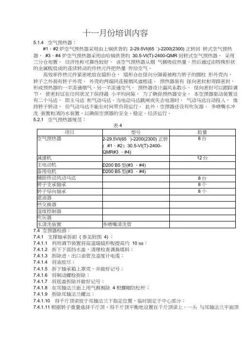
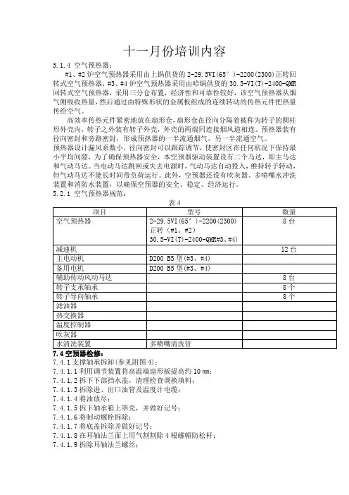
十一月份培训内容5.1.4 空气预热器:#1、#2 炉空气预热器采用由上锅供货的2-29.5VI(65 °)-2200(2300) 正转回转式空气预热器,#3、#4 炉空气预热器采用由哈锅供货的30.5-VI(T)-2400-QMR 回转式空气预热器,采用三分仓布置,经济性和可靠性较好,该空气预热器从烟气侧吸收热量,然后通过由特殊形状的金属板组成的连续转动的传热元件把热量传给空气。
高效率传热元件紧密地放在扇形仓,扇形仓在径向分隔着被称为转子的圆柱形外壳内,转子之外装有转子外壳,外壳的两端同连接烟风道相连。
预热器装有径向密封和旁路密封,形成预热器的一半流通烟气,另一半流通空气。
预热器设计漏风系数小,径向密封可以跟踪调节,使密封区在任何状况下保持最小平均间隙,为了确保预热器安全,本空预器驱动装置设有二个马达,即主马达和气动马达。
当电动马达跳闸或失去电源时,气动马达自动投入,维持转子转动,但气动马达不能长时间带负荷运行。
此外,空预器还设有吹灰器、多喷嘴水冲洗装置和消防水装置,以确保空预器的安全、稳定、经济运行。
5.2.1 空气预热器规范:表47.47.4.1 支撑轴承拆卸( 参见附图4) :7.4.1.1 利用调节装置将高温端扇形板提高约10 ㎜;7.4.1.2 拆下下部挡水盖,清理检查调换填料;7.4.1.3 拆除进、出口油管及温度计电缆;7.4.1.4 将油放尽;7.4.1.5 拆下轴承箱上罩壳,并做好记号;7.4.1.6 将制动螺栓拆除;7.4.1.7 将底盖拆除并做好记号;7.4.1.8 在耳轴法兰面上用气割割除 4 根螺帽防松杆;7.4.1.9 拆除耳轴法兰螺丝;7.4.1.10 将千斤顶梁放于耳轴法兰下指定位置,临时固定于中心部分;7.4.1.11 根据转子重量选择千斤顶,将千斤顶平衡地设置在千斤顶梁上,一头与耳轴法兰平面顶住。
设置好后请有关技术人员来现场检查,认为符合要求时,才能将转子顶高 5 ㎜左右。
1. 目录1.目录 (1)2.安全说明 (2)3.摩擦焊接的原理 (4)4.说明及选用件 (6)5.气动信息 (7)6.操作说明 (8)7.调整 (10)8.拆卸 (14)9.重新组装 (18)10.故障及排除方法 (22)11.零部件清单 (24)12.气动原理图及配件 (25)13.悬挂方式选择 (34)为了您的安全,请在操作前仔细阅读此说明书,并保留此说明书以作备用。
2.安全说明使用该工具前,请仔细阅读此说明书。
1.谨记“安全至上”原则,请正确使用该手动工具2.操作前阅读此说明书3.勿将此工具上的安全部件拆下4.不要撕下或损坏产品上的标签5.不要将手或其它身体部位挡在打包带与包装盒之间此工具是特别为用PET带捆绑物品而设计的。
带的宽度范围:16-25mm勿将打包带作托架使用戴上防护眼镜、耳套、防护手套、防护帽、防护鞋及长袖衬衫,扣好所有钮扣,注意你的领带、长发及衣服不被打包机钩住。
确定空气软管能够承受得住,外侧有抗油污剂。
此工具须设快速切断装置,我们推荐用“HANSEN”快速切断装置,气压不能超过100psi/7巴勿使用瓶装气源机内的空气容易被润滑油污染,困此,适当的通风是完全必要的。
长期接触过量的振动将对操作者的健康有害,必须按IS05349 的有关规定进行操作如果噪音大于85dB(A),操作者须佩戴耳套,即使噪音在85Db(A)以下,也建议用耳套。
拉紧的皮带突然折断,伤及眼睛可能会导致失明,操作时请佩戴防护罩:当切割皮带时,握住皮带上部,人站在皮带边侧,下部分皮带会向下断开,切割皮带时,表注意无人站在旁边。
维护与清洁过程中,使用气枪所造成的灰尘将对眼睛有害。
操作中,可移动部件(紧轮)可能会夹住手套或身体其它部位,当紧轮在转动时,切勿触摸它。
保养好此工具用气枪定期进行检查与维护当挂钩螺松掉时,拧紧它当更换零件时,切断气源固定切刀上的锋利刀片可能会切伤手和手指。
切记,戴上保护手套3.摩擦焊接的原理该工具是一种摩擦焊接型打包机,重叠的热塑性皮带通过摩擦运动产生的热量接合,因此被称为“摩擦焊接”。
气动元件使用说明1气动元件使用说明气压传动系统中,气源处理件是指空气过滤器、减压阀和油雾器,有些品牌的电磁阀和气缸能够实现无油润滑(靠润滑脂实现润滑功能),便不需要使用油雾器!过滤度一般为50-75μm,调压范围为0.5-10mpa,如需过滤精度为5-10μm,10-20μm,25-40μm,及调压为0.05-0.3mpa,0.05-1mpa三大件无管连接而成的组件称为三联件。
三大件是多数气动系统中不可缺少的气源装置,安装在用气设备近处,是压缩空气质量的最后保证。
三大件的安装顺序依进气方向分别为空气过滤器、减压阀和油雾器。
空气过滤器和减压阀组合在一起可以称为气动二联件。
还可以将空气过滤器和减压阀集装在一起,便成为过滤减压阀(功能与空气过滤器和减压阀结合起来使用一样)。
有些场合不能允许压缩空气中存在油雾,则需要使用油雾分离器将压缩空气中的油雾过滤掉。
总之,这几个元件可以根据需要进行选择,并可以将他们组合起来使用。
空气过滤器用作对气源的洁净,可以过滤器压缩空气中的水分,防止水分随其气体步入装置。
减压阀可以对气源展开稳压,并使气源处在恒定状态,可以增大因气源气压变异时对阀门或执行器等硬件的受损。
过滤器用作对气源的洁净,可以过滤器压缩空气中的水份,防止水份随其气体步入装置。
油雾器可对机体运动部件进行润滑,可以对不方便加润滑油的部件进行润滑,大大延长机体的使用寿命。
气源处置件采用表明:1、过滤器排水有压差排水与手动排水二种方式。
手动排水时当水位达到滤芯下方水平之前必须排出。
2、压力调节时,在旋转旋钮前恳请先挤到再转动,甩下转动钮为定位。
转动钮向右为调低出口压力,向左转动为调高出口压力。
调节压力时应逐步光滑地调至所须要压力值,不应当一步调节妥当。
3、给油器的使用方法:给油器使用jisk2213输机油(isovg32或同级用油)。
加油量请不要超过杯子八分满。
数字0为油量最小,9为油量最大。
自9-0位置不能旋转,须顺时针旋气源处置件包含过滤器、减压阀、过滤器减压阀、油雾器以及它们共同组成的二联件、三联件。
十一月份培训内容5.1.4 空气预热器:#1、#2炉空气预热器采用由上锅供货的2-29.5VI(65°)-2200(2300)正转回转式空气预热器,#3、#4炉空气预热器采用由哈锅供货的30.5-VI(T)-2400-QMR 回转式空气预热器,采用三分仓布置,经济性和可靠性较好,该空气预热器从烟气侧吸收热量,然后通过由特殊形状的金属板组成的连续转动的传热元件把热量传给空气。
高效率传热元件紧密地放在扇形仓,扇形仓在径向分隔着被称为转子的圆柱形外壳内,转子之外装有转子外壳,外壳的两端同连接烟风道相连。
预热器装有径向密封和旁路密封,形成预热器的一半流通烟气,另一半流通空气。
预热器设计漏风系数小,径向密封可以跟踪调节,使密封区在任何状况下保持最小平均间隙,为了确保预热器安全,本空预器驱动装置设有二个马达,即主马达和气动马达。
当电动马达跳闸或失去电源时,气动马达自动投入,维持转子转动,但气动马达不能长时间带负荷运行。
此外,空预器还设有吹灰器、多喷嘴水冲洗装置和消防水装置,以确保空预器的安全、稳定、经济运行。
5.2.1空气预热器规范:7.4.1支撑轴承拆卸(参见附图4):7.4.1.1利用调节装置将高温端扇形板提高约10㎜;7.4.1.2拆下下部挡水盖,清理检查调换填料;7.4.1.3拆除进、出口油管及温度计电缆;7.4.1.4将油放尽;7.4.1.5拆下轴承箱上罩壳,并做好记号;7.4.1.6将制动螺栓拆除;7.4.1.7将底盖拆除并做好记号;7.4.1.8在耳轴法兰面上用气割割除4根螺帽防松杆;7.4.1.9拆除耳轴法兰螺丝;7.4.1.10将千斤顶梁放于耳轴法兰下指定位置,临时固定于中心部分;7.4.1.11根据转子重量选择千斤顶,将千斤顶平衡地设置在千斤顶梁上,一头与耳轴法兰平面顶住。
设置好后请有关技术人员来现场检查,认为符合要求时,才能将转子顶高5㎜左右。
7.4.1.12质量标准:a)轴承滚柱表面应光滑,无斑点、裂纹、剥皮现象;b)砂架完整无损,滚柱在砂架中转动灵活;c)调节环固定螺丝不得有损伤;d)调节环结合平面应平整无纹路;e)推力轴承外壳合金钢螺丝不得有损伤;f)轴颈应光洁、平滑,不得有裂纹、凹痕、毛刺等缺陷;g)主轴法兰平面应平整、无毛刺及较严重的碰伤;h)主轴法兰螺丝应无损伤现象,各螺丝紧固力距应一致,法兰螺丝紧固后,两法兰平面应接合严密, 用0.03㎜塞尺检查,塞不进为佳;i)转子标高应检修前、后一致;j)转子中心与密封盖偏心不大于0.2㎜;k)防水密封罩壳装好后,不得有泄漏现象。
空预器变频驱动装置使用说明书(V6.02)西安智通自动化技术开发公司2007年4月目录一、总述 (2)二、主要参数 (2)三、控制接口 (2)1、变频控制柜接受来自DCS的以下干节点控制信号 (2)2、变频控制柜向DCS提供以下干节点指示信号 (2)3、变频控制柜向DCS提供以下模拟量信号 (2)4、空预器变频控制柜上设置以下操作按钮 (2)5、空预器变频控制柜上设置以下信号指示灯 (3)四、控制功能 (3)1、断电检测与电源自动切换 (3)2、驱动装置的启动、运行和停止 (3)3、副驱动特有控制功能 (4)4、故障检测与安全保护 (4)五、设备的数量与布置 (5)一、总述该变频驱动装置用于驱动东方锅炉集团空气预热器工程公司生产的600MW 迴转式空气预热器(后简称空预器)。
该装置可以提升电机启动转矩,降低设备启动过程中的机械冲击和电网冲击,使设备的运行安全、平稳。
空预器分为甲、乙两侧,每一侧空预器分别由独立的驱动装置驱动。
为提高空预器运行的可靠性,每一侧空预器的驱动装置都由主驱动和副驱动组成,并配有手动盘车功能。
正常运行情况下由主驱动拖动空预器运行,在主驱动故障时副驱动将代替主驱动运行。
主驱动、副驱动连锁保护,分别采用不同的供电电源。
主驱动和副驱动分别由控制柜内的两台同型号变频器(AS1、AS2)启动。
完成启动过程后,主、副驱动的电机将自动切换到工频电源运行。
副驱动在清洗模式下一直由变频器AS2拖动,不切换到工频电网。
为提高空预器运行的可靠性,驱动系统配置有气动马达。
当主、副驱动同时故障或系统断电时气源控制阀自动打开,由气马达驱动空预器旋转。
气马达与主副驱动连锁保护,禁止同时运行。
二、主要参数电机类型:380V三相交流异步电机,驱动功率:15kW(主副电机相同),额定电流:I A=32A,电机转速:n=980rpm,启动时间:T=60s。
三、控制接口1、变频控制柜接受来自DCS的以下干节点控制信号1)紧急停机信号, 2)事故复位信号,3)主控/就地选择信号, 4)自动/手动选择信号,5)副驱动正常/清洗速度选择信号 6)主驱动启动信号,7)主驱动停止信号, 8)副驱动启动信号,9)副驱动停止信号, 10)气马达启动信号,11) 气马达停止信号。
空气预热器技术说明2007-9-19空气换热器1、前言冶金行业是国家能源消耗大户,同时也是环境污染的主要制造者之一。
国家制订的可持续发展的长期目标,其重要保证条件就是降低冶金行业能耗,提高能源利用率,减少污染排放,实现和谐发展。
冶金行业要降低能耗,除了改善生产工艺和条件,另外的一个重要途径就是充分利用排放掉的能源,从而提高能源利用效率。
利用排放掉能源的主要设备就是换热器。
管壳式换热器是一种常见的换热设备,已经有近百年的历史。
目前已经已经有非常多的种类,广泛应用于各种行业。
管壳式换热器的特点是:换热空间是管束以及管束外面的壳体与管束形成的空间。
一种流体走管内,另外的流体走管与壳之间。
两种流体通过管壁进行换热。
管壳换热器的优点是应用广泛,可以耐高温高压,可以大型化,它的缺点是传热系数比较低,单位换热面积消耗的金属材料比较多。
为了解决这个问题,人们采取了很多方法来改善管壳换热器的传热条件。
2、螺纹管螺纹管是上世纪末出现的一种异形传热管,它通过对光滑钢管进行压力加工,使其发生螺纹状形变,表面形成螺纹凹槽而成。
螺纹管同光滑管比有非常明显的性能增强:①由于螺纹凹槽的形成,可以使管内气流形成旋流,增强了紊流状态下的对流传热能力;②螺纹凹槽使得管子表面变得粗糙,破坏了气流边界层,使得在层流状态下气体对流传热有明显提高;③螺纹凹槽可使管子传热表面积有所增加;④螺纹管比光滑管的固有频率提高,降低了换热器的振动。
但是螺纹管的阻力比光滑管大,管子刚度也比光滑管小,这是螺纹管存在的缺点。
AA2 机组空气预热器的换热元件就采用单程轧槽螺纹管。
3、换热器结构换热器采用高温列管式,风箱为方形,烟气走管外行程,空气走管内行程。
整个换热器嵌入烟气通道内,没有外壳。
烟气经过换热管外换热后直接排放掉,为一个行程。
空气经过四个管行程被烟气加热,管束用风箱和连接管连接,连接管高温端有膨胀节。
空气流与烟气流呈逆差流的流动分布。
4、换热器参数4.1 烟气参数:入口温度:850C 出口温度:393C烟气量:9636m3/h・C 阻力损失:62Pa烟气放出热量:1.405 x 10⁶kcal/h4.2空气参数:入口温度:20C 出口温度:550 C空气量:7524m3/h・C 阻力损失:770Pa空气吸收热量:1.286X 10⁶kcal/h4.3换热管参数:管子类型:单程轧槽螺纹管光管规格:© 45X 2.5X 1900,中间有折弯管子数量:276 X 4=1104根4.4管子排布:迎风面截距110mm,气流方向截距67mm,三角形错排4.5传热参数:管外传热系数:28.8kcal/m2- h -C管内传热系数:84.1 kcal/m2- h -C综合传热系数:20.8 kcal/m2- h -C传热面积:215m24.6材质:由于换热器管壁温度有超过500C的部分,所以前两行程的管材为1Cr18Ni9Ti ,并且热浸镀渗铝,后两行程的管材为20g, 符合GB3087-99 标准, 样也热浸镀渗铝。

CCN 15284821操作手册66651-B内容: 操作, 安装和维护发布日期: 1-21-00修订:8-1-11(修订版本:02)66651-B 气动马达在安装, 操作或维修本设备之前, 请仔细阅读本手册。
将本技术资料置于操作员手头是雇主的责任。
10" 气动马达6" 行程维修服务包只能用正宗 (原装) 的ARO替换零件, 以确保相容的压力等级和最长的使用寿命。
637110维修服务包包括整台气动马达正常维修服务所必需的软质零件。
637111维修服务包是阀门更换零件包。
一般说明10"气动马达是用于双球或断流止回泵的动力装置。
它采用拉杆结构, 易于分解, 它利用拉杆与下泵端连接, 便于操作。
请参看该泵型操作说明书中的专门说明。
操作和安全预防措施切勿超过最大进气压力90 P.S.I. (6.2巴) 或每分钟75次循环。
警告: 高压设备 - 在试图进行维修服务前, 务必切断气源, 并释放物料压力。
在空气马达上安装一接地片。
该接地片可使泵正确接地。
气体和润滑油要求润滑器上应使用一个能够过滤大于50微米颗粒的过滤器。
经过滤并加过油的空气将使泵更有效地运行, 使工作部件和机构使用寿命更长。
使用一个空气管路润滑器, 并始终提供高等级S.A.E. #90W非去垢齿轮油, 将润滑速率设定到每分钟不超过一滴。
y y y图 1INGERSOLL RAND COMPANY LTD209 NORTH MAIN STREET – BRYAN, OHIO 43506(800) 495-0276 FAX(800) 892-6276© 2011工作原理第 2 页, 共 8 页 66651-B (zh)66651-B (zh)第 3 页, 共 8 页清洁 (39) 阀杆和 (5) 加长杆的螺纹。
在这些螺纹上涂乐泰271, 通过用可调节式老虎钳在螺纹下夹住 (39) 阀杆, 以及在 (5) 加长杆上搭扳手的平面上用一把扳手, 将 (5) 加长杆拧到 (39) 活塞杆上, 并拧紧。
空预器说明书第一篇:空预器说明书空预器我厂空预器型号为LAP10320/883,为容克式预热器,转子直径10320毫米,蓄热元件高度自上而下为800、800和300毫米,下层300毫米冷端蓄热元件为耐腐蚀钢,其余热段蓄热元件为碳钢,本空预器是三分仓型式。
一、原理LAP10320/883这种三分仓容克式空气预热器是一种以逆流方式运行的再生热交换器,加工成特殊波纹的金属蓄热元件被紧密地放置在转子扇形隔仓内,转子以1.14转/分的转速旋转,其左右两半部份分别为烟气和空气通道,空气侧又分一次风道及二次风道,当烟气流经转子时,烟气将热量释放给蓄热元件,烟气温度降低,当蓄热元件旋转到空气侧时,又将热量释放给空气,空气温度升高,如此周而复始地循环,实现烟气与空气的热交换。
转子由置于下梁中心的推力轴承及置于上梁中心的导向轴承支撑,并处在一个九边形的壳体中,上梁、下梁分别与壳体相连,壳体则坐落在钢架上,装在壳体上的驱动装置通过转子外围的围带,使转子以1.14转/分的转速旋转,为了防止空气向烟气泄露,在转子上、下端半径方向,外侧轴线方向以及圆周方向分别设有径向、轴向及旁路密封装置。
二、主要部件及其性能 1.转子本预热器转子采用模数仓格式结构,全部蓄热元件分装在24个扇形仓格内(每个仓格为15°),每个模数仓格利用一个定位销和一个固定销与中心筒相连接,由于采用这种结构,大大减少了工地安装工作量,并减少了转子内焊接应力及热应力,中心筒上、下两端分别用M42合金钢螺栓互相连接,外周下部装有一圈传动围带,围带也分成24段。
热段蓄热元件由模数仓格顶部装入,冷端蓄热元件由模数仓格外周上所开设的门孔装入。
2.蓄热元件热段蓄热元件由压制成特殊波形的碳钢板构成,按模数仓格内各小仓格的形状和尺寸,制成各种规格的组件,每一个组件都是由一块具有垂直大波纹和扰动斜波的定位板,与另一块具有同样斜波的波纹板,一块接一块地交替层叠捆扎而成,钢板厚0.6MM。
LAP13494/3883回转式空气预热器说明书沁北电厂本预热器根据美国C-E预热器公司技术进行设计和制造。
型号LAP13494/3883表示容克式空气预热器,转子直径13494毫米,蓄热元件高度至上而下分别为300、800、800和300毫米,冷段300毫米蓄热元件为低合金耐腐蚀传热元件,其余热段蓄热元件为碳钢,每台预热器金属重量约653吨,其中转子重量约492吨(约占总重75%)。
本空气预热器是三分仓形式。
一原理LAP13494/3883这种三分仓容克式空气预热器是一种以逆流方式运行的再生式热交换器。
加工成特殊波纹的金属蓄热元件被紧密地放置在转子扇形仓格内,转子以0.99转/分的转速旋转,其左右两半部分分别为烟气和空气通道。
空气侧又分为一次风道和二次风道,当烟气流经转子时,烟气将热量释放给蓄热元件,烟气温度降低;当蓄热元件转道空气侧时,又将热量释放给空气,空气温度升高。
如此周而复始地循环,实现空气和烟气热交换。
它不但是电站锅炉的主要部件,而且也是化工、冶金过程中理想的节约能源、提高效率的热交换器。
转子由置于下梁中心的推力轴承及置于上梁中心的导向轴承支撑,并处在九边形的壳体中,上梁、下梁分别与壳体相连,壳体则坐落在钢架上。
电动机安装在下梁的下部,通过与转子接长轴连接,带动转子旋转。
为防止空气向烟气侧泄漏,在转子上、下端半径方向,外侧轴线方向,以及圆周方向分别设有径向、轴向及旁路密封装置,采用双密封结构以降低漏风率。
此外,预热器上还配有火灾检测消防和清洗系统,吹灰装置、润滑及控制等设备(见图1及图2)。
二主要部件1.转子本空气预热器转子采用模数仓格结构,每个仓格为15度,为布置双密封结构,每个仓格又分隔为两(见图4),全部蓄热元件分装在24个模数仓格内,每个模数仓格利用一个定位销和一个固定销与中心筒相连接。
由于采用这种结构,大大减少了工地的安装工作量,并减少转子内焊接应力和热应力。
中心筒上、下两端分别用M12和M42和金螺栓连接上轴和下轴,接长轴通过M42合金螺栓与下轴相连,整体形成预热器的旋转主轴。
29-VI(T)-SMR空气预热器运行和说明书17.YX3300.001编写:张玉珠校对:审核:审定:批准:哈尔滨锅炉厂有限责任公司2003年8月8日目录1.容克式空气预热器的工作原理主要技术规范、重要图纸清单 (2)2.传热元件 (4)3.支承轴承 (9)4.导向轴承 (12)5.转子传动装置 (14)6.空气预热器润滑 (15)7.空气预热器密封 (16)8.空气预热器运行 (22)1前言本说明书参照美国ABB(现为ALSTOM)空气预热器公司提供的典型Ⅵ型半模式结构空气预热器运行和维修说明书编写的。
转子停转报警装置、支承轴承和导向轴承用的油循环设备、着火探测系统、转子传动装置及控制和吹灰器等本文仅作简要概述,详见各有关的说明书。
为转子的圆柱形外壳内,转子之外装有转子外壳,转子外壳的两端同连接烟风道相联。
预热器装有径向密封和旁路密封,形成预热器的一半流通烟气,另一半流通空气。
当转子慢速转动时,烟气和空气交替流过传热元件,传热元件从热烟气吸收热量,然后这部分传热元件受空气流的冲刷,释放出贮藏的热量,这样空气温度大为提高。
本机组的回转式空气预热器为Ⅵ型,三分仓半模式,采用内置式支承轴承。
1.2 主要技术规范传热元件热端 0.5mm FNC型碳钢热端中间层 0.5mm FNC型 CORTEN钢冷端 0.8mm DU3型SPCC-SD钢(搪瓷)转子密封——热端和冷端径向密封片δ= 2.5mm CORTEN钢转子中心筒密封片δ= 6 mm CORTEN钢轴向密封片δ= 2.5mm CORTEN钢旁路密封片δ= 1.5mm CORTEN钢转子传动装置减速机:正常输出轴转速为0.85转/分。
主电机:型号:M2QA-W160M6B B3型 7.5KW,380V,17A ,970 RPM 双轴伸。
备用电机:型号:M2QA-W160M6B B3型 7.5KW,380V,17A ,970 RPM 双轴伸。
转子正常转动速度: 0.85RPM;采用变频调速慢速挡转子转动速度:0.21转/分。
气动元件使用说明一、气动元件的使用环境:一)无腐蚀性气体、无阳光直射、无有机溶剂、无化学药品、无明显粉尘、元爆炸性气体、无强磁的场合。
(二)环境温度一般在5℃~50℃之间。
(三)冲击和振动幅度应在气动元件的允许范围内。
(四)供电电压应在气动元件规定范畴内。
二、对使用气体的要求:(一)使用清洁干燥的压缩空气,根据不同的要求,采用相应的气源处理系统。
不得使用未经任何处理的压缩空气。
(二)在灰尘多、有水滴、油滴的场合应采取防护措施。
(三)冷凝水多、高温高湿的场合,在过滤器前应配置空气干燥器,后冷却器,自动排水器等。
三、气动元件的润滑:(一)为延长气动元件的使用寿命,除不供油润滑的元件外,一般应给油润滑。
给油时应选用流量合适的油雾器。
要用符合ISO VG32标准的专用润滑油(本公司供应此种润滑油)不得使用机油、锭子油等对气动密封件有害的润滑剂。
(二)润滑方法将油雾器的注油塞拧下,将专润滑油注入油杯内(亦可拧下油杯注油后再把油杯拧好),测量为油杯容积的80%左右为宜,同时调节滴油速度,使每1m3空气中含有0.5至5滴润滑油即可。
检查润滑是否良好,可以将一张清洁的白纸,放在换向阀的排气孔附近,阀工作三至四个循环后,若纸上只有很轻的斑点,表明润滑良好。
(三)对于不给油润滑的元件,一旦给油后,不得停止给油,否则会导致元件工作不良。
(四)更换气动元件的密封件时,在密封件上一定要涂抹规定的润滑油,否则会操作密封件。
四、常用气动元件应用及使用注意事项:<一>配管及管接头:1、应根据气动系统和气动元件对空气流量,安装方式的不同要求应用相应的配管和管接头。
2、配管前应吹净或洗净管内的油污、灰尘、金属屑,配管于管接头及气动元件连接时不允许将上述杂物及密封带的碎屑及粘接剂混入。
3、管接并没有安装时,请用六角扳手紧固,用力应适宜,否则会损坏元件、伤害人体或造成密封不良。
所以要求按下列数据接管。
4、用密封生料带缠绕时,留出1.5~2道丝扣,并按下图(图三)所示的方向缠绕。
Operating Instructions for:15900-15910-15910C15920-15930-15930C15940-15950-15950CRev 07/08AIR HYDRAULIC PUMPMax. Pressure: Check Data Plate for Max PressureWorkstation Sound Pressure Level: 83 dB(A) at Rated CapacityDefinition: An air hydraulic pimp delivers hydraulic fluid under pressure through the use of compresses air as a power source.SAFETY EXPLANATIONSTwo safety symbols are used to identify any action or lack of action that can cause personal injury. Your reading and understanding of these safety symbols are very important-Danger is used only when your action or lack of action will cause serious human injury or death.- Warning is used to describe any action or lack of action where a serious injury can occur. IMPORTANT – Important is used when action or lack of action can cause equipment failure, either immediate or over a long period of time.: It is the operator’s responsibility to read and understand the following safety statements, •Only qualified operators should install, operate, adjust, maintain, clean, repair, or transport this machinery•These components are designed for general use in normal environments. These components are not specifically designed for lifting and moving people, agri-food machinery, and certain types of mobile machinery or special work environments such as: explosive, flammable or corrosive. Only the user can decide the suitability or this machinery in these conditions or extreme environments. AME will supply information necessary to help make these decisions.These instructions are intended for end-user application needs. Most problems with new equipment are caused by improper operation or installation. Detailed service repair instructions or parts list can be obtained from AME.Operating InstructionsSAFETY PRECAUTIONSGeneral Operation•All WARNING statements must be carefully observed to help prevent personal injury.•Before operating the pump, all hose connections must be tightened with the proper tools. Do not over tighten.Connections should be only be tightened securely and leak-free. Over tightening can cause premature thread failure or high pressure fittings to split at pressures lower than their rated capacities.•Should a hydraulic hose ever rupture, burst, or need to be disconnected, immediately shut off the pump and release all pressure. Never attempt to grasp a leaking pressurized hose with your hands. The force of escaping hydraulic fluid could cause serious injury.•Do not subject the hose to potential hazard such as fire, sharp surfaces, extreme heat or cold, or heavy impact.Do not allow the hose to be altered or kink, twist, curl, crush, cut, or bend so tightly that the fluid flow within the hose is blocked or reduced. Periodically inspect the hose for wear, because any of these conditions can damage the hose and possibly result in personal injury.•Do not use the hose to move attached equipment. Stress can damage hose and possibly cause personal injury.•Hose material and coupler seals must be compatible with the hydraulic fluid used. Hoses also must not come in contact with corrosive materials such as creosote-impregnated objects and some paints. Consult the manufacturer before paining a hose. Hose deterioration due to corrosive materials can result in personal injury.Never pain the couplers.•Inspect machine for wear, damage and correct function before each use. Do not use machinery that is not in proper working order, but repair or replace it as necessary.•Replace worn or damaged safety decals.•Modification of a product requires written AME authorization.•Use only components with the same pressure rating when assembling a system or machine.Pump•Do not exceed the hydraulic pressure rating noted on the pump data plate or tamper with the internal high pressure relief valve. Creating pressure beyond the rated pressure can result in personal injury.•Before replenishing the fluid level, retract the system to prevent overfilling the pump reservoir. An overfill can cause personal injury due to excess reservoir pressures created when cylinders are retracted.Air Supply•Shut off and disconnect the air supply when the pump is not in use or before breaking any connections in the system.PREPARATION & SET-UPAir Supply Hook-UpRemove the thread protector from the air inlet of the pump. Select and install the threaded fittings which are compatible with your air supply fittings. The air supply should be 20 CFM (.57 M3/min.) and 100 PSI (7 BAR) at the pump to obtain the rated hydraulic pressure. Air pressure should be regulated to a maximum of 140 PSI (9 BAR). Secure your pump fitting to the air supply. See illustrations on following pages.: If improperly used, pressurized equipment can be potentially hazardous. Therefore: •Hydraulic connections must be securely fastened before building pressure in the system.•Release all system pressure before loosening any hydraulic connection in the systemVenting the ReservoirTo improve hydraulic fluid delivery and increase useable hydraulic fluid capacity,Remove shipping plug and install filler/vent cap before using the pump.InstructionsOperatingHydraulic ConnectionsClean all the areas around the fluid ports of the pump and cylinder. Inspect all the threads and fittings for signs of wear or damage and replace as needed. Clean all hose ends, couplers and union ends. Remove the thread protectors from the hydraulic fluid outlets. Connect the hose assembly to the hydraulic fluid outlet and couple the hose to the cylinder. See illustrations below.IMPORTANT: Seal all external pipe connections with a high-grade, non-hardening thread sealant. Teflon tape may also be used to seal hydraulic connections, provided only one layer of tape is used. Apply the tape carefully, two threads back, to prevent it from being pinched by the coupler and broken off inside the system. Any loose pieces of tape could travel through the system and obstruct the flow of fluid or cause jamming of precision-fit parts.This pump is equipped with a two position, 3-way / 4-way control valve for operating single- or double acting hydraulic cylinders and requires attaching the hoses in the following manner:When using a single-acting cylinder, attach one end of a hose to port ‘’A’’ of valve and the end of the hose to the advance port ‘’C’’ of the cylinder. Then Install a pipe plug in valve port ‘’B’’. If the hoses are frequently connected and disconnected, quick couplers should be used to prevent wear and tear on the fittings.When using a double-acting cylinder, attach one hose to port ‘’A’’ of valve and the other end of the hose to the advance port ‘’C’’ of cylinder. Attach the second hose to valve port ‘’B’’ and the other end of the hose to cylinder.ofportreturn‘’D’’Operating InstructionsFor Remote Controlled Pumps:1.Connect the pump to a remote 3-way/4-way valve2.Connect the fluid line from the pressureport on the manifold to the pump pressureport on the valve.3.Connect the fluid line from the fluidreturn port on the manifold to the pumpreturn port on the valve.4.Connect the cylinder(s) to the valve.IMPORTANT: On all single pressure lineapplications, plug one port on the valve.1.Connect the ports of the pump valve toCylinder(s). When port ‘’A’’ ispressurized port ‘’B’’ becomes the return.When port ‘’B’’ is pressurized, port ‘’A’’becomes the return.2.Place the valve into the ‘’A’’ or ‘’B’’Position in order to pressurize thecylinder(s) or start the pump.Operating InstructionsOPERATIONPICTOGRAM DEFINITIONSActivating the pump with the pedal end marked with this pictogram,the flow of fluid is directed out of the reservoir.Activating the pump with the pedal end marked with this pictogram,the flow of fluid is directed back to the reservoir.Priming the Pump UnitUnder certain circumstances it may be necessary to prime the pump unit. To accomplish this, perform the following procedure:For Hand/Foot Operated Pumps:1.Press the release end of the pedal while holding down the air intakeValve with a flathead screwdriver. The air intake valve is locateddirectly under the pedal in the area marked . The Valve isdepressed simultaneously with the area of the pedal duingprinting.2.Allow the pump to cycle approximately 15 seconds.3.Remove the screwdriver, and press end of the pedal oncemore.4.If the cylinder extends or pressure builds, the pump has beensuccessfully primed. If the pump does not respond, repeat theprocedure, jogging the air intake valve while holding the pedal inthe position.For Manual Valve Operated Pumps:Disconnect the hose end at the advance port of the cylinder. Direct the hose end into a suitable container or back into the pump reservoir. Shift the valve to the ADVANCE position and depress the end of the foot pedal inscribed with. Allow the pump to cycle until the fluid begins to flow freely into the container or reservoir. Reconnect the hose end to the cylinder advance port. Shift the valve to the Advance position and reactivate the pump. If the cylinder extends or builds pressure, the pump has been successfully primed. If not refer to the Trouble - Shooting Guide of these instructions.For Remote Controlled Pumps:Depress the AND buttons on the remote hand control simultaneously and allow the pump to cycle for approximately fifteen seconds. Release both buttons and then depress the button once more. If the cylinder extends or pressure builds, the pump has been successfully primed. If the pump does not respond repeat the procedure. If the pump still does not respond, tip pump upside down and repeat procedure.For Tandem Pumps:1.Connect the fluid line to the pressure port and keep the return port plugged. Place the other end of the fluid linein the pump filler hold.NOTE: If the fluid lines are connected to a remote valve, shift the valve into the center position and plug both cylinder ports on the valve. This lets fluid circulate through the valve and back to the pumpreservoir; thereby allowing the pump to prime.2.Attach air line with shut-off valve to the pump.3.Open the air valve, Pump will begin to reciprocate, and fluid will advance through the hose or fluid line andreturn to the pump reservoir. Allow the pump to cycle approximately 15 seconds.4.Plug the manifold pressure port, or shift the valve to pressurize the circuit.if the pump builds pressure, it has been successfully primed.Operating InstructionsPump OperationFor Hand/Foot Operated Pumps:1.To extend the cylinder, depress the pedal on the end marked2.To hold the cylinder in position, release the end of foot pedal marked with to deactivate the pump.3.To retract the cylinder, depress the pedal on the end marked .For Remote Controlled Pumps:1.To extend the cylinder, depress the button on the remote hand control marked2.To hold the cylinder in position, release the button.3.To retract the cylinder, depress the button on the remote hand control markedFor Manual Valve Operated Pumps:1.To extend the cylinder, shift the valve handle to the advance position and depress the end of the foot pedalinscribed with to activate the pump.2.To hold the cylinder in position, release the end of foot pedal inscribed with to deactivate the pump.3.To retract the cylinder, shift the valve handle to the retract position and depress the end of the foot pedalinscribed with to activate the pump.For Pumps with Air Regulators:1.Open the air shut-off valve (if so equipped) or connect the air quick coupler (if so equipped).NOTE: under certain circumstances the pump may need to be primed before operation. Refer to the method described in the section entitled ‘’Priming the Pump Unit.’’2.Slowly turn the air regulator control on unit clockwise to increase pressure, counterclockwise to decreasepressure. As air is admitted to the pump unit, It will begin to deliver fluid to the system. Continue to slowly turn the air regulator control clockwise until the gauge reads the maximum hydraulic pressure rating as stated on the pumps data plate. A maximum hydraulic pressure reading should be obtained if air pressure is approximately 100 PSI (7 BAR).3.Cycle the system several times by manually shifting the 3-way/4-way valve (if so equipped) or the remote valve(if so equipped). Set the air regulator to obtain the desired hydraulic pressure. When decreasing pressure, shift the valve after each adjustment before measuring actual hydraulic pressure.4.Shut off and disconnect air supply to the pump and shift pump valve (if so equipped) or remote valve (if soequipped) two times to release all system pressure. Check fluid level with hydraulic system retracted. The pump is now ready for operation.NOTE: • The Hydraulic pressure is increased or decreased by adjusting the air inlet pressure at the regulator.•On two stage pumps, the air pressure regulator that is mounted on the pump controls only the output from the high pressure stage. The output of the low pressure stage of the pump is determined by the air line pressure coming from the remote regulator. A remote regulator is required to control the air pressure from the air line. The independent functioning of the low and high pressure stages of this pump can best be described as follows. At the minimum air line pressure of 40 PSI (3 BAR), the low pressure stage of the pump will deliver 480 PSI (33 BAR) hydraulic pressure (with the pump regulator turned counterclockwise to prevent air pressure from activating the high pressure stage of the pump.) At the minimum air line pressure (with the pump regulator turned clockwise to allow air pressure to reach the high pressure stage.) Always remember that the pump regulator must be turned fully counterclockwise when the pump is used to produce 1,200 PSI (83 BAR) or less.Operating InstructionsRefilling the ReservoirIf the additional fluid must be adder to the reservoir, use only approved hydraulic fluid (215 SSU @ 1000 F [380 C]). Clean the entire area around the filler plug before adding fluid to the reservoir. Remove the filler plug, and insert a clean funnel with filter. The cylinder must be fully retracted and the air supply disconnected when adding the fluid to the reservoir.Periodic CleaningIMPORTANT: The greatest single cause of failure in hydraulic pumps is dirt. Keep the pump and attached equipment clean to prevent foreign matter from entering the system.A routine should be established to keep the pump as free from dirt as possible. All unused couplers must be sealed with thread protectors. All hose connections must be free of grit and grime. Any equipment hooked up to the pump should also be kept clean. Use only approved hydraulic fluid in this unit and change as recommended (every 300 hours).ACCESSORIESGauges and accessories may not be included with the pump. However, a hydraulic gauge is strongly recommended whenever the pump is used.•The Gauge must be of the proper rating for pressure used!• Use only approved accessories, hydraulic fluid, and repair parts!Installing an In-line Air Pressure Gauge1.Remove the male fitting from the air filter and install a tee adapter, with gauge, between the hose and air filter.2.Install male fitting into the tee adapter and securely clamp the hose to the male fitting.Installing an In-line Hydraulic Pressure Gauge1.Remove the thread protector from the hydraulic outlet port and inspect the threads and fittings for signs of wear.2.Install a tee adapter, with gauge, between the hose coupling and the pump hydraulic outlet port.3.Tighten all connections securely! DO NOT OVERTIGHTEN HOSE CONNECTIONS.Fire-Resistant Hydraulic FluidFlame Out 200TM fire-resistant hydraulic fluid is compatible with all AME hydraulic equipment. The use of this fluid does not require the changing of seals in any AME pump or cylinder and is available through your local Hydraulic Fluid Distributor.Operating InstructionsPREVENTIVE MAINTENANCEIMPORTANT: • Any repair or servicing that requires dismantling the pump must be performed on a dirt-free environment by qualified technician.• Dispose of machine and fluids properly.LubricationFor Hand/Foot, Manual Valve, and Remote Control Operated Pumps:If the pump is operated on a continuous duty cycle for extended periods, the manufacturer recommends installing an automatic air line oiler in the air inlet line as close to the pumping unit as possible. Set the unit to feed approximately one drop of oil per minute into the system. Use SAE grade oil, 5W to 30W.For Tandem Pumps:These models have an integral air pressure regulator, air filter and lubricator. Set the lubricator to feed one drop of oil per minute to the system. Use SAE grade oil, 5W to 30W. For serving the air regulator, lubricator and filter system see the operating and service instructions provided.Bleeding Air from the SystemDuring the first moments of operation or after prolonged use, a significant amount of air may accumulate within the hydraulic system. This entrapped air may cause the cylinder to respond slowly or behave in an unstable manner. To remove the air, run the system through several cycles (extending and retracting the cylinder) free of any load. The cylinder must be at lower level then the pump to allow air to be released through the pump reservoir.Inspecting the Hydraulic Fluid LevelCheck the fluid level in the reservoir after every 10 hrs of use. Drain and replenish the reservoir with Approved hydraulic fluid after every 300 hours of use approximately.For Pumps with 105 cubic Inch (1.7 l) reservoir capacity:The fluid level should be inch (12.7 mm) from the filler/vent cap with all cylinders retractedFor pumps with a 2 gallon (7.6 l) reservoir capacity:The fluid level should 1-3/4 inch (44.5 mm) from the filler/vent cap with all cylinders retracted.Draining and Flushing the ReservoirIMPORTANT: Wipe the pump exterior completely clean before attempting this procedure!1.Remove the screws that fasten the pump assembly to the reservoir. Remove the pump assembly fromthe reservoir. Do not damage the gasket, filler or safety valve.2.Drain the reservoir of all fluid and refill half full with clean hydraulic fluid. Rinse the filter clean.3.Place the pump assembly back onto the reservoir, and secure with two of the machine screwsassembled in opposite corners of the housing.4.Run the unit for several minutes. Use the same method described in the section titled ‘’Priming thePump Unit.’’5.Drain and clean the reservoir once more.6.Refill the reservoir with Approved hydraulic fluid and replace the pump assembly (with gasket) on thereservoir pounds (2.8 to 3.4 N•m); for 2 gallon (7.6 l) reservoirs, torque to 35 to 45 inch pounds (4.0 to 5.0 N•m)IMPORTANT: Drain and clean the other hydraulic system components (hoses, cylinders, etc.) before reconnecting them to the pump. This will prevent contaminated fluid from entering the pump again.Operating InstructionsOPERATOR TROUBLESHOOTING GUIDEIf this guide does not resolve your pump problem,Contact an authorized hydraulic service center or a company headquarters listed on back sheet 5 of 5.PROBLEMS CAUSE SOLUTIONPump reciprocates but no fluid 1. Low Fluid Level 1. Add fluid as instructed innot PreventiveSection.Maintenancewill(cylinderfluiddeliveryextend) 2. Pump not primed. 2. Prime pump as instructed inSection.Operation3. Fluid intake filter contaminated 3. Remove reservoir and clean intakeand reinstall.Low fluid delivery (cylinder 1. Inadequate air supply 1. a. Should be 20 CFMextends slowly) a. Check air input supply. (.57 M3/min.) Minimum.b. Contamination, check air side b. Clean and reassemble.of pump (plugged air inletscreen.)reservoirRemovecleana.and2.2.HydraulicFailurea. Check the fluid inlet filter for intake filter and reinstall.contamination. b. Bleed the system asb. Air in hydraulic system. described in the PreventivesectionMaintenancePump will not build to maximum 1. Check the air supply. 1. 100 PSI (7 BAR) is required tomaximumleakage) obtainpressure.(visiblepressurenoaccordinginstructions2.toAdjust2.Pressureregulatorimproperlyadjusted (if so equipped). in Operation sectionPump builds pressure but will not 1. Check the hydraulic connections 1. Refit or repair as needed.hold system pressure and other system componentsfor leakage, including 3 way/4soequipped).(ifvalvewayPump will continue to run slowly 1. Output pressure equal to or 1. Normal Operation.even after desired pressure is higher than relief valve settingor 2.Repairorreplace.valve3-way/4-wayreached2.Defectiveleaking.othercomponentsExcess of oil spray from muffler 1. Air lubricator is set too rich ( if so 1. Set at one drop per minute.equipped).。
气动马达的运行和维修的注意事项
在使用和维修气动马达时,需要注意以下事项:
1. 运行注意事项:
- 确保气源干燥:使用气动马达时,应提供干燥的气源,避
免潮湿的气体进入马达内部,以免影响正常运行和损坏部件。
- 适当的气源压力:根据气动马达的设备说明书或厂家建议,设置适当的气源压力,过高或过低的压力都可能导致马达性能下降或损坏。
- 避免过载:避免马达超载运行,确保其在额定负载范围内
操作,以防止过度磨损和损坏。
- 注意温度控制:气动马达运行时产生摩擦和热量,应注意
合理的温度控制,避免马达过热。
2. 维修注意事项:
- 定期维护:按照设备说明书或厂家建议,定期对气动马达
进行维护,包括清洁、润滑、更换密封件等,以保持其正常工作状态。
- 选择合适的润滑剂:使用适当的润滑剂对气动马达进行润滑,可减少摩擦和磨损,延长使用寿命。
需确保所选润滑剂与马达材料和应用环境相兼容。
- 小心处理磨损件:在更换磨损部件时,谨慎操作,遵循正确的拆卸和安装程序,确保正确匹配和定位零件,并使用正确的工具进行维修。
- 注意安全:在进行气动马达维修过程中,注意工作安全。
确保马达停止工作并减压后,方可进行拆卸和维修操作。
总之,正确的运行和维护气动马达可以提高其性能和可靠性,延长使用寿命,并确保操作的安全性。
建议根据具体的气动马达型号和制造商的建议,遵循相应的操作和维护指南。