氧压机说明书.docx
- 格式:docx
- 大小:88.45 KB
- 文档页数:10
目录1、一般安全要求: (2)2、主要技术规格 (4)3、结构概述、工作原理及用途 (5)4、主要部件的结构说明 (6)5、存放与保管 (7)6、安装 (8)7、启封和组装 (9)8、运转前的准备工作 (11)9、压缩机的日常操作 (13)10、日常维护和检修 (14)11、封存 (16)资料来源编制校对标准化提出部门审定标记处数更改文件号签名日期批准文号批准1、一般安全要求:1.1 通用安全要求压缩机的操作人员必须经过正式培训,在熟知压缩机的结构、原理和说明书以及正确掌握操作方法和安全防范措施的基础上方能上岗操作。
在没有认真进行安全检查的情况下,不可轻易启动压缩机。
任何违反安全规程的操作都可能导致设备的损坏或危及人身安全。
在改动压缩机系统的任何部位前,应事先与制造厂家的设计部门取得联系。
1.2 受压部件安全要求压缩机气路系统中的缓冲罐、中间冷却器、气液分离器及贮气罐等均为受压部件,凡属压力容器的,用户在安装之前,应与当地劳动部门取得联系,并接受监察。
安全阀及安全附件应妥善维护和定期校验。
严禁压缩机系统超温、超压运行。
当压缩机处于运行中或系统内存有压力时,不得紧固螺栓或拆卸受压零部件(包括曲轴箱堵、盖)1.3 防火与防爆要求对于压缩易燃易爆或有毒气体的压缩机,其安装、使用和操作应符合有关规定。
在通入易燃易爆气体之前必须先用氮气或惰性气体将压缩机系统中的空气置换干净。
站房内应有防止有害气体泄漏后聚积的措施。
气路系统中对外排放口(安全阀的释放口、冷却器的排污口等)应加接导管,引到室外的安全地带放空或集气回收。
电器设备应符合压缩介质所需的防爆等级要求。
1.4 润滑油要求压缩机应使用制造厂家指定的牌号的润滑油,其质量要求应符合标准规定,不同型号的润滑油不得混用。
润滑油应定期更换。
1.5 冷却水要求冷却水应保持清洁,以防水道结垢。
冷却水的水质要求为:1.5.1 有机的和机械的杂质和悬浮物应小于100mg/L,含油量小于5mg/L;1.5.2 接近于中性,即PH值6.5~9;1.5.3具有热稳定性,暂时硬度小于10°(注:硬度1°相当于1L水中,含有10mg的CaO或19mg的MgO)若水质未达到上述要求,应进行过滤和净化。
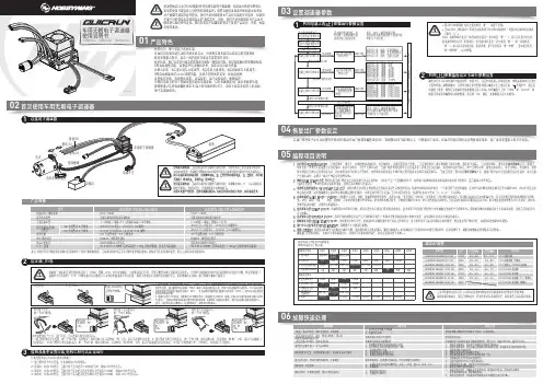
0103设置调速器参数04恢复出厂参数设定利用电调上的SET按键进行参数设置1利用LED参数编程设定卡进行参数设置2设定油门行程23) 刹车时,红色LED恒亮;当油门处于反向最大且最大刹车力度设为100%时,绿色LED也会点亮。
4) 倒车时,红色LED恒亮;当油门处于反向最大且最大倒车力度设为100%时,绿色 LED 也会点亮。
06故障快速处理在油门摇杆处于中立点位置的任意时刻(除进行油门校调或编程设定时),连续按住SET键3秒以上,可恢复出厂设定。
红绿灯同时闪烁时表示恢复设定成功,出厂设定需重新上电方可生效。
10BL60 / 10BL120 Sensored车用无刷电子调速器使用说明书05编程项目说明1. 运行模式(Running Mode):“正转带刹车”模式下,车辆仅能前进和刹车,但不能倒车,该模式通常用于竞赛;“正反转带刹车”模式则提供了倒车功能,通常用于训练。
“正反转带刹车”模式采用双击式倒车方式,即油门 摇杆在第一次从中点区域推至反向区域时,电机只是刹车,不会产生倒车动作;当油门摇杆快速回到中立点区域并第二次推至反向区域时,如果此时电机已停止,则产生倒车动作,如果电机未停止,则不会倒车,仍是刹车,需要 再次将油门回到中点并推向反向区,此时如果电机已经停止才会倒车,这样做的目的是防止车辆行驶过程中因多次点刹而造成误倒车。
“直接正反转”模式采用单击式倒车方式,即油门摇杆从中点区域推至反向区域时,电机立即 产生倒车动作,该模式一般用于攀岩车等特种车辆。
2. 拖刹(Drag Brake)力度: 拖刹是指当油门摇杆从正向区域转入中点区域内时,对电机产生一个微量的刹车力,这样做可以模拟有刷电机的碳刷对电机转子的阻力,适合减速入弯等场合。
(值得注意的是,拖刹会消耗比较多的电量,选择合适的拖刹力度即可)。
3. 电池低压保护阈值(Low Voltage Cut-Off): 这项功能主要是防止锂电池过度放电而造成不可恢复的损坏。

精品文档,你值得期待ZW-25/30型氧气压缩机使用维护说明书0355.SY编制:校对:审核:苏州制氧机有限责任公司二○○八年八月目录一、主要技术规范 (3)二、氧压机简述 (3)三、氧压机的安装要求 (5)四、氧压机的试运转 (8)五、氧压机的正常操作 (9)六、氧压机可能发生的故障及其排除 (10)七、氧压机的检修 (12)八、氧压机的密封和启封 (12)九、交货技术条件 (13)在机器安装以前, 凡与氧气接触的零件表面和管道内部角落, 均应严格去油!一、主要技术规范(一)型式:立式、三列、三级、双作用、气缸无油润滑、水冷式。
(二)排气量:1500m3/h(吸入状态)(三)吸入介质状态:1、介质:干燥氧气2、进气压力:10kPa(G)3、进气温度:20℃(四)最终压力:3.0MPa(G)(五)末级冷却器后气体温度:≤40℃(六)冷却水进口温度:≤32℃(七)气缸直径:一级Ф470mm二级Ф275mm三级Ф165mm(八)活塞行程:220mm(九)曲轴旋转方向:从油泵端看为逆时针方向(十)传动方式:用刚性联轴器与电机直接联接(十一)轴功率:270kW(设计工况)(十二)总重量:22500kg(最大件重量4400kg)(十三)配用电动机:三相异步电动机1.型号:Y500-12型2.功率:315kW3.电压:380kV5.频率:50Hz6.转速:495r/min(十四)冷却水压力:~0.35MPa(表压)(十五)冷却水耗量:48t/h(十六)润滑油循环量:55L/min(一次灌注量300L)N68机械油(十七)齿轮油泵电机功率1.5kW(十八)真空泵电机功率0.55kW二、氧压机简述本机主要由曲轴箱、机身、曲轴、连杆、十字头、气缸、活塞、活门、密封器、气体冷却器、齿轮油泵、油冷却器、氧气过滤器、油过滤器、止回阀门、缓冲器、油蒸汽抽吸系统、氧压机启动柜及仪表柜、电动机等部件组成。
曲轴箱和机身在曲轴中心线处,上下对合构成机座。
共10 页第 1 页YY5201. SMZW-84/30型氧气压缩机使用说明书YY5201 SM开封黄河空分集团有限公司二〇〇八年元月本机各气缸均为铸铁气缸,由缸体、缸头、阀罩和阀盖等零件组成。
气阀配制在缸体侧面,缸体和缸头上有冷却水套,冷却气缸、气阀和填函。
4.7活塞本机各级活塞体均由铝合金制成。
活塞杆材料为不锈钢,表面经高频淬火,具有高耐磨性能,活塞杆与十字头螺纹联接,转动活塞杆即可调整活塞上下死隙。
导向环和活塞环材料均为填充聚四氟乙烯,具有良好的自润滑及耐磨性能。
导向环整体热套在活塞体上,克服了缺口环承受背压的缺点,并能保证在正常运转中不松动,从而控制了环与气缸间合适的工作间隙,因而大大延长了导向环和活塞环的使用寿命,同时还提高了压缩机的容积效率和绝热效率。
活塞环采用斜切口,漏损较小,安装时注意各环开口应错开一定角度。
由于聚四氟乙烯塑料热膨胀系数大,装配时应特别注意活塞环与环槽之间的间隙应在图纸规定的范围之内,过小的侧隙会使活塞环在运动时受热膨胀而卡死在槽内,从而迅速发热损坏。
4.8填函各级填函结构相同,由七盒组成。
每盒均由不锈钢密封盒、装在盒内的三、六瓣密封圈、阻流圈和紧箍在密封圈外缘的弹簧组成。
各填料盒、填函座和填料压盖用两个M8的螺钉联接在一起,然后再整体固定到气缸上,这样便于安装和拆卸。
安装填函时应该注意:a.彻底除净各密封圈毛刺,并用四氯化碳清洗干净。
b. 将密封圈套在Φ73h6圆柱上(或活塞杆上)作轴向漏光检查,除切口处外,各贴合面均不应漏光,否则不予采用(允许小修)。
c. 同一密封盒内,三瓣密封圈应装在靠近气缸一侧。
4.9刮油器刮油器主要由刮油器体、刮油环、弹簧、压盖等零件组成。
刮油环用弹簧箍住,从而使之抱紧活塞杆。
使用前,刮油环需进行刮研,保证与活塞杆很好贴合,以刮净活塞杆上沾附的润滑油,防止润滑油进入填函和气缸中。
装拆刮油环时应注意:a. 刮油环应彻底清除毛刺,但刃口应保持尖锐,装拆时应注意切勿碰伤,以免影响刮油效果。
ZW-84/30型氧气压缩机使用说明书YY5201 SM开封黄河空分集团有限公司二〇〇八年元月目次1 概述 ------------------------------------------------------------------------------------------ 32 主要性能参数 ------------------------------------------------------------------------------ 33 各系统说明 --------------------------------------------------------------------------------- 44 主机主要部件和机组辅助设备说明 --------------------------------------------------- 55 压缩机的主要装配间隙表 --------------------------------------------------------------- 86 压缩机正常开车时的运转参数表 ------------------------------------------------------ 87 压缩机主要零部件、备件和专用工具清单 ------------------------------------------ 91概述ZW-84/30型氧气压缩机为立式、四级四列、双作用、水冷却、无润滑、活塞式氧气压缩机。
可用于大中型空分设备和石油化工等其它工业部门。
该机主要特点为:a. 结构紧凑、占地面积小、重量轻。
b. 动力平衡性好、运转平稳可靠。
c. 振动和噪音小。
d. 运转经济性好。
e. 导向环、活塞环、填料磨损均匀、寿命长。
f.外形美观。
2主要参数3各系统说明请参阅YY5201 LC流程图。
3.1气体系统低压氧气,经吸入滤清器过滤,再经各级压缩及冷却后,送往各使用单位。
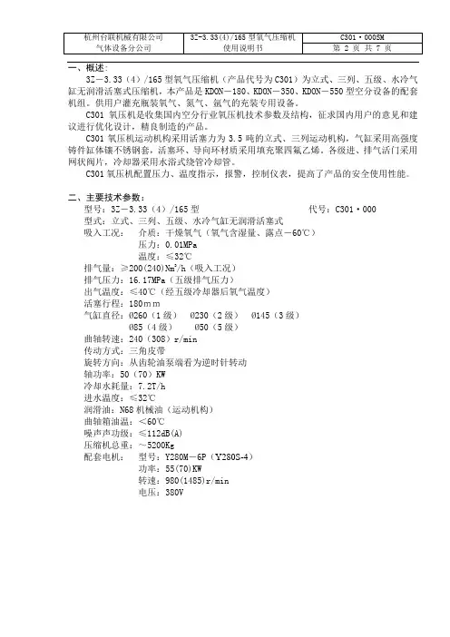
一、概述:3Z-3.33(4)/165型氧气压缩机(产品代号为C301)为立式、三列、五级、水冷气缸无润滑活塞式压缩机,本产品是KDON-180、KDON-350、KDON-550型空分设备的配套机组。
供用户灌充瓶装氧气、氮气、氩气的充装专用设备。
C301氧压机是收集国内空分行业氧压机技术参数及结构,征求国内用户的意见和建议进行优化设计,精良制造的产品。
C301氧压机运动机构采用活塞力为3.5吨的立式、三列运动机构,气缸采用高强度铸件缸体镶不锈钢套,活塞环、导向环材质采用填充聚四氟乙烯。
各级进、排气活门采用网状阀片,冷却器采用水浴式绕管冷却管。
C301氧压机配置压力、温度指示,报警,控制仪表,提高了产品的安全使用性能。
二、主要技术参数:型号:3Z-3.33(4)/165型代号:C301·000型式:立式、三列、五级、水冷气缸无润滑活塞式吸入工况:介质:干燥氧气(氧气含湿量、露点-60℃)压力:0.01MPa温度:≤32℃排气量:≥200(240)Nm3/h(吸入工况)排气压力:16.17MPa(五级排气压力)出气温度:≤40℃(经五级冷却器后氧气温度)活塞行程:180mm气缸直径:Ø260(1级)Ø230(2级)Ø145(3级)Ø85(4级)Ø50(5级)曲轴转速:240(308)r/min传动方式:三角皮带旋转方向:从齿轮油泵端看为逆时针转动轴功率:50(70)KW冷却水耗量:7.2T/h进水温度:≤32℃润滑油:N68机械油(运动机构)曲轴箱油温:<60℃噪声声功级:≤112dB(A)压缩机总重:~5200Kg配套电机:型号:Y280M-6P(Y280S-4)功率:55(70)KW转速:980(1485)r/min电压:380V三、结构简述:C301氧压机为立式、三列、五级、活塞式压缩机,由运动机构(机身、曲轴、连杆、十字头、齿轮油泵、润滑系统、刮油器)、中间座、气缸、活塞、活门、密封器、冷却器、过滤器、气路系统、水路系统、仪电控系统、电动机等部机组成。
氧压机说明书
一、产品概述
氧压机是一种用于将空气中的氧气进行压缩储存的设备,主要用于医疗、实验室和工业领域。
本说明书将为您详细介绍氧压机的使用方法、注意事项及维护保养等内容。
二、产品特点
1. 高压氧气输出:氧压机具备高压输出的能力,可将空气中的氧气高效压缩,满足不同领域的应用需求。
2. 稳定性强:氧压机采用先进的压力控制技术,确保输出氧气的稳定性和精准度,使用户能够享受到可靠的氧气供应。
3. 操作简便:氧压机配备直观的操作面板和简单的控制按钮,用户只需简单的操作即可实现氧压机的启停和压力调整等功能。
4. 安全可靠:氧压机具备多项安全保护功能,如过载保护、过压保护和过热保护等,确保用户在使用过程中的安全。
三、使用方法
1. 首先,将氧压机放置在平稳的地面上,并确保周围空气流通良好。
2. 连接氧气供应管道。
将一端连接到氧气源,另一端连接到氧压机的进气口。
3. 打开氧压机的电源开关,并调整压力控制旋钮,使其适应您所需的氧气输出压力。
4. 等待氧压机自动启动,当达到设定压力后,进气自动停止。
此时,您可以通过出气口连接所需的氧气设备或储存罐。
四、注意事项
1. 严禁在氧压机周围进行明火操作,以免引发火灾或爆炸。
2. 长时间使用氧压机时,请确保设备处于通风良好的环境中,并及时清除设备附近的杂物,防止堵塞散热孔。
3. 在氧压机运行期间,定期检查进气口和出气口是否有堵塞情况,如发现堵塞,请及时清理。
4. 定期检查氧压机的压力表和控制面板是否正常工作,如出现故障,请联系售后服务。
精品文档,你值得期待ZW-25/30型氧气压缩机使用维护说明书0355.SY编制:校对:审核:苏州制氧机有限责任公司二○○八年八月目录一、主要技术规范 (3)二、氧压机简述 (3)三、氧压机的安装要求 (5)四、氧压机的试运转 (8)五、氧压机的正常操作 (9)六、氧压机可能发生的故障及其排除 (10)七、氧压机的检修 (12)八、氧压机的密封和启封 (12)九、交货技术条件 (13)在机器安装以前, 凡与氧气接触的零件表面和管道内部角落, 均应严格去油!一、主要技术规范(一)型式:立式、三列、三级、双作用、气缸无油润滑、水冷式。
(二)排气量:1500m3/h(吸入状态)(三)吸入介质状态:1、介质:干燥氧气2、进气压力:10kPa(G)3、进气温度:20℃(四)最终压力:3.0MPa(G)(五)末级冷却器后气体温度:≤40℃(六)冷却水进口温度:≤32℃(七)气缸直径:一级Ф470mm二级Ф275mm三级Ф165mm(八)活塞行程:220mm(九)曲轴旋转方向:从油泵端看为逆时针方向(十)传动方式:用刚性联轴器与电机直接联接(十一)轴功率:270kW(设计工况)(十二)总重量:22500kg(最大件重量4400kg)(十三)配用电动机:三相异步电动机1.型号:Y500-12型2.功率:315kW3.电压:380kV5.频率:50Hz6.转速:495r/min(十四)冷却水压力:~0.35MPa(表压)(十五)冷却水耗量:48t/h(十六)润滑油循环量:55L/min(一次灌注量300L)N68机械油(十七)齿轮油泵电机功率1.5kW(十八)真空泵电机功率0.55kW二、氧压机简述本机主要由曲轴箱、机身、曲轴、连杆、十字头、气缸、活塞、活门、密封器、气体冷却器、齿轮油泵、油冷却器、氧气过滤器、油过滤器、止回阀门、缓冲器、油蒸汽抽吸系统、氧压机启动柜及仪表柜、电动机等部件组成。
曲轴箱和机身在曲轴中心线处,上下对合构成机座。
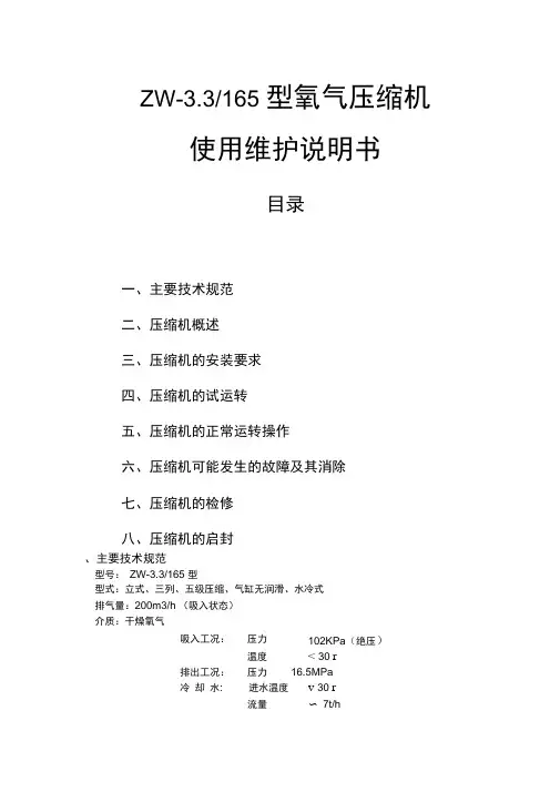
ZW-3.3/165 型氧气压缩机使用维护说明书目录一、主要技术规范二、压缩机概述三、压缩机的安装要求四、压缩机的试运转五、压缩机的正常运转操作六、压缩机可能发生的故障及其消除七、压缩机的检修八、压缩机的启封、主要技术规范型号:ZW-3.3/165 型型式:立式、三列、五级压缩、气缸无润滑、水冷式排气量:200m3/h (吸入状态)介质:干燥氧气吸入工况:压力102KPa(绝压)温度< 30 r排出工况:压力16.5MPa冷却水:进水温度v 30 r流量〜7t/h行程:180 mm转速:255r/min气缸直径:一级255m二级225m三级145m四级80m五级48m轴功率:52KW旋转方向:从飞轮端看为逆时针方向传动方向:电动机-- 三角皮带传动配用电机:型号Y208M-6功率55KW转速980r/min电压380V频率50Hz润滑油:规格L-AN68机械油(GB/T443-89)一次充灌量180L进气管径:①108X 4排气管径:①28 X 3 冷却水进水管管径:G3" 冷却水出水管管径:G4"机组总重量:〜5848Kg二、压缩机概述:本机主要由机身、曲轴、连杆、十字头、刮油器、齿轮油泵、气缸、活塞、气阀、冷却器、以及电动机等部件组成。
机身和曲轴箱沿曲轴中心线水平分开,并用圆锥销来定位,曲轴支承在四个滑动轴承上,曲轴轴衬由两半组成,安装在曲轴箱上,内有巴氏合金轴衬,上轴承盖压紧要轴承上,利用垫片可调节曲轴主轴颈与轴衬间的间隙。
曲轴箱上装有油面计,以观察箱内贮油量,后部有放油管,以排放旧润滑油。
机身前后有装卸孔,以便装卸十字头、连杆,拧紧连杆螺钉,十字头销及调整连杆轴承间隙,装卸孔上有盖板盖严。
曲轴的三个曲拐颈按120°等分,四个主轴颈作为支承点,并以一级与三级之间的中间轴承固定了曲轴的轴向移动,飞轮安装于曲轴的动力传递端以传递动力。
传动方式采用三角皮带传动,而主机的大皮带轮外圆设计为平面的,以与三角皮带的底面接触传动,其目的是减轻三角皮带的二侧面传动磨损,以延长三角皮带的使用寿命。
感谢您购买本产品,希望您成为本公司产品的满意用户。
本使用说明书叙述了产品的功能、操作步骤、注意事项、以及基本故障排除等内容。
为了保证您正确使用本产品,请务必在使用之前仔细阅读本使用说明书。
请注意本使用说明书中有些图例与您购买的产品可能不同,以实物为准。
▲重要提示:机器内部无尘过滤器,请根据使用情况及时更换。
车载型制氧机应严格按照其产品使用方法进行操作。
生产许可证编号:粤食药监械许20071409号注册证号:粤食药监械(准)字2010第2540273号为保障个人的安全和机器的性能在使用您的制氧机之前请通读本说明书。
一、安全须知◇本产品不能用于维持任何生命,建议患者在使用本产品时流量与吸氧时间的选择遵循医师的指导。
◇如果患者使用本产品时出现或表现出不良反应,请即与产品的供应商或医生联系。
◇重病患者在使用本产品时需另外配置指示设备和备用设备,如有不良反应请即告医生或联系产品供应商。
◇当不使用本产品时,应关闭电源开关。
◇氧气具有助燃作用,故本产品应远离明火和火源,在使用者附近严禁吸烟及明火;请勿将鼻管置于床罩或椅垫等物品之下,如无人吸氧空开机器时,所产生氧气会助然,产生安全隐患。
◇清拭本产品外壳灰尘之前,必须拔掉电源插头,以防触电。
◇不得随意拆卸维修本产品,如遇质量问题,发现报警等异常现象应与产品供应商或厂家联系。
二、注意◇本产品应置于干净无粉尘、无腐蚀、无毒害气体的环境使用。
◇本产品的空气入口应位于通风良好的空间,以避免氧气中含有空气污染或者烟雾。
◇本产品在使用时需保证底部排气畅通,否则会引起机器过热。
◇本产品在使用时有间歇的排气声(间隔时闻约5秒)。
◇从本产品启动到本产品性能稳定、出氧浓度稳定,需要3分钟的时间。
◇本产品作为医用供氧,输出气体在额定流量时,氧气浓度≥90%◇应使用随本产品所配的湿化瓶,不得随意更换,否则可能造成使用不适等危害。
◇本产品需清洁项目为湿化瓶(湿化瓶中的水应2-3天更换一次,同时清洗湿化瓶,夏季尤应连意。
Models 6-225, 6-425, 6-250, 6-450,6-275, 6-475, 6-650, and 6-850Air Hydraulic PressesWARNING LABELSTo the left is the safety Alert symbol. When you see these safety alert symbols on your press, Array be alert to the potential for personal injury.Follow recommended precautions and safe operating practices.SETTING UP THE PRESS FOR OPERATIONFor shipping convenience, some of the parts are not assembled. Assemble these parts in the following order:1. Bolt the base angles to uprights using four bolts and nuts, which are provided. Make sure baseangles are against stops on uprights.NOTE: The press should set on a level floor with the base angles touching the floor at allpoints. Use shims where necessary.2. Connect airline into street elbow (Item No. 136) at right hand side of control block.NOTE: Avoid restrictions in air supply line to insure ample air-to-air motor. To ensuremaximum performance the air supply line should be ½” pipe line if the distance from thecompressor to press is 0-30 feet, ¾” line 30-60 feet, and 1” if greater than 60 feet.NOTE: AIR MUST BE MOISTURE FREE. WATER IN AIR LINE WILL CORRODE THIS PRESSBEYOND REPAIR.3. Oil Requirements: Fill reservoir with Mobil DTE 24 or equivalent oil thru pipeline in back of press atpipe coupling by removing pipe plug. NOTE: Make sure the air-source is removed from thereservoir prior to removal of plug. Oil level may be checked (with ram up) by removing thepipe plug on the right side of reservoir near the front. Replace plug before operating the press.Model 6-225 & 6-425 25-ton presses use 6 quartsModel 6-250 & 6-450 50-ton presses use 8 quartsModel 6-275 & 6-475 75-ton presses use 10 quartsModel 6-650 & 6-850 150-ton presses use 20 quarts.4. Attach nose piece to ram by inserting shank into ram and tightening the set screw.5. CAUTION! Place the hoist crank on the lift drum shaft. Turn the hoist crank to relievethe pressure on the table pins. Keeping tension on the hoist crank, remove the table pins one at a time. After removing the tables pins, turn the crank running the table channels from top to bottom. Check to make sure the cable is tracking correctly. The cable should be on each ofthe two upper pulleys and should track back and forth on the cable drum. Always place tablepins under the table channels before releasing the hoist crank when positioning the tablechannels for cable tracking, servicing, or set-up for desired work opening. If a trackingproblem exists, contact the Dake factory for instructions. Be sure all table pins are fullyinserted in place before applying pressure. Always remove or release pressure on the cablebefore pressure is applied.Optional EquipmentRemote relief valve- part number 713510.OPERATIONSWARNING: DO NOT OVERSTROKE THE RAM. Overstroking will cause premature seal failure. Models 6-225, 6-425, 6-250, 6-275 and 6-475 have a 10-inch stroke. Models 6-650 and 6-850 have a 16-inch stroke.The press has been completely tested at the factory and after setting up according to instructions above, the press is ready for operation. However, it is necessary for the operator to acquaint themselves with the controls.1. Three screws (item 109) are used to lock the workhead in the desired position along headchannels.2. The handcrank (item 19) is provided to raise or lower the table channels to the proper work height.When desired height is obtained insert the table pins. Models 6-225, 6-425, 6-250 and 6-450 use 2pins on each side (4 total) and Models 6-275, 6-475, 6-650 and 6-850 use 3 pins on each side (6total). NOTE: Be sure ALL table pins are in place an in as far as they can go before pressureis applied. Be sure to slack off on the cable before pressure is applied. (Refer to point 5under SETTING UPS THE PRESS FOR OPERATION)3. The handle on the left side of the control block (item 76) opens and closes the ball valve, whichreleases pressure on the ram. This valve should be kept firmly closed and opened only when it isdesired to return the ram to its up position.4. The two table plates and two V-blocks are used for supporting the work in process.5. The control knob (item 103) on the right side of the panel regulates the speed of ram travel. Theknob will return to the off position when released.6. The relief valve (item 90) has been set at factory to open at maximum tonnage of press. The valvecan be adjusted by removing hex nut located on top of the valve block at the right front of reservoirand turning the adjusting screw to the left for a lower setting. WARNING: Never exceed ratedtonnage of press.MAINTENANCECAUTION: When disconnecting any parts of this machine be extremely careful that all parts are clean to prevent entrance of dirt in the hydraulic system.1. If press loses Pressure:a. Check all tubing joints for leaks and tighten the tube nuts.b. Leakage past release valve (Item 72). Drain the reservoir, and remove packing nut (Item75),valve rod (Item 73), and ball valve (Item 72). Clean out valve seat and reseat ball valve usingbrass rod as a drift striking sharply with a hammer. Reassemble valve rod, packing and packingnut. Refill reservoir with appropriate oil amount.c. Leakage past eductor inlet check ball (Item 69). Drain reservoir, remove large pipe plug (Item71), valve seat (Item 70), and check ball (Item 69). Clean and inspect seat. Reseat ball on seator replace seat with a new one if necessary. Reassemble with ball above the seat tighteningplugs securely.d. Worn cup leather (Serial No < 192522) or T-ring seal (Serial No > 192523). If none of theprevious conditions seem to have been the cause of the trouble, the cup leather or T-ring sealmay be worn out or damaged. To inspect this it is necessary to drain the oil and remove theworkhead from the press frame. Remove tube assembly (Item 144). Set 2 4x4 blocks on thetable then raise table channels with the block up to the bottom of the reservoir applying pressureto the reservoir. Remove roller brackets from the reservoir and lower workhead using the table.WARNING: Be sure that stroke indicator rod support (item 61) is installed in the side ofthe piston. If not, Insert ½”-13 stud or capscrew in tapped hole in piston. This will holdcylinder off piston. The piston leather or T-ring seal can now be inspected and replaced ifnecessary. Press may be reassembled in reverse order being careful not to damage the lip ofthe leather cup or T-ring seal as it enters the cylinder.2. If press will not develop rated tonnage.a. Dirt under valve balls. Refer to MAINTENANCE 1 – c above.b. Worn cup leather. Refer to MAINTENANCE 1 – d above.c. Relief valve not set properly. This valve is located on the top side near the right end of thecontrol block at the front of the reservoir. The valve is set at the factory to bypass oil from thepump back to the reservoir when the press reaches its rated capacity. The load on the spring(Item 91), which governs the pressure at which the valve will bypass oil, is adjusted by turningthe screw (Item 90) in to increase pressure or out to decrease pressure. Replace seal (Item89) and cap nut (Item 88). NOTE: We advise that the relief valve not be tampered withafter it is once set at the capacity of the press.3. If nothing happens when press is operated.a. Release valve open. Be sure to have release valve firmly closed when using press.b. If the ram will come down only a fraction of its rated stroke, check the oil level in the reservoirwith the ram at the top of its stroke. It should be visible in the sight window at the side of thereservoir.4. If press is operating slow.a. Check air supply line for restrictions to determine if air motors are getting ample supply of air.b. Release valve not closed properly. Release valve must be firmly closed when using the press.c. Wrong hydraulic fluid. After considerable research and tests made with the cooperation of thepump manufacturer, we recommend Mobil DTE 24 oil or equivalent.5. If Oil is coming out of the air vent.Drain out the spring chamber by removing the 1/8” pipe plug, which is put in the hub or boss that contains the oil seal where the ram extends out of the reservoir. Once oil is drained, run the press up to full tonnage with pipe plug still out. Excessive oil is a sign that the head seal has been damaged.Refer to Maintenance section 1 item d to replace seal. Replace pipe plug.6. Excessive leakage around the ram.Drain out the spring chamber as instructed in Maintenance section 5. A small amount of oil in this chamber facilitates lubricating the bushing the ram passes thru and prevents scoring. However, if operation performed on press is spoiled due to slight leakage of oil, remove pipe plug as described in MAINTENANCE 5 and connect tube line to continually drain this chamber.WARNING LABELSTo the left is the safety Alert symbol. When you see these safety alert symbols on your press, be alert to the potential for personal injury.Follow recommended precautions and safe operating practices.Carefully read all safety messages in these instructions and on your press safety signs.Keep safety labels in good condition. Replace missing or damaged safety labels. This machine is intended to be operated by one person. This person should be conscious of the press ram movement not only forLabel 300168 Label 84487Label 84399Label Placement ViewLabel 84395 Label 76462Label 7355Control Block Exploded ViewGrand Haven, MI 49417Phone: 616-842-7110 800-937-3253Fax: 616-842-0859 800-846-3253Web: E-mail: *********************************************************Ite m Part NameModel6-2256-425Model6-2506-450Model6-2756-475Model6-6506-850Qty1 Pulley 602-25H 602 727 1563 22 Frame 700134 700116 706943 701030 13 Hex head cap screw 43341 43342 43361 43720 24 Name plate 81002 81002 81002 81003 15 6-32 x ½” Self tapping screw 43876 43876 43876 43876 46 Table plate 966 545 702 1534 27 V-block - 336 336 1576 28 Table spacer assembly 716691 716692 716788 1553 49 Table channel 701020 701091 706945 701032 210 Lockwasher 43647 43647 43648 43649 811 Hex nut 43916 43916 43917 43919 812 Table pins 981 569 - - 4Table pins - - 569 7205 6 Safety clips 302816 613 Base angle 978 566 566 1551 214 Hex cap screw 43349 43349 43349 43365 415 Lockwasher 43647 43647 43647 43648 416 Square nut 43916 43916 43916 43917 417 Cable 988 580 726 1562 118 Cable clamp 991 991 991 583 419 Hoist crank assembly 701653 701653 701653 701653 120 Worm shaft 7530 7530 7530 742 1 21A Retaining ring 43978 43978 43978 43982 2 21B Retaining ring 27437 27437 27437 43983 222 Worm key 386 386 386 746 123 Worm 385 385 385 744 124 Hoist frame 725 725 725 739 125 Hex cap screw 43335 43335 43335 43353 226 Hex nut 43912 43912 43912 43916 227 Drum shaft 724 724 724 741 128 Drum key 737 737 737 745 129 Worm gear 736 736 736 743 130 Cable drum 723 723 723 740 1 Complete Table Hoist Assembly(Items 20, 21A, 21B, 22, 23, 24, 27, 28, 29,30)701677-S 701677-S 701677-S 700111-S 1Figure 237 ½” Hex Nut 43916 43916 43916 43916 6 39 Cylinder Gasket 9776 9777 9777 9778 140 ½”-13 x 1-½” Soc. Hd. Cap Screw(Serial No. < 192522) -- 43471 43471 -- 141 Piston Bumper (Serial No. < 192522)-- 2221 2221 -- 142 ¼”-20x1” HHCS (Serial No. < 192522)43305 -- -- -- 43/8”-16x1-¼” HHCS (Serial No. < 192522)-- 43330 -- -- 6 3/8”-16x1-¾” HHCS (Serial No. < 192522)-- -- 43332 43332 8 43 ¼” Lockwasher (Serial No. < 192522)43643 -- -- -- 43/8” Lockwasher (Serial No. < 192522)-- 43645 43645 43645 6-844 Supporting Ring (Serial No. < 192522)967 4110 2222 1536 145 Leather Cup (Serial No. < 192522)969 557 706 1538 1T-ring Seal (Serial No. > 192523)17976 17878 17942 37052 146 Cylinder 7361 4101 2213 4197 147 Piston Assembly (Serial No. < 192522)701401 701402 701403 701404 1Piston Assembly (Serial No. > 192523)716225 716226 716227 716228 1 48 Ram Spring (Small) 5722 4107 2231 4196 1Figure 150 Ram Spring (Large) 5721 4106 2232 4195 1Ite m Part NameModel6-2256-425Model6-2506-450Model6-2756-475Model6-6506-850Qty51 Piston Bushing (Serial No. < 192522)5731 4111 2229 1158 1Wear Ring (Serial No. > 192522)76805 76806 76807 3704552 Oil Seal 6019 6020 6021 1477 153 Oil Seal Gasket 6516 6517 6518 6519 154 Retaining Plate 7359 6513 6514 6474 155 No. 10-24 x ½“ Rd. Hd. Screw 43881 43881 43881 43881 4-656 5/16” Set Screw 43575 43575 43575 43575 157 Nose Piece Assembly 701706 701707 701708 701709 158 V-Nose Assembly 701710 701711 701712 701713 159 Stroke Indicator Rod 2260 2260 2260 4264 160 ½“-13 Hex Jam Nut 43940 43940 43940 43940 161 Special Nut 2259 2259 2259 2259 162 ¼“-20 x ¼” Soc. Hd. Set Screw 43558 43558 43558 43558 163 Support Stud 2258 2258 2258 4266 164 No. 2 x 3/16” Drive Screw 43616 43616 43616 43616 365 Scale 2261 2261 2261 4265 166 Reservoir Assembly 715266 716784 716784 715269 167 1/8” N.P.T.F. Soc. Hd. Pipe Plug 589 589 589 589 268 Check Valve Seat 1300 1300 1300 1300 269 ½” N.P.T.F. Soc Hd. Pipe Plug 596 596 596 596 370 3/8” N.P.T.F. Soc Hd. Pipe Plug 588 588 588 588 571 ¼” N.P.T.F. Soc. Hd. Pipe Plug 1567 1567 1567 1567 172 Ball Valve ¾“ Dia. 1936 1936 1936 1936 173 Release Valve Rod 2257 2257 2257 2257 174 Valve Rod Packing 1937 1937 1937 1937 775 Packing Nut 1931 1931 1931 1931 176 Valve Handle 2230A 2230A 2230A 2230A 177 Handle Washer 348 348 348 348 178 3/8”-16 x ¾“ Hex Cap Screw 43326 43326 43326 43326 179 Plunger Unit 6151 6151 6151 6151 180 Pivot Pin 6152 6152 6152 6152 181 Air Control Arm 6153 6153 6153 6153 182 Air Control Link 6154 6154 6154 6154 185 Air Control Shaft 6156 6156 6156 6156 186 Pin 5772 5772 5772 5772 387 1/16” x ½” Cotter Pin 44049 44049 44049 44049 688 Valve Cap Nut 2236 2236 2236 2236 189 O-ring 3965 3965 3965 3965 190 Relief Valve Adj, Screw 2237 2237 2237 2237 191 Relief Valve Spring 893 893 893 893 192 Ball Retainer 892 892 892 892 193 Ball Valve ¼” Dia. 918 918 918 918 194 Relief Valve Seat 891 891 891 891 195 Check Valve Spring 579 579 579 579 196 Check Valve Spring 890 890 890 890 197 Ball Valve ½” Dia. 586 586 586 586 2 100 No. 10-24 x 2-¾” Machine Screw 300248 300248 300248 300248 4 101 Gauge 71270 71271 71272 71273 1103 Control Knob 2250A 2250A 2250A 2250A 1Ite m Part NameModel6-2256-425Model6-2506-450Model6-2756-475Model6-6506-850Qty104 ¼”-20 x ½” Soc. Hd. Set Screw 43562 43562 43562 43562 1 105 ½” Washer 43634 43634 43634 43634 1 106 5/8”-11 Hex Nut 43917 43917 43917 43917 7 108 Rear Roller Bracket 9472 9472 9472 4204 1 109 ¾”-10 x 3” Set Screw 43616 43616 43616 43616 3 112 Flanged Roller 2244 2244 2244 2244 3 113 Bearing 6023 6023 6023 6023 3 114 Front Roller Bracket 9473 9473 9473 4205 1 115 Pump – Haskel Air 63453 63453 63453 63453 1 116 3/8” Pipe Nipple 58226 58226 58226 58226 1 123 ¾” x 4” Pipe Nipple 1818 1818 1818 1818 1 124 ¾“ 90° Pipe Elbow 74017 74017 74017 74017 1 125 ¾“ x 2” Pipe Nipple 58227 58227 58227 58227 1 126 ¾“ Pipe Coupling 1744 1744 1744 1744 1 128 3/8” Street Elbow 1264 1264 1264 1264 2 129 3/8” Pipe Nipple 58226 58226 58226 58226 1 130 Quick Exhaust 1911 1911 1911 1911 1 132 Restrictor 7368 7368 7368 7368 1 133 3/8” Pipe Nipple 58226 58226 58226 58226 1 134 ¼“ - 1/8” Bushing 1100 1100 1100 1102 3 136 ¼“ 90° Street Elbow 1110 1110 1110 1110 1 137 ¼“ Pipe Coupling 1330 1330 1330 1330 1 138 Check Valve 1841 1841 1841 1841 1 139 Tube Fitting 19576 19576 19576 19576 5 140 Air Vent 632 632 632 632 1 141 Tube 7680 7681 7682 7683 1 142 Tube 7684 7684 7684 7685 1 143 Tube Elbow 1944 1944 1944 1944 2 144 Tube Assembly 701719 701720 701721 701722 1 145 Tube Elbow 1252 1252 1252 1252 2 146 Tube Assembly 701723 701723 701723 701724 1 147 Tube Elbow 1248 1248 1248 1248 2 148 Tube Assembly 701725 701725 701725 701726 1 Cylinder Repair Kit (Items: 39, 45, 52, 53, 72,74, 89, 93, 97)713053 713054 713055 713056 1 Haskel Pump Repair Kit 713034 713034 713034 713034 1-2 ADDED PARTS USED WITH DOUBLE PUMP PRESSES NOT ILLUSTRATED115 Pump 63453 63453 63453 63453 1 139 Tube Fitting 597 597 597 597 5 149 Tube Tee 1249 1249 1249 1249 1 150 Tube Tee 7693 7693 7693 7693 1 151 Tube Assembly 701727 701727 701727 701728 1 152 Straight Fitting 1251 1251 1251 1251 1 153 Tube Assembly 701729 701729 701729 701729 1 154 Straight Fitting 1247 1247 1247 1247 1 155 Tube Assembly 701730 701730 701730 701731 1Model 6-225, 6-425, 6-250, 6-450,11 6-275, 6-475, 6-650, & 6-850。
氧压机操作规程
一、一、开机前的检查及准备工作
1、检查各阀门(循环水进出水阀、放空阀、仪表根阀等)是
否处于正确的开关位置
2、检查各仪表是否完整无缺,查看油室油位是否在规定的位
置
3、查看各连接螺栓是否有松动,盘车数周,以确定氧压机活
塞无卡涩等异常状况
二、开机步骤
1、打开氧压机放空阀和进气口阀,打开氧压机循环水进出水阀
2、按下控制柜上的启动按钮,此时启动灯亮,空压机启动
3、注意观察风机的运行状况,是否有杂音及异味等不正常情况
4、查看氧压机油压是否介于0.1MPa-0.3MPa之间
5、待氧压机运转正常后,打开氧压机出口阀,关闭氧压机放空阀,调节压力至所需压力,此时查看氧压机一级出口压力是否在
0.15-0.21MPa之间
三、停机步骤
1、打开氧压机放空阀,关闭氧压机出口阀
2、按下控制柜上的停机按钮
3、关闭氧压机循环水进出水阀门
4、通过氧压机上的循环水导淋阀放尽各冷却器内的水
三、注意事项
1、机器油室油位应处于规定的位置(2\1-3\2)
2、循环水压力不低于0.2MPa,不高于0.3MPa
3、通过循环水压力表,观察并确定各冷却器循环水运行正常
4、氧压机后冷却器要经常从底部导淋阀放水,以防止把水带到预冷机内
5、在机器运转时,不要在机器周围动火,也不要让润滑油等有机溶剂洒落在机器周围
6、机器在运行以前,进气管路一定要保证干净无机械杂质,以防铁锈等杂质进入到气缸内引起爆炸事故
7、在长时间停机时,氧压机气缸内要用氮气置换保护。
制氧机使用说明书制氧机使用说明书篇一:家用制氧机的使用方法家用制氧机的使用方法鱼跃制氧机适用:医疗机构和家庭进行氧疗与保健。
1、医疗功能:给患者供氧,配合治疗心脑血管、呼吸系统、。
慢性阻塞性肺炎等疾病,以及煤气中毒及其它严重缺氧病症。
2、保健功能:通过给氧改善身体供氧状况,达到补氧保健的目的。
适用于中老年人,体质较差者,孕期妇女,高考学生等存在不同程度缺氧的人群,也可在重体力或脑力消耗后,用于消除疲劳,恢复身体机能。
3、鱼跃制氧机适用于城市、乡村、边远地区、山区、高原等中小型医院、诊所、卫生站等。
同时也适用于疗养院、家庭氧疗、体育训练中心、高原兵站及其他用氧场所。
何谓氧中毒?长时间、高流量吸氧(指吸入浓度为90%以上氧气,流量>5升/分),从而导致肺泡中氧浓度过高,使得肺泡及人体出现各种损害性病变,称为氧中毒。
如果吸入90%以上的氧气流量控制在1—3升/分钟之间,则肺泡氧浓度在25-33%之间,符合肺泡中气体交换的最佳浓度,是绝不会发生氧中毒的。
1、氧流量不宜过高或过低,过高会造成二氧化碳在体内潴留,加重病情;过低则达不到氧疗效果,正确的吸氧流量应该2升/分钟左右,(90%以上医用氧)。
2、根据病情状况,确定每天氧疗时间:(1)慢性阻塞性肺疾病(慢性支气管炎、支气管哮喘、肺气肿、肺心病等)每天氧疗时间最好在15小时以上,具体时段不限;(2)心脑血管系统疾病(高血压、高血脂、动脉硬化、冠心病、心律失常、脑血栓、脑萎缩等)、颈椎病患者建议每天分早晨、下午、晚上三次吸氧,每次吸氧40分钟左右;(3)糖尿病人建议每日吸氧2-4次,每次1小时左右,分别安排在早上、上午、下午、晚上;(4)失眠患者最好在临睡前吸氧30-60分钟;(5)亚健康状态、美容每次吸氧在30分钟左右,一天1-2次;制氧机使用说明书篇二:制氧机说明书变压吸附制氧机操作使用说明书JIUDA深圳市久大轻工机械SHEN ZHEN JIUDA LIGHT INDUSTRY MACHINERY CO. LTD.目录1、相关知识31.1. 气体知识31.2. 压力知识31.3. 电力知识31.4. 安全知识31.5. 知识产权31.6. 提示32、变压吸附(PSA)制氧原理及系统设备概述42.1. 概述42.2. PSA制氧原理42.3. PSA制氧基本工艺流程42.4. PSA制氧系统设备53、设备安装及工况条件6 3.1. 设备布置要求63.2. 工况条件73.3. 设备安装74、设备调试及开停车7 4.1. 设备调试前准备工作7 4.2. 设备首次开车74.3. 设备正常开车步骤8 4.4. 设备正常停车步骤84.5. 故障紧急停车步骤84.6. 设备正常运行状态描述94.7. 设备操作注意事项95、设备检验95.1. 检验标准95.2. 设备出厂检验96、设备维护106.1. 设备日常维护106.2. 设备周期性维护106.3. 常见故障处理116.4. 设备维护记录表117、随机附件117.1. 设备清单117.2. 随机提供的资料、备件127.3. 设备提示、警示牌128、设备保修条款128.1. 设备质量保证条款12 8.2. 设备保修范围128.3. 产品售后服务承诺13 附件1.系统日常工作记录表附件2.系统维护记录表1、相关知识1.1. 气体知识氧气作为空气中含量丰富的气体,取之不竭,用之不尽。
Pressure Booster SystemPlease read and save these instructions. Read carefully before attempting to assemble, install, operate or maintain the product described. Protect yourself and others by observing all safety information. Failure to comply with instructions could result in personal injury and/or property damage! Retain instructions for future reference.REMINDER: Keep your dated proof of purchase for warranty purposes! Attach it to this manual or file it for safekeeping.Figure 1DescriptionThe booster is designed to increase water pressure from municipal sources or private water systems. The unit is equipped with a 1/2 HP , 120 volt single-phase motor. Use only to pump clear water. The system includes the pump, control box, pressure sensing switch, bladder tank, and flow sensing switch.Do notattempt touse product at 240 volt. Only 120 volt is allowed.UNPAcKINgAfter unpacking the pressure booster sys-tem, carefully inspect for any damage that may have occurred during transit. Check for loose, missing or damaged parts.Safety guidelinesThis manual contains information that is very important to know and understand. This information is provided for SAFETY and to PREVENT EQUIPMENT PROBLEMS. To help recognize this information, observe the following symbols.Danger indicatesan imminently hazardous situationwhich, if not avoided, will result in death or serious injury.Warning indicatesa potentially hazardous situation which, if not avoided, could result in death or serious injury.Caution indicatesa potentially hazardous situation which, if not avoided, may result in minor or moderate injury.Notice indicatesimportant information, that if not fol-lowed, may cause damage to equipment.general Safety InformationThisor its power cord may contain chemicals known to the State of California to cause cancer and birth defects or other repro-ductive harm. Wash hands after handling.gENERAl SAFEty1. Read these rules and instructionscarefully. Failure to follow theseinstructions could cause serious bodily injury and/or property damage.2. Know the pump application,limitations and potential hazards.Always install apressure relief valve to match the system pressure rating and the maximum flow rate.Do not use topump flammable or explosive fluids such as gasoline, fuel oil, kerosene, etc. Do not use in explosive atmospheres. Pump should only be used with liquids compatible with pump componentmaterials. Failure to follow this warning can result in personal injury and/or property damage. Disconnect powerand release all pressure from the system before attempting to install, service, relocate or perform any maintenance. Lock the power disconnect in the open position. Tag the power disconnect to prevent unexpected application of power.3. Drain all liquids from the systembefore servicing.4. Secure the discharge line beforestarting the pump. An unsecured discharge line will whip and possibly cause personal injury and/or property damage.5. Periodically inspect pump andsystem components. Perform routine maintenance as required (See Maintenance).6. PERSoNAl SAFEty:a. Wear safety glasses at all timeswhen working with pumps.b. Keep work area clean,uncluttered and properlylighted. Replace all unused tools and equipment.c. Keep visitors at a safe distancefrom work area.d. Make the workshop childproofuse padlocks, master switches and remove starter keys.7. Do not pump chemicals or corrosiveliquids. Pumping these liquidsshortens the life of the pumps seals and moving parts and will void the warranty.8. Complete pump and piping systemMUST be protected against below freezing temperature. Freezing temperatures could cause severe damage and void the warranty.9. Do not run the pump dry or damagewill occur and will void warranty.Risk ofelectricalshock. This pump is designed for indoorinstallation only.All wiringshouldbe performed by a licensed or certifiedelectrician.10. For safety, the unit must beconnected to a grounded circuitequipped with a ground faultinterrupter device.11. Before installing the pump, havethe electrical outlet checked by alicensed or certified electrician tomake sure the outlet is properlygrounded.12. Make sure the line voltage andfrequency of electrical currentsupply agrees with the motorwiring.Do notattempt touse product at 240 volt. Only 120 volt isallowed.13. Do not attempt repairs to theelectric motor. All repairs to themotor must be completed at alicensed or certified electrical motorrepair shop.Do nottouchan operating motor. Modern motorsare designed to operate at hightemperatures.14. Avoid kinking electrical cord andprotect from sharp objects, hotsurfaces, oil and chemicals. Replaceor repair damaged or worn cordsimmediately.Disconnect power and release allpressure from the system beforeattempting to install, service, relocateor perform any maintenance. Lock thepower disconnect in the open position.Tag the power disconnect to preventunexpected application of power.15. Keep fingers and foreign objectsaway from ventilation and otheropenings. Do not insert any objectsinto the motor.general SafetyInformation(continued)Risk ofelectricshock! Never connect the green (or greenand yellow wire) to a live terminal!16. To reduce the risk of electricalshock, the pump should be pluggeddirectly into a properly installedand grounded 3-prong groundingtype receptacle, as shown inFigure 2. The green (or green andyellow) conductor in the cord is thegrounding wire. The motor must besecurely and adequately groundedfor protection against shock.17. Where a 2-prong is encountered,replace the plug with a properlygrounded 3-prong receptacle inaccordance with the NationalElectrical Code, local codes andordinances. To ensure a properground, the grounding means mustbe tested by a licensed or certifiedelectrician.Do nothandlepump or pump motor with wet hands,when standing on a wet or dampsurface or when standing in water. Fatalelectrical shock could occur.Pumpmotor isequipped with an automatic resettingthermal protector and may restartunexpectedly. Protector tripping is anindication of motor overloading becauseof operating pump at low heads (lowdischarge restriction), excessively highor low voltage, inadequate wiring,incorrect motor connections or defectivemotor or pump.InstallationlocAtIoNSelect a location as close to the watersupply as possible. Be sure to complywith any state or local codes regardingthe placement of the pump. Theequipment must be protected from theelements. A basement or heated pumphouse is a good location. Make surethe pump has proper ventilation. Thetemperature surrounding the pump isnot to exceed 100°F (40°C) or nuisancetripping of the motor overload mayoccur.PIPINgPiping may be copper, steel, rigid PVCplastic or flexible polyethylene plastic.Flexiblepipe isnot recommended on suction pipe (inletpipe). Flow sensor is designed for 1” NPTconnection.The pipe must be clean and free of rustor scale. Use a pipe joint compoundon the male threads of the metal pipe.Teflon® tape should be used with plasticthreads. All connections must be airtight to insure normal operation.Slope all inlet piping upwards towardsthe pump to prevent trapping air.IMPoRtANt: Pump is built to handleclear water only; it is not designed tohandle water containing sand, silt orother abrasives.1. Refer to FIgure 3 for typicalinstallations.2. Bolt pressure booster system to asecure foundation.3. Locate the pump so that there willalways be a positive supply of waterto the pump (See Figure 3).4. For service convenience, the installeris recommended to add gate valvesand unions as needed to provide foreasier maintenance.5. Pressure gauges on the inlet andoutlet, provided by the installer, arerecommended to show if sufficientwater is being supplied to the pumpand to show service pressure.shock. This pump is designed for indoor installation only.Disconnect power and release all pressure from the system beforeattempting to install, service, relocate or perform any maintenance.IMPoRtANt: Do not use an extension cord or splice wires. Joints should bemade in an approved junction box. If the above information is confusing, consult a licensed electrician.Your unit is supplied with a pressure switch, flow sensor and a control box. The only wire connection needed is to plug the two red wires from the control box into the two red wires on the flow sensor (See Figure 3).Figure 3 - typical installationMotoR PRotEctIoNThis motor has built in thermalprotection. The overload protects the motor against burnout from overload of low voltage, high voltage and other causes. The device is automatic and resets itself once the temperature has dropped to a safe point. Frequenttripping of the device indicates trouble in the motor or power lines andimmediate attention is needed.Never examine,make wiring changes or touch the motor before disconnecting the main electrical supply switch. The thermal device may have opened the electrical circuit. The pump motor should be equipped with a correctly fused disconnect switch to provide protection. Consult local or United States National Electrical Codesfor proper fuse protection.fluid before operating. Do not run dry or against a closed discharge. Do not pump dirty water or abrasive liquids. To do so will cause the pump failure and will void the warranty.VAlVESThe inlet and outlet isolation valves should be in the full open position.PRIMINgNotE: Before starting the pump it is absolutely necessary that both the pump and the inlet pipe be completely filled with water.PRESSURE BooSt INStAllAtIoNS Priming is automatic when pump isconnected to a pressure source such as a hydrant or city main. (See Figure 3).1. Open valves or nozzle on inlet anddischarge side of pump.2. Open a faucet nearest the boosterunit. Plug pump into outlet. When the water flow from the faucet reaches one gallon per minute, or greater, the pump will automatically start. Keep the faucet open forapproximately 30 seconds to relieve trapped air in the line. When the faucet is closed, the pump willcontinue to run until pressure reaches 60 psi.Thepressureswitch is factory set at 50 psi and must not be changed. 3. If you installed a pressure gauge atthe pump inlet, a reading of 2 psi minimum should show whenever the pump is in operation. This read-ing ensures that there is an ample supply of water into the pump inlet housing.4. The controller, flow sensor andpressure switch continuouslymonitor water pressure and flow. The system automatically turns the unit off if pressure reaches 50 to 53 psi. The control package also protects the unit from dry run by shutting down if water usage drops below 1 gallon per minute.MotoR/PUMP RotAtIoN1. The motor rotates in a counterclockwise rotation when facing the pump end and cannot be reversed.StARt -UP PRocEDUREOnce the preceding instructions have been completed, the unit is ready for normal operation.1. During the first few hours ofoperation, inspect the pump, piping and any auxiliary equipment used in connection with the unit forleaks, excessive vibration or unusual noises.2. The booster unit will turn on andoff automatically, based on water usage.and release all pressure from the system before attempting to install, service, relocate or perform any maintenance. Lock the power disconnect in the open position. Tag the power disconnectto prevent unexpected application of power.Protect the pumpfrom freezing during winter conditions.DRAININg thE PUMPDrain openings are provided on all models. To drain the pump:1. Remove drain plug and prime plugto vent the system.operation(continued)REMoVINg olD ShAFt SEAlTurndisconnectswitch to “off” position.1. Open a faucet nearest the tank andallow all water to drain from the tank.2. Remove the four cap screws holdingthe pump housing (volute) to the motor (Figure 4).3. Separate the pump housing (volute)from the motor to expose the diffuser and the seal plate.4. Remove the two cap screws anddiffuser from the seal plate to expose the impeller.5. Remove the small end cap on theend of the motor opposite the impeller.6. With a large screwdriver oradjustable wrench, keep the shaft from rotating and remove the impeller by hand (standard right hand thread). Be sure to hold onto the seal plate when removing the impeller from the shaft.7. Remove the seal plate.8. Pry the rotating shaft seal memberfrom the impeller (Figure 5).9. Push or pry the ceramic seat freefrom the seal plate (Figure 5).10. Remove loose particles fromimpeller hub and seal plate.INStAllINg NEW ShAFt SEAlBefore handlingshaft seal parts wipe hands clean. Dirt or grease can damage the seal.1. Wet the inside of the seal cavityon seal plate and the rubber cup enclosing the new ceramic seat with cooking oil. Be careful not to scratch the ceramic surface of the seal seat and push seat enclosed in rubber into seal cavity on seal plate. Use a cardboard washer to protect polished surface when pushing against ceramic seat with anyobject. Be sure to remove cardboard washer.2. Carefully slip seal plate over shaft.Do not disturb seal position in seal plate. The seal plate must be orientated during assembly so the two screw holes are on a horizontal line across the motor shaft and the (4) locating pins on the back of the seal plate line up with the tabs on the motor housing (Figure 6). This placement should be done to ensure proper draining and priming.3. Place rotating shaft seal member inposition on impeller and press into place. Take care not to press against polished seal surface.4. Position impeller on shaft andtighten securely (Figure 7).5. Secure diffuser to seal plateusing the two cap screws. Be sure the screws are orientated on ahorizontal line as described in Step 2.Figure 4Seal PlateDiffuserCap ScrewsPump Housing (Volute)Figure 5 - Removing Shaft Seal and ceramic SeatPlateRubber Seat RingCeramic SeatShaft Seal MemberImpellerFigure 6 - Seal Plate Replacement6. Carefully position pump housing(volute) gasket over the diffuser onto the seal plate. In all shallow well applications care must be taken that the o-ring is clean and properly positioned on the venturi. Cleaning and positioning makes a good seal inside the diffuser when assembled.7. Assemble the pump housing (volute)to the motor using the four cap screws. Be sure the pump housing (volute) gasket is positioned correctly and tighten the screws securely.NotE: Shaft must rotate freely andmotor end cap should be secured before operation.Figure 7 - Motor ShaftMotorImpellerSeal Facing Must BeClean for Proper SealTroubleshooting ChartELECTRICAL PRECAUTIONS - Before servicing a pump, always shut off the main power breaker and then unplug the pump. Make sure you are not standing in water and are wearing insulated protec-tive sole shoes. Under flooded conditions, contact your local electric company or qualified licensed electrician for disconnecting electrical service prior to pump removal.SymptomPossible Cause(s)Corrective ActionPump won’t start or run at full speed1. Blown fuse or open circuit breaker 1. Replace fuse or close circuit breaker. See wire chart for proper breaker/fuse size2. AC power is OFF 2. Turn power on3. Incorrect voltage3. Low voltagea. Voltage must be within ± 10% of motor rated voltage. Check incoming voltage. Contact power companyb. Motor voltage is set for 120V AC. System is not designed for 240V service .4. Defective motor4. Replace motor5. Pump internal components clogged/worn/ damaged5. Replace worn parts or entire pump. Clean parts if requiredContinued on next pagePump operates, but delivers little or no water 1. Valves plumbed into system restrictingflow1. a. Check valves on pump inlet and discharge sidesof system. Be certain they are opened com-pletely to allow flow to and from the pump.b. Bleed trapped air in pump. (Normally due toclosed valve in discharge plumbing).2. In-line filter restricting flow 2. Check all in-line filters to be sure they are notplugged or restricted3. Low line voltage 3. See low line voltage corrective action (above)4. Inadequate water supply to boosterpump4. Check pressure on inlet side of booster to be surepositive pressure is maintained to the boosterpump at all times5. Undersized piping 5. Replace undersized piping6. Leak on inlet side of system 6. Make sure connections are tight. Repair leaks asneeded7. Worn or defective pump parts or pump7. Replace worn parts or entire plugged impeller.Clean parts if required8. Suction lift to great8. Pump should be operated under flooded suctiononly. See Corrective Action 4 above.9. Pump not primed9. Prime pump. Make certain inlet pipe connectionsare tight and pump and pipe are full of waterExcessive noise whilepumping1. Pump not secured to firm foundation 1. Secure properly2. Piping not supported 2. Make adjustments3. Restricted inlet line 3. Clean, correct, or eliminate retrictions4. Cavitation (pumping marbles) 4. Increase inlet pipe size5. Worn motor bearings 5. Replace motorPump leaks 1. Worn mechanical seal (leaks at shaft) 1. Replace shaft (rotary) seal2. Damaged o-ring seals 2. Replace square ring rubber gasketFor Replacement Parts, call 1-800-237-0987Please provide following information: Address parts correspondence to:- Model number Wayne Water Systems- Serial number (if any) 101 Production Drive- Part description and number as shown in parts list Harrison, OH 45030 U.S.A.1Motor32059-0011 2Screw16636-0023Seal plate17145-0011 4•Square ring rubber gasket17150-0011 5•Shaft seal assembly563931 6Impeller23285-0021 7Diffuser17148-0011 8Screw67007-0019•O-ring155571 10Venturi17151-0021 11Nozzle156721 12Pipe plug 3/4”159211 13Volute56869-0011 14Pipe plug 1/4” NPT16314-0021 15Pipe plug 1/8” NPT15766-0021 16Base23029-0011 17Flow switch30048-0011•Repair kit (Includes #4, 5 and 9)56874-0011lIMItED WARRANtyFor one year from the date of purchase, Wayne Water Systems (“Wayne”) will repair or replace, at its option, for the original purchaser any part or parts of its Sump Pumps or Water Pumps (“Product”) found upon examination by Wayne to be defective in materials or workmanship. Please call Wayne (800-237-0987) for instructions or see your dealer. Be prepared to provide the model and serial number when exercising this warranty. All transportation charges on Products or parts submitted for repair or replacement must be paid by purchaser.This Limited Warranty does not cover Products which have been damaged as a result of accident, abuse, misuse, neglect, improper installation, improper maintenance, or failure to operate in accordance with Wayne’s written instructions.thERE IS No othER EXPRESS WARRANty. IMPlIED WARRANtIES, INclUDINg thoSE oF MERchANtABIlIty AND FItNESS FoR A PARtIcUlAR PURPoSE, ARE lIMItED to oNE yEAR FRoM thE DAtE oF PURchASE.thIS IS thE EXclUSIVE REMEDy AND ANy lIABIlIty FoR ANy AND All INDIREct oR coNSEQUENtIAl DAMAgES oR EXPENSES WhAtSoEVER IS EXclUDED.Some states do not allow limitations on how long an implied warranty lasts, or do not allow the exclusions or limitations of incidental or consequential damages, so the above limitations might not apply to you. This limited warranty gives you specific legal rights, and you may also have other legal rights which vary from state to state.In no event, whether as a result of breach of contract warranty, tort (including negligence) or otherwise, shall Wayne or its suppliers be liable for any special, consequential, incidental or penal damages including, but not limited to loss of profit or revenues, loss of use of the products or any associated equipment, damage to associated equipment, cost of capital, cost of substitute products, facilities, services or replacement power, downtime costs, or claims of buyer’s customers for such damages.You MUSt retain your purchase receipt along with this form. In the event you need to exercise a warranty claim, you MUSt send a copy of the purchase receipt along with the material or correspondence. Please call Wayne (800-237-0987) for return authorization and instructions.Do Not MAIl thIS FoRM to WAyNE. Use this form only to maintain your records.MODEL NO. __________________ SERIAL NO. _____________________ INSTALLATION DATE _________________ AttAch yoUR REcEIPt hERE。
ZW - 84/ 30 型氧气压缩机使用说明书YY5201 SM开封黄河空分集团有限公司二〇〇八年元月目次1概述------------------------------------------------------------------------------------------ 32主要性能参数------------------------------------------------------------------------------ 3 3各系统说明--------------------------------------------------------------------------------- 4 4主机主要部件和机组辅助设备说明--------------------------------------------------- 5 5压缩机的主要装配间隙表--------------------------------------------------------------- 8 6压缩机正常开车时的运转参数表------------------------------------------------------ 8 7压缩机主要零部件、备件和专用工具清单------------------------------------------ 9说明本机的安装、调试、使用与维护等应仔细阅读HHSJ《活塞压缩机使用说明书》和YY5201 SM 本机说明书。
注意本氧压机气路部分严格禁油!!!1概述ZW - 84/30 型氧气压缩机为立式、四级四列、双作用、水冷却、无润滑、活塞式氧气压缩机。
可用于大中型空分设备和石油化工等其它工业部门。
该机主要特点为 :a.结构紧凑、占地面积小、重量轻。
b.动力平衡性好、运转平稳可靠。
c.振动和噪音小。
d.运转经济性好。
e.导向环、活塞环、填料磨损均匀、寿命长。
f.外形美观。
2主要参数型式立式、三级四列、无润滑、活塞式介质氧气(φ=0)标准状态5200m3/ h排气量吸入状态84m3/ min进气压力0.015MPa排气压力 3.0MPa进气温度25℃压排气温度≤40℃轴功率850kW转速494r/ min行程240mm缩一级Φ 550×2缸径二级Φ 430三级Φ 260名义活塞力120kN机润滑油牌号68#L - TSA汽轮机油润滑油一次充填量400L冷却水进水温度≤32℃冷却水总耗量120t/ h主机重量16500 kg机组总重量35000 kgcm)主机外形尺寸320×132×325 (cm cm××机组占地面积(长×宽)8m×6m电型号Y630- 12 型异步电动机动功率900kW机电压10kV3各系统说明请参阅YY5201 LC 流程图。
3.1气体系统低压氧气,经吸入滤清器过滤,再经各级压缩及冷却后,送往各使用单位。
具体走向如下 :吸入滤清器→一级缓冲器→一级气缸压缩→一级缓冲器→一级冷却器→二级缓冲器→二级气缸压缩→二级缓冲器→二级冷却器→三级进气缓冲器→三级气缸压缩→三级排气缓冲器→三级冷却器→使用单位。
一级进口设有进气蝶阀和试车进气蝶阀,三级冷却器后设有排气截止阀及放空阀,放空阀为气体紧急放空、吹除及试车用。
3.2冷却系统通往一台压缩机组(主机和各冷却器)的冷却水来自一根DN150 上水总管。
然后由进水总管分六条支管分别接各级气缸和各冷却器进水口。
其中 DN40 支管一条,接到油冷却器进水口; DN32 支管二条,分别接到一级气缸和二、三级气缸进水口; DN65 支管三条,分别接到各冷却器进水口。
各排水管管径分别与各自对应的进水管管径相同,各排水管上均设有测温装置,各进水管和各排水管用的地沟均由用户根据需要和现场位置自行设计,冷却水管全部采用钢管。
冷却水的水质要求:项目名称单位要求上水压力MPa0.35~0.45回水压力MPa0.15~0.20酸碱度pH 值7~8悬浮物含量mg/L≤ 100总硬度mmol/L≤3.2 (18 德国度 )水垢系数m2K/W0.00026~0.00043冷却水管路由用户自理。
3.3润滑油系统由于导向环、活塞环和填料采用自润滑材料,因此气缸不需注油润滑,只需润滑其它运动部件,该任务由本机组的齿轮油泵来完成。
润滑油循环路线为:曲轴箱→粗滤油器(曲轴箱内)→齿轮油泵→油冷却器→细滤油器→进油总管→各主轴瓦→连杆大头瓦→连杆小头衬套→十字头销→十字头滑道→曲轴箱。
润滑油采用68#L - TSA 汽轮机油。
曲轴箱上设一油面镜,上面标有最高和最低油位线,油面应在其间。
润滑油应定期更换。
3.4仪控系统ZW - 84/ 30 型氧气压缩机采用DCS 集散系统和机旁仪表盘进行参数的显示、报警和联锁。
操作人员必须认真监视运行参数,时刻了解压缩机的运行状态。
所有测点引线或铜管应集中沿墙角或地沟引至 DCS 集散系统和机旁仪表盘。
具体内容请参阅YY5201. LC 流程图。
3.5安全系统为确保压缩机的正常运转,本机除设置有仪表控制系统报警、停车联锁装置外,各级还设置了安全阀。
报警和联锁值可参阅 YY5201. LC 流程图。
安全阀开启压力见下表:级别型号与规格开启压力( MPa )进出口管径1A42Y- 16P DN800.40DN80/ DN1002A42Y- 16P DN50 1.30DN50/ DN653A42Y- 40P DN40 3.30DN40/ DN504主机主要部件和机组辅助设备说明4.1机身机身主要由曲轴箱、机身体及十字头导筒组成。
各部分均由优质灰铸铁铸造加工而成。
曲轴箱内有三个轴承座,分别装有可以调换的主轴瓦。
十字头导筒装在机身体上,其内孔磨损后可以调换或者调转180°继续使用。
4.2曲轴曲轴为四拐整体式,由高强度球墨铸铁铸造加工而成,采用合理的结构及曲臂外形,具有强度高、耐磨损、寿命长、重量轻、不平衡惯性力小等优点。
4.3连杆连杆用高强度球墨铸铁铸造加工而成。
大头采用剖分结构,大头盖与连杆使用螺栓联接,并设有防松装置。
大头带可拆换的巴氏合金大头瓦、小头带锡青铜衬套、连杆体中钻有供油用油孔。
4.4十字头十字头由十字头体、十字头销、活塞杆螺母螺套等组成,十字头体由球墨铸铁制造,外圆磨擦面浇铸巴氏合金。
十字头销采用浮动式,活塞杆通过螺母、螺套与十字头联接 , 气缸内活塞上下止点的死隙,就是由该处的螺纹来调节的。
该处设有防松装置。
4.5联轴器联轴器由飞轮和半联轴器组成,用来联接压缩机曲轴与电动机轴。
飞轮和半联轴器均由灰铸铁制成,两部分由螺栓联接。
为了保证压缩机曲轴和电动机轴同心,螺栓孔采用铰制孔。
飞轮外侧钻有数孔,用来盘车。
压缩机运转过程中,飞轮有一定的惯性矩,加上电机转子的惯性矩,足以保证压缩机运转均匀。
4.6气缸本机各气缸均为铸铁气缸,由缸体、缸头、阀罩和阀盖等零件组成。
气阀配制在缸体侧面,缸体和缸头上有冷却水套,冷却气缸、气阀和填函。
4.7活塞本机各级活塞体均由铝合金制成。
活塞杆材料为不锈钢,表面经高频淬火,具有高耐磨性能,活塞杆与十字头螺纹联接,转动活塞杆即可调整活塞上下死隙。
导向环和活塞环材料均为填充聚四氟乙烯,具有良好的自润滑及耐磨性能。
导向环整体热套在活塞体上,克服了缺口环承受背压的缺点,并能保证在正常运转中不松动,从而控制了环与气缸间合适的工作间隙,因而大大延长了导向环和活塞环的使用寿命,同时还提高了压缩机的容积效率和绝热效率。
活塞环采用斜切口,漏损较小,安装时注意各环开口应错开一定角度。
由于聚四氟乙烯塑料热膨胀系数大,装配时应特别注意活塞环与环槽之间的间隙应在图纸规定的范围之内,过小的侧隙会使活塞环在运动时受热膨胀而卡死在槽内,从而迅速发热损坏。
4.8填函各级填函结构相同,由七盒组成。
每盒均由不锈钢密封盒、装在盒内的三、六瓣密封圈、阻流圈和紧箍在密封圈外缘的弹簧组成。
各填料盒、填函座和填料压盖用两个 M8 的螺钉联接在一起,然后再整体固定到气缸上,这样便于安装和拆卸。
安装填函时应该注意:a.彻底除净各密封圈毛刺,并用四氯化碳清洗干净。
b.将密封圈套在Φ 73h6 圆柱上(或活塞杆上)作轴向漏光检查,除切口处外,各贴合面均不应漏光,否则不予采用(允许小修)。
c.同一密封盒内,三瓣密封圈应装在靠近气缸一侧。
4.9刮油器刮油器主要由刮油器体、刮油环、弹簧、压盖等零件组成。
刮油环用弹簧箍住,从而使之抱紧活塞杆。
使用前,刮油环需进行刮研,保证与活塞杆很好贴合,以刮净活塞杆上沾附的润滑油,防止润滑油进入填函和气缸中。
装拆刮油环时应注意:a.刮油环应彻底清除毛刺,但刃口应保持尖锐,装拆时应注意切勿碰伤,以免影响刮油效果。
b.刮油环在安装前必须套在Φ 73h6 圆柱上(或活塞杆上)作轴向漏光检查,除切口处外,各贴合面皆不应漏光,否则不应采用(允许小修)。
c.同一刮油环上的厚度差不应大于 0.03mm。
d.各环轴向间隙应保持在图纸要求范围之内。
4.10 气阀本机采用不锈钢缓冲型网状气阀。
一、二气缸上下压缩腔各配置有两个进气阀和两个排气阀,三级气缸上下压缩腔各配置有一个进气阀和一个排气阀。
气阀主要由阀座、升程限制器、阀片、缓冲片和弹簧组成。
这种气阀有启闭及时、迅速、阀片对阀座冲击小、使用寿命长、安全可靠等优点。
气阀为压缩机重要而敏感的部件,通常气阀故障将会影响压缩机的气量和压力,降低机器运转的经济性。
所以在运行中应特别注意气阀的检查和维护,发觉情况异常,必须立即停车检查,必要时进行修理或更换。
4.11 油站本机设有单独油站,由齿轮油泵进行压力强制循环润滑。
主油泵带在曲轴轴头上,辅助油泵由单独电机拖动,油泵自曲轴箱吸入润滑油,经过粗滤油器、油泵、油冷却器、细滤油器进入压缩机机身内的油分布总管,再通过各支油管到各主轴瓦。
一部分润滑油通过曲轴内的油管到连杆轴承,由连杆体内油孔到达连杆小头,润滑十字头销,并经十字头体内油孔润滑十字头与十字头导筒磨擦面,最后流回曲轴箱内,形成一封闭的循环系统。
4.12 吸入滤清器为了保证氧气的清洁度,防止杂质带入压缩机内,在压缩机一级进气口处设有吸入滤清器。
它主要由壳体和滤芯组成。
滤芯上的金属网应定期清洗或更换,否则,不但会使气流阻力增大,而且会影响氧气的清洁度。
注意:吸入滤清器内腔禁油。
4.13 缓冲器压缩机中气流的脉动会造成许多危害,降低压缩机容积效率,引起额外的功率消耗,使气阀工况变坏,控制仪表失灵,引起管道振动等。
缓冲器是减小气流脉动的有效措施。
本机在主机每级进出口处设有缓冲器,用于减小气流脉动,以利于压缩机的平稳运转。