04章3 EDMA
- 格式:pdf
- 大小:154.15 KB
- 文档页数:49
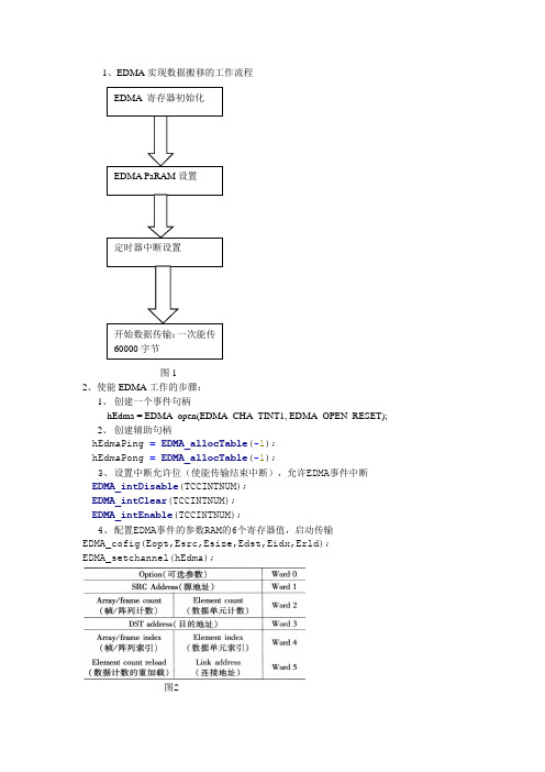
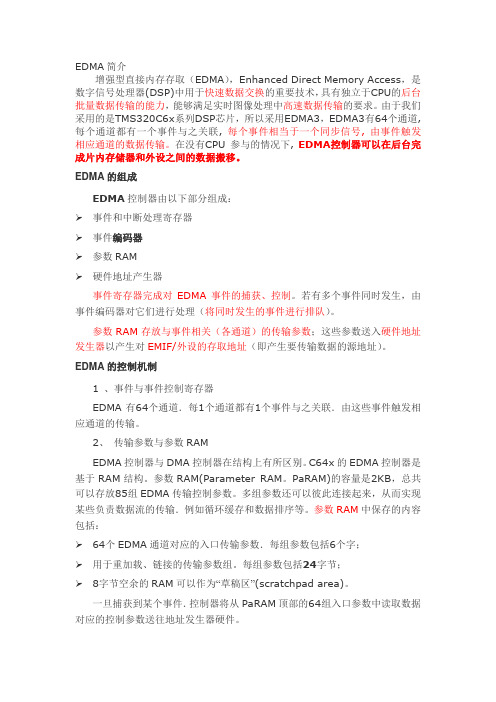
1、EDMA 实现数据搬移的工作流程图12、使能EDMA 工作的步骤:1、 创建一个事件句柄hEdma = EDMA_open(EDMA_CHA_TINT1, EDMA_OPEN_RESET);2、 创建辅助句柄hEdmaPing = EDMA_allocTable (-1);hEdmaPong = EDMA_allocTable (-1);3、 设置中断允许位(使能传输结束中断),允许EDMA 事件中断EDMA_intDisable (TCCINTNUM);EDMA_intClear (TCCINTNUM);EDMA_intEnable (TCCINTNUM);4、 配置EDMA 事件的参数RAM 的6个寄存器值,启动传输EDMA_cofig(Eopt,Esrc,Esize,Edst,Eidx,Erld);EDMA_setchannel(hEdma);图2EDMA_Config cfgEdmaPing ={EDMA_OPT_RMK(EDMA_OPT_PRI_LOW,EDMA_OPT_ESIZE_32BIT,EDMA_OPT_2DS_NO,EDMA_OPT_SUM_NONE,EDMA_OPT_2DD_NO,EDMA_OPT_DUM_INC,EDMA_OPT_TCINT_YES,EDMA_OPT_TCC_OF(TCCINTNUM),EDMA_OPT_LINK_YES,EDMA_OPT_FS_NO ), //配置Option参数EDMA_SRC_OF(&ping_data), //配置源地址EDMA_CNT_OF(BUFF_SZ), //配置计数单元EDMA_DST_OF(ping), //配置目的地址EDMA_IDX_OF(0x00000004),//配置索引EDMA_RLD_OF(0x00000000) //配置重加载或链接};5、结束EDMA关闭中断使能,请各事件标志寄存器3、乒乓缓冲传输方式分析为了协调CPU数据处理和DMA数据传输的节奏,采用一种在存储器中开设收发缓冲区的技术,即乒乓缓冲(Ping-Pong Buffering)又称双缓冲(Double Buffering),一般有Ping和Pong两组缓冲区,其中一组缓冲区传输数据,另一组处理数据。

摘要:增强型直接内存访问EDMA 是DSP 中一种高效的数据传输模块,能够不依赖CPU 进行数据的搬移,是在高速接口的使用中,十分重要的设备。
与之前的EDMA 模块相比,EDMA3在传输的同步方式、地址跳变、触发方式上都变得更为灵活。
在TI 的新型DSP 中,外设根据数据传输是否依赖EDMA3 而分成了2 种。
AIF 是一种高速接口模块,用于基带模块与射频模块间数据的传输。
该接口需要EDMA3 为其提供待传输的数据及搬移已接收的数据。
本文介绍了TI DSP 中的新一代EDMA3 模块的结构及参数配置,并结合多核心DSP TMS320C6474 中的高速AIF 接口,给出了一种EDMA3 的配置方式,为高速接口模块的使用,打下基础。
关键词:DSP;EDMA3;TMS320C6474;AIF0 引言TMS320C6474 是TI 推出的推出的一款高性能多核心DSP,基于65nm 工艺,在单一的裸片上集成了3 个1GHz 的C64x+内核,实现了3GHz 的原始DSP 性能。
显著降低了成本和功耗,并节省板级空间,使设计人员不必在电路板上集成多个数字信号处理器就能完成诸如同时执行多通道处理任务或同时执行多软件应用等高强度、高性能任务。
在TMS320C6474 DSP 中,C64x+核心、EDMA3 及片上外设是通过2 种交换网络互连的。
交换网络使主从器件间能够进行低延时的多路数据传输。
通过交换网络,CPU 能够向VCP2 发送数据而不影响RAC 与DDR2 内存控制器间的数据传输。
当对系统中的从设备进行访问时,交换网络能够对多个主设备进行仲裁。
片上外设可以分为两类:主设备及从设备。
主设备是指能够不使用EDMA3 就能在系统中进行读写操作的设备;从设备指必须使用EDMA3 才能进行数据传输的设备。
AIF 接口(Antenna Interface)是TMS320C6474 中的一种高速接口,是一种从设备,用于基带模块与射频模块间天线数据的传输,在使用OBSAI 协议时,单条链路速率最高可达4x 即3.072Gbps。

EDMA简介增强型直接内存存取(EDMA),Enhanced Direct Memory Access,是数字信号处理器(DSP)中用于快速数据交换的重要技术,具有独立于CPU的后台批量数据传输的能力,能够满足实时图像处理中高速数据传输的要求。
由于我们采用的是TMS320C6x系列DSP芯片,所以采用EDMA3,EDMA3有64个通道, 每个通道都有一个事件与之关联, 每个事件相当于一个同步信号, 由事件触发相应通道的数据传输。
在没有CPU 参与的情况下, EDMA控制器可以在后台完成片内存储器和外设之间的数据搬移。
EDMA的组成EDMA控制器由以下部分组成:事件和中断处理寄存器事件编码器参数RAM硬件地址产生器事件寄存器完成对EDMA事件的捕获、控制。
若有多个事件同时发生,由事件编码器对它们进行处理(将同时发生的事件进行排队)。
参数RAM存放与事件相关(各通道)的传输参数;这些参数送入硬件地址发生器以产生对EMIF/外设的存取地址(即产生要传输数据的源地址)。
EDMA的控制机制1 、事件与事件控制寄存器EDMA有64个通道.每1个通道都有1个事件与之关联.由这些事件触发相应通道的传输。
2、传输参数与参数RAMEDMA控制器与DMA控制器在结构上有所区别。
C64x的EDMA控制器是基于RAM结构。
参数RAM(Parameter RAM。
PaRAM)的容量是2KB,总共可以存放85组EDMA传输控制参数。
多组参数还可以彼此连接起来,从而实现某些负责数据流的传输.例如循环缓存和数据排序等。
参数RAM中保存的内容包括:64个EDMA通道对应的入口传输参数.每组参数包括6个字;用于重加载、链接的传输参数组。
每组参数包括24字节;8字节空余的RAM可以作为“草稿区”(scratchpad area)。
一旦捕获到某个事件.控制器将从PaRAM顶部的64组入口参数中读取数据对应的控制参数送往地址发生器硬件。
表1给出1组EDMA传输参数的内部结构,总共6个字.192bit。
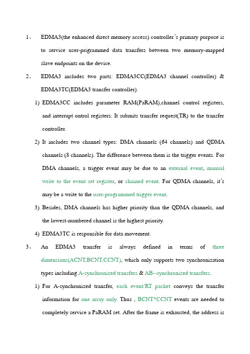
1、EDMA3(the enhanced direct memory access) controller’s primary purpose isto service user-prigrammed data transfers between two memory-mapped slave endpoints on the device.2、EDMA3 includes two parts: EDMA3CC(EDMA3 channel controller) &EDMA3TC(EDMA3 transfer controller).1)EDMA3CC includes parameter RAM(PaRAM),channel control registers,and interrupt ontrol registers. It submits transfer request(TR) to the transfer controller.2)It includes two channel types: DMA channels (64 channels) and QDMAchannels (8 channels). The difference between them is the trigger events. For DMA channels, a trigger event may be due to an external event, manual write to the event set register, or chained event. For QDMA channels, it’s may be a write to the user-programmed trigger event.3)Besides, DMA channels has higher priority than the QDMA channels, andthe lowest-numbered channel is the highest priority.4)EDMA3TC is responsible for data movement.3、An EDMA3 transfer is always defined in terms of threedimensions(ACNT,BCNT,CCNT), which only supports two synchronization types including A-synchronized transfers & AB--synchronized transfers.1)For A-synchronized transfer, each event/RT packet conveys the transferinformation for one array only.Thus ,BCNT*CCNT events are needed to completely service a PaRAM set. After the frame is exhausted, the address isupdated by adding SRCCIDX/DSTCIDX to the beginning address of the last array in the frame.2)For AB--synchronized transfers, each event/RT packet conveys the transferinformation for one entire frame of BCNT arrays of ACNT bytes. Thus , CCNT events are needed to completely service a PaRAM set. After the frame is exhausted, the address is updated by adding SRCCIDX/DSTCIDX to the beginning address of the beginning array in the frame.4、Each event queue is 16 deep. There are three event queues(Q0,Q1,Q2) forDM643 device, they submit TRs(transfer requests) to TC0,TC1,TC2 respectly.1)Each event queue is serviced in a FIFO order, and a lower numbered queuehas a higher dequeuing priority than a higher numbered queue.2)We can get the event entries by accessing the event entry registers(Q0E0 toQ2E15) which contains the type of event(manual event, chained or autotriggered) and the event number.3)The priorities of transfer requests are programmed using the queue proirityregister(QUEPRI).4)When an event reashes the head of the queue, the PaRAM associated withthat channel is read to determine the transfer details.5、Each PaRAM set includes eight 4-bytes PaRAM set entries(32-bytes total perPaRAM set).1)The PaRAM structure supports ping-pong, circular buffering,channelchaining, and autoreloading(lingking).2)A null PaRAM set is defined as a PaRAM set where all countfileds(ACNT,BCNT,CCNT) are cleared to 0. In this case, the bits corresponding to the channel is set in the event missing register(EMR, EMRH,or QEMR) and secondary event register(SER,SERH,QSER), therefor, any future event on this channel is ignored, this is an error condition,and you must clear the bit in SER,SERH,QSER.3)A dummy PaRAM set is defined as a PaRAM set where at least one countfileds(ACNT,BCNT,CCNT) is cleared to 0and at least one count fileds(ACNT,BCNT,CCNT) is nonezero. In this case, it will not set the bit in EMR, EMRH,or QEMR, and will clear the bit in the SER,SERH,QSER. It is not an error condition.4)Parameter set uodates: for nonfinal event, this includes address and countupdates, for final event, this includes the link updates. For A-synchronized, this incudes BCNT, CCNT, SRC, DST. For AB-synchronized, this incudes CCNT, SRC, DST.5) Linking transfer only occurs when the STATIC bit in OPT is cleared to 0.when the current PaRAM set event parameters have been exhausted, it reloads the another PaRAM set specified by the LINK field. We can also use a single QDMA channel and multiple PaRAM sets to create a linked list of transfer.6)link-to-self6、There are three ways the EDMA3CC gets informed about a transfer completion:1)normal completion, when the EDMA3CC receives the TCC from theEDMA3TC.2)early completion,. When the EDMA3CC submits the TR to the EDMA3TC.3) and dummy/null completion,7、The mapping between the DMA channel numbers and the PaRAM sets is fixed.The mapping between the QDMA channel numbers and the PaRAM sets is programmbale using QDMA channe n mapping register(QCHMAPn).8、The EDMA3CC divides its address space into four regions. We should make aunique assignment of QDMA/DMA cgannels to a given region.9、Chining EDMA3 channels: it allows the completion of an EDMA3 channeltransfer to triger another EDMA3 channel transfer.1) the difference between link and chaining: link reloads the cunrrent channelparameter set with the linked parmeter set, while chaining provides a synchronizaton event to the chained channel.2) there are three types: final transfer completion chaning, intermediate transfercompletion chaning, both final and intermediate transfer completion chaning 10、EDMA3 interrupts: transfer completion interrupts & error interrupts.1) transfer completion interrupts: The EDMA3 generates a single completioninterrupt per shadow region and one for the global region. TCC value is directly mapped to the bits of the (interrupt pending register)IPR/IPRH.Besides,TCC can be programmed to any value for a DMA/QDMA channel.2) for enabling transfer completion interrrupts, we should set IER/IERH,IPR/IPRH, and if in the shadow region, we should also set DRAE/DRAEH.3) for clearing transfer completion interrrupts, we can write a 1to thecorresponding bit in the interrupt pending clear register(ICR/ICRH).4) The EDMA3CC has interrupt evaluate registers(IEV AL) in each shadowregion. These IEV AL are the only registers that are not affected by the SRAE/DRAEH. A write of 1 to the EV AL bit in IEV AL will result in pulsing the associated region interrupt, which assures that the interupts sre not missed by the CPU.5) The EDMA3CC has an error evaluate registers(EEV AL) in global region. Awrite of 1 to the EV AL bit in EEV AL will result in pulsing the error interrupt.6) error interrupts: there are four conditions causing the error interrupts to bepaulsed, including a)DMA missed event for all 64 DMA channels, which get latched in the event missed registers(EMR/EMRH). b)QDMA missed events for all QDMA channels, which get latched in the QDMA event missed register(QEMR). c)threshod exceed for all event queues, which get latched in the EDMA3CC error register (CCERR). d) TCC error for outstanding transfer requests exceeding the maximum limit of 63.11、we can use the event queue entry register(QxEx)which idenfies the specificevent type & event number and the queue status register(QSTATn) which includes start pointer(STRTPTR) & the total number of valid entries (NUMV AL)to read all event entries.12、we can track queue resource by reading the queue watermark threshold Aregister(QW AMTHRA) including threshold value(0~15), the queue staus register(QSTATn) including the maximum queue usage in the watermark (WM) field or the NUMV AL bit. If the queue usage is exceeded, we can know it by reading the QTHRXCDn bit in the channel controller error register(CCERR) and the THRXCD bit in the QSTATn.13、performance tuning: we can set read command rate register(RDRATE) whichdefines the number of cycles that the EDMA3TC read controller waits before issuing subsequent commands for a given TR. While writes always have an interval between commands.14、we can use t he DMA program register set,DMA source active register set, andt he destination FIFO register set to derive a brief history of Trsserviced through the transfer controller. Besides we can know the ongoing activity in different parts of the transfer controller by reading EDMA3TC status register (TCSTAT)which includes SRCACTV bit indicating whether the source active set is active, DSTACTV bit indicating the number of TRs resident in the destination register active set, and PROGBUSY bit indicating whether a valid TR is present in the DMA pragram set.15、the destination FIFO register pointer is implemented as a circular buffer withthe start pointer being DFSTRPTR and a buffer depth of usually 2 or 4.16、when configuring the EDMA3TC, the DBS for each transfer contraller isconfugurable by a system module register(EDMATCCFG) to 16, 32, or 64 bytes.17、tirgger source priority: event trigger(via ER) is higher priority than chaintrigger(via CER) and chain trigger is higher priority than manual trigger(via ESR).18、the EDMA3 channel controller and transfer controller are clocked from PLL1.the EDMA3 system runs at DSP frequency divided by 3. On DM643 ,this is 153 MHZ in normal mode(DSP operating at 459 MHZ) or 198 MHZ in turbo mode(594 MHZ).19、power management: the EDMA3 controller can be idled on receiving a clockstop request from the PSC, and the request to EDMA3CC and EDMA3TC are separate. Before doing this, we can get conditions by reading the channel controller status register(CCSTAT) and TCSTAT.1) when putting the EDMA3 controller in reduced-power modes, we had betterfirst disable the EDMA3CC and then the EDMA3TCs.2) if ESMA3 is servicing a peripheral ,we had better first diasble the peripheral,then disable the DMA channel associated with the peripheral, then disable the EDMA3CC, and finally disable the EDMA3TCs.20、nonbursting peripheral includes the on-chip multichannel buffered serialport(McBSP). The McBSP transmit and receive data streams are treated independently by EDMA3. besides the serial data has a high priority. Then the corresponding DMA channel should be programmed to be on queue 0. 21、bursting peripheral :。
C6455 EDMA应用介绍一、EDMA调用操作流程1、EDMA初始化.函数:void CSL_edma3Init(CSL_Edma3Context * pContext);2、打开EDMACSL_edma3Open(&edmaObj,CSL_EDMA3,NULL,&status);3、EDMA module setupCSL_edma3HwSetup(hModule,&hwSetup);4、Setup the DRAE masksCSL_edma3HwControl(hModule,CSL_EDMA3_CMD_DMAREGION_ENABLE, \®ionAccess);5、Channel openCSL_edma3ChannelOpen(&chObj, CSL_EDMA3, &chAttr, &status);6、Get the parameter handleCSL_edma3GetParamHandle(hChannel,0,&status);7、EDMA parameter entry setupEDMA通道参数入口:①OPT选项参数PRI:优先级设定1:高优先级0:低优先级ESIZE:传输的元素大小0:32bit(64x为64bit)1:16bit2:8bitSYNCDIM:选择数据为1d,或是2d结构0:1d1:2dSAM:源地址变化方式1:不变0:自增DAM:目的地址变化方式1:不变0:自增TCINTEN:当全部数据传输完成,如果该位为1,将产生对应通道(TCC值)发送完成中断。
用于链接发送或中断产生。
0:禁止中断1:允许中断TCC:发送完成中断的通道号TCCM: 与TCC组合成6位数的通道号②SRC源操作数地址③CNT 传输的长度④DST目的操作数地址⑤IDX 通道索引参数⑥RLD 通道链接/重载参数8、Set EDMA Event Enable Registers (EERH + EER)clear any pending event and then enable channel:CSL_edma3HwChannelControl(hChannel,CSL_EDMA3_CMD_CHANNEL_CLEAR,NULL);Event enable:CSL_edma3HwChannelControl(hChannel,CSL_EDMA3_CMD_CHANNEL_ENABLE,NULL);9、Enable interruptregionIntr.region = CSL_EDMA3_REGION_1 ;regionIntr.intr = 1<<TCC ;regionIntr.intrh = 0 ;CSL_edma3HwControl(hModule,CSL_EDMA3_CMD_INTR_ENABLE,®ionIntr);10、Manually trigger the channel此时,EDMA的配置全部完成,启动EDMA:CSL_edma3HwChannelControl(hChannel,CSL_EDMA3_CMD_CHANNEL_SET,NULL);二、EDMA、QDMA概念▲寄存器①PQSR:优先排队状态寄存器PQ0-3 = 1 表示无请求挂起②PQAR0-3:优先队列配置寄存器PQA表示队列长度③CIPR (CIPRL,CIPRH)64BIT EDMA通道中断挂起寄存器由硬件自动置位,=1表示该通道产生中断挂起④CIER(CIERL,CIERH)64BIT EDMA通道中断使能寄存器当通道相应位=1时,该通道允许中断⑤CCER(CCERL,CCERH)64BIT EDMA通道链接使能寄存器用于链接触发多个通道传输⑥ERL、ERH事件寄存器不管事件是否使能,只要有相应通道事件发生,都会更新ERL和ERH⑦EERL,EERH事件使能寄存器当相应通道事件使能后,可以允许中断等操作。
EDMA概要①EDMA数据传输有两种发起方式:üCPU发起的EMDA数据传输(非同步方式):需要传输时,CPU设置ESR 寄存器的相应位为1,从而触发一个EDMA事件的产生,事件对应的通道参数被送往地址硬件并且完成相应的处理,这种非同步方式的实时数据传输无需设定EER寄存器;ü事件触发方式EDMA数据传输(同步方式):ER寄存器保存外设发送过来的事件,一旦CPU设置EER寄存器的相应位为1后,ER中的事件才会提交给事件编码器(Event Encoder),并且进一步引起相关的传输参数的发送给地址产生硬件;如果EER中对应于某事件的位没有置1,则ER寄存器中的事件将保留,一旦置1则触发EDMA的传输,这种特性可以应用到EDMA Chain传输,需要EER和CCER结合使用;②EDMA每个通道是和特定的系统事件绑定的,如下表所示:③EDMA Chain Transfer:一个通道传完继续传另一个通道;④EDMA Link Tansfer:设定参数后,通道的数据传输传完,再载入这个通道的其他参数设定,再进行数据传输;(2)EDMA数据传输类型:EDMA有两种类型的数据传输:1D和2D的(OPT.2DS和OPT.DDS标示源地址和目的地址的数据传输类型,即有4种组合方式);数据的维数表明了数据的组成方式:①1D数据数据组成是“块->帧->元素”;一个块中的每帧数据是独立处理(即可以理解亦为2D数据,但是第二维永远是1),每次处理是一个元素,因此一帧中的数据元素可以是在同一个内存地址、连续的地址或者是与同一帧中的前面的数据元素地址具有一定偏移(Offset,由ELEIDX通道参数指定)的某地址;不同帧之间的内存地址偏移由FRMIDX通道参数指定(两帧的第一个元素之间的偏移或者后一帧的第一个元素的地址与前一帧的最后一个元素地址的偏移,具体依赖于通道参数FS的设定);每帧的数据元素个数可以不同,由通道参数ELECNT指定,传完一帧数据后由ELERLD重新载入块中的下一帧的数据元素个数ELECNT;块中的帧的个数由通道参数FRMCNT指定;1D数据传输有两种同步方式:OPT.FS=0,元素同步方式;OPT.FS=1,帧同步方式;元素同步时,一次同步事件引起一帧中的一个元素的传输,每传输一次ELECNT递减1;当同步事件触发时,ELECNT=1表明是一帧的最后一个数据元素,此时EDMA控制器除了完成最后这个元素的传输外,还需要重新载入ELECNT(通过ELERLD)并且FRMCNT递减1;ELEIDX表示元素之间的偏移,FRMIDX表示一帧的最后一个元素和下一帧的第一个元素之间的偏移;如果OPT.LINK=1时,传输完成中断产生(FRMCNT=0)就重新从PRAM中载入当前通道的其他参数;帧同步时,一次同步事件引起一帧数据的传输,FRMIDX表示两帧的第一个元素之间的偏移;② 2D数据数据组成为“块->数组->元素”,同一数组中的元素是连续存放的,因此ELEIDX无意义;数组中的元素素引表示2D的第一维,块中的数组索引表示2D的第二维;FRMIDX的值依赖于OPT.FS的设定;OPT.FS=0:表示一次同步事件传输一个数组,此时FRMIDX是数组首地址之间的偏移;每传完一个数组,FRMCNT递减1;当OPT.LINK=1并且FRMCNT递减至0时,从PRAM的中重新载入当前通道的其他参数;OPT.FS=1:表示一次同步事件传输一个块;FRMIDX表示前一个数组的最后一个元素的地址与后一个数组的第一个元素的地址之间的偏移;如果OPT.LINK等于1,则当整块数据传完时,重新从PRAM中为当前通道载入新的参数;(3)EDMA传输过程的源/目的地址的修改在每次同步事件触发EDMA数据传输,并且传输完成后,需要对源/目的地址进行更新;地址的更新方式由SUM/DUM进行设定,并且和2DS、2DD以及FS是密切相关的;(4)数据元素大小和对齐方式源/目的地址是在元素大小的边界对齐的,因此要注意指向源/目的地址的指针的类型需要和OPT.ESIZE匹配;(5)FRMCNT和ELEMCNT的更新QUESTION:每次进行计数更新时,ELERLD的值哪里来的??(6)EDMA Linking Transfer当传输完成时(根据当前通道参数设定已经传完所有数据了,具体条件如下表所示),并且OPT.LINK=1,EDMA控制器会根据通道参数LINK(非OPT.LINK,16bits)从PaRAM中的其他位置(以24个字节对齐,因为通道参数为6WORD)重新载入当前传输通道的参数;可以链接到一个空的通道参数集(NULL Parameter)来停止EDMA传输,也可以自链接(用于循环缓冲处理或者重复的数据传输);Linking过程中不对相关寄存器作判定;(7)EDMA中断C64X DSP的EDMA控制器的所有64个通道只产生一种中断:EDMA_INT。
4.6 EDMA编程Programming the EDMAThere are three methods available for programming the EDMA:(1)Writing directly to the EDMA registers.(2)Using the Chip Support Library (CSL).(3)Graphically using the DSP/BIOS GUIinterface.Programming the EDMA -CSL(2)Using the Chip Support Library:♦The CSL provides a C language interface forconfiguring and controlling the on-chipperipherals, in this case the EDMA.♦The library is modular with each modulecorresponding to a specific peripheral. Thishas the advantage of reducing the code size.♦Some modules rely on other modules alsobeing included, for example the IRQ module isrequired when using the EDMA module.1.#include <csl.h >#include <csl_timer.h Timer Example:♦Library and individual module header files♦Library and individual module header files1.#include <csl.h >#include <csl_timer.h 2.TIMER_Handle myHandle Timer Example:♦Library and individual module header files 2.Declare Handle♦For periph’s with multiple resources♦Library and individual module header files 2.Declare Handle ♦For periph’s with multiple resources1.#include <csl.h >#include <csl_timer.h 2.TIMER_Handle myHandle 3.TIMER_Config myConfig Timer Example:♦Library and individual module header files 2.Declare Handle♦For periph’s with multiple resources 3.Define Configuration♦Create variable of configuration values♦Library and individual module header files 2.Declare Handle ♦For periph’s with multiple resources 3.Define Configuration ♦Create variable of configuration values♦Library and individual module header files 2.Declare Handle♦For periph’s with multiple resources 3.Define Configuration♦Create variable of configuration values 4.Open peripheral♦Reserves resource; returns handle♦Library and individual module header files 2.Declare Handle ♦For periph’s with multiple resources 3.Define Configuration ♦Create variable of configuration values 4.Open peripheral ♦Reserves resource; returns handle 1.#include <csl.h >#include <csl_timer.h 2.TIMER_Handle myHandle 3.TIMER_Config myConfig 4.myHandle = TIMER_open Timer Example:♦Library and individual module header files 2.Declare Handle♦For periph’s with multiple resources 3.Define Configuration♦Create variable of configuration values 4.Open peripheral♦Reserves resource; returns handle 5.Configure peripheral♦Applies your configuration to peripheral♦Library and individual module header files 2.Declare Handle ♦For periph’s with multiple resources 3.Define Configuration ♦Create variable of configuration values 4.Open peripheral ♦Reserves resource; returns handle 5.Configure peripheral ♦Applies your configuration to peripheral 1.#include <csl.h >#include <csl_timer.h 2.TIMER_Handle myHandle 3.TIMER_Config myConfig 4.myHandle = TIMER_open 5.TIMER_config (myHandle Timer Example:Technical Training OrganizationTTO(3)DSP/BIOS GUI InterfaceWith this method the configuration structure is created graphically and the setup code isgenerated automatically.(1)Create a configurationusing the EDMAconfiguration manager.Procedure:(2)Right click and select “Properties”, see thefigure below, and then select “Advanced”andfill all parameters as shown below.Procedure:(3)If you are using symbolic parameters such as“in_data”you need to declare it in the “CSLExtern Declaration”, see below figure.Procedure:(4) A file is then generated that contains theconfiguration code. The file generated forthis example is shown on the next slide.4.7 利用CSL编写EDMA程序EDMA Reg Valuesoptions 0x51200001source &loc_8count 0x00000004dest &myDest index 0x00000000rld:lnk0x00000000EDMA Reg Values options 0x51200001source &loc_8count 0x00000004dest &myDest index 0x00000000rld:lnk 0x00000000Traditional Way to Setup Peripherals 1.Determine register field values pute Hex value for register 3.Write hex values to register with CIs there an easier way to program these registers?OptionsSource Destination IndexLink Addr Cnt Reload 310Transfer Count ESIZE10# Elements4151631# Frames (less one)FS 1SUM 01DUM 01Exercise 1, Step 3: EDMA_Config EDMA_Config gEdmaConfig = {EDMA_OPT_RMK(EDMA_OPT_PRI_,// Priority?EDMA_OPT_ESIZE_,// Element size?EDMA_OPT_2DS_,// Is it a 2 dimensional src?EDMA_OPT_SUM_,// Src update mode?EDMA_OPT_2DD_,// Is it a 2 dimensional dst?EDMA_OPT_DUM_,// Dest update mode?EDMA_OPT_TCINT_,// Cause EDMA interrupt?EDMA_OPT_TCC_OF(),// Transfer complete code?EDMA_OPT_LINK_,// Enable linking (autoinit)?EDMA_OPT_FS_,// Use frame sync?),EDMA_SRC_OF(),// src address?EDMA_CNT_OF(),// Count = buffer sizeEDMA_DST_OF(),// dest address?EDMA_IDX_OF( 0 ),// frame/element index value?EDMA_RLD_OF( 0 )// reloadExercise 1, Step 3: EDMA_Config EDMA_Config gEdmaConfig = {EDMA_OPT_RMK(EDMA_OPT_PRI_LOW,// Priority?EDMA_OPT_ESIZE_16BIT,// Element size?EDMA_OPT_2DS_NO,// Is it a 2 dimensional src?EDMA_OPT_SUM_INC,// Src update mode?EDMA_OPT_2DD_NO,// Is it a 2 dimensional dst?EDMA_OPT_DUM_INC,// Dest update mode?EDMA_OPT_TCINT_NO,// Cause EDMA interrupt?EDMA_OPT_TCC_OF(0 ),// Transfer complete code?EDMA_OPT_LINK_NO,// Enable linking (autoinit)?EDMA_OPT_FS_YES// Use frame sync?),EDMA_SRC_OF( gBuf0),// src address?EDMA_CNT_OF(BUFFSIZE),// Count = buffer sizeEDMA_DST_OF( gBuf1 ),// dest address?EDMA_IDX_OF( 0 ),// frame/element index value?EDMA_RLD_OF( 0 )// reload4.8 DMA 与EDMA比较CPUProgram CacheData Cache。