HUAWEI_EM770W模块规格书
- 格式:pdf
- 大小:1013.06 KB
- 文档页数:30
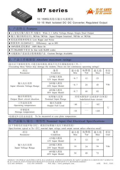
M 7 series10-15W隔离稳压输出电源模块DC -DC 电源模块DC -DC converter10-15 Watt Isolated DC -DC Converter ,Regulated Output(超出以下极限值使用,可能会损坏模块,模块不允许在极限值持续工作。
)(Exceedingthese Values may damage the module .These are not continuous operating ratings )输出短路情况OutputShort circuit duration工作温度范围Operating temperature 存储温度Storage temperature-0.7-0.7-0.7122448Vdc458523Indefinite &Auto -restart 持续短路保护/过流保护(自恢复)输出为满载Output Full Load-40---+85-55---+105*请测试外壳的表面温度To be measured at case plate temperature标称输入范围Nominal Input Range (以下参数均在室温环境+25,模块在标称输入电压下测试得到)℃(Speci fications typi cal at Ta =+25,nom inal input vol tage ,rated out put cur rent unl ess other wise not ed )℃Input Absoute Voltage Range 输入电压范围24V Input Model 24V 输入模块12V Input Model12V 输入模块48V Input Model48V 输入模块℃---项目Parameter条件Condition 最小值Min 标称值Typ 最大值Max 单位Unit91836122448Vdc367218Input Voltage Range 输入电压范围24V Input Model 24V 输入模块12V Input Model12V 输入模块48V Input Model48V 输入模块项目Parameter条件Condition 最小值Min 标称值Typ 最大值Max 单位Unit负载调整率Load Regulation (%)Max------单输出模块Single Output Model 0.5线性调整率Line Regulation 双输出模块Dual Output Model 输出为满载Output Full Load输出电压精度Output Voltage Accuracy 输入电压Input Voltage (Vdc )温度漂移系数Temperature Coefficient 工作频率Switching Frequency Hz %/℃交叉调整率Load cross Regulation Dual Output Model 双输出模块Load 20/100%60Seconds /0.5mA输入/输出隔离高压Isolation Voltage 绝缘电阻Isolation Resistance500VdcVdc M Ω1000------0.5------------5.0---2.01.0%%%%%标称输入电压Nominal Input---2500.010.02---------------(以下参数均在室温环境+25,模块在标称输入电压下测试得到)℃输出电流Output Current (mA )Max 输出电压Output Voltage (Vdc )输出纹波Output Ripple (MV )Typ 输入静态电流Input Current @No Load (mA )Typ 负载调整率Load Regulation 转换效率Efficiency (%)TypModel No . 产品型号10W 单输出系列 10W Single Output Series3.35303091215200011128346673.35912153.359M7-1215S10M7-123.3S10M7-1205S10M7-1212S10M7-1209S100.5标称输入电压Nominal Input (Speci fications typi cal at Ta =+25,nom inal input vol tage ,rated out put cur rent unl ess other wise not ed )℃1313121313766885441016102910009571041508502514479521260257254161820141826283022242628300.50.50.50.50.50.50.50.50.50.50.50.50.582818387808283818780808182M7-1224S104172424121016220.5825514320.581M7-2415S10M7-243.3S10M7-2405S10M7-2412S10M7-2409S10M7-2424S10M7-483.3S10M7-4805S10M7-4809S10189~7236~3618~Input Current @Max Load(mA )Typ 载电流输入满---3030200011128346674173030200011121.5K /3K备注:1、以上均为标准输出电压,即3.3V ,5V ,9V ,12V ,15V .M7-XXXXDX 为根据客户需求设计产品。

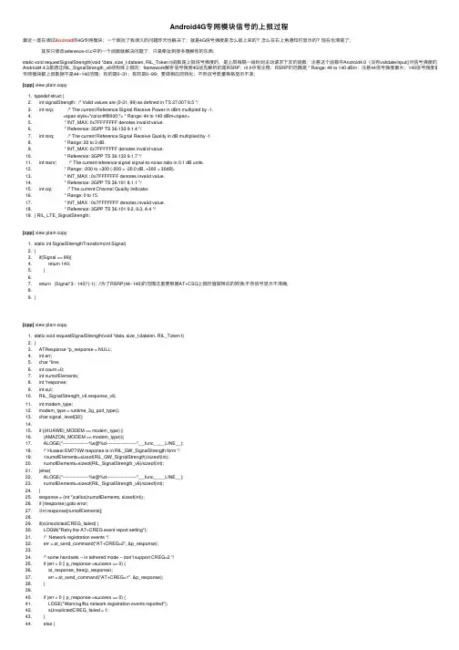
Android4G专⽹模块信号的上报过程最近⼀直在调试Android的4G专⽹模块;⼀个困扰了我很久的问题昨天也解决了;就是4G信号强度是怎么报上来的?怎么在右上⾓通知栏显⽰的?现在也清楚了;其实只修改reference-ril.c中的⼀个函数就解决问题了,只是牵扯到很多理解性的东西;static void requestSignalStrength(void *data, size_t datalen, RIL_Token t)函数是上报信号强度的,是上层每隔⼀段时间主动请求下发的函数;注意这个函数中Android4.0(没有validateInput()对信号强度的验证)和Android4.4.3是通过RIL_SignalStrength_v6结构体上报的;framework解析信号强度4G优先解析的是RSRP;ril.h中有注释:RSRP的范围是 * Range: 44 to 140 dBm;注意44信号强度最⼤;140信号强度最⼩;⼏乎所专⽹模块都上报数据不是44~140范围;有的是0~31;有的是0~99;要做相应的转化;不然信号质量格格显⽰不准;[cpp] view plain copy1. typedef struct {2. int signalStrength; /* Valid values are (0-31, 99) as defined in TS 27.007 8.5 */3. int rsrp; /* The current Reference Signal Receive Power in dBm multipled by -1.4. <span style="color:#ff0000;"> * Range: 44 to 140 dBm</span>5. * INT_MAX: 0x7FFFFFFF denotes invalid value.6. * Reference: 3GPP TS 36.133 9.1.4 */7. int rsrq; /* The current Reference Signal Receive Quality in dB multiplied by -1.8. * Range: 20 to 3 dB.9. * INT_MAX: 0x7FFFFFFF denotes invalid value.10. * Reference: 3GPP TS 36.133 9.1.7 */11. int rssnr; /* The current reference signal signal-to-noise ratio in 0.1 dB units.12. * Range: -200 to +300 (-200 = -20.0 dB, +300 = 30dB).13. * INT_MAX : 0x7FFFFFFF denotes invalid value.14. * Reference: 3GPP TS 36.101 8.1.1 */15. int cqi; /* The current Channel Quality Indicator.16. * Range: 0 to 15.17. * INT_MAX : 0x7FFFFFFF denotes invalid value.18. * Reference: 3GPP TS 36.101 9.2, 9.3, A.4 */19. } RIL_LTE_SignalStrength;[cpp] view plain copy1. static int SignalStrengthTransform(int Signal)2. {3. if(Signal == 99){4. return 140;5. }6.7. return (Signal*3 - 140)*(-1); //为了RSRP(44~140)的范围这⾥要根据AT+CSQ上报的值做相应的转换;不然信号显⽰不准确;8.9. }[cpp] view plain copy1. static void requestSignalStrength(void *data, size_t datalen, RIL_Token t)2. {3. ATResponse *p_response = NULL;4. int err;5. char *line;6. int count =0;7. int numofElements;8. int *response;9. int out;10. RIL_SignalStrength_v6 response_v6;11. int modem_type;12. modem_type = runtime_3g_port_type();13. char signal_level[32];14.15. if ((HUAWEI_MODEM == modem_type) ||16. (AMAZON_MODEM == modem_type)){17. ALOGE("------------------%s@%d---------------------",__func__,__LINE__);18. /* Huawei EM770W response is in RIL_GW_SignalStrength form */19. //numofElements=sizeof(RIL_GW_SignalStrength)/sizeof(int);20. numofElements=sizeof(RIL_SignalStrength_v6)/sizeof(int);21. }else{22. ALOGE("------------------%s@%d---------------------",__func__,__LINE__);23. numofElements=sizeof(RIL_SignalStrength_v6)/sizeof(int);24. }25. response = (int *)calloc(numofElements, sizeof(int));26. if (!response) goto error;27. //int response[numofElements];28.29. if(sUnsolictedCREG_failed) {30. LOGW("Retry the AT+CREG event report setting");31. /* Network registration events */32. err = at_send_command("AT+CREG=2", &p_response);33.34. /* some handsets -- in tethered mode -- don't support CREG=2 */35. if (err < 0 || p_response->success == 0) {36. at_response_free(p_response);37. err = at_send_command("AT+CREG=1", &p_response);38. }39.40. if (err < 0 || p_response->success == 0) {41. LOGE("Warning!No network registration events reported");42. sUnsolictedCREG_failed = 1;43. }44. else {45. sUnsolictedCREG_failed = 0;45. sUnsolictedCREG_failed = 0;46. }47. at_response_free(p_response);48. }49.50. if(sUnsolictedCGREG_failed) {51. LOGW("Retry the AT+CGREG event report setting");52. /* GPRS registration events */53. err = at_send_command("AT+CGREG=1", &p_response);54. if (err < 0 || p_response->success == 0) {55. LOGE("Warning!No GPRS registration events reported");56. sUnsolictedCGREG_failed = 1;57. }58. else {59. sUnsolictedCGREG_failed = 0;60. }61.62. at_response_free(p_response);63. }64.65. err = at_send_command_singleline("AT+CSQ", "+CSQ:", &p_response);66.67. if (err < 0 || p_response->success == 0) {68. RIL_onRequestComplete(t, RIL_E_GENERIC_FAILURE, NULL, 0);69. goto error;70. }71. memset(&response_v6, 0, sizeof(RIL_SignalStrength_v6));72.73. line = p_response->p_intermediates->line;74.75. err = at_tok_start(&line);76. if (err < 0) goto error;77. #if 078. for (count =0; count < numofElements; count ++) {79. err = at_tok_nextint(&line, &(response[count]));80. if (err < 0) goto error;81. }82. #else83. err = at_tok_nextint(&line, &out);84.85. <span style="color:#ff0000;">response_v6.LTE_SignalStrength.rsrp = SignalStrengthTransform(out);</span>86. if (err < 0) goto error;87. err = at_tok_nextint(&line, &(response_v6.GW_SignalStrength.bitErrorRate));88. if (err < 0) goto error;89. #if 190. response_v6.GW_SignalStrength.signalStrength = 99;91. response_v6.GW_SignalStrength.bitErrorRate = -1;92. response_v6.CDMA_SignalStrength.dbm = -1;93. response_v6.CDMA_SignalStrength.ecio = -1;94. response_v6.EVDO_SignalStrength.dbm = -1;95. response_v6.EVDO_SignalStrength.ecio = -1;96. response_v6.EVDO_SignalStrength.signalNoiseRatio = -1;97. response_v6.LTE_SignalStrength.signalStrength = 99;98. response_v6.LTE_SignalStrength.rsrq = 0x7FFFFFFF;99. response_v6.LTE_SignalStrength.rssnr = 0x7FFFFFFF;100. response_v6.LTE_SignalStrength.cqi = 0x7FFFFFFF;101. #endif102. #endif103. ALOGE("------------------%s@%d---------------------out=%d,signalStrengt=%d,rsrp=%d,bitErrorRate=%d",__func__,__LINE__,out,response_v6.LTE_SignalStrength.signalStrength,response_v6.LTE_SignalStrength.rsrp,response_v6.GW_SignalStrength.bitErro 104.105. RIL_onRequestComplete(t, RIL_E_SUCCESS, (int *)(&response_v6), sizeof(response_v6));106.107. at_response_free(p_response);108. free(response);109.110. //sprintf(signal_level, "link:%d,sig:%d", link_4g, response[0]);111. //WriteFile("/sdcard/tchtc/4g_signal_level.txt", signal_level);112.113. return;114.115. error:116. RLOGE("requestSignalStrength must never return an error when radio is on");117. RIL_onRequestComplete(t, RIL_E_GENERIC_FAILURE, NULL, 0);118. at_response_free(p_response);119. free(response);120.121. }信号强度的解析在framework层是通过socket 和rild接⼝通信的;ServiceStateTracker.java⽂件中onSignalStrengthResult(AsyncResult ar, boolean isGsm)会验证ril层上报的信号强度范围是否正确;[cpp] view plain copy1. protected boolean onSignalStrengthResult(AsyncResult ar, boolean isGsm) {2. SignalStrength oldSignalStrength = mSignalStrength;3.4. // This signal is used for both voice and data radio signal so parse5. // all fields6.7. if ((ar.exception == null) && (ar.result != null)) {7. if ((ar.exception == null) && (ar.result != null)) {8. mSignalStrength = (SignalStrength) ar.result;9. <span style="color:#ff0000;"> mSignalStrength.validateInput(); //验证上报的4G信号强度是否在正确范围内?</span>10. mSignalStrength.setGsm(isGsm);11. } else {12. log("onSignalStrengthResult() Exception from RIL : " + ar.exception);13. mSignalStrength = new SignalStrength(isGsm);14. }15.16. return notifySignalStrength();17. }[cpp] view plain copy1. public void validateInput() {2. if (DBG) log("Signal before validate=" + this);3. // TS 27.007 8.54. mGsmSignalStrength = mGsmSignalStrength >= 0 ? mGsmSignalStrength : 99;5. // BER no change;6.7. mCdmaDbm = mCdmaDbm > 0 ? -mCdmaDbm : -120;8. mCdmaEcio = (mCdmaEcio > 0) ? -mCdmaEcio : -160;9.10. mEvdoDbm = (mEvdoDbm > 0) ? -mEvdoDbm : -120;11. mEvdoEcio = (mEvdoEcio >= 0) ? -mEvdoEcio : -1;12. mEvdoSnr = ((mEvdoSnr > 0) && (mEvdoSnr <= 8)) ? mEvdoSnr : -1;13.14. // TS 36.214 Physical Layer Section 5.1.3, TS 36.331 RRC15. mLteSignalStrength = (mLteSignalStrength >= 0) ? mLteSignalStrength : 99;16. <span style="color:#ff0000;">mLteRsrp = ((mLteRsrp >= 44) && (mLteRsrp <= 140)) ? </span><span style="color:#3333ff;">-mLteRsrp</span><span style="color:#ff0000;"> : SignalStrength.INVALID; //RSR上报的必须是正数;</span>17. mLteRsrq = ((mLteRsrq >= 3) && (mLteRsrq <= 20)) ? -mLteRsrq : SignalStrength.INVALID;18. mLteRssnr = ((mLteRssnr >= -200) && (mLteRssnr <= 300)) ? mLteRssnr19. : SignalStrength.INVALID;20. // Cqi no change21. if (DBG) log("Signal after validate=" + this);22. }SignalStrength.Java⽂件中getLevel() 是对信号的解析;4G信号解析就是getLteLevel() 函数;[cpp] view plain copy1. public int getLteLevel() {2. /*3. * TS 36.214 Physical Layer Section 5.1.3 TS 36.331 RRC RSSI = received4. * signal + noise RSRP = reference signal dBm RSRQ = quality of signal5. * dB= Number of Resource blocksxRSRP/RSSI SNR = gain=signal/noise ratio6. * = -10log P1/P2 dB7. */8. int rssiIconLevel = SIGNAL_STRENGTH_NONE_OR_UNKNOWN, rsrpIconLevel = -1, snrIconLevel = -1;9.10. if (mLteRsrp > -44) rsrpIconLevel = -1;11. //根据RSRP信号强度转化成UI通知栏的信号强度格格;12. else if (mLteRsrp >= -85) rsrpIconLevel = SIGNAL_STRENGTH_GREAT;13. else if (mLteRsrp >= -95) rsrpIconLevel = SIGNAL_STRENGTH_GOOD;14. else if (mLteRsrp >= -105) rsrpIconLevel = SIGNAL_STRENGTH_MODERATE;15. else if (mLteRsrp >= -115) rsrpIconLevel = SIGNAL_STRENGTH_POOR;16. else if (mLteRsrp >= -140) rsrpIconLevel = SIGNAL_STRENGTH_NONE_OR_UNKNOWN;17.18. /*19. * Values are -200 dB to +300 (SNR*10dB) RS_SNR >= 13.0 dB =>4 bars 4.520. * dB <= RS_SNR < 13.0 dB => 3 bars 1.0 dB <= RS_SNR < 4.5 dB => 2 bars21. * -3.0 dB <= RS_SNR < 1.0 dB 1 bar RS_SNR < -3.0 dB/No Service Antenna22. * Icon Only23. */24. if (mLteRssnr > 300) snrIconLevel = -1;25. else if (mLteRssnr >= 130) snrIconLevel = SIGNAL_STRENGTH_GREAT;26. else if (mLteRssnr >= 45) snrIconLevel = SIGNAL_STRENGTH_GOOD;27. else if (mLteRssnr >= 10) snrIconLevel = SIGNAL_STRENGTH_MODERATE;28. else if (mLteRssnr >= -30) snrIconLevel = SIGNAL_STRENGTH_POOR;29. else if (mLteRssnr >= -200)30. snrIconLevel = SIGNAL_STRENGTH_NONE_OR_UNKNOWN;31.32. if (DBG) log("getLTELevel - rsrp:" + mLteRsrp + " snr:" + mLteRssnr + " rsrpIconLevel:"33. + rsrpIconLevel + " snrIconLevel:" + snrIconLevel);34.35. /* Choose a measurement type to use for notification */36. if (snrIconLevel != -1 && rsrpIconLevel != -1) {37. /*38. * The number of bars displayed shall be the smaller of the bars39. * associated with LTE RSRP and the bars associated with the LTE40. * RS_SNR41. */42. return (rsrpIconLevel < snrIconLevel ? rsrpIconLevel : snrIconLevel);43. }44.45. if (snrIconLevel != -1) return snrIconLevel;46.47. if (rsrpIconLevel != -1) return rsrpIconLevel;47. if (rsrpIconLevel != -1) return rsrpIconLevel;48.49. /* Valid values are (0-63, 99) as defined in TS 36.331 */50. if (mLteSignalStrength > 63) rssiIconLevel = SIGNAL_STRENGTH_NONE_OR_UNKNOWN;51. else if (mLteSignalStrength >= 12) rssiIconLevel = SIGNAL_STRENGTH_GREAT;52. else if (mLteSignalStrength >= 8) rssiIconLevel = SIGNAL_STRENGTH_GOOD;53. else if (mLteSignalStrength >= 5) rssiIconLevel = SIGNAL_STRENGTH_MODERATE;54. else if (mLteSignalStrength >= 0) rssiIconLevel = SIGNAL_STRENGTH_POOR;55. if (DBG) log("getLTELevel - rssi:" + mLteSignalStrength + " rssiIconLevel:"56. + rssiIconLevel);57. return rssiIconLevel;58.59. }。
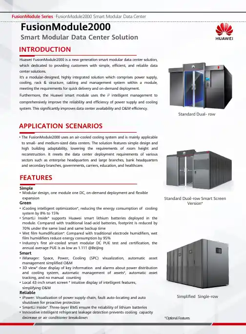
Huawei FusionModule2000is a new generation smart modular data center solution,which dedicated to providing customers with simple,efficient,and reliable data center solutions.It's a modular-designed,highly integrated solution which comprises power supply,cooling,rack &structure,cabling and management system within a module,meeting the requirements for quick delivery and on-demand deployment.Furthermore,the Huawei smart module uses the i 3intelligent management to comprehensively improve the reliability and efficiency of power supply and cooling system.This significantly improves data center availability and O&M efficiency.INTRODUCTION•The FusionModule2000uses an air-cooled cooling system and is mainly applicable to small-and medium-sized data centers.The solution features simple design andhigh building adaptability,lowering the requirements of room height and reconstruction.It meets the data center deployment requirements of various sectors such as enterprise headquarters and large branches,bank headquarters and secondary branches,governments,carriers,education,and healthcare.APPLICATION SCENARIOSSimple•Modular design, one module one DC, on-demand deployment and flexible expansionGreen•iCooling intelligent optimization*,reducing the energy consumption of cooling system by 8%to 15%•SmartLi Inside*supports Huawei smart lithium batteries deployed in the pared with traditional lead-acid batteries,footprint is reduced by 70%under the same load and same backup time•Wet film humidification*:Compared with traditional electrode humidifiers,wet film humidifiers reduce energy consumption by 95%•Industry's first air-cooled smart modular DC PUE test and certification,the annual average PUE is as low as 1.111@BeijingSmart•iManager:Space,Power,Cooling (SPC)visualization,automatic asset management simplified O&M•3D view*clear display of key information and alarms about power distribution and cooling system,automatic management of assets*,automatic asset tracking,and no manual counting•Local 43-inch smart screen *intuitive display of intelligent features,simplifying O&MReliable•iPower:Visualization of power supply chain,fault auto-locating and auto shutdown for proactive protection•SmartLi Inside* :Three-layer BMS ensure the reliability of lithium batteries •Innovative intelligent refrigerant leakage detection prevents cooling capacity decrease or air conditioner breakdownFEATURESFusionModule2000Smart Modular Data Center Solution Standard Dual-row Smart ScreenVersion*Standard Dual-rowSimplified Single-row*Optional FeaturesSPECIFICATIONSItem SpecificationsMicro Module DimensionsSingle row (with aisle containment)(L×W×H):L×2400×2410mm;L×1350×2000mm;L×1600×2000mmDual row (with aisle containment) (L×W×H): L×3600×2410mm; L×3400×2410mm;L×3600×2610mmCabinets per module Single row≤24 cabinets; dual row: ≤48cabinetsPower supply380/400/415VAC, 50/60Hz,3Ph+N+PEMax IT load per module180kW (with integrated UPS)/ 145kW (with integrated PDC)/ 310kW (with New main way)/310kW (with precision PDC)Operation conditionUltra low temperature condition: -40ºC to 45ºC(Need low-temp kit)T1 condition: -20ºC to 45ºC; T3 condition: -5ºC to 55ºC(Need T3 outdoor unit)Cable routing Routed in/out through the top of cabinetsInstallation Installing on concrete floor or raised floorCabinet Dimensions(H×W×D)2000mm×600/800mm×1200mm;2000mm×600mm×1100mm;2200mm×600/800mm×1200mmSpace available42U/47UCabinet Porosity Front and rear doors: hexagonal mesh door design, porosity rate ≥75% Protection level IP20Air-cooled In-row air conditioner Cooling capacity25kW/35kW/46kW、65kWDimensions(H×W×D)25kW:2000mm×300mm×1100mm;35kW:2000mm×600mm×1200mm;46kW/65kW:2000mm×600mm×1200mm;(Simplified Single-row can only support 46kW) Power supply380/400/415VAC, 50/60Hz,3Ph+N+PERefrigerant R410AIntegrated UPS (UPS inside)Input voltage380/400/415VAC, 50/60Hz,3Ph+N+PEInput250A/400A/630A MCCB (single input); 250A/400A ATS (dual input)Input power factor Full load > 0.99, Half load >0.98Output power factor 1.0Rated capacity30~125kVA:IT Load ≤ 120 kW, power modules ≤ 4, the capacity of a single power module is30kVAIT Load > 120 kW, power modules ≥5, the capacity of a single power module is derated to 25kVA180kVA:Supports a maximum of seven 30 kVA power modules in 6+1 redundancy mode Output IT: 40A/1P×24×2; A/C: 40A or 63A/3P×8; lighting:10A/1P×3Efficiency≥ 96% (Linear Load)AC SPD5kA,8/20μsIntegrated power distribution cabinet (UPS outside)Input voltage380/400/415VAC, 50/60Hz,3Ph+N+PEInput IT: 160A/250A MCCB; A/C: 160A/250A MCCB (single/dual input)Rated input current IT: 160A/250A, Air conditioner: 160A/250AOutput IT: 2×24×40A/1P; 2×24×63A/1P;2×8×40A/3P;A/C: 40A/3P×8 or 63A/3P×8 ; lighting:10A/1P×3AC SPD20kA,8/20μsPrecision power distribution cabinet (UPS outside)Input voltage380/400/415VAC,50/60Hz,3Ph+N+PEInput160A/250A/400A/630A MCCB (single/dual input) Output IT:40A/1P,63A/1P,40A/3P,63A/3P, max 144routesSmart busway (UPS outside)Input voltage380/400/415VAC,50/60Hz,3Ph+N+PEInput250A/400A/630A MCCB (single input)Output IT:40/1P,63A/1P,40A/3P,63A/3P(6 branches in one Power Distribution Unit)SmartLi Inside-6C Single Lithium batterycabinetContains 16 battery modules. Two battery strings are connected in parallel,andeach battery string contains eight battery modules connected in series. Number of Lithium batterycabinets2N scenario: ≤ 6battery cabinets; N+1 scenario: ≤ 3battery cabinetsTypical backup time Recommended backup time: 10/15 minutesSmartLi Inside-1C Single Lithium batterycabinetFully configured with eight battery modules. A single cabinet can be configured with 5-8 batterymodules.Number of Lithium batterycabinets2N scenario: ≤ 6battery cabinets; N+1 scenario: ≤ 3battery cabinetsTypical backup time Recommended backup time: 30/60 minutesRecommended Configurations—UPS Inside the ModuleUPS Inside the Module(Integrated UPS+SmartLi )R24 Typical Layout of the UPS and LithiumBatteries in RowR24Dual-Row Module with Lithium Batteries in RowIT IT IT IT Smart Cooling IT IT IT Smart Cooling IT IT IT Smart Cooling IT IT ITAisle ContainmentIntegrated UPS Battery cabinet Battery cabinet IT Smart Cooling IT IT IT IT IT IT IT Smart Cooling IT IT IT IT Load(kW)Power Supply Redundancy A/C Configuration Battery30Integrated UPS N+ 1/2N 25kW×2In-row (Batterycabinet)/OutsideInstallation4025kW×3 6035kW×3 8035kW×4 10046kW×4 12565kW×4 15065kW×4 18065kW×5Recommended Configurations ——UPS Outside the ModuleCopyright ©Huawei Technologies Co.,Ltd.2021.All rights reserved.No part of this document may be reproduced or transmitted in any form or by any means without prior written consent of Huawei Technologies Co.,Ltd.UPS Outside the Module(Precision PDC )UPS Outside the Module(Smart Busway)IT Load (kW)IT Power Supply AC Power Supply Redundancy AC Configuration20Integrated PDC/Precision PDC/Smart BuswayIntegrated PDC/ PowerDistribution BoxN+1/2N25kW ×23035kW ×24025kW ×36035kW ×39035kW ×412046kW ×4145SmartBusway/PrecisionPDCPower Distribution Box65kW ×416065kW ×423565kW ×631065kW ×7R24 Typical Layout of Dual-Row (Precision PDC)R24 Typical Layout of Dual-Row (Smart Busway)IT IT Smart CoolingIT IT IT IT Smart CoolingIT IT IT IT Smart CoolingIT ITR24-140kW (aisle)IT IT Smart CoolingIT IT IT IT Smart CoolingIT IT IT IT Smart CoolingIT ITIT IT Smart CoolingIT IT IT IT Smart CoolingIT IT IT IT Smart CoolingIT IT R24-140kW (aisle)Precision PDCIT Smart CoolingIT IT IT IT Smart CoolingIT IT IT IT Smart CoolingIT IT。

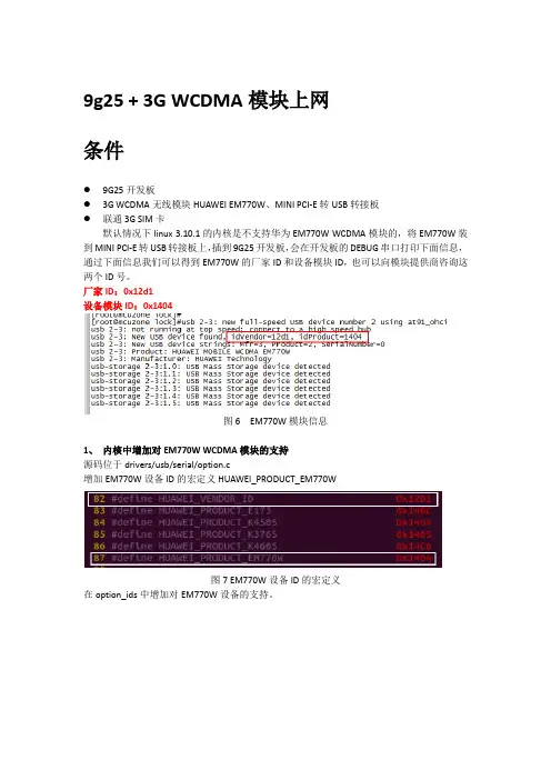
9g25 + 3G WCDMA模块上网条件●9G25开发板●3G WCDMA无线模块HUAWEI EM770W、MINI PCI-E转USB转接板●联通3G SIM卡默认情况下linux 3.10.1的内核是不支持华为EM770W WCDMA模块的,将EM770W装到MINI PCI-E转USB转接板上,插到9G25开发板,会在开发板的DEBUG串口打印下面信息,通过下面信息我们可以得到EM770W的厂家ID和设备模块ID,也可以向模块提供商咨询这两个ID号。
厂家ID:0x12d1设备模块ID:0x1404图6 EM770W模块信息1、内核中增加对EM770W WCDMA模块的支持源码位于drivers/usb/serial/option.c增加EM770W设备ID的宏定义HUAWEI_PRODUCT_EM770W图7 EM770W设备ID的宏定义在option_ids中增加对EM770W设备的支持。
图8 option_ids中增加对EM770W设备的支持2、内核配置项开启内核ppp和移植pppd过程同上,将“USB driver for GSM and CDMA modems”设成作为内核模块方式编译,设置完成重新编译内核。
图9内核编译完成后,使用下面命令生成新的驱动#make ARCH=arm CROSS_COMPILE=arm-none-linux-gnueabi- modules交叉编译完成会在drivers/usb/serial/目录生成option.ko、usb_wwan.ko两个驱动文件,将这两个文件拷贝到开发板的/lib/modules/3.10.0+目录,或者其他自定义目录。
3、加载驱动在开发板上使用下面命令加载驱动#insmod /lib/modules/3.10.0+/usb_wwan.ko#insmod /lib/modules/3.10.0+/option.ko注意驱动加载顺序,option.ko要依赖于usb_wwan.ko,驱动加载成功后将EM770W模块插到开发板USB口,如能正确识别打印图10信息,在/dev目录会产生5个ttyUSB*的虚拟USB 口,如图11,使用pppd拨号使用ttyUSB0,波特率115200。
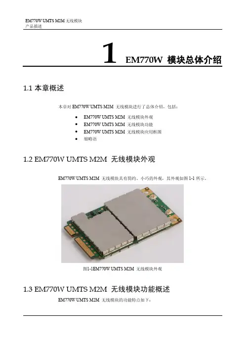
1EM770W 模块总体介绍1.1 本章概述本章对EM770W UMTS M2M 无线模块进行了总体介绍,包括:● EM770W UMTS M2M 无线模块外观 ● EM770W UMTS M2M 无线模块功能 ● EM770W UMTS M2M 无线模块应用框图 ●缩略语EM770W UMTS M2M 无线模块外观EM770W UMTS M2M 无线模块具有简约、小巧的外观,其外观如图1.21-1所示。
1.3 EM770WEM770W 图1-1EM770W UMTS M2M 无线模块外观UMTS M2M 无线模块功能概述 UMTS M2M 无线模块的功能特点如下:900/900/850和GPRS/GSM1900/1800/900/850频段; 补充业务; 口,接口信号包括: - 电源1路4线串口); 1路输入输出音频信号(只支持话柄); IM 卡); ● ● ● ●表● 支持UMTS 2100/1● 支持语音、短信、数据、电话本、● 支持内置TCP/IP 协议栈; ● 支持FOTA 功能;●提供通用Mini PCI Express 接- 2路UART 接口(支持1路7线全串口、- - 1路USIM 卡信号(支持3.0v 或1.8v US - 1路高速USB2.0接口 -PCM 接口等提供主集天线、分集天线接口;支持标准AT 指令集和华为扩展AT 指令集;支持特殊USIM 卡业务; 符合ROHS 环保认证要求。
1-1 EM770W UMTS M2M 无线模块产品特性产品特性 描述工作频段UMTS: Quad band, 850/900/1900/2100MHz 100MHzGSM/GPRS/EDGE: Quad 850/900/1800/1900MHzHSUPA /HSDPA: 850/900/1900/2band,最大发射功率EGSM/GPRS 850 SM/GPRS 900 Class 1 (+30dBm ±2dB) for GSM/GPRS 1800 2dB) for GSM/GPRS 1900100, WCDMA FDD BdI +1/-3dB) for UMTS 1900, WCDMA FDD BdII MA FDD BdVIII CDMA FDD BdVClass 4 (+33dBm ±2dB) for Class 4 (+33dBm ±2dB) for EG Class 1 (+30dBm ±Class 3 (+24dBm +1/-3dB) for UMTS 2Class 3 (+24dBm Class 3 (+24dBm +1/-3dB) for UMTS 900,WCD Class 3 (+24dBm +1/-3dB) for UMTS 850,W 正常工作温度:-10℃~+65℃ 受限工作温度:-20℃~+70℃ 工作温度 存储温度::-40℃~+90℃电源电压 3.0V ~3.6V (推荐值3.3V ) 待机模式:<3mA 功耗(电流)语音模式(平均):250mA产品特性 描述UMTS 业务3GPP Release 6rate – 384 kbps DL / 384 kbps ULHSPA data rate - 7.2 Mbps DL / 2 Mbps UL PS data CS data rate – 64 kbps DL / 64 kbps ULEDGE/GPRS/GSM 业务ps/DL: 236.8 kbpsi-slot Class 12,UL: 53.6 kbps/DL: 53.6 kbps tion Class B P, non-re tEDGE• Class 12,UL: 236.8 kb GPRS• Mult • Full PBCCH support • Mobile Sta • Coding Scheme 1 – 4CSD• V.110, RL transpa n • 14.4 kbps AT 命令 指令集支持标准AT 指令集和华为扩展AT 2x UART 接口(其中UART1为8线带流控功能串口,最大速率达230.4kbps )1路标准USIM 卡接口(3V 、1.8V ) 1路USB2.0 High Speed 接口 1路硬件复位接口 1路模拟音频接口 1路PCM 接口 LED 状态指示接口 Mini PCI Express 连接器电源接口Mini PCI Express 接口:PCI Express Mini Card Specification 1.2 对外接口天线接口:Astron 51-3612-50-H 或HRS U.FL-R-SMT-1(10) RF 连接器语音业务 语音编码 支持FR 、EFR 、HR 和AMR 的支持MO 和MT 点对点和小区广播短消息业务T 和PDU短消息模式支持TEX 补充业务 来电显示、呼叫转移、呼叫保持、呼叫等待和三方通话等 其他特性FOTA内置协议栈TCP/IP产品特性 描述物理特性 11.5±0.3g尺寸: 30x 50.9 x4.7 mm 重量: RoHS 环保 HS 环保认证要求 符合Ro 认证标准(CE0168) FCC 符合CE GCF A-tick ROHS PTCRB1.4 EM770W UMTS M2M 无线模块应用框图EM770W UMTS M2M 无线模块应用框图如图1-2所示。
Product DescriptionEM770W UMTS M2M Wireless Module V100R001Issue 1.01Date 2009-01-07HUAWEI TECHNOLOGIES CO., LTDHuawei Technologies Co., Ltd. provides customers with comprehensive technical support and service. Please feel free to contact our local office or company headquarters.Huawei Technologies Co., Ltd.Address:Huawei Industrial BaseBantian, LonggangShenzhen 518129People's Republic of ChinaWebsite: Email: support@Copyright © Huawei Technologies Co., Ltd. 2008. All rights reserved.No part of this document may be reproduced or transmitted in any form or by any means without prior written consent of Huawei Technologies Co., Ltd.Trademarks and Permissionsand other Huawei trademarks are trademarks of Huawei Technologies Co., Ltd.All other trademarks and trade names mentioned in this document are the property of their respective holders.NoticeThe information in this document is subject to change without notice. Every effort has been made in the preparation of this document to ensure accuracy of the contents, but all statements, information, and recommendations in this document do not constitute the warranty of any kind, express or implied.About This DocumentAuthorPrepared by Zhang Jun Date2008-11-05Date2008-11-20Reviewed by Zhang Haojing, Tan Yubo, Liu Penghao,Zhou Zhaoxing, Liu Qinggang, Xu Jinlong,Wang Dongjie, Cao Hepu, Lu Xiaoguang,Liu Kun, Yang Chunfan, Guo Gang, ZhuDi, Chen EnApproved by DateHistoryIssue Details Date Author Approved by1.00 Initial draft completed. 2008-11-20Zhang Jun1.01 First updated 2009-01-07Zhang JunContents1 Product Overview (7)1.1 About This Chapter (7)1.2 Appearance (7)1.3 Functions (8)1.4 Application Block Diagram (8)2 Interface Description (9)2.1 About This Chapter (9)2.2 Universal Mini PCI Express Interface (9)2.2.1 Interface Signals (9)2.3 Antenna Interfaces (12)2.3.1 Antenna Interface Circuits (12)3 Electrical Features of the Interfaces (15)3.1 About This Chapter (15)3.2 Extreme Application Conditions (15)3.3 DC characteristics of IO interfaces (16)3.4 Power Supply Features (16)3.4.1 Input Power Supply (16)3.4.2 Working Current (17)3.4.3 Power-On Process (18)4 Interface Usage (19)4.1 About This Chapter (19)4.2 UART Interface (19)4.3 UIM Card Interface (23)4.4 Audio Interface (24)4.5 Power Supply Interface (25)4.6 USB Bus (26)4.7 LED Status Indicator (27)4.8 Reset Interface (27)4.9 Pin Sequence (28)5 Structure (29)5.1 About This Chapter (29)5.2 Outline Dimensions of the EM770W UMTS M2M Wireless Module (30)5.3 Outline Dimensions of the Mini PCI Express Interface (31)1Product Overview1.1 About This Chaptervides an overview of the EM700W Universal Mobile Telecommunications ste odule, with the following information included:z Appearance z Functionsion Block Diagram1.2 Appearanceple and delicate, as This chapter pro Sy m (UMTS) M2M wireless m zApplicat The appearance of the EM770W UMTS M2M wireless module is simshown in F igure 1-1. Figure 1-1 Appearance of the EM770W UMTS M2M wireless module1.3 Functio s owing functions and features:0/1900/900/850MHz and GPRS/GSM z z zs the power interface, two serial ports (including one 8-wire full-serial ut (I/O) interface (for thee), one User Identification Module (UIM) card interface (3.0 V or1.8 niversal Serial Bus (USB) interface, and the Pulse Code Modulation z AT command sets ous Substances (RoHS) standards1.4 Application Block DiagramlessnThe EM770W UMTS M2M wireless module supports the foll z Frequency bands of UMTS 2101900/1800/900/850MHzz Audio, short message, data, and supplementary services z Built-in TCP/IP protocol stack Firmware Over The Air (FOTA)Universal Mini Peripheral Component Interconnect (PCI) Express interfaceInterfaces, such a port and one 4-wire serial port), one audio input and outp handset or earphon V), one full-speed U (PCM) interfacez Main diversity antenna and diversity antenna interfaces z Special UIM card serviceszCompliance with Restrictions on Hazard F igure 1-2 shows the application block diagram of the EM770W UMTS M2M wire module.Figure 1-2 Application block diagram of the EM770W UMTS M2M wireless module2Interface Description2.1 About This Chapternterfaces of the EM770W UMTS M2M wireless module, including:z Universal Mini PCI Express Interface 2.2 Universal Mini PCI Express Interface2.2.1 Interface Signalsthe universal Mini PCI Express interface. T able 2-1 sh h f the 52 pins of the un PCI Express interface. Table 2-1 Fu tions eThis chapter describes the i zAntenna InterfacesThe EM770W UMTS M2M wireless module adopts ows t e functions o iversal Mini nc of the Mini PCI Express interfac No.SignalI/O FunctionRemarks 1 MICP IPositive pole of the MIC inputsignal 2VCC_3V3P3.3 V DC power input3 MICN Ie pole of the MIC input Negativ signal 4 GND Power Negative pole of the p supply 5 EARP OPositive pole of the output signal to the receiver 6 Reserved - Reserved7 EARNOtive pole of the outputNega signal to the receiverNo. Signal I/O Function Remarks8 VREG_USIM_Ccard is used to power the USIM card. PPower supply output for USIM It 9 GND PNegative pole of the po supply wer 10USIM_IO_CI/OData signal of the USIM card11 UART1_RX I UART1 data receptionransistor-Transistor Logic (TTL) T level.It corresponds to the TXD signal of the PC after the level is converted. 12 USIM_CLK_C O Clock signal of the USIM card13 UART1_TX data sending TTL level.corresponds to the RXD signal of after the level is converted. O UART1It the PC 14USIM_RST_CardO Reset signal of the USIM c 15 GND PNegative pole of the power supply 16 Reserved Reserved 17UART1_RIIUART1 ringing indicationote 1. See N 18 GND PNegative pole of the power supply 19WAKEUP_NnalIModule wake-up sig 20 Reserved Reserved21 GND PNegative pole of the power supply 22 PERST_N set signal I Module re 23 UART1_CTS I/OTTL level.corresponds to the RTS signal of the PC after the level is converted. UART1 Clear-to-Send (CTS)signal It 24 Reserved dReserve 25 UART1_RFR ignal OUART1 Ready-for-Receive (RFR) s 26 GND Pole of the power Negative p supply 27 GND Pe pole of the power Negativ supply 28 ReservedReservedNo. Signal I/O FunctionRemarks 29 GND PNegative pole of the power supply 30 UART3_RFR O UART3 RFR signal 31 UART1_DTRIUART1 Data Terminal Ready (DTR) signalTTL level.It corresponds to the DTR signal of the PC after the level is converted. 32 UART3_CTS O nalUART3 CTS sig TTL level.It corresponds to the RTS signal of the PC after the level is converted. 33 UART1_DCDIData Carrier Detect TL level.It corresponds to the DCD signal of after the level is converted. UART1(DCD) signal T the PC 34 GND PNegative pole of the power supply 35 GND PNegative pole of the power supply GND 36USB_D-I/ONegative USB signal37 GND PNegative pole of the power supply 38 USB_D+ I/O USB signal Positive 39VCC_3V3P3.3 V DC power input40 GND PNegative pole of the power supply 41VCC_3V3C power inputP3.3 V D 42 LED_WWAN O LED signal43 GNDPer supply Negative pole of the pow44 UART3_RX I UART3 data reception TL level.ds to the TXD signal of T It correspon the PC after the level is converted. 45 AUX_PCM_CLK O Auxiliary CODEC PCM clock46UART3_TXOdata sendingTL level.It corresponds to the RXD signal of e PC after the level is converted. UART3T th 47 AUX_PCM_DOUT OAuxiliary CODEC PCM data output 48 ReservedReservedNo. Signal I/O Function Remarks 49 AUX_PCM_DINIAuxiliary CODEC PCM data input 50 GNDPNegative pole of the power supply51 AUX_PCM_SYNC dataprobe OAuxiliary CODEC PCM 52VCC_3V3P3.3 V DC power inputl-serial port.2.3.1 Anten Both the main diversity and the diversity antenna interfaces of the module use the 51-3612-50-H RF connector from Astron. F igure 2-1 shows the dimensions of the RF connector.Note 1: UART1 is an 8-wire ful 2.3 Antenna Interfacesna Interface CircuitsThe EM770W UMTS M2M wireless module has two antenna interfaces, namely, maindiversity and diversity. Considering antenna resistance, you need to select cables and antennas with the 50-ohm characteristic resistance.Figure 2-1Dimensions of the RF connectorThe transmit characteristics of the antenna interfaces of the module is as follows:Frequency RangeUplink(MS->BTS) Frequency RangeDownlink(BTS->MS)Power(dBm)Receiving Sensitivity ofthe Antenna Interfaces824 MHz–849 MHz 869 MHz – 894 MHz 31 < P < 33 < –108.5 dBm880 MHz–915 MHz 925 MHz – 960MHz 31 < P < 33 < –108.5 dBm1710 MHz–1785 MHz 1805 MHz – 1880MHz28 < P < 30 < –108.5 dBm GSM1850 MHz–1910 MHz 1930 MHz – 1990MHz28 < P < 30 < –108.5 dBmFrequency RangeFrequency RangePower Receiving Sensitivity of the Antenna InterfacesUplink (MS->BTS)Downlink (dBm) (BTS->MS) 824 MHz –949 MHz869 MHz – 894 MHz 21.5 < P < 24 < –109 dBm 880 MHz –915 MHz 925 MHz – 960MHz 21.5 < P < 24 < –109 dBm 1850 MHz ~1910 MHz1930 MHz – 1990MHz21.5 < P < 24 < –108 dBm WCDMA 1920 MHz –1980 MHz 2110 MHz – 2170MHz21.5 < P < 24< –109 dBmIt is recommended that the antenna whose gain value is greater than 1 dBi be used.Adjust each component parameter value according to the cabling of the user's circuit board. As reference, connected an inductance valued 68~100nH to Ground to protected against ESD. Pay attention to the resistance matching and the antistatic capability or lightning protection capability of the antennas.3Electrical Features of the Interfaces3.1 About This Chapterof the interfaces of the EM770W UMTS M2M re e Application Conditions z zThis chapter describes the electrical features wiless module, including:z Extrem DC characteristics of IO interfaces Power Supply Featuresal interfaces of the EM770W UMTS M2M e interfaces.3.2 Extreme Application Conditionsless le 3-1 E tion conditions of th 770W UMTS M2M w ss module This chapter describes the electrical features of the extern wireless module, not including the power supply components of th T able 3-1 shows the extreme application conditions of the EM770W UMTS M2M wire module.Tab xtreme applica e EM irele ParameterDescriptionMinimum ValueTypical ValueMaximum ValueUnitVin 3.0.3 Input voltage 3 3.6 V Normal working temperature–10 65 °C (see Note 2)Toerature –2070 °CExtreme working temp (see Note 2)Vo .6 General purpose I/O (GPIO) output signal voltage 0 2V Sleep mode2.5 3 mA W2100 TX maximum power 50 5 mA IINTX maximum power400mAGSM900Parameter DescriptionMinimum Typical Maximum UnitValue Value ValueTransient current in the maximum GSM transmit power1.6A Electrostatic voltage caused by rd Contact discharge: ±4kVcontact discharge of theantenna interface and SIM ca interfaceVESDtic voltage caused by Air discharge: ±8k VElectrosta air discharge of the antenna interface and SIM card interfaceNote 2: In T able 3-1, the normal working temperature refers to the recommended working temperature for the module; the extreme working temperature refers to the temperature at which the module runs imposes a limit on the output power. 3.3 DC characteristics of IO interfacesw le DD_PX equa Table 3-2 DC characteristics of IO interfaces of the EM770W UMTS M2M wireless moduleT able 3-2 shows the DC characteristics of IO interfaces of the EM770W UMTS M2M ireless modu . In the table, V ls 2.6 V .ParameterDescriptionMinimum Maximum Value Unit Value VIH High-level input voltage 0.65 x V DD_PXV V .3DD-IO + 0VVIL Low-level input voltage – 3 0.35_PX V 0. x V DD VOHHigh-level output voltageV DD_PX 0.45V DD_PX V –VOL Low-level output voltage 0 0.45 V CIN Input capacitance7pF3.4 Power Supply Features3.4.1 Input Power SupplyT able 3-3 shows the requirements for the input power supply of the EM770W UMTS M2M wireless module.Table 3-3Requirements for the input power supply of the EM770W UMTS M2M wireless moduleParameter MinimumValue TypicalValueMaximum Value UnitVCC_3V3 3 3.3 3.6 V3.4.2 Working CurrentT able 3-4 shows the requirements for the working current of the EM770W UMTS M2Mwireless module.Table 3-4Requirements for the working current of the EM770W UMTS M2M wirelessmodule(see Note 3)Working Mode Parameter Typical Value UnitSLEEP modeGSM 900 @DRX=2@DRX=5@DRX=9 Ireg2.42.62.5mATALK modeGSM 850GSM 900 GSM 1800 GSM 1900 Ireg443430388380mADATA mode GPRS(1Rx, 4Tx) GSM 850GSM 900 GSM 1800 GSM 1900 Ireg650629713693mADATA mode EDGE(1Rx, 4Tx) GSM 850GSM 900 GSM 1800 GSM 1900 Ireg515499528514mADATA modeW850W900 W1900 W2100 Ireg695562622556mADATA modeHSDPA 850HSDPA 900 HSDPA 1800 HSDPA 1900 Ireg734617674605mANote 3: Unless otherwise noted, the test conditions of the data in the Table 3-4 are:VCC_3V3=3.3VDC, T=25℃。
模块化数据中心FusionModule2000 智能微模块数据中心*为可选配置FusionModule2000是华为新一代智能微模块,致力于为用户提供极简、绿色、智能、安全的数据中心解决方案。
FusionModule2000采用模块化设计,将智能母线、温控、机柜、通道、布线、监控等集成在一个模块内。
FusionModule2000具有一体化集成,安全可靠,节省机房占地面积和节约能源,安装省时、省力、省心,架构兼容,快速灵活部署,智能化监控,高效稳定制冷等特点。
与此同时,华为智能微模块通过i 3构筑核心子系统智能化,全面提升供配电、温控系统可靠性、节能性,并引入AI 技术,实现供配电和制冷的智能联动控制,并对机房资产进行自动化管理,显著提升数据中心的可靠性、可用性及运维效率。
产品简介FusionModule2000智能微模块主要应用于中小数据中心场景。
设计简单,建筑适应性强,机房层高和改造要求低,满足企业总部或大型分部、银行总行及二级支行、政府、运营商、教育、医疗等多个行业的数据中心部署需求。
应用场景产品性能极简•解决方案产品化,一模块一DC ,全模块化架构,按需部署,柔性扩容绿色•iCooling 智能寻优* ,温控系统能耗降低8-15%•湿膜加湿技术* ,相比传统电极加湿,节约加湿能耗95%•取得风冷微模块PUE 测试认证,年平均PUE 低至1.111 @北京智能•iManager 智能营维,机房级3D 可视化管理*,配电、制冷容量关键信息及告警一目了然,U 位级资产自动化管理*,免人工盘点•本地43英寸触摸大屏* ,智能特性直观展示,降低运维难度•支持移动智能管理* ,APP 远程运维,一键输出机房月度健康报告安全•iPower 智能供配电,供电链路可视,故障精准定位,主动隔离•首创智能冷媒容量检测,冷媒容量不足提前预警,避免冷媒容量不足制冷量衰减导致机房产生热点标准双排智慧大屏版*标准双排极简单排版技术参数项目规格描述微模块尺寸规格单排密封冷/热通道(L×W×H):L×2400×2410mm,L ≤ 15 m ;L×1350×2000mm,L ≤ 15 mL×1600×2000mm,L ≤ 15m双排密封冷/热通道(L×W×H):L×3600×2410mm,L ≤ 15 m ;L×3400×2410mm,L ≤ 15 mL×3600×2610mm,L ≤ 15m支持IT柜数量单排:≤24柜;双排:≤48柜电源制式380/400/415VAC,50/60Hz,3Ph+N+PE单模块IT负载≤180kW(UPS内置);≤145kW(一体化配电柜);≤310kW(精密配电柜);≤310kW(智能母线)工作环境超低温工况(需选配低温组件):-40℃~45℃T1工况:-20℃~45℃;T3工况(需选配T3室外机):-5℃~55℃走线方式上进线上出线安装方式可直接水泥地面安装,也可架空地板安装机柜尺寸规格(H×W×D)2000mm×600/800mm×1200mm;2000mm×600/800mm×1100mm2200mm×600/800mm×1200mm可用空间42U/47U通孔率前后门六角网孔门设计,通孔率≥80%IP等级IP20行级风冷温控制冷量25kW/35kW/46kW/65kW室内机尺寸(H×W×D)2000mm×300mm×1100mm(25kW)2000mm×300mm×1200mm(35kW)2000mm×600mm×1200mm(46kW/65kW)输入电源380/400/415VAC,50/60Hz,3Ph+N+PE制冷剂R410A一体化UPS (UPS内置)输入电压380/400/415VAC,50/60Hz,3Ph+N+PE输入开关规格单路MCCB:250/400/630A;双路ATS:250/400A输入功率因数满载>0.99,半载>0.98输出功率因数 1.0额定容量30~125kVA:负载≤120kW,功率模块数≤4,单个功率模块容量30kVA负载>120kW,功率模块数≥5,单个功率模块降额到25kVA运行180kVA:最大支持7个30kVA功率模块,功率模块6+1冗余输出规格IT:2×24×40A/1P,温控:8×40A/3P或8×63A/3P,照明3×10A/1P 模块效率≥96%(线性负载)交流防雷5kA,8/20μs一体化配电柜(UPS外置)输入电压380/400/415VAC,50/60Hz,3Ph+N+PE输入开关规格IT:160A/250A;温控:160A/250A(单路MCCB、双路MCCB)输出额定容量IT:160A/250A,温控:160A/250A输出规格IT:2×24×40A/1P,2×24×63A/1P;2×8×40A/3P;温控:8×40A/3P或8×63A/3P,照明3×10A/1P交流防雷20kA,8/20μs精密配电柜(UPS外置)输入电压380/400/415VAC,50/60Hz,3Ph+N+PE输入开关规格160A/250A/400A/630A输出规格IT:40A/1P,63A/1P,40A/3P,63A/3P,最大支持144路输出空开交流防雷20kA,8/20μs智能母线槽输入电压380/400/415VAC,50/60Hz,3Ph+N+PE输入开关规格250A/400A/630A输出额定电流IT支路输出:40A/1P,63A/1P,40A/3P,63A/3P双排机柜场景IT 负载(kW)供配电配置冗余方式温控配置电池放置方式30一体化UPS N+ 1/2N25kW ×2支持入列/出列4025kW ×36035kW ×38035kW ×410046kW ×412565kW ×415065kW ×418065kW ×5R24双排UPS 入列典型布局示例图IT IT IT IT 温控IT IT IT 温控IT IT IT 温控IT IT密闭通道一体化UPSIT IT IT 温控IT IT IT IT IT IT IT 温控IT ITUPS 外置精密配电柜场景UPS 外置智能母线场景IT 负载(kW)IT 配电空调配电冗余方式空调配置20智能母线槽/一体化配电柜/精密配电柜一体化配电柜/空调挂墙箱N+1/2N25kW ×23035kW ×24025kW ×36035kW ×39035kW ×412046kW ×414565kW ×4160智能母线槽/ 精密配电柜空调挂墙箱65kW ×423565kW ×631065kW ×7R24母线典型布局示例图IT IT 温控IT IT IT IT 温控IT IT IT IT 温控IT IT密闭通道IT IT 温控IT IT IT IT 温控IT IT IT IT 温控IT ITR24双排典型布局示例图IT IT 温控IT IT IT IT 温控IT IT IT IT 温控IT IT 密闭通道精密配电柜IT 温控IT IT IT IT 温控IT IT IT IT 温控ITIT 版权所有©华为数字能源技术有限公司2021。
Quidway® S7700系列智能路由交换机Quidway® S7700系列是华为公司面向下一代企业网络架构而推出的新一代高端智能路由交换机。
该产品基于华为公司智能多层交换的技术理念,在提供稳定、可靠、安全的高性能L2~L4层交换服务基础上,进一步提供MPLS VPN、业务流分析、完善的QOS策略、可控组播、资源负载均衡、一体化安全等智能业务优化手段,同时具备超强扩展性和可靠性。
Quidway® S7700系列广泛适用于园区网络、数据中心核心/汇聚节点,可对无线、话音、视频和数据融合网络进行先进的控制,帮助企业构建交换路由一体化的端到端融合网络。
Quidway® S7700系列提供S7703、S7706、S7712三种产品形态,支持不断扩展的交换能力和端口密度。
S7700作为新一代智能交换机采用了全新的硬件平台,左后风道散热整机架构,打造业界最佳能效比交换设备。
关键部件冗余设计,最小化设备宕机与业务中断风险。
创新节能控制芯片,整机智能节电,为网络绿色可持续发展提供领先的解决方案。
S7703 S7706 S7712产品特点强大的业务处理能力,提升网络架构扩展性●多业务路由交换平台,满足企业接入、汇聚、核心业务承载需求,全面支持无线、语音、视频和数据应用,为企业提供高可用、低时延、全业务的一体化网络解决方案。
●支持分布式L2/L3 MPLS VPN功能,支持MPLS、VPLS、分层VPLS、VLL,满足企业VPN等接入需求。
●具备线速的跨VLAN组播复制能力,实现端口满负荷复制,满足多终端视频监控和视频会议接入需求;完善的二、三层组播协议,支持PIM SM、PIM DM、PIM SSM、MLD、IGMP Snooping,提供高性能的IP组播视频和音频应用。
●华为VRP软件平台提供静态路由、RIP、OSPF、ISIS、BGP多种路由协议,满足企业建网要求,软硬件支持IPv6,为企业网络提供IPv4到IPv6平滑升级能力。
概要●电压输入:3.0V~3.6V●工作环境温度:-40℃to +85℃●处理器:Hi3861(L)处理器,主频高达160MHz●存储器▪352K字节的SRAM▪288K字节的ROM▪2M字节的XIP Flash●Wi-Fi▪IEEE 802.11 b/g/n 1T1R 2.4GHz单频(ch1~ch14)▪支持HT20,72.2Mbps@MCS7▪支持WPA/WPA2 PSK,Open/WEP/ TKIP/CCMP,▪支持WPS 2.0▪支持IEEE Power Save 节能模式▪支持RF 自校准方案▪支持STA 和AP形态,作为AP 时最大支持6 个STA●功耗Ultra Deep Sleep 模式:5μ******内置Hi3861处理器▪DTIM1:**********▪DTIM3:**********内置Hi3861L处理器▪DTIM1:0.9*******▪DTIM3:**********▪DTIM10:250u A@3.3V●接入丰富的外设▪13 x GPIO▪7 x ADC 通道▪ 3 x UART,支持硬件流控制▪ 1 x SPI,1 x I2S▪ 2 x I2C▪ 1 x SDIO▪ 6 x PWM接口和尺寸▪保持与同类封装模组的引脚兼容性▪邮票孔或插针▪适用于照明应用的白色PCB油墨▪板载PCB天线,18 mm x 20 mm●丰富的配套软件▪支持LiteOS操作系统▪支持HarmonyOS操作系统▪提供Hilink云平台接入SDK●典型应用▪智能家电▪智能电工产品▪工业自动化●订货代号订货代号说明EMW3010-PZI6 板载PCB天线,Hi3861处理器EMW3010-PI6A 板载PCB天线,Hi3861L超低功耗处理器EMW3010-EZI6 外接天线IPEX座,Hi3861处理器EMW3010-PZI6-TR 板载PCB天线,Hi3861处理器,卷带包装EMW3010 Wi-Fi物联网模组内置华为海思Hi3861 Wi-Fi Soc,接入华为物联网平台专用2.4G Hz IEEE 802.11 b/g/n,超高集成度,丰富的外设版本:1.4 日期:2021-08-25 编号:DS0160CN系列订货代码例如EMW 3 01 0 -P ZI 6 A -xxx产品系列EMW = 物联网Wi-Fi模组产品类型3 = 焊接类无线模组典型目标应用和功能01 = IOT物联网应用1系列外形尺寸,增强功能0 = 2 x 9 pins 1.5间距邮票孔射频接口P = 18 mm x 20 mm,2.4GHz板载PCB天线Z = 18 mm x 20 mm,2.4GHz 外置天线IPEX接口PSRAM容量(可选)Z=不含PSRAMJ=4M字节的PSRAM温度范围6 = 工业级温度范围,-40°C~85°C可选项A = 使用超低功耗处理器Hi3861L(默认使用Hi3861)可选项TR = 卷带包装(默认使用托盘)如需了解所有相关特性清单(如包装,最小订单量等)和其他方面的信息,请联系就近MXCHIP销售点和代理商。
智慧油田中嵌入式RTU应用设计魏学良;李卓然;于聪智【摘要】在现今油田进行智能化、数字化技术改造的背景下,本文通过运用嵌入式技术和网络通信技术并通过在实验室及油田现场进行实物实验,提出了嵌入式技术的RTU系统总体设计方案,包含硬件支撑平台设计和软件设计。
硬件支撑平台以三星公司的S3C2440的arm为核心处理器并外接功能接口芯片;嵌入式Linux 多任务操作系统作为系统软件平台并在此系统平台上开发应用程序,实现嵌入式RTU的设计。
目前该系统原型机已经实现,通过现场实验表明,本系统性能稳定,各项指标均达到要求。
%Under the background of current oilfields in its intelligent and digital transformation, by using embedded technology and network communication technology and through the physical experiments in laboratory and samples from oilfield, this paper proposed a design scheme based on embedded RTU system and the communication technology, including hardware design and software design. The hardware design is based on a hardware platform with a Samsung S3C2440 core processor and it can attach an external function internal chip; Embedded Linux as a multitasking operating system software platform developped applications on the system platform to implement the RTU design. At present the system prototype is implemented.The field experiment shows that this system has stable performance and the indicators are up to par.【期刊名称】《电子设计工程》【年(卷),期】2016(024)003【总页数】4页(P184-187)【关键词】RTU;ZigBee;物联网;嵌入式【作者】魏学良;李卓然;于聪智【作者单位】中国石油大学北京地球物理与信息工程学院北京 102249;中国石油大学北京地球物理与信息工程学院北京 102249;中国石油大学北京地球物理与信息工程学院北京 102249【正文语种】中文【中图分类】TN87智慧油田建设是依托物联网应用系统、结合智能巡检和自动感知、数据融合技术基础上,探索建立组织运维、层级简化的现代油田管理新模式,以实现油田管理系统可靠、优质、高效运行。
嵌入式linux平台下网络服务器(3G+PPP+BOA+ARM)you_set@一、华为3G模块EM770W在LINUX下的驱动1.EM770W为华为3G WCDMA模块,支持HSPA(HSPA data rate -7.2 Mbps DL / 2 Mbps UL),更适合于无线视频服务器和监控器。
EM770W接口为mini PCIE,52个引脚,引脚中对外数据接口包含一个全串口UART1,一个四线串口UART2,一个USB2.0。
EM770W与ARM芯片连接有两种方式:一种是通过UART1,速度只能达到115.200KBPS,这与HSPA速率明显跟不上,一般不用此方式进行连接,如果和MCU连接进行小量数据传输可以用此方式。
第二种方式是通过USB和ARM芯片连接,此方式适合大量数据传输,速率更快。
2.EM770W在LINUX下的驱动在较新版本的LINUX内核(LINUX-2.6.18以上)里已经有了EM770W的驱动,需在内核增加支持,修改配置如下:在linux内核目录下:make ARCH=arm menuconfig然后重新编译内核,增加驱动后在ARM开发板上通过USB接入EM770W,系统识别出USB设备,将EM770W虚拟成三个串口设备,节点为/dev/ttyUSB0,/dev/ttyUSB1,/dev/ttyUSB2。
如果使用较早的内核而不支持“USB driver for GSM and CDMA modems”的话,可以选择Usb Generic Serial Driver,但是需要把Usb Driver的PID和VID设置成华为的ID(EM700/EM770W的VID: 0x12d1 PID: 0x1001)ID更改步骤:在linux内核目录下vi drivers/usb/serial/option.c在里面定义两个宏(EM770W的VID: 0x12d1 PID: 0x1001):#define EM770W_OPTION_VENDOR_ID 0x12d1#define EM770W_OPTION_PRODUCT_COLT 0x1001增加到结构体中static struct usb_device_id option_ids[] = {{ USB_DEVICE(OPTION_VENDOR_ID, OPTION_PRODUCT_COLT) },…{ USB_DEVICE(EM770W_OPTION_VENDOR_ID , EM770W_ OPTION_PRODUCT_COLT) },}修改完成后重新编译内核就可以驱动EM770W了。