慧翰模块规格书FLC-BTMDC732-I2UE2 Specification_0.1
- 格式:pdf
- 大小:220.32 KB
- 文档页数:12
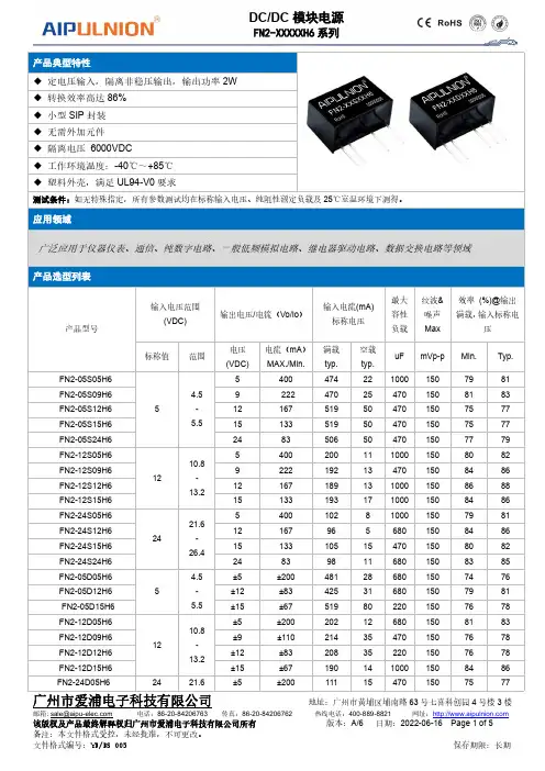
产品典型特性◆定电压输入,隔离非稳压输出,输出功率2W ◆转换效率高达86%◆小型SIP 封装◆无需外加元件◆隔离电压6000VDC◆工作环境温度:-40℃~+85℃◆塑料外壳,满足UL94-V0要求测试条件:如无特殊指定,所有参数测试均在标称输入电压、纯阻性额定负载及25℃室温环境下测得。
应用领域广泛应用于仪器仪表、通信、纯数字电路、一般低频模拟电路、继电器驱动电路、数据交换电路等领域产品选型列表产品型号输入电压范围(VDC)输出电压/电流(Vo/Io )输入电流(mA)标称电压最大容性负载纹波&噪声Max 效率(%)@输出满载,输入标称电压标称值范围电压(VDC)电流(mA )MAX./Min.满载typ.空载typ.uF mVp-p Min.Typ.FN2-05S05H654.5-5.554004742210001507981FN2-05S09H69222470254701508183FN2-05S12H612167519504701507577FN2-05S15H615133519504701507577FN2-05S24H62483506504701507779FN2-12S05H61210.8-13.254002001110001508082FN2-12S09H69222192134701508486FN2-12S12H6121671891310001508688FN2-12S15H6151331931710001508486FN2-24S05H62421.6-26.45400102810001507981FN2-24S12H6121679656801508486FN2-24S15H615133105154701508082FN2-24S24H6248398116801508385FN2-05D05H65 4.5-5.5±5±200481286801507476FN2-05D12H6±12±83425316801507981FN2-05D15H6±15±67519802201507678FN2-12D05H61210.8-13.2±5±200202126801508183FN2-12D09H6±9±110214354701507678FN2-12D12H6±12±83208352201507678FN2-12D15H6±15±671901410001508486FN2-24D05H62421.6±5±200111154701507577-26.4FN2-24D12H6±12±83104152201507880FN2-24D15H6±15±679810100015084861、“*”为开发中型号;2、为了确保该模块能够高效可靠的工作,使用时,其输出最小负载不能小于额定负载的10%。

i s c l ai m e r : T h i s d o c u m e n t a t i o n i s n o t i n t e n d e d a s a s u b s t i t u t e f o r a n d i s n o t t o b e u s e d f o r d e t e r m i n i n g s u i t a b i l i t y o r r e l i a b i l i t y o f t h e s e p r o d u c t s f o r s p e c i f i c u s e r a p p l i c a t i o n sMainRange of productModicon TM3Product or component typeAnalog input module Range compatibility Modicon M241Modicon M251Modicon M221Analogue input number 4Analogue input typeCurrent, analogue input range: 4...20 mACurrent, analogue input range: 0...20 mAVoltage, analogue input range: 0...10 VVoltage, analogue input range: - 10...10 V ComplementaryAnalogue input resolution11 bits + sign 12 bits Permissible continuous overload13 V voltage 40 mA current Input impedance<= 50 Ohm current >= 1 MOhm voltage LSB value 2.44 mV, analogue input: 0...10 V voltage4.88 mV, analogue input: - 10...10 V voltage4.88 µA, analogue input: 0...20 mA current3.91 µA, analogue input:4...20 mA currentConversion time 1 ms + 1 ms per channel + 1 controller cycle timeSampling duration <= 1 msAbsolute accuracy error +/- 0.1 % of full scale at 25 °C+/- 1 % of full scaleTemperature drift +/- 0.006 %FS/°CRepeat accuracy +/-0.5 %FSNon-linearity +/- 0.01 %FSCross talk <= 1 LSB[Us] rated supply voltage 24 V DCSupply voltage limits20.4...28.8 VSurge withstand 1 kV for power supply with common mode protection conforming to EN/IEC 61000-4-50.5 kV for power supply with differential mode protection conforming to EN/IEC 61000-4-51 kV for input with common mode protection conforming to EN/IEC 61000-4-5 Mounting support Top hat type TH35-15 rail conforming to IEC 60715Top hat type TH35-7.5 rail conforming to IEC 60715Plate or panel with fixing kitHeight90 mmDepth70 mmWidth23.6 mmProduct weight0.11 kgEnvironmentStandards EN/IEC 61010-2-201EN/IEC 61131-2Resistance to electrostatic discharge 4 kV on contact conforming to EN/IEC 61000-4-28 kV in air conforming to EN/IEC 61000-4-2Resistance to electromagnetic fields10 V/m at 80 MHz...1 GHz conforming to EN/IEC 61000-4-33 V/m at 1.4 GHz...2 GHz conforming to EN/IEC 61000-4-31 V/m at2 GHz...3 GHz conforming to EN/IEC 61000-4-3Resistance to magnetic fields30 A/m at 50...60 Hz conforming to EN/IEC 61000-4-8Resistance to fast transients 1 kV I/O conforming to EN/IEC 61000-4-4Resistance to conducted disturbances, induced by radio frequency fields 10 V at 0.15...80 MHz conforming to EN/IEC 61000-4-63 V at spot frequency (2, 3, 4, 6.2, 8.2, 12.6, 16.5, 18.8, 22, 25 MHz) conforming to Marine specification (LR, ABS, DNV, GL)Electromagnetic emission Radiated emissions, test level: 40 dBμV/m QP class A (10 m at 30...230 MHz) conforming to EN/IEC55011Radiated emissions, test level: 47 dBμV/m QP class A (10 m at 230 MHz...1 GHz) conforming to EN/IEC 55011Immunity to microbreaks10 msAmbient air temperature for operation-10...55 °C (horizontal installation)-10...35 °C (vertical installation)Ambient air temperature for storage-25...70 °CRelative humidity10...95 % without condensation in operation10...95 % without condensation in storageIP degree of protection IP20Pollution degree2Operating altitude0...2000 mStorage altitude0...3000 mVibration resistance 3.5 mm at 5...8.4 Hz with DIN rail mounting support3 gn at 8.4...150 Hz with DIN rail mounting supportShock resistance15 gn during 11 msOffer SustainabilitySustainable offer status Green Premium productRoHS (date code: YYWW)Compliant - since 1415 - Schneider Electric declaration of conformitySchneider Electric declaration of conformityREACh Reference not containing SVHC above the thresholdReference not containing SVHC above the threshold(*)8.5 mm/0.33 in when the clamp is pulled out.Incorrect Mounting(1)Install a mounting strip Mounting Hole LayoutWiring Diagram (Current / Voltage)(*)Type T fuse (1)Current/Voltage analog output device。
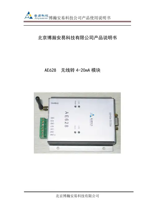
北京博瀚安易科技有限公司产品说明书AE628 无线转4-20mA模块北京博瀚安易科技有限公司一、概述无线转4-20mA模块,主要与本公司生产的无线温度变送器,无线压力变送器,无线流量计及无线密度仪,4-20mA转无线模块等无线发射端产品相配套的,将发射端的无线信号接收后,进行变送、转换、传输、运算,转换成需要的4-20mA信号。
与我司发射端的产品一起完成信号的传输工作。
二、功能特点●将我司的无线压力、温度、流量、液(物)位、密度等无线产品发射的无线数据接收,并转换成4-20mA输出;●无线输入●AO1、GND,AO2、GND为两路4-20mA输出;●通过RS232接口可以设定各种参数;RS232通道协议为MODBUS协议●RS232和4-20mA同步输出接收数据●体积小●性价比高●技术咨询QQ:583367295三、技术参数●供电电压:24VDC±10%●输入:无线信号●无线频率:433MHZ●无线增益:10dbm●无线距离:300米/500米(视距)●输出:两路4-20mA输出,RS232/RS485●负载能力:400欧●有线协议:MODBUS协议●型号:AE628●环境温度:-40℃~+85℃●环境湿度:5%~95%,无结露●振动:≤10g,f≤55Hz,振幅≤0.5mm●接地 :在电磁干扰大的地区,应将变送器和电缆屏蔽层良好接地四、安装及接线结构1、版面示意图2、接口说明2.1电源接口PGND :大地,可以不接。
VCC:24V+GND:24V-2.2 RS232/RS485接口RS232 接口/RS485接口2.3传感器接口AO1,GND :第1路接入。
AO1,为4-20mA的电流输入口。
GND为电流回路输出口。
AO2,GND :第2路接入。
AO2,为4-20mA的电流输入口。
GND为电流回路输出口。
2.3 运行指示2.3.1 Link1、Link2备用。
2.3.2 Power灯为电源指示灯,系统上电后,系统正常运行亮灯。
1. 简介
该文档是上海慧翰信息技术有限公司推出的蓝牙模块的硬件设计经验总结,适用于本公司的各个型号模块的硬件设计参考,敬请按型号区分要点。
如有何问题,请直接与本公司的工程师联系,您将会得到更详细的说明。
2. 天线设计
2.1 PIFA天线设计
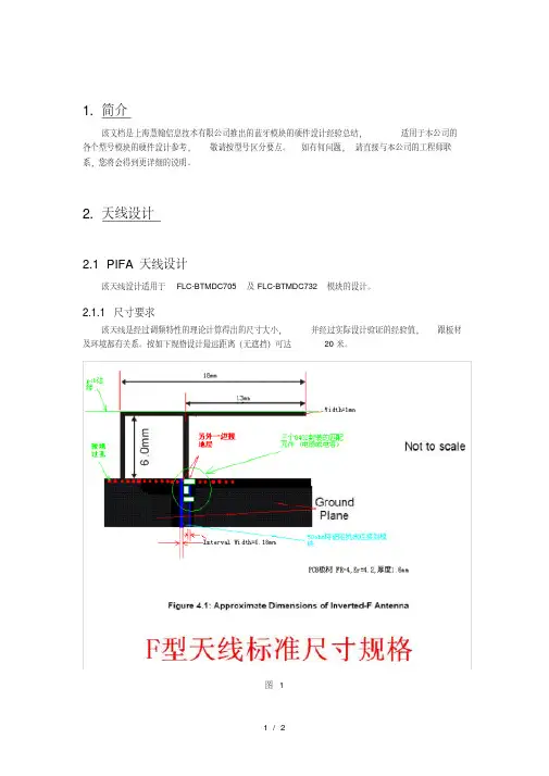
该天线设计适用于FLC-BTMDC705及FLC-BTMDC732模块的设计。
2.1.1 尺寸要求
该天线是经过调频特性的理论计算得出的尺寸大小,并经过实际设计验证的经验值,跟板材及环境都有关系。
按如下规格设计最远距离(无遮挡)可达20米。
图 1
2.1.2 布线要求
首先,建议将天线按尺寸设计成元件封装,方便摆放及后续项目设计,并可以防止拖动造成尺寸大小变化,而来回修改。
其次,该天线是与地线连接的,天线有效部分的周围及其下层(即
背面)不应用有元器、布线,更不应该铺铜,否则影响信号发射和接收,甚至无法正常工作。
第
三,该天线的接地点要求大面积接地,并多打过孔。
第四,该天线要求设计在PCB板的板边,尽量朝前面板,并要求周围避开铁质结构件。
2.1.3 板材要求
板材请选用:FR4,介电常数为 4.2
2.2 外引天线设计
请断开PIFA天线的连接电路,并用10pF的电容连接外引天线。
外引天线的线材要求采用
50欧高频屏敝电缆,并在尾部去掉3CM长的屏敝层。
线头的中间信号线焊接在天线输出端,而
屏敝铁线也应该焊在就近地线位置,该天线尾部应放置于前面板靠前位置或者引至铁壳之外。
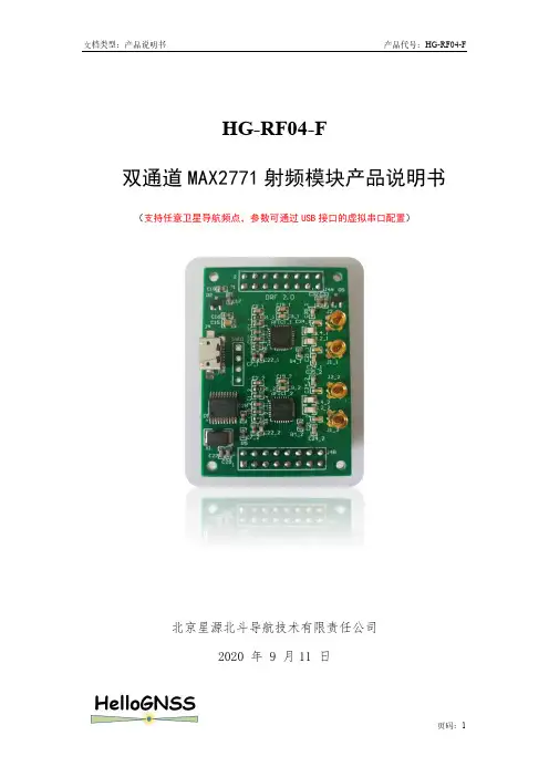
HG-RF04-F双通道MAX2771射频模块产品说明书(支持任意卫星导航频点,参数可通过USB接口的虚拟串口配置)北京星源北斗导航技术有限责任公司2020 年 9 月11 日更多详细信息请致电星源北斗咨询!公司地址:北京市海淀区温泉镇显龙山路19号北辰香麓雅庭A座218室电话:136****9930传真:************QQ:5024141邮箱:***************1 产品概述表1 产品价格表图1 HG-RF04-F 射频模块GNSS 射频模块HG-RF04-F 主要用于接收任意两个GNSS 频点的卫星信号,支持中频数字信号输出,每个射频支持两个独立的射频输入(同时只能使用一个输入口),分别对应L1附近的频点和L2/L5/B3附近的频点,提供3.3V馈电,射频输入加入的阻抗匹配可接信号模拟器、多频天线。
HG-RF04-F的MAX2771芯片可以独立配置(基于MicroUSB虚拟串口,通信协议和HG-AF04兼容),可支持I路和Q路信号同时输出。
2 主要参数HG-RF04-F基本特性如下:1.射频芯片:MAX2771×2,可支持任意GNSS频点,比如L1/L2/L5, B1C/ B1I/B2a/B3I。
2.TCXO:16.369MHz。
3.射频接口:MMCX×2,提供3.3V天线馈电,其中HI口表示L1附近频点输入,LO口表示L2/L5/B3附近频点输入,每个射频HI口和LO口同时只能有一个接天线。
4.中频接口:⚫时钟输出:GPSCLK1,GPSCLK2可选的采样时钟:ADC_CLKIN1,ADC_CLKIN2⚫I支路数据:I1、I0⚫Q支路数据:Q1、Q05.供电方式:+5V供电6.体积:50mm×35mm。
3 接口关系图2 HG-RF04-F对外接口图4 尺寸图图3 HG-RF04-F尺寸图(默认单位为mm)5 装箱清单1.HG-RF04-F射频模块1块;2.配套文档:HG-RF04-F使用说明书;6 服务条款1、半个月内如产品硬件有质量问题可免费更换;2、提供3个月QQ技术支持;3、本产品允许客户把产品提供的配置参数用于最终产品中,但不允许将本产品提供的配置参数和原理图提供给任何第三方。
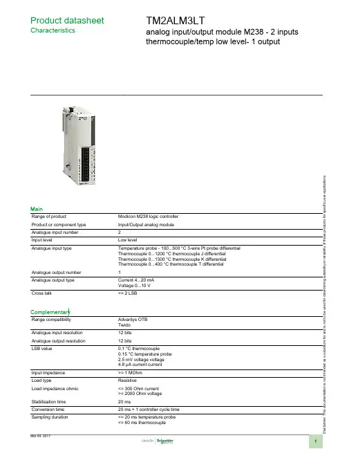
i s c l a i me r : T h i s d o c u m e n t a t i o n i s n o t i n t e n d e d a s a s u b s t i t u t ef o r a n d i s n o t t o b e u s e d f o r d e t e r m i n i ng s u i t a b i l i t y o r r e l i a b i l i t y o f th e s e p r o d u c t s f o r s p e ci f i c u s e r a p p l i c a t i o n sProduct datasheetCharacteristicsTM2ALM3LTanalog input/output module M238 - 2 inputs thermocouple/temp low level- 1 outputMainRange of productModicon M238 logic controller Product or component type Input/Output analog module Analogue input number 2Input levelLow levelAnalogue input typeTemperature probe - 100...500 °C 3-wire Pt probe differential Thermocouple 0...1200 °C thermocouple J differential Thermocouple 0...1300 °C thermocouple K differential Thermocouple 0...400 °C thermocouple T differential Analogue output number 1Analogue output type Current 4...20 mA Voltage 0...10 V Cross talk<= 2 LSBComplementaryRange compatibility Advantys OTB Twido Analogue input resolution 12 bits Analogue output resolution 12 bitsLSB value0.1 °C thermocouple0.15 °C temperature probe 2.5 mV voltage voltage 4.8 µA current current Input impedance >= 1 MOhm Load typeResistiveLoad impedance ohmic <= 300 Ohm current >= 2000 Ohm voltage Stabilisation time 20 msConversion time 20 ms + 1 controller cycle time Sampling duration<= 20 ms temperature probe <= 60 ms thermocoupleAcquisition period 60 ms per channel + 1 controller cycle time thermocouple 80 ms per channel + 1 controller cycle timeMeasurement error+/- 0.2 % of full scale - 100...500 °C 3-wire Pt probe 25 °C 0.2 % of full scale +/- 4 °C 0...1200 °C thermocouple J 25 °C 0.2 % of full scale +/- 4 °C 0...1300 °C thermocouple K 25 °C 0.2 % of full scale +/- 4 °C 0...400 °C thermocouple T 25 °C +/- 0.2 % of full scale 0...10 V 0...10 V 25 °C +/- 0.2 % of full scale 4...20 mA 4...20 mA 25 °C Temperature coefficient+/-0.006 %FS/°C - 100...500 °C 3-wire Pt probe +/-0.006 %FS/°C 0...1200 °C thermocouple J +/-0.006 %FS/°C 0...1300 °C thermocouple K +/-0.006 %FS/°C 0...400 °C thermocouple T +/-0.015 %FS/°C 0...10 V 0...10 V +/-0.015 %FS/°C 4...20 mA 4...20 mA Repeat accuracy +/-0.5 %FS input/output Non-linearity+/- 0.2 %FS temperature probe +/- 0.2 %FS thermocouple +/- 0.2 %FS current current +/- 0.2 %FS voltage voltage Output error +/- 1 %FS Output ripple <= 1 LSBTotal error+/-1 %FS temperature probe +/-1 %FS thermocouple +/-1 %FS current current +/-1 %FS voltage voltage Type of cableShielded cable Insulation between channel and internal logic Photocoupler SupplyExternal supply [Us] rated supply voltage 24 V DC Supply voltage limits 19.2...30 VElectrical connection 1 removable screw terminal block Current consumption 50 mA 24 V DC external 50 mA 5 V DC internal Product weight0.085 kgEnvironmentDielectric strength500 V between I/O channel500 V between the I/O and internal logic500 V between the I/O and the external supply circuit Width 23.5 mm Depth 70 mm Height90 mmOffer SustainabilitySustainable offer status Green Premium productRoHS (date code: YYWW)Compliant - since 1039 - Schneider Electric declaration of conformity Schneider Electric declaration of conformity REAChReference not containing SVHC above the threshold Reference not containing SVHC above the threshold Product environmental profileAvailableProduct environmental Product end of life instructionsAvailableProduct environmentalContractual warrantyWarranty period18 monthsDimensions DrawingsAnalog Mixed I/O Module (3-channel, Thermocouple/Temperature Probe/Voltage/Current)DimensionsNOTE: * 8.5 mm (0.33 in) when the clip-on lock is pulled out.DIN Rail MountingModule Mounting on a Panel Surface Mounting Hole LayoutWiring RequirementsCable Types and Wire Sizes for Removable Screw Terminal BlockAnalog Mixed I/O Module (3-channel, Thermocouple/Temperature Probe/Voltage/Current)Wiring Diagram Example2, 3 or 4 wires(1) 4 wires(2)Voltage/current preactuator (3)Thermocouple。
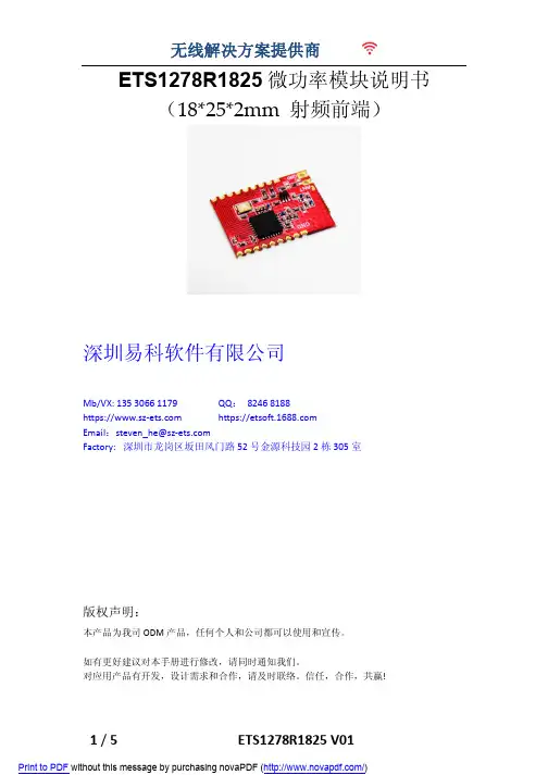
ETS1278R1825微功率模块说明书(18*25*2mm 射频前端)深圳易科软件有限公司Mb/VX:QQ:8246 8188https:// https://Email:Factory: 深圳市龙岗区坂田风门路52号金源科技园2栋305室版权声明:本产品为我司ODM产品,任何个人和公司都可以使用和宣传。
如有更好建议对本手册进行修改,请同时通知我们。
对应用产品有开发,设计需求和合作,请及时联络。
信任,合作,共赢!目录一、 模块介绍二、 产品特点三、 应用范围四、 尺寸与引脚定义五、 技术参数六、 模块应用注意事项七、 常见故障及排除方法八、 客户订制要求一、 模块介绍模块采用SX127x系列收发射频芯片,采用LORA扩频无线射频技术,数字处理技术,高抗干扰,高稳定性和高性价比。
用户只需通过模组提供的SPI数字接口,控制芯片内部寄存器,实现对SX127x 参数配置、无线数据收发等功能。
该模块具有尺寸小,灵敏度高,传输距离远,通讯速率高,延时小。
用户可以根据自己的要求来定制模块尺寸,输出功率,频率段等参数,或者直接将将模块布板到用户的PCB上,提升客户的产品水平和节省成本。
二、 产品特点微功率发射,最大输出20dbm,可通过设置控制发射功率。
工作频段:137MHZ-1020Mhz 等免申请频段,可根据用户的要求定制工作频段。
接收灵敏度最高达-148dBm@1200bps,在天线高度2米时,开阔地无干扰情况下可达3000米。
三、 应用范围无线排队设备,酒店电子门锁、生物识别门禁管理系统智能家居、家庭电器和灯光智能控制医疗和电子仪器仪表自动化控制智能教学设备、婴儿监护、医病房呼叫系统防盗报警,车辆防盗,智能卡,铁路机车远程检测水、电、煤气,暖气自动抄表收费系统或无功补偿及电网监测无线会议表决、打分系统,PDA终端、无线点菜系统LED屏无线传输文字,图片和无线控制,电子衡器、无线吊秤、车辆监测、老化设备检测,工业设备数据无线传输以及工业环境监测视频监控云台控制,门禁考勤读卡器气象/油井/水利设备信息采集以及自然环境检测资产管理和人员区域定位、物流供应链管理。
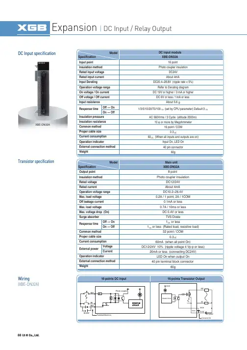
88DC Input specificationTransistor specificationWiring(XBE-DN32A)XBE-DN32ADC 6V or less / 1mA or less About 5.6AC 560Vrms / 3 Cycle (altitude 2000m)10or more by Megohmmeter 16 point / COM 0.360(When all inputs and outputs are on)Input On, LED On 1/3/5/10/20/70/100(set by CPU parameter) Default:3TVS Diode 1or less 1or less (Rated load, resistive load)32 point / COM 0.360mA (when all point On)DC12/24V 10% (ripple voltage 4 Vp-p or less)89SpecificationNames and FunctionsXBF-AD04AXBF-AD04CWiring 0~100001/16000(0~5V)-10000~10000(10V)APPLICSTION90SpecificationNames and Functions WiringXBF-DV04AXBF-DV04CXBF-DC04C911.25mV (DC 1~5V, 0~5V),2.5mV (DC 0~10V)5(DC 4~20mA, 0~20mA)SpecificationNames and FunctionsWiring XBF-AH04AAPPLICSTION92SpecificationWiring XBF-RD04ANames and Functions93SpecificationNames and Functions Wiring XBF-TC04SAPPLICSTION94-200.0 ~ 1300.00.0 ~ 500.0-200.0 ~ 1200.00.0 ~ 500.0-200.0 ~ 800100ppm/(0.01%/)Automatic compensation by RJC sensing2.0500ms/ 4 loopPID CONTROL, ON/OFF CONTROL20 minutes or above0.5 /min (30 /hour) or less16 point terminal (10 point terminal 1ea, 6 point terminal 1ea)Fixed: 64 points0.2% or less (25 , normal temperature,except -200~-100 for the T type)Insulation resistor: 500V DC, 10 M or aboveSpecificationXBF-TC04TT95-200.0 ~ 850.0 -200.0 ~ 600.0 0.2% or less (25 , normal temperature)100ppm/ (0.01%/ )500ms/ 4 loop PID CONTROL, ON/OFF CONTROL SpecificationXBF-TC04RT Insulation resistor: 500V DC, 10 M or aboveAPPLICSTION962 Channel (Insulation between Channels)5VDC 5%, (8 per 350load cell channel)Four-wire or Six-wire1/400000.0~6.00.125(when the rated output of the load cell is 0.0 ~ 1.0/ V)5V, DC 24Internal DC5V : 110External DC24V : 2805SpecificationXBF-LD02S0.01% or below (nonlinear accuracy, 25)Zero Drift: 0.25Gain Drift: 15ppm//DC500 V,10 M orabove Insulation Insulation Voltage Resistance(Internal Test Specifications)97APPLICSTIONSpecificationNames and Functions XBF-PD02ATerminal98Switching controlSpecificationXBF-PN08B-214748364.8~214748364.7()-21474.83648~21474.83647-214748364.8~214748364.7()-21474.83648~21474.83647-214748364.8~214748364.7()-21474.83648~21474.8364799APPLICSTIONNames and FunctionsTerminal100SpecificationXBF-HO02AXBF-HD02ANames and Functions101APPLICSTIONTerminal (XBF-HO02A)A+A-A+A-B+B-B+B-P 24VP 12VA phase differentiation input +A phase differentiation input -A phase differentiation input +A phase differentiation input -B phase differentiation input +B phase differentiation input -B phase differentiation input +B phase differentiation input -Terminal (XBF-HD02A)102Ethernet (XBL-EMTA)RAPIEnet (XBL-EIMT)XBL-C21AXBL-C41ARS-232C, RS-422 / 485103APPLICSTIONEthernet/IP (XBL-EIPT)Main unit scan 2 + Data receive time + Communication module scan XG5000 (setting station and high-speed link parameter block)Profibus-DP Module (XBL-PMEC, XBL-PSEA)104Thin Cable Terminal resistance ()125 kbps 250 kbpsCSMA/NBA Poll type Up to 64 (including master) MAC IDs (MAC Identifier)Insertion and removal of nod available in voltage On status Terminal resistance ()Master/Slave operation Data Processing unit XG5000 : High Speed Link Monitoring 110(5%), 1/2W Only available as Master Byte Rnet (XBL-RMEA)DeviceNet Module (XBL-DSEA)Trunk/drop line Power/Signal cable inside the identical network cable105APPLICSTIONCANopen Module (XBL-CMEA, XBL-CSEA)106Smart linkConnection cable Terminal board Option modules107APPLICSTION Program editing & Engineering software Windows-based easy operation Multi-PLC, Multi-programming support Various monitoring and diagnosis functions Convenient network settingExtended monitoring function for network system and communication modules Fast interface with CPU by effective network managementVarious built-in diagnosis, functions(CPU condition, Link conditon, Service condition, Frame monitoring)Trend monitor Special module monitor Ladder monitor Forced I/O Variable monitor Parameter setting Service conditionmonitoringNetwork scan Frame monitoring XGT PanelLink monitoringFast ethernetSmart I/O Other PLCOther netdevicsLS Inverter XG5000(Programming software)XG-PD (Network setting software)108Main SpecificationAluminum body frame, responsive touch screen.Easy-to-use Multi-touch, gesture, dual screen, portrait mode. Multi connected with 1Gbits 2ch. Ethernet between PC to PLC.Various interfaces : USB host /device, SD card, HDMI. High resolution : 1024 X 768IP66, UL type 4x, NEMA 4x standardsDate/Hour data, Logging/Alarm/Recipe data and nonvolatile device Approx. 3 years (Operating ambient temperature of 2577)109APPLICSTIONMain Specification1GHz 32bit RISC Embedded CPU 16,777,216 TFT color LCD128MB display data and1MB back-up memory Ethernet 1ch, RS-232C 2ch, RS-422/485 1ch USB host 3ch and device 1chSD memory card interfaceMain FunctionsPLC ladder monitoring (XGK/XBC PLC only)Web Server/Data Server Path through XP-Remote :Remote controlling and monitoringDate/Hour data, Logging/Alarm/Recipe data and nonvolatile device Approx. 3 years (Operating ambient temperature of 25)and USB memory driver is available)110Main SpecificationTFT LCD-applied wide typeLED Backlight adopted for enhanced contrast ratio and low-powerPLC Ladder monitoring function: Only XGK/XBC supports*Web Server* / Data Server* / Path-Through Function*Remote Viewer Function*Screen editor : XP-BuilderFunctions that support only the TTA modelDate/Hour data, Logging/Alarm/Recipe data and nonvolatile deviceApprox. 3 years (Operating ambient temperature of 50)Time error Approx. 3 sec/1day(Operating ambient temperature of 25)1 channel, USB 2.0 Host (mouse, keyboard, printer and USB memory driver is available)4.6W7.2W 6.5W10W12810232165.0132.536.1165.0132.536.1156.0123.5208.0154.044.4192.0138.0276.0218.044.4260.0202.01 channel, IEEE802.1a, 10Base-T/100Base-TX111APPLICSTIONGraphic type XP30/XP40/XP50/XP70/XP80/XP90High and vivid distinction with 65,536 colors High quality raster and vector symbolsVarious BMP JPG GIF graphic file support: BMP, JPG, GIF, WMF, etc Simple animation effects: animated GIF 10/100BASE-T Ethernet interface Convenient and easy screen editingStrengthened data management: Logging, Recipe, and Alarm Read function of a controller’s state information: Monitoring and maintenanceMulti-lingual display: up to 8 languagesOffline and concurrent simulation with XG5000 Easy to change the address of the graphic objects: Tag function with XGT PanelUSB host for peripheral devices: USB Drive, Mouse, keyboard, printer, etcSufficient memory for screen data: 10MB112Text type XP10Screen: 192 64 Graphic STN LCDSystem RAM: 1000 wordsFlash memory: Program/Parameter back upCommunication: Half-duplex comm.- Baud rate: 1200~115200 bps - Master/slave setting available- RS-232C/RS-485 2 CH separate to usePower reguirements - 24 V input or 5 V direct input by LS PLC Various function key - ESC, ALM, SET, ENT, F1~F4, Arrow keys Panel Editor - Easy programming and H/W settingKey to control PLC device and screen ESC key Alarm historyData input and Screen change PLC data setting Enter keyDC24V input terminalRS-232C port to download a project Brightness adjustment RS-422 port115,200bps12 Keys (F1~F4, ESC, ALM, ,113APPLICSTIONProduct list114Product list。
声明Copyright ©2008深圳市合信自动化技术有限公司版权所有,保留一切权利。
非经本公司书面许可,任何单位和个人不得擅自摘抄、复制本书内容的部分或全部,并不得以任何形式传播。
CTS7 231-7HF32 电流输入型PID温控模块用户手册目录一、技术参数 (1)二、PID地址与参数配置 (2)1、PID地址计算公式 (2)2、PID参数输出部分(模块到CPU) (2)3、PID参数输入部分(CPU到模块) (3)4、正向脉冲输出地址 (3)5、负向脉冲输出地址 (4)6、应用举例 (4)三、端子连接 (5)四、DIP开关配置 (5)TrustPLC®专门为温度控制应用而量身订制的PID温控扩展模块,内置PID温控算法,用户无需编程即可实现复杂的闭环温度控制。
而且由于减轻了CPU的运算负担,控制速度更快,效果更出色。
一、技术参数231-7HF 、231-7HD 电流输入温控PID 模块技术规格订货数据规格参数订货号EM231,8AI×PID CTS7 231-7HF适用于连接到CTS7-224/226/PSC226 S7-224/226插入式I / O 端子不是输入数目8,模拟量输入范围/ 输入阻抗电流型输入电压输入端的允许输入电压,最大30 V DC电隔离是•现场侧-逻辑500 V AC•现场侧-直流24 V 500 V AC•直流24 V-逻辑500 V AC更新时间825 ms (所有通道)测量原理SIGMA-DELTA分辨率15 bit + 符号•温度0.1 ℃/ 0.1 ℉噪声频率上的噪声抑制85 dB•对噪声频率50 / 60 / 400 Hz共模电压120 V AC共模抑制,最小120 dB at 120 V AC基本误差0.1% FS (电流)再现性0.05% FS诊断程序LED :EXTF,SF电缆长度,最大100 m —传感器电缆环路电阻,最大10 Ω电流消耗•总线(5 V DC)30 mA•L+ 37 mA功率损耗 1.8 W尺寸(W x H x D),mm 120.5 x 80 x 62重量210 gPID 特性PID算法PID+FUZZY参数自调整采样时间1秒输出最小脉宽10msPID类型P、PI、PD、PID型PID输出类型模拟量或PWM脉宽控制PID输出极性双极或单极二、PID地址与参数配置1、PID地址计算公式地址名称计算公式备注PID参数地址A=(2048+S*256)+16*C PID正向脉冲输出地址X=(2048+S*256)+12 PID负向脉冲输出地址Y=(2048+S*256)+13 S为模块所在的槽号(范围0~6)C为通道号 231-7HF为0~72、PID参数输出部分(模块到PLC)内容地址数值范围实际值实际温度VW A 0---13000 0---1300度(根据用户设定的Range参数而定,默认是1300)状态字VW A+2PID模拟量输出VW A+4 双极:-32000~+32000单极:0~+320003、PID参数输入部分(PLC到模块)设定温度VW A+128 0---13000 0---1300度控制字节VB A+130 位为“0”时位为“1”时V (A+130).0 PID不运行,没输出PID运行V (A+130).1 积分一直起作用,比例积分分离及比例系数自动调整系数Kp不自动调整V (A+130).2 PID单极输出PID双极输出,具有加热和冷却功能V (A+130).3 无作用无作用V (A+130).4 积分起作用积分不起作用V (A+130).5 微分起作用微分不起作用实际温度值不滤波V (A+130).6 实际温度值滤波,抗干抗更强VW A+132 1-255 1-255秒PID脉冲输出周期设定Kp(比例系数) VW A+134 0—9999 0—999.9Ti(积分时间)VW A+136 0—3600 0—3600秒Td(微分时间) VW A+138 0—3600 0—3600秒Range(量程范围) VW A+140 0--13000 0—1300度4、PID正向脉冲输出地址的计算:X=(2048+S*256)+120通道脉冲输出V x.01通道脉冲输出V x.12通道脉冲输出V x.23通道脉冲输出V x.34通道脉冲输出V x.45通道脉冲输出V x.56通道脉冲输出V x.67通道脉冲输出V x.75、PID负向脉冲输出地址的计算:Y=(2048+S*256)+130通道脉冲输出V y.01通道脉冲输出V y.12通道脉冲输出V y.23通道脉冲输出V y.34通道脉冲输出V y.45通道脉冲输出V y.56通道脉冲输出V y.67通道脉冲输出V y.76、应用例子:计算第二个扩展模块上的231-7HF的最后一个PID回路的地址,Kp=1200,Ti=360,Td=50脉冲输出周期设定=2s,第二个模块最后一个通道,所以:S=1,C=7A地址A=2048+1*256+16*7=2416X地址X=2048+1*256+12=2316Y地址y=2048+1*256+13=2317DB BLOCK的参数块如下:// S=1, C=7VW2544 //设定温度VB2546 //控制字(PID使能、参数自调整、双极输出VW2548 //脉冲输出周期VW2550 //Kp比例系数VW2552 //Ti积分时间(秒)VW2554 //Td微分时间(秒)VW2556 //量程范围1300度(默认值)VW2416 //实际温度VW2418 //状态字VW2420 //PID模拟量输出三、端子接线图四、DIP开关配置Sw1 Sw2 Sw3 Sw4 Sw5 Sw6 量程分辨率ON ON OFF OFF OFF OFF 0—20mA 0.1℃/F ON ON ON OFF OFF OFF 4—20mA 0.1℃/F。
HS12864-18液晶显示模块使用说明书感谢您关注和使用我们的液晶产品。
如果您在使用中有任何疑问,请拨打我们的客户服务热线寻求技术支持和获取相关资料,我们竭诚为您服务。
您可以登录我们的网站了解最新产品信息。
或者您可以在我公司网站的留言簿栏目留下您宝贵的意见。
深圳汉昇实业有限公司SHENZHEN HANSHENG INDUSTRIAL CO.,LTD地址:深圳市南山区西丽镇官龙工业村东区18栋5楼邮编:518055公司主页:联系电话:传真:一、 概述HS12864-18使用KS0108(或其兼容芯片)作为控制器,适配M6800系列时序,具有8位标准数据总线。
可显示各种字符及图形。
每个KS0108拥有64×64位(512字节)的显示RAM,HS12864-18显示屏上的64×64点,显示RAM中的数据直接作为显示驱动信号。
HS12864-18具有操作指令简单,低功耗的特点。
HS12864-18采用COB工艺制作。
二、 外形结构1. 外形图2. 主要外形尺寸项 目 标 准 尺 寸 单 位模 块 体 积 75.0×54.7×12.5(max) mm视 域 60.0×32.6 mm行 列 点 阵 数 128×64 dots点 距 离 0.43×0.43 mm点 大 小 0.40×0.40 mm三、 硬件说明1. 接口定义管脚符号电平功能描述1 VDD 5.0V 供电电源,5.0V2 VSS 0V 电源地3 V0 负压 LCD驱动电压输入端(对比度调节)4-11 DB0~DB7H/L 数据线12 CS1 L 片选信号1,低有效,对应左半屏64×64点13 CS2 L 片选信号2,低有效,对应右半屏64×64点14 /RST H/L 复位信号,低有效15 R/W H/L 读/写信号高:读操作低:写操作16 RS H/L 寄存器选择端高:数据寄存器低:命令寄存器17 E H,H->L 使能信号18 V out 负压负压输出端19 LEDA 5.0V 背光正极20 LEDK 0V 背光负极2. 最大工作范围(1)逻辑工作电压(Vdd):4.5~5.5V(2)电源地(VSS): 0V(3)工作温度(Ta): -20~70℃(宽温)(4)存储温度(Tstg): -30~80℃3. 电气特性(测试条件 Ta=25,Vdd=5.0+/-0.25V)(1)输入高电平(Vih): 3.5Vmin(2)输入低电平(Vil): 0.55Vmax(3)输出高电平(Voh): 3.75Vmin(4)输出低电平(Vol): 1.0Vmax(5)工作电流: 8.0mAmax (注:不含背光电流)4. 原理简图VSS V0CS1CS25. HS12864-18的对比度调节HS12864-18上有负压电路,生成的负压由Vout 脚输出,加过用户主板返回到液晶模块接口的V0端,由此调节对比度。
摘要为了更好地满足计算过程中准确性、精确性、快速性和宽频带的要求,本文提出基于DSP的智能电表的设计原理和实现技术。
本方案主要由检测电路、专用电能计量芯片ATT7022、STC12单片机、128×64液晶显示、按键、RS485通信、红外通信以及电源部分组成。
电路中的电流(电压)信号经过电流(电压)互感器,强电信号转换为安全的弱电信号,通过ATT7022把计量数据传给单片机,由单片机控制128×64液晶显示,另设按键可选择显示测量数据,并扩展RS485和红外线通信功能。
因为ATT7022具有极高的精度,能够达到1级测量精度要求,由于互感器铁芯趋于饱和,当电力线路出现过电压或过电流时,其输出不会成正比的增加,能保护测量仪表设备。
关键词:精确计量、ATT7022、STC12C5410、通信、显示、按键AbstractTo satisfy even more the veracity and the precision and the celerity and the Broad Band.we present a new theory and a new technology to contriveall intelligent power-converter(ipc) based on dsp. This scheme mainly consists of Detection circuit, Special energy metering ATT7022 chips,STC12,128 * 64 LCD display,key,RS485 communication,Infrared communication and power..The current in the circuit by current signal (voltage transformer, high voltage (voltage) signals are converted to electricity signal, the safety ATT7022 through the measurement data to SCM by single-chip microcomputer control, 128 * 64 LCD display, and buttons can choose to display measured data, and expand RS485 and infrared communication function. Because of the high precision, ATT7022 can reach 1 level measurement accuracy requirement, and because of transformer core tend to saturation, when power line voltage or current appeared, the output will increase, the proportional to the measuring equipment to protect.Keywords: accurate measurement ATT7022 STC12C5410communication display key-press绪论研究意义针对目前三相功率表存在的局限性,为了很好的满足计算过程中准确性、精确性、快速性和宽频带的要求,应用了DSP技术,引入了DSP芯片,即它是利用DSP的强大功能,来实现高速运算,从而实现适时精确计算的功能;在需要对结果数据进行处理,以及键盘、显示、外部接口的控制与管理时,由于这一部分任务对时间要求不高,且需要大量的CPU总线资源,不适合用DSP来完成,因此,考虑选用一片普通单片CPU来负责整个系统的管理及数据再处理的工作。
文件编号:密级:无版本:Z1.0《LH-108型车载终端》用户手册1.接收灵敏度: -110dBm2.发射功率: < 0.8W3.通讯速率: 9.6K4.发射频率稳定度:±2ppm5.接口标准: RS-232C2.3、整机参数1.体积: 100mm*75mm*27mm(长*宽*高)2.颜色: 银灰色.3.重量: 600G4.输入电压范围: 9V~30V 直流5.工作电流: ±60mA? @12V6.工作环境: -20~+70℃7.后备电池使用时间: 2小时8.通讯方式:SMS、TCP、UDP三、功能详细说明3.1查询功能注:点火时回传位置信息的时间间隔最小单位为3秒。
3.2.3、ACC关时定时回传位置信息时间间隔熄火时回传位置信息的时间间隔,终端出厂默认5分钟。
注:点火时回传位置信息的时间间隔最小单位为1分钟。
3.2.4、超速报警设置设置超速报警值后,如该车辆速度超过设定值且时间持续10秒以上,车载终端自动对监控中心发出超速报警。
终端出厂默认为关闭状态(即设置值为0)。
设置的门阀值要大于10km/h才有效。
3.2.5、停车超时报警设置设置超时报警门阀值后,当车辆的行驶速度为0时,且时间持续超过超时报警门阀值,则产生超时报警。
超时报警门阀值设置时,要设置大于1分钟以上的门阀值才有效。
终端出厂默认为关闭状态(即设置值为0)3.2.6、设置/取消/查询电子围栏(只支持1个电子围栏)报警方式:第一次产生报警时,立即上传一条信息。
以后则根据定时回传时间间隔上传。
取消报警方式:下发取消报警指令且车辆行驶速度小于超速报警门阀值。
下发取消报警指令且关闭超速报警。
3.4.2、停车超时报警设置超时报警门阀值后,当车辆的行驶速度为0时,且时间持续超过超时报警门阀值,则产生超时报警。
超时报警标志位包含在位置信息里。
报警方式:第一次产生报警时,立即上传一条信息。
以后则根据定时回传时间间隔上传。
取消报警方式:下发取消报报警指令且车辆行驶速度大于0。
用户手册HCP系列可编程直流电源HSW系列可编程直流电源HSP系列可编程直流电源HLR系列可编程直流电源深圳市恒惠源电子有限公司公司名称:深圳市恒惠源电子有限公司东莞市倍达仪器有限公司公司地址:深圳市龙华区大浪街道华荣路荣泰大厦1013室工厂地址:东莞市东城街道牛山社区创富工业园C栋3楼电话:*************手机:158****8208(微信)/189****4820传真:*************Q Q:29620552邮箱:**************目录安全概要 (III)第一章概述 (1)1.1 HCP系列介绍 (1)1.2HCP系列特点 (1)1.3 HSW系列介绍 (2)1.4HSW系列特点 (2)1.5 HSP系列介绍 (3)1.6HSP系列特点 (3)1.7 HLR系列介绍 (4)1.8HLR系列特点 (4)1.9 前后面板 (5)1.10 键盘描述 (6)1.11 用户界面 (7)1.12 首次使用 (8)1.12.1连接电源 (8)1.12.2通电检查 (8)1.12.3输出检查 (8)1.13 显示模式 (9)第二章操作说明 (10)2.1 数据输入 (10)2.2 恒压输出 (11)2.3 恒流输出 (12)2.4 过压/过流保护 (13)2.4.1 O.V.P (13)2.4.2 O.C.P (13)2.5 定时输出 (14)2.6 存储与调用 (17)2.7 系统功能 (19)2.7.1 接口设置 (19)2.7.2 触发设置 (20)2.7.3 系统设置 (20)2.7.4 恢复出厂设置 (22)2.8 辅助功能 (23)2.8.1 电池曲线充电功能 (23)2.9 远程感应功能 (25)2.10 远程感应功能设置(仅适用于HCP系列) (25)2.10.1使用本地感应 (25)2.10.2使用远程感应 (26)2.11 模拟量控制功能 (27)第三章远程控制 (28)3.1 RS232接口设置 (28)3.1.1 连接方式 (28)3.1.2 通讯设定 (28)3.2 RS485接口设置 (29)3.2.1 连接方式 (29)3.2.2 通讯设定 (29)3.3 SCPI编程指令集 (29)3.4 MODBUS编程指令集 (29)第四章维护 (30)4.1 定期检查 (30)4.2 保险丝的替换 (30)第五章性能指标 (31)5.1 HCP系列技术参数 (31)5.2 HSW系列技术参数 (32)5.3 HSP系列技术参数 (33)5.4 HLR系列技术参数 (35)性能指标若有变动恕不另作声明。
1981OPERATING MANUAL300 WATT ELECTRONIC LOAD MODULEAgilent Model 60502BFOR MODULES WITH SERIAL NUMBERS:3118A-00101 AND ABOVEAgilent Part No. 60502-90008 Printed in U.S.A. Microfiche No. 60502-90009 June, 1991DECLARATION OF CONFORMITYaccording to ISO/IEC Guide 22 and EN 45014TechnologiesManufacturer’s Name: AgilentManufacturer’s Address: New Jersey Division140 Green Pond RoadRockaway, NJ 07866 U.S.A.declares that the productProduct Name:Load mainframe and modulesModel Number(s):Agilent 6050A, 6051A mainframes with modulesAgilent 60501A/B, 60502A/B, 60503A/B, 60504A/B, 60507A/B conform(s) to the following Product Specifications:Safety:IEC 348:1978 / HD401 S1:19811EMC:CISPR 11:1990 / EN 55011:1991 - Group 1, Class BIEC 801-2:1991 / EN 50082-1:1992 - 4kV CD, 8 kV ADIEC 801-3:1984 / EN 50082-1:1992 - 3 V/mIEC 801-4:1988 / EN 50082-1:1992 - 0.5 kV Sig. Lines, 1 kVPower Lines Supplementary Information:The product herewith complies with the requirements of the Low Voltage Directive 73/23/EEC and the EMC Directive 89/336/EEC and carries the CE-marking accordingly.Note 1: The product family was introduced prior to 12/93New Jersey January 1997300-Watt ModuleAbout This ManualThis manual provides information for the Agilent 60502B 300-Watt Electronic Load Module. It is designed as a supplement to the Agilent 6050A/6051A Multiple Input Mainframe Electronic Load Operating Manual (part number 06050-90001). Four tables provide the following module-specific information:Table 60502-1 lists both the specifications and supplemental characteristics of the module. Specifications indicate warranted performance in the 25 °C ± 5 °C region of the total temperature range (0 to 55° C). Supplemental characteristics indicate non-warranted, typical performance and are intended to provide additional information by describing performance that has been determined by design or type testing.Table 60502-2 lists the ranges that can be programmed in constant current, constant resistance, and constant voltage modes. It shows the maximum and minimum programming values for each range. Refer to this table when programming the module locally as described in Chapter 4, or remotely as described in Chapter 5 of the operating manual.Table 60502-3 gives the factory default values of the module. Unless you have saved your own wake-up settings, the module will be set to the factory default values whenever power is applied. See Chapter 4 in the operating manual.Table 60502-4 provides calibration information for the module. This information is needed to perform the annual calibration procedure described in Chapter 6 of the operating manual.Module Installation and OperationExcept for the module-specific information in this manual, all installation, operation, and calibration instructions are given in the Mainframe Operating Manual. The Agilent Electronic Load Family Programming Reference Manual (part number 06060-90005) contains complete programming details that apply to all Electronic Load models.Note:The following information in Chapter 2 of the Mainframe Operating Manual does not apply to electronic load modules with the serial numbers listed on the title page of this manual: The section titled "ExtendedPower Operation", and the section titled "Extended Power Limit". Also for these modules, change the 3-second delay referred to under "Nominal Power Limit" to 50 milliseconds.Items SuppliedIn addition to this manual, a 10-pin connector plug is also shipped with your Electronic Load module. Refer to Chapter 3 in the operating manual for more information.12Table 60502-1. Specification and Supplemental CharacteristicsSPECIFICATIONS DC Input Rating:Current: 0 to 60 AVoltage : 3 V to 60 V (minimum dc operation from 0 to 2 V for 0 to 60 A)Power: 300 W at 40 °C (derated to 225 W at 55 °C)A. OPERATING CHARACTERISTICSB. DERATED CURRENT DETAIL Constant Current Mode:Ranges:0 to 6 A; and 0 to 60 AAccuracy: (after 30 second wait): ± 0.1% ± 75 mA (both ranges)Resolution: 1.6 mA (6 A range); 16 mA (60 A range)Regulation:10 mA (both ranges)Temperature Coefficient:100 ppm/°C ± 5 mA/°C (both ranges)Constant Resistance Mode:Ranges:0.033 to 1 Ω; 1 Ω to 1 k Ω; and 10 Ω to 10 k ΩAccuracy:± 0.8% ± 8 m Ω with ≥ 6 A at input (1 Ω range);± 0.3% ± 8 mS with ≥ 6 V at input (1 k Ω and 10 k Ω ranges)Resolution:0.27 m Ω (1 Ω range); 0.27 mS (1 k Ω range); 0.027 mS (10 k Ω range)Regulation:10 mV with remote sensing (1 Ω range); 10 mA (1 k and 10 k Ω ranges)Temperature Coefficient:800 ppm/°C ± 0.4 m Ω/°C (1 Ω range);300ppm/°C ± 0.6 mS/°C (1 k and 10 k Ω ranges)Constant Voltage Mode:Range:0 to 60 VAccuracy:± 0.1% ± 50 mV Resolution: 16 mVRegulation:10 mV (remote sense); 40 mV (local sense)Temperature Coefficient:100 ppm/°C ± 5 mV/°CTransient Operation:Continuous ModeFrequency Range:0.25 Hz to 10 kHzFrequency Resolution: 4%Frequency Accuracy: 3%Duty Cycle Range:3% to 97% (0.25 Hz to 1 kHz); 6% to 94% (1 kHz to 10 kHz)Duty Cycle Resolution: 4%Duty Cycle Accuracy:6% of setting ± 2%Pulsed Modeµs ± 3% minimum; 4 s ± 3% maximumPulse Width: 50Transient Current Level (0 to 6 A and 0 to 60 A ranges):Resolution:26 mA (6 A range); 260 mA (60 A range)Accuracy:± 0.1% ± 80 mA (6 A range); ± 0.1% ± 350 mA (60 A range)Temperature Coefficient:100 ppm/°C ± 7 mA/°CTransient Resistance Level (0.033 to 1 Ω, 1 Ω to 1 kΩ, and 10 Ω to 10 kΩ ranges):Resolution: 4.3 mΩ (1 Ω range); 4.3 mS (1 kΩ range); 0.4 mS (10 kΩ range) Accuracy:± 0.8% + 8 mΩ with > 6 A at input (1 Ω range)± 0. 3% + 10 mS with ≥ 6 V at input (1 kΩ range)± 0.3% + 7 mS with ≥ 6 V at input (10 kΩ range)Transient Voltage Level (0 to 60 V):mVResolution: 260Accuracy: ± 0.1% ± 300 mVppm/°C ± 5 mV/°CTemperature Coefficient: 150Current Readback:Resolution:17 mA (via GPIB); 20 mA (front panel)Accuracy:(after 30 minute wait): ± 0.05% ± 65 mA°C ± 5 mA/ °CTemperature Coefficient: 50ppm/Voltage Readback:Resolution:17 mV (via GPIB); 20 mV (front panel)Accuracy:± 0.05% ± 45 mVTemperature Coefficient:50 ppm/°C ± 1.2 mV/°CMaximum Readback Capability:65 to 70 V (typical)Power Readback:Accuracy: ± 0.2% ± 4 W3External Analog Programming 0 to 10 V (dc or ac):Bandwidth:10 kHz (3 db frequency)Accuracy:± 4.5% ± 75 mA (0 to 6 A range)± 4.5% ± 250 mA (0 to 60 A range)± 0.8% ± 200 mV (0 to 60 V range)Temperature Coefficient:100 ppm/°C ± 6 mA/°C (current ranges)100 ppm/°C ± 1 mV/°C (voltage range)External Current Monitor (0 to 10 V):Accuracy:± 0.4% ± 85 mA (referenced to analog common)Temperature Coefficient:50 ppm/°C ± 6 mA/°CExternal Voltage Monitor (0 to 10 V):Accuracy:± 0.25% ± 40 mV (referenced to analog common)°C ± 0.2 mV/ °CTemperature Coefficient: 50ppm/Remote Sensing: 5 Vdc maximum between sense and input binding postsMaximum Input Levels:Current:61.2 A (programmable to lower limits)Voltage:75 VMinimum Operating Voltage: 2 V (derated to 0 V at 0 A)PARD (20 Hz to 10 MHz noise):Current: 4 mA rms/40 mA p-pVoltage: 6 mV rmsDC Isolation Voltage:± 240 Vdc between + or - input binding post and chassis groundDigital Inputs:V lo:0.9 V maximum at I lo = -1 mAV hi 3.15 V minimum (pull-up resistor on input)Digital Outputs:V lo:0.72 V maximum at I lo = 1 mAV hi: 4.4 V minimum at I lo - 20 µASUPPLEMENTAL CHARACTERISTICSProgrammable Slew Rate (For any given input transition, the time required will be either the total slew time or a minimum transition time, whichever is longer. The minimum transition time increases when operating with input currents under 1 A. The following are typical values; ± 25% tolerance):4Current Slew Rate:*Rate #60 A Range Step 6 A Range Step Transition Time1 1 A/ms 0.1 A/s 8.0 ms2 2.5 A/ms 0.25 A/s 3.2 ms3 5 A/ms 0.5 A/s 1.6 ms4 10 A/ms 1 A/ms 800 µs5 25 A/ms 2.5 A/ms 320 µs6 50 A/ms 5 A/ms 160 µs7 0.1 A/µs 10 A/ms 80 µs8 0.25 A/µs 25 A/ms 32 µs9 0.5 A/µs 50 A/ms 16 µs10 1 A/µs 0.1 A/µs 12 µs11 2.5 A/µs 0.25 A/µs 12 µs12 5 A/µs 0.5 A/µs 12 µs*AC performance specified from 3 to 60 V.Voltage Slew Rate:Rate #Voltage Range Step Transition Time*1 1 V/ms 8.0 ms2 2.5 V/ms 3.2 ms3 5 V/ms 1.6 ms4 10 V/ms 800 µs5 25 V/ms 320 µs6 50 V/ms 160 µs7 0.1 V/µs 85 µs8 0.25 V/µs 85 µS9 0.5 V/µs 85 µS*Transition time based on low capacitance current source.Resistance Slew Rate (1 Ω range): Uses the value programmed for voltage slew rate.Resistance Slew Rate (1 k and 10 kΩ ranges): Uses the value programmed for current slew rate. Transient Current Overshoot (When programmed from 0A):Range Transient Current Level Current Slew Rate Overshoot*60 A6-60 A All slew rates03 A 1 A/µs to 5 A/µs1%3 A 1 A/µs to 0.5 A/µs06 A 6 A All slew rates03 A0.25 A/µs to 0.5 A/µs1%3 A0.1 A/ms to 0.1 A/µs0*Overshoot may be higher during the first five seconds of programming if unit has been operating at full current. Overshoot values assume a total inductance of lµH, or less, in the load leads connected to the D.U.T.56Source Turn-On Current Overshoot: Less than 10% of final value (in CC and CR modes when connected to power supplies with voltage rise times of greater than 500µs).Programmable Short Circuit: 0.033 Ω (0.002 Ω typical)Programmable Open Circuit: 20 k Ω (typical)Drift Stability (over an 8 hour interval):Current:± 0.03% ± 10 mA Voltage:± 0.01% ± 10 mVReverse Current Capacity: 100 A when unit is on; 40 A when unit is off Weight:3.2 kg (7 lbs.)Table 60502-2. Programming RangesFunctionFront Panel Front Panel HPSL CommandRange of ValuesKey Display (Short Form)Constant Current Set RangeCURR value"CURR value"Low Range0 to 6 A High Range 0 to 60 ASet Slew Rate(shift)C:TLV value"CURR:TLEV value"same as main level *Set Triggered Level "CURR:TRIG value"same as main levelConstant Resistance Set RangeRES value"RES value"Low Range 0 to 1 Ω Middle Range 1 Ω to 1 k Ω High Range 10 Ω to 10 k ΩSet Slew Rate(shift)R:TLV value"RES:TLEV value"same as main level *Set Triggered Level "RES:TRIG value"same as main levelConstant Voltage Set Main LevelV:SLW value"VOLT:SLEW value"0.001 to 0.5 (V/µs)Set Transient Level7Table 60502-2. Programming Ranges (continued)FunctionFront Panel Front Panel HPSL CommandRange of ValuesKey Display (Short Form)Transient Operation Set FrequencyDCYCLE value"TRAN:DCYC value"3-97% (0.25 Hz-1 kHz)6-94% (1 kHz-10 kHz)*Set Pulse Width"TRAN:TWID value"0.00005 to 4 s Trigger Operation *Set Trigger Period "TRIG:TIM value"0.000008 to 4 s Current Protection *Set Current Level "CURR:PROT value"0 to 61.2 A *Set Delay Time"CURR:PROT:DEL value"0 to 60 s*Can only be programmed remotely via the GPIB.Table 60502-3. Factory Default SettingsFunction Settings Function Setting CURR level 0 A Mode (CC, CR, CV)CC CURR transient level 0 A Input (on/off)on *CURR slew rate 1 A/µs Short (on/off)off CURR range 60 ATransient operation (on/off)off *CURR protection (on/off)off ***TRAN mode continuous **CURR protection level 61.2 A (continuous, pulse, toggle)**CURR protection delay 15 s TRAN frequency1 kHz TRAN duty cycle50%RES level 1 k Ω**TRAN pulse width 0.5 ms RES transient level 1 k ΩRES range 1 k Ω**TRIG source hold (bus, external, hold, timer, line)VOLT level 60 V **TRIG period 0.001 s VOLT transient level 60 V **PORT0 output (on/off)off (logic 0)VOLT slew rate 5 V/µs**CAL mode (on/off)offThe *RST command resets the CURR slew rate to 5 A/µs, not to the factory default.**Can only be programmed remotely via the GPIB.***Continuous transient mode is the only mode available at the front panel. Pulsed, toggled, and continuous modes can all be programmed remotely via the GPIB.Table 60502-4. Calibration InformationRanges and Calibration Points Variables VariablesValuePower SupplySettingsCurrentShuntHigh Current Range Hi_curr_rng60 5 V/61 A100 A High Current Offset Hi_curr_offset0.0282Low Current Range Lo_curr_rng6 5 V/10 A15 A Low Current Offset Lo_curr_offset0.0197Voltage Range N/A N/A61 V/5 A N/A Voltage Hi point Volt_hipt60Voltage Lo point Volt_lopt 2.7Low Resistance Range Lo_res_rng115 V/10.9 A15 A Low Resistance Hi point Lo_res_hipt1Low Resistance Lo point Lo_res_lopt0.04Middle Resistance Range Mid_res_rng1010.9 V/15 A15 A Middle Resistance Hi point Mid_res_hipt30Middle Resistance Lo point Mid_res_lopt1High Resistance Range Hi_res_rng100160 V/6 A15 A High Resistance Hi point Hi_res_hipt120High Resistance Lo point Hi_res_lopt128Agilent Sales and Support OfficeFor more information about Agilent Technologies test and measurement products, applications, services, and for a current sales office listing, visit our web site: /find/tmdirYou can also contact one of the following centers and ask for a test and measurement sales representative.United States:Agilent TechnologiesTest and Measurement Call Center P.O. Box 4026Englewood, CO 80155-4026 (tel)180****4844Latin America:Agilent TechnologiesLatin American Region Headquarters 5200 Blue Lagoon Drive, Suite #950 Miami, Florida 33126U.S.A.(tel) (305) 267 4245(fax) (305) 267 4286Canada:Agilent Technologies Canada Inc. 5150 Spectrum Way Mississauga, OntarioL4W 5G1(tel)187****4414Australia/New Zealand:Agilent Technologies Australia Pty Ltd 347 Burwood HighwayForest Hill, Victoria 3131(tel) 1-800 629 485 (Australia) (fax) (61 3) 9272 0749(tel) 0 800 738 378 (New Zealand) (fax) (64 4) 802 6881Europe:Agilent TechnologiesTest & Measurement European Marketing Organisation P.O. Box 9991180 AZ AmstelveenThe Netherlands(tel) (31 20) 547 9999Asia Pacific:Agilent Technologies24/F, Cityplaza One, 1111 King’s Road, Taikoo Shing, Hong Kongtel: (852)-3197-7777fax: (852)-2506-9284Japan:Agilent Technologies Japan Ltd.Measurement Assistance Center9-1, Takakura-Cho, Hachioji-Shi,Tokyo 192-8510, Japan(tel) (81) 426 56 7832(fax) (81) 426 56 7840Technical data is subject to change.9。
FLC-BTMDC732-I2UE /E2SpecificationType:PreliminaryDocument Number: FLC-BTMDC732-I2UE/E2-001Version: 0.1Release Date: June 10, 2009Flaircomm Technologies Inc.Address: 4F Keyuan Building, No.5 Bibo Road, Zhangjiang Hi-Tech Zone, Shanghai, PRC, 201203Telephone:86-21-51088733Fax:86-21-62494858Release RecordVersion Number Release Date Comments0.1 June 10, 2009 PreliminaryTABLE OF CONTENTS1.ORDERING INFORMATION (5)2.INTRODUCTION (6)2.1B LOCK D IAGRAM (6)2.2F EATURES (7)3.GENERAL SPECIFICATION (8)4.DIMENSION AND PIN DEFINITION (10)4.1D IMENSION (10)4.2P IN D EFINITION (10)4.3E LECTRICAL C HARACTERISTICS (11)5.INTERFACE SPECIFICATION (12)5.1UART I NTERFACE (12)TABLE OF FIGURESFigure 1: FLC-BTMDC732-I2U Block Diagram (6)Figure 2: FLC-BTMDC7xx-I2UE Dimension and Pin definitions(Unit: mm) (10)Figure 3: Connect to Host CPU (12)TABLE OF TABLESTable 1: Ordering Information (5)Table 2: General Specification (8)Table 3: Pin Definition (10)Table 4: Absolute Maximum Rating (11)Table 5: Recommended Operating Conditions (11)1. Ordering InformationPart Name Has EEPROM ?FLC-BTMDC732-I2UE No FLC-BTMDC732-I2UE2 YesTable 1: Ordering Information2. IntroductionFLC-BTMDC732-I2UE (E2) is a fully integrated Bluetooth module. It is one of the BlueTone TM series products developed by Flaircomm. FLC-BTMDC732-I2U is based on Flaircomm’s BQB certified FLC-BTMDC732 module with specific interface design to meet automobile industrial customers’ needs.FLC-BTMDC732-I2UE(E2) complies with Bluetooth specification version 2.0. It integrates RF, Baseband controller, antenna, etc., a completed Bluetooth subsystem, in an ultra small package. FLC- BTMDC732-I2U supports HS/HF, A2DP, AVRCP, and OPP profiles. It provides an UART interface, three user programmable I/Os, stereo speaker outputs, microphone inputs and a USB port.FLC-BTMDC732-I2UE2 has a 64Kbits serial EEPROM,it can store the phonebook。
FLC-BTMDC732-I2UE(E2) can be programming through UART port. Please refer to FLC-BTMDC7xx modules programming guide for details.2.1 Block DiagramFigure 1: FLC-BTMDC732-I2UE/E2 Block Diagram2.2 Featuresz BlueTooth Statusz HS/HF, A2DP, AVRCP, and OPP Profilesz Make and Receive Callz Accept/Reject/End Callsz Call Waitingz Conference Callz Last Number Redialz Voice Dialz Store the phonebook (MDC732-I2UE2)z Caller IDz Call Progress Informationz Stereo audio play, stop, pause, forward, backward.3. General SpecificationTable 2: General SpecificationProduct BlueTone TM Series Bluetooth Module Model FLC-BTMDC732-I2UE/E2 Bluetooth SpecificationStandard Bluetooth 2.0, Class II Frequency Band 2.4~2.48GHz Modulation Method GFSK, 1Mbps, 0.5BT GaussianMaximum Data Rate Asynchronous: 723.2kbps/57.6kbps Synchronous: 433.9kbps/433.9kbpsHopping 1600hops/sec,1MHz channel spaceRF Input Impedance 50 ohmsBaseband Crystal OSC 16MHzInterface UART, PIO, Speaker, MicrophoneProfiles HS/HF, A2DP, AVRCP, and OPP Profiles etc.Operation Range 10 meters (33 feet)Sensitivity -80dBm@0.1%BER RF TX Power 0dBmConnectivity Point to Multi-PointAudio SpecificationAudio Codec 16bitsDAC SNR Typical 70dBAudio Encryption 128bitsDimensionDimension 35mmX25mmX3.7mmPowerSupply Voltage 3.3 ~ 5.5V DCWorking Current 152mA Typical Talking at DH5Working Current 221mA Typical @A2DPStandby Current 1 4.1mA Typical (None link)Standby Current 2 4.5mA Typical (HFP link)Operation EnvironmentTemperature -40ºC to +85ºCHumility 10%~90%Non-Condensing Certifications BQB4. Dimension and Pin Definition4.1 DimensionFigure 2: FLC-BTMDC7XX-I2UE/E2 Dimension and Pin definitions(Unit: mm)4.2 Pin DefinitionTable 3: Pin DefinitionPin Symbol I/O Description1 PIO10 I/O Programmable input/output line .Bi-directional with programmable strength internal pull-up/down2 L_Audio O Left channel Audio out3 R_Audio O Right channel Audio out4 AGND+ - Audio Ground5 MIC+ I Microphone input. Internal power Supply.6 MICGND - Microphone Ground7 VCC I Power Supply.3.3V ~ 5.5V.8 GND - Ground9 TXD O UART data output. CMOS output, tri-state, with weak internal pull-up.10 RXD I UART data input. CMOS input with weakinternal pull-down.11 INT# I/O Interruption IN/Out12 LED0(PIO0) I/O LED04.3 Electrical CharacteristicsTable 4: Absolute Maximum RatingRating Minimum Maximum Storage Temperature -40°C +150°C RXD,INT# Voltage -0.4V +3.7V VCC Voltage -0.4V +5.6V L _Audio/ R _Audio DCVoltage-3V +5VTable 5: Recommended Operating ConditionsOperating Condition Minimum Typical MaximumOperating Temperature Range -40°C -- +85°C5. InterfaceSpecification5.1 UART InterfaceFigure 3: Connect to Host CPU。