104R功率电感规格书
- 格式:pdf
- 大小:133.45 KB
- 文档页数:6
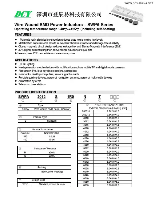
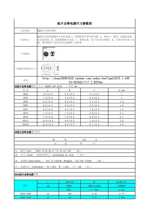
产品名称:CD贴片功率电感产品特点:产品图片产品图片图型及尺寸参考类 型A B C D ref CD32 3.0±0.3 3.0±0.3 2.1±0.31CD43 4.5±0.3 4.0±0.3 3.2±0.31CD52 5.8±0.3 5.2±0.3 2.1±0.3 1.6CD53 5.8±0.3 5.2±0.3 3.2±0.3 1.6CD54 5.8±0.3 5.2±0.3 4.5±0.3 1.3CD737.8±0.37.0±0.3 3.5±0.3 2.1CD757.8±0.37.0±0.3 5.0±0.3 2.1CD10410.0±0.39.0±0.3 4.0±0.3 2.9CD10510.0±0.39.0±0.35.4±0.32.9LTESTING DC RATED DC uH FREQ.RESISTANCE CURRENT (KHz).(Ω) MAX. A MAX CD32-100K 101000.230.76CD32-120K121000.270.685CD32贴片功率电感参数CD 75 - 221 K (1) (2) (3) (4)编号CD贴片功率电感图型及尺寸( SHAPE AND SIZE) ( 单位 mm )CD贴片功率电感编号表示(1). 编号(Type) : CD32/43/52/53/54/73/75/104/105 ( CD )(2). 尺寸(Size) : 成品外型尺寸(According to size) ( 75 )(3). 电感值(Inductance) : "221"表示220uH(Example: "221"for 220uH) ( 221 )(4). 电感公差(Tolerance) :"M:±20%, "K":±10% , "J":±5% ( K )/index.htm?spm=2013.1.w5002-5830017747.2.EYY36cCD贴片功率电感锰锌大功率电感 1、表面贴装小型功率电感。
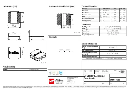
Dimensions: [mm]Scale - 7:1Product Marking:Marking330 (Inductance Code)7440404133074404041330BC74404041330T e m p e r a t u r eT pT L74404041330Cautions and Warnings:The following conditions apply to all goods within the product series of WE-LQS of Würth Elektronik eiSos GmbH & Co. KG:General:•This electronic component is designed and manufactured for use in general electronic equipment.•Würth Elektronik must be asked for written approval (following the PPAP procedure) before incorporating the components into any equipment in fields such as military, aerospace, aviation, nuclear control, submarine, transportation (automotive control, train control, ship control), transportation signal, disaster prevention, medical, public information network etc. where higher safety and reliability are especially required and/or if there is the possibility of direct damage or human injury.•Electronic components that will be used in safety-critical or high-reliability applications, should be pre-evaluated by the customer. •The component is designed and manufactured to be used within the datasheet specified values. If the usage and operation conditions specified in the datasheet are not met, the wire insulation may be damaged or dissolved.•Do not drop or impact the components, the component may be damaged.•Würth Elektronik products are qualified according to international standards, which are listed in each product reliability report. Würth Elektronik does not warrant any customer qualified product characteristics beyond Würth Elektroniks’ specifications, for its validity and sustainability over time.•The responsibility for the applicability of the customer specific products and use in a particular customer design is always within the authority of the customer. All technical specifications for standard products also apply to customer specific products.Product specific:Soldering:•The solder profile must comply with the technical product specifications. All other profiles will void the warranty.•All other soldering methods are at the customers’ own risk.•Strong forces which may affect the coplanarity of the components’ electrical connection with the PCB (i.e. pins), can damage the part, resulting in avoid of the warranty.Cleaning and Washing:•Washing agents used during the production to clean the customer application might damage or change the characteristics of the wire insulation, marking or plating. Washing agents may have a negative effect on the long-term functionality of the product.•Using a brush during the cleaning process may break the wire due to its small diameter. Therefore, we do not recommend using a brush during the PCB cleaning process.Potting:•If the product is potted in the customer application, the potting material may shrink or expand during and after hardening. Shrinking could lead to an incomplete seal, allowing contaminants into the core. Expansion could damage the components. We recommend a manual inspection after potting to avoid these effects.Storage Conditions:• A storage of Würth Elektronik products for longer than 12 months is not recommended. Within other effects, the terminals may suffer degradation, resulting in bad solderability. Therefore, all products shall be used within the period of 12 months based on the day of shipment.•Do not expose the components to direct sunlight.•The storage conditions in the original packaging are defined according to DIN EN 61760-2.•The storage conditions stated in the original packaging apply to the storage time and not to the transportation time of the components. Packaging:•The packaging specifications apply only to purchase orders comprising whole packaging units. If the ordered quantity exceeds or is lower than the specified packaging unit, packaging in accordance with the packaging specifications cannot be ensured. Handling:•Violation of the technical product specifications such as exceeding the nominal rated current will void the warranty.•Applying currents with audio-frequency signals may result in audible noise due to the magnetostrictive material properties.•The temperature rise of the component must be taken into consideration. The operating temperature is comprised of ambient temperature and temperature rise of the component.The operating temperature of the component shall not exceed the maximum temperature specified.These cautions and warnings comply with the state of the scientific and technical knowledge and are believed to be accurate and reliable.However, no responsibility is assumed for inaccuracies or incompleteness.Würth Elektronik eiSos GmbH & Co. KGEMC & Inductive SolutionsMax-Eyth-Str. 174638 WaldenburgGermanyCHECKED REVISION DATE (YYYY-MM-DD)GENERAL TOLERANCE PROJECTIONMETHODChriB001.0042023-02-28DIN ISO 2768-1mDESCRIPTIONWE-LQS SMT Semi-ShieldedPower Inductor ORDER CODE74404041330SIZE/TYPE BUSINESS UNIT STATUS PAGEImportant NotesThe following conditions apply to all goods within the product range of Würth Elektronik eiSos GmbH & Co. KG:1. General Customer ResponsibilitySome goods within the product range of Würth Elektronik eiSos GmbH & Co. KG contain statements regarding general suitability for certain application areas. These statements about suitability are based on our knowledge and experience of typical requirements concerning the areas, serve as general guidance and cannot be estimated as binding statements about the suitability for a customer application. The responsibility for the applicability and use in a particular customer design is always solely within the authority of the customer. Due to this fact it is up to the customer to evaluate, where appropriate to investigate and decide whether the device with the specific product characteristics described in the product specification is valid and suitable for the respective customer application or not.2. Customer Responsibility related to Specific, in particular Safety-Relevant ApplicationsIt has to be clearly pointed out that the possibility of a malfunction of electronic components or failure before the end of the usual lifetime cannot be completely eliminated in the current state of the art, even if the products are operated within the range of the specifications.In certain customer applications requiring a very high level of safety and especially in customer applications in which the malfunction or failure of an electronic component could endanger human life or health it must be ensured by most advanced technological aid of suitable design of the customer application that no injury or damage is caused to third parties in the event of malfunction or failure of an electronic component. Therefore, customer is cautioned to verify that data sheets are current before placing orders. The current data sheets can be downloaded at .3. Best Care and AttentionAny product-specific notes, cautions and warnings must be strictly observed. Any disregard will result in the loss of warranty.4. Customer Support for Product SpecificationsSome products within the product range may contain substances which are subject to restrictions in certain jurisdictions in order to serve specific technical requirements. Necessary information is available on request. In this case the field sales engineer or the internal sales person in charge should be contacted who will be happy to support in this matter.5. Product R&DDue to constant product improvement product specifications may change from time to time. As a standard reporting procedure of the Product Change Notification (PCN) according to the JEDEC-Standard inform about minor and major changes. In case of further queries regarding the PCN, the field sales engineer or the internal sales person in charge should be contacted. The basic responsibility of the customer as per Section 1 and 2 remains unaffected.6. Product Life CycleDue to technical progress and economical evaluation we also reserve the right to discontinue production and delivery of products. As a standard reporting procedure of the Product Termination Notification (PTN) according to the JEDEC-Standard we will inform at an early stage about inevitable product discontinuance. According to this we cannot guarantee that all products within our product range will always be available. Therefore it needs to be verified with the field sales engineer or the internal sales person in charge about the current product availability expectancy before or when the product for application design-in disposal is considered. The approach named above does not apply in the case of individual agreements deviating from the foregoing for customer-specific products.7. Property RightsAll the rights for contractual products produced by Würth Elektronik eiSos GmbH & Co. KG on the basis of ideas, development contracts as well as models or templates that are subject to copyright, patent or commercial protection supplied to the customer will remain with Würth Elektronik eiSos GmbH & Co. KG. Würth Elektronik eiSos GmbH & Co. KG does not warrant or represent that any license, either expressed or implied, is granted under any patent right, copyright, mask work right, or other intellectual property right relating to any combination, application, or process in which Würth Elektronik eiSos GmbH & Co. KG components or services are used.8. General Terms and ConditionsUnless otherwise agreed in individual contracts, all orders are subject to the current version of the “General Terms and Conditions of Würth Elektronik eiSos Group”, last version available at .Würth Elektronik eiSos GmbH & Co. KGEMC & Inductive SolutionsMax-Eyth-Str. 174638 WaldenburgGermanyCHECKED REVISION DATE (YYYY-MM-DD)GENERAL TOLERANCE PROJECTIONMETHODChriB001.0042023-02-28DIN ISO 2768-1mDESCRIPTIONWE-LQS SMT Semi-ShieldedPower Inductor ORDER CODE74404041330SIZE/TYPE BUSINESS UNIT STATUS PAGE。
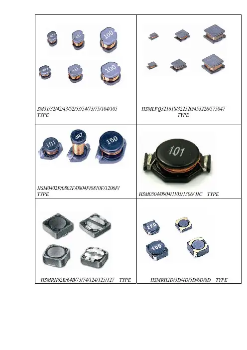
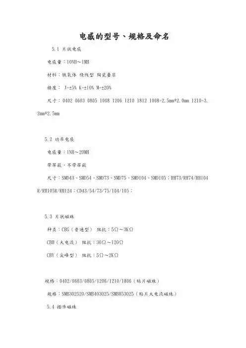
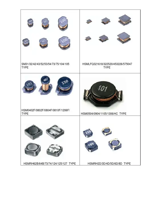
电感的型号、规格及命名5.1 片状电感电感量:10NH~1MH材料:铁氧体绕线型陶瓷叠层精度:J=±5% K=±10% M=±20%尺寸: 0402 0603 0805 1008 1206 1210 1812 1008=2.5mm*2.0mm 1210=3. 2mm*2.5mm5.2 功率电感电感量:1NH~20MH带屏蔽、不带屏蔽尺寸:SMD43、SMD54、SMD73、SMD75、SMD104、SMD105;RH73/RH74/RH104 R/RH105R/RH124;CD43/54/73/75/104/105;5.3 片状磁珠种类:CBG(普通型)阻抗:5Ω~3KΩCBH(大电流)阻抗:30Ω~120ΩCBY(尖峰型)阻抗:5Ω~2KΩ规格:0402/0603/0805/1206/1210/1806(贴片磁珠)规格:SMB302520/SMB403025/SMB853025(贴片大电流磁珠)5.4 插件磁珠规格:RH3.55.5 色环电感电感量:0.1uH~22MH尺寸:0204、0307、0410、0512豆形电感:0.1uH~22MH尺寸:0405、0606、0607、0909、0910精度:J=±5% K=±10% M=±20%精度:J=±5% K=±10% M=±20%插件的色环电感读法:同色环电阻的标示5.6 立式电感电感量:0.1uH~3MH规格:PK0455/PK0608/PK0810/PK0912 5.7轴向滤波电感规格:LGC0410/LGC0513/LGC0616/LGC1019电感量:0.1uH-10mH。
额定电流:65mA~10A。
Q值高,价位一般较低,自谐振频率高。
5.8 磁环电感规格:TC3026/TC3726/TC4426/TC5026尺寸(单位mm):3.25~15.885.9 空气芯电感空气芯电感为了取得较大的电感值,往往要用较多的漆包线绕成,而为了减少电感本身的线路电阻对直流电流的影响,要采用线径较粗的漆包线。
SunlordEXPERT IN PASSIVE PARTSPower Inductor SPH Series香港伟创国际有限公司2012.8Sunlord confidential0755-89667799 www.foxtron.com.cnSunlordEXPERT IN PASSIVE PARTSContentsInner Structure Process Flow Chart Electrical Characteristics Failure Mode Land Pattern Compatibility Sunlord Product RoadmapSunlord confidential0755-89667799 www.foxtron.com.cnSunlordEXPERT IN PASSIVE PARTSInner StructureSunlord SPH252012H Copper wire Copper wire TDK VLS252012TMagnetic ResinFerrite CoreMagnetic ResinFerrite CoreCYNTEC PSE25201BTOKO DFE252012CCopper wireCopper wireMagnetic ResinFerrite Core Iron powder ElectrodeThe structure of Cyntec’s/TDK’s and Sunlord’s power inductor are similar. The structure of Toko’s DFE252012C is different from others.Sunlord confidential0755-89667799 www.foxtron.com.cnSunlordEXPERT IN PASSIVE PARTSProcess Flow ChartSunlord SPH Process:PlatingWire woundSolderingResin CoatingCYNTEC PSE25201B Process:Almost the samePlatingWire WoundsolderingResin CoatingTDK VLS252012T Process:PlatingWire WoundWeldingResin CoatingHot pressure welding makes ferrite and electrode connectedSunlord confidential0755-89667799 www.foxtron.com.cnSunlordEXPERT IN PASSIVE PARTSProcess Flow ChartTOKO DFE Process:Wire woundmoldingThe film of copper wire processingConductive glueCuringThe process of Toko’s DFE252012C is absolutely different from others.Sunlord confidential0755-89667799 www.foxtron.com.cnSunlordEXPERT IN PASSIVE PARTSComparisons of manufacturing processesItem Uncontrolla ble risk Sunlord SPH252012H All parameters are quantitative, and under control. TDK VLS252012T Using welding Method, exists visual defect (fissure) and open circuit risk. Cyntec PSE 25201B All parameters are quantitative, and under control. Toko DFE252012 Pressure (Molding process) is not easy to control, exists the risk to damage copper wire and result in short. Low(80%)First pass yieldHigh(99.7%) (Japanese accuracy devices) High(100%) It’s easy to produce smallsize products, such as the 2016 &2012.Low(80%) (core visual defect in molding and welding) High(100%) GoodGood(95%) (Taiwan devices)Automatic Processing ExtensibilityHigh(100%) It’s easy to produce small-size products, such as the 2016 &2012.Low(50%) Can NotSunlord confidential0755-89667799 www.foxtron.com.cnSunlordEXPERT IN PASSIVE PARTSElectric CharacteristicFor Example (spec.):Indctance (μH) DCR(Ω) Max. 0.090 0.155 Typ. 0.080 0.129 Isat(A) Max. 1.75 1.8 Typ. 1.85 2.0 Irms(A) Max. 1.95 Typ. 2.15 1.30CompanyP/NCyntec TDKPSE25201B-2R2MS-39 VLS252012T-2R2M1R3 DFE252012 Series 1239AS-H-2R2 SPH252012H2R2MT2.2±20% 2.2±20%Toko2.2±30%0.1080.0902.202.702.002.30Sunlord2.2±20%0.0960.0801.801.951.802.00Sunlord confidential0755-89667799 www.foxtron.com.cnSunlordEXPERT IN PASSIVE PARTSElectric CharacteristicFor Example (test value.):Company P/N Indctance (μH) 2.2±20% 2.2±30% 2.2±20% DCR(Ω) Max. / / / Typ. 0.084 0.090 0.085 Isat(A) Max. 1.85 1.80 1.80 Typ. 2.15 2.70 2.05 Irms(A) Max. 1.84 1.71 1.82 Typ. 2.09 1.96 2.05Cyntec Toko SunlordPSE25201B-2R2MS-39 DFE252012 Series 1239AS-H-2R2 SPH252012H2R2MTTemperature Rise Curve60 Temperature Rise (℃)Satraution Curve 10% TOKO DFE252012C-2R2 Cyntec PSE252001B-2R2MS Sunlord SPH252012H-2R2TOKO DFE252012C-2R2 Cyntec PSE25201B-2R2Drop ratio40Sunlord SPH252012H-2R20%-10%20-20%0 0.0 0.5 1.5 D.C. Current (A) 1.0 2.0 2.5-30% 0.0 0.5 1.0 1.5 D.C. Current (A) 2.0 2.5Sunlord confidential0755-89667799 www.foxtron.com.cnSunlordEXPERT IN PASSIVE PARTSFor Example (test value):L-F Curve 6 5 Inductance (μH) 4 3 2 1 0 1 10 Frequency (MHz )Electric CharacteristicQ-F CurveTOKO DFE252012C-2R2 Cyntec PSE25201B-2R2 Sunlord SPH252012H-2R240TOKO DFE252012C-2R2 Cyntec PSE25201B-2R2 Sunlord SPH252012H-2R23020Q100 1000100 1 10 Frequency (MHz) 100 1000Z-F Curve 5 TOKO DFE252012C-2R2 Cyntec PSE25201B-2R2 Sunlord SPH252012H-2R24Z(KΩ)3210 1 10 Frequency (MHz) 100 1000Sunlord confidential0755-89667799 www.foxtron.com.cnSunlordEXPERT IN PASSIVE PARTSFor Example (test value):Electric CharacteristicAC R -F C u rv e 20 T O K O D F E 2 5 2 0 1 2 C -2 R 2 C y n te c P S E 2 5 2 0 1 B -2 R 2 S u n lo rd S P H 2 5 2 0 1 2 H -2 R 215 ACR(Ω)1050 1 2 3 4 5 6 7 8 9 10 F re q u e n c y (M H z )At frequency above 2.5MHz, DFE's Rac begins to increase sharply. This is not compliant with the requirements of high-frequency trend Sunlord confidential0755-89667799 www.foxtron.com.cnEXPERT IN PASSIVE PARTSTemperature coefficient :Electric CharacteristicL-T Curve1.82.02.2-50-30-101030507090Temperature (℃)I n d u c t a n c e(μH )TOKO DFE252012C-2R2Cyntec PSE25201B-2R2Sunlord SPH252012H-2R2I=0AEXPERT IN PASSIVE PARTSTemperature coefficient :Electric CharacteristicI=0.5AL-T Curve1.82.02.2-50-30-101030507090Temperature (℃)I n d u c t a n c e (μH )TOKO DFE252012C-2R2Cyntec PSE25201B-2R2Sunlord SPH252012H-2R2EXPERT IN PASSIVE PARTSTemperature coefficient :Electric CharacteristicI=1.0AL-T Curve1.82.02.2-50-30-101030507090Temperature (℃)I n d u c t a n c e (μH )TOKO DFE252012C-2R2Cyntec PSE25201B-2R2Sunlord SPH252012H-2R2EXPERT IN PASSIVE PARTSTemperature coefficient :Electric CharacteristicI=1.5AL-T Curve1.61.82.02.2-50-30-101030507090Temperature (℃)I n d u c t a n c e (μH )TOKO DFE252012C-2R2Cyntec PSE25201B-2R2Sunlord SPH252012H-2R2EXPERT IN PASSIVE PARTSTemperature coefficient :Electric CharacteristicI=2.0AL-T Curve1.21.41.61.82.0-50-30-101030507090Temperature (℃)I n d u c t a n c e (μH )TOKO DFE252012C-2R2Cyntec PSE25201B-2R2Sunlord SPH252012H-2R2EXPERT IN PASSIVE PARTSTemperature coefficient :Electric CharacteristicI=2.5AL-T Curve0.30.50.70.91.11.31.51.71.9-50-30-101030507090Temperature (℃)I n d u c t a n c e (μH )TOKO DFE252012C-2R2Cyntec PSE25201B-2R2Sunlord SPH252012H-2R2EXPERT IN PASSIVE PARTSWithstanding voltage test Test condition: 1000V/0.2sec Measuring device:TH2817B200060Test times -4.4%-98.1%L Rate of change +2.5%-41.8%DCR OKNG (Short)Result 0.0830.0522DCR(m OHM)2.170.0812.27Sunlord SPH252012H0.0420.08972.23Toko DFE252012C L(uH)DCR(m OHM)L(uH)After Test Before Test Item Failure(short) LocationFailure ModeEXPERT IN PASSIVE PARTSacb bacb bBACTest valueSpec. 2.10.81.01.2Max.2.0±0.22.5±0.2///1.222.212.68c b a T L WSunlord SPH252012HCYNTEC PSE25201BTDK VLS252012T (spec.)TOKO DFE252012CShape and DimensionsTest valueSpec. 2.10.850.801.2Max.2.0±0.22.5±0.2///1.152.202.52c b a T L WTest valueSpec.///1.2Max.2.0±0.22.5±0.2///1.192.202.68c b a T L W ¾Sunlord’s power inductor has the smallest shape in testing value.EXPERT IN PASSIVE PARTS Land Pattern Compatibility¾TDK’s and Sunlord’s power inductor are the same in land pattern.¾Cyntec’s power inductor has a little different from the two maker’s products in land pattern.¾The land pattern of Toko’s power inductor is incompatible with mainstream makers’.In case of emergency, it’s very hard to be replaced.EXPERT IN PASSIVE PARTSWire Wound Power Inductors RoadmapFor Wire Wound Power Inductors, focus on the height of 1.0mm and overSPH8030SSPH4018SSPH4012SSPH3015SSPH252012SSPH252010SSPH202012SSPH201610SSPH1608SSunlordEXPERT IN PASSIVE PARTSSunlord confidential0755-89667799 www.foxtron.com.cn。
AMENDMENT RECORD TYPESDRH104 SYMBOL DATE PAGE CONTENTS DWN. BY CHK. BY APP. BY00 2010/09/09 NEW ISSUE L.WANG Y.L.LI Y.B.ZENGSPEC. No. 2/6U666-6063SPECIFICATION 1. DIMENSION(UNIT:mm)※ THE DIMENSIONS WITHOUT TOLERANCE ARE APPROX.2. RECOMMENDED DIMENSIONS (mm)3. CONNECTION (TOP VIEW)4.STAMPING (e.g.)TYPESDRH1044.7µH~39µHUNFIXED POSITION2.047µH~470µH5.ELECTRICAL CHARACTERISTIC* TESTING INSTRUMENTINDUCTANCE : HP 4284A OR EQUIV ALENT. D.C.R : TH2512B OR EQUIV ALENT. (Ta= 20℃)SATURA TION CURRENT: WK 3260B+3265B OR EQUIV ALENT.* TESTING CONDITIONS OF INDUCTANCE :(4.7-6.8µH )at 100 kHz /1V (10-470µH )at 1 kHz /1V . * SATURA TION CURRENT: INDICATES THE CURRENT WHEN THE INDUCTANCE DECREASES TO 75% OF INITIAL V ALUE. (Ta=20℃)No.UTOP P /N.CUS TOMERP /N.STAMPINDUCTANCE (µH)WI THI ND.C.R.(m Ω)Max.S ATURATION CURRENT(A)01 SDRH104-4R7NC 4R7 4.7±30% 35 3.2 02 SDRH104-6R8NC 6R8 6.8±30% 44 2.8 03 SDRH104-100MC 100 10±20% 50 2.4 04 SDRH104-120MC 120 12±20% 54 2.25 05 SDRH104-150MC 150 15±20% 61 2.0 06 SDRH104-180MC 180 18±20% 84 1.8 07 SDRH104-220MC 220 22±20% 94 1.65 08 SDRH104-270MC 270 27±20% 110 1.45 09 SDRH104-330MC 330 33±20% 150 1.35 10 SDRH104-390MC 390 39±20% 170 1.2 11 SDRH104-470MC 470 47±20% 210 1.1 12 SDRH104-560MC 560 56±20% 230 1.0 13 SDRH104-680MC 680 68±20% 260 0.93 14 SDRH104-820MC 820 82±20% 360 0.84 15 SDRH104-101MC 101 100±20% 410 0.76 16 SDRH104-121MC 121 120±20% 450 0.70 17 SDRH104-151MC 151 150±20% 640 0.63 18 SDRH104-181MC 181 180±20% 840 0.57 19 SDRH104-221MC 221 220±20% 960 0.52 20 SDRH104-271MC 271 270±20% 1070 0.47 21 SDRH104-331MC 331 330±20% 1370 0.43 22 SDRH104-391MC 391 390±20% 1550 0.39 23SDRH104-471MC471470±20%17400.36TYPESDRH104REMARKSPEC. No. 4/6U666-60636. GENERAL CHARACTERISTICS* STANDARD TESTING CONDITIONS:UNLESS OTHERWISE SPECIFIED, THE STANDARD RANGE OF ATMOSPHERIC CONDITIONS FOR MEASUREMENTS AND TESTS ARE AS FOLLOWS: AMBIENT TEMPERATURE: 15℃~35℃.RELATIVE HUMIDITY : 25% ~85%. AIR PRESSURE : 86kPa ~106kPa.IF THERE IS ANY DOUBT ABOUT THE RESULTS, MEASUREMENT SHALL BE MADE WITHIN THE FOLLOWING LIMITS: AMBIENT TEMPERATURE: 20℃±1℃. RELATIVE HUMIDITY: 63% ~67%.AIR PRESSURE : 86kPa ~106kPa.No. ITEMS CONDITIONS SPECIFICATION1 OPERA TION TEMPERA TURESTORAGE TEMPERA TURE -25 ~+ 85℃(INCLUDING COIL TEMPERA TURE RISE) -30 ~+ 85℃2 TEMPERA TURE COEFFICIENT -30 ~+85℃0 ~2000 ppm/℃3 FIXING STRENGTH SAMPLE IS PUSHED IN THREE DIRECTIONS OFX, Y AND Z WITH FORCE OF 5. 0N FOR 10±5SECONDS. AFTER SOLDERING BETWEENCOPPER PLA TE AND ELECTRODES.NO ELECTRODE DETACHMENT.4 RESISTANCE TO SOLDERINGHEA T TEST REFER TO THE SPEC “STD-001NP”. NO MECHANICAL BREAKAGE.DEVIA TION RELATIVE TO INITIALV ALUE:L: WITHIN ±5.0%5 SOLDERABILITY TEST IMMERSE THE ELECTRODE IN FLUX FOR 5SECONDS. THEN DIP THE ELECTRODE INTO ASOLDERING BA TH OF 245±5℃ FOR 2±0.5SECONDS. OVER 95% OF THE SURFACE BEING IMMERSED SHALL BE COVERED WITH NEW SOLDER UNIFORMLY.6 VIBRA TION TEST AMPLITUDE: 1.5mm P-PFREQUENCY:10~55~10Hz (1 MINUTE PER CYCLE)DURATION: 1 HOUR IN EACH OF X, Y, Z AXIS. DEVIA TION RELATIVE TO INITIAL V ALUE:L: WITHIN ±5.0%7 HUMIDITY TEST TEMPERA TURE: 40℃±2℃HUMIDITY: 90%~95%RHDURATION: 96±4 HOURS. DEVIA TION RELATIVE TO INITIAL V ALUE:L: WITHIN ±5.0%8 THERMAL SHOCK TEST 20 CYCLES OF +85℃FOR 30 MINUTES, -40℃FOR 30 MINUTES. CHARACTERISTICS AREMEASURED AFTER THE AMBIENT AIREXPOSURE OF 1 HOUR9 HIGH TEMPERA TURESTORAGE TEST TEMPERA TURE: 85℃±2℃DURATION: 96±4 HOURS10 LOW TEMPERA TURESTORAGE TEST TEMPERA TURE: -30℃±3℃DURATION: 96±4 HOURS.DEVIA TION RELATIVE TO INITIALV ALUE:L: WITHIN ±5.0%REMARK SPEC. No.5/6U666-60637. PACKINGPACKAGE TO BE ACCORDING TO PACKAGE SPECIFICATIONS (TICK THE RELEV ANT “ ” ) □KB-CTR049;* ENCLOSING CONDITION OF COILS.8. REMARK1.RoHS COMPLIANCE REMARKS* LEAD WILL BE PRESENT IN THE FERRITE CORE OF THE FRIT MATRIX IN THE COMPONENT.THIS USE, IS EXEMPT FROM RoHS LEGISLATION PER THE ANNEX (ITEM 7), WHICHREFERS TO “LEAD IN ELECTRONIC CERAMIC PART”.REMARK SPEC. No.6/6U666-6063。